- Table of Contents
- Related Documents
-
| Title | Size | Download |
|---|---|---|
| 03-MPLS VPLS Configuration | 415.55 KB |
Table of Contents
1.1.2 Basic VPLS Network Architectures
1.1.3 VPLS Basic Transmission Components
1.2.1 VPLS Configuration Task List
1.2.2 Configuring Routing Protocols
1.2.3 Configuring Basic MPLS Functions
1.2.4 Configuring LDP Expansion Session Peer
1.2.6 Creating a VPLS Instance
1.2.7 Configuring VLAN for User Access and Binding a VLPS Instance
1.2.8 Configuring Static MAC Address
1.2.9 Enabling VLAN VPN on a Port
1.2.10 Configuring User-Defined Flow Template
1.2.12 Configuring MPLS Redirection
1.2.13 Configuring VPLS Load Sharing
1.2.14 Configuring VPLS Characteristics
1.3 Displaying and Debugging VPLS
1.4 VPLS Configuration Examples
1.4.1 VPLS Basic Configuration Example (1)
1.4.2 VPLS Basic Configuration Example (2)
1.4.3 Hierarchical VPLS Configuration Example (via MPLS)
1.4.4 Hierarchical VPLS Configuration Example (via QinQ)
1.4.5 VPLS Load Sharing Configuration Example
Chapter 1 VPLS Configuration
When configuring VPLS, go to these sections for information you are interested in:
l Displaying and Debugging VPLS
& Note:
The service processor card mentioned in this chapter refers to the LSB1VPNB0 card.
Terms used in this document are listed below:
Table 1-1 Terminology
|
Term |
Full name |
|
AC |
Attachment Circuit |
|
CE |
Customer Edge |
|
FEC |
Forwarding Equivalence Class |
|
FR |
Frame Relay |
|
NPE |
Network Facing PE |
|
PE |
Provider Edge |
|
PW |
Pseudowire |
|
PHP |
Penultimate Hop Popping |
|
UPE |
User Facing PE |
|
VLL |
Virtual Leased Line |
|
VPLS |
Virtual Private LAN Service |
|
VSI |
Virtual Switching Instance |
|
LSP |
Label Switched Path |
1.1 VPLS Overview
1.1.1 Introduction to VPLS
Today, IP networks have spread throughout the world. And the operators are focusing on using their existing IP networks to provide enterprises with low-cost private networks. Now, an easy-implemented technique called MPLS VPN (multiprotocol label switching VPN) emerges as the times require, which enables the operators to provide arbitrary-rate MPLS-based virtual private network (VPN) services over IP networks.
MPLS VPN services fall into two types: MPLS L3VPN and MPLS L2VPN. The latter includes VPLS (virtual private LAN service) and VLL (virtual leased line). VLL only applies to point-to-point networking, while VPLS can apply to multipoint-to-multipoint VPN networking. VPLS provides the operators using point-to-point L2VPN with a better solution. In addition, unlike L3VPN, VPLS does not participate in user's internal routing. Now, operators need only manage and operate a single network to provide multiple kinds of services such as best-effort, L3VPN, L2VPN, traffic-engineering, and distinguished services. This greatly reduces their costs on network construction, operation and maintenance.
With VPLS, users in different areas can be connected with each other through MAN/WAN just like they are in one LAN. S9500 series provide a VPLS solution. This solution uses MPLS-based virtual links as the links of Ethernet bridges and provides transparent transmission LAN services (TLS) over MPLS networks.
1.1.2 Basic VPLS Network Architectures
There are two kinds of VPLS network architectures: PW logically meshed VPLS network architecture and hierarchical architecture. Figure 1-1 depicts a VPLS network architecture with PW logical multipoint-to-multipoint connection.
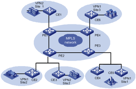
Figure 1-2 Network diagram for PW logically meshed VPLS network
As shown in Figure 1-1, VPLS can provide point-to-multipoint connection service like a L3VPN. It can learn MAC addresses and exchange packets between multiple sites. In addition, it keeps the forwarding tables of the individual VPNs independent with each other and allows MAC address overlap between VPNs.
Figure 1-2 depicts a hierarchical VPLS network architecture.
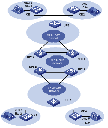
Figure 1-3 Hierarchical VPLS network architecture
As shown in Figure 1-2, the network topology of the VPLS network is hierarchical, and the access range of the network is expansible. The core devices (NPEs) in the core network require high performance because VPN traffic concentrates there, while the edge devices (UPEs) require lower performance because they are mainly used for VPN service access. In addition, you can back up the links between NPEs and UPEs to make the network more robust. The access networks between UPEs and NPEs can be either a MPLS edge network connected by LSP, or a simple Ethernet network for VLAN-VPN user access.
The S9500 series routing switches support hierarchical VPLS (H-VPLS) networking. In a hierarchical VPLS network, the UPE and NPE devices can be interconnected through an MPLS edge network (by LSP connections) or through a simple Ethernet switched network (VLAN-VPN access) to provide link redundancy.
In the case of access through an MPLS edge network, only one of the VPLS primary and backup PWs is in the forwarding state at a time. The VPLS network supports the "split horizon" principle for avoiding loops.
In the case of access through VLAN-VPN, MSTP needs to run between the UPE and NPE links. The two NPE devices connected with the UPE device only transparently transmit BPDUs between each other. To avoid propagating BPDUs to the VPLS network, different VPLS instances are used on the NPE devices for transparent transmission of user data packets and BPDUs.
1.1.3 VPLS Basic Transmission Components
As shown in the following figure, the whole VPLS network is just like a huge switch. For each VPN, it sets up PWs between the sites of the VPN on MPLS tunnels and transparently transmits user's Layer 2 packets from one site to another through these PWs. In this network, PEs forward packets, learn source MAC addresses, create MAC forwarding entries, and map the MAC addresses to corresponding ACs and PWs. While, the P devices (provider routers, that is, core switches in the backbone network), only implement MPLS forwarding according to MPLS labels without considering Layer 2 user data encapsulated in MPLS packets.
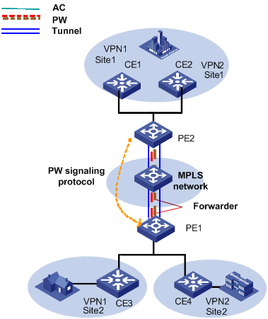
Figure 1-4 L2VPN universal transmission components
The transmission components and their functions in a VPLS network are as follows:
l Attachment circuit
An attachment circuit (AC) is a virtual connection link between CE and PE. User’s Layer 2 and layer 3 data are transmitted to the peer site through AC without any modification.
l Pseudowire
A pseudowire (PW) is a bidirectional virtual connection between two VSIs in a VPN. One PW contains a pair of unidirectional MPLS VCs (virtual circuits). It is established by PW signaling protocol and carried on LSP. For a VPLS system, a PW is just like a directly connected path between local and peer ACs, through which user’s Layer 2 data are transmitted transparently.
l Forwarder
A forwarder is in fact a VPLS forwarding table, it chooses PWs to forward the frames that PEs received from ACs.
l Tunnel
A tunnel is a directly connected path between local PE and peer PEs, on which data is transmitted transparently from one PE to another. A tunnel can carry multiple PWs. In general, a tunnel is an MPLS tunnel.
l Encapsulation
Standard PW encapsulation formats and technique are adopted when packets are transmitted over PWs. VPLS packets carried on PWs have two encapsulation modes: VLAN and Ethernet.
l PW signaling
PW signaling (pseudowire signaling) protocol on which VPLS bases is used to establish and maintain PW. It can also be used to automatically discover peer PEs of VSIs. Currently, PW signaling protocol includes label distribution protocol (LDP) and border gateway protocol (BGP).
l Service quality
Service quality maps priority information in the headers of user’s Layer 2 packets and QoS information carried by VSI instances to QoS priority of the public network before the forwarding of the packets. This feature generally requires the MPLS network to support traffic-engineering.
As shown in Figure 1-3, CE3 transmits uplink Layer 2 packets to PE1 through AC. When PE1 receives the packets, the forwarder chooses PW to forward them. According to PW forwarding entries, the system generates two layers of MPLS labels (private network labels are used to mark the PWs, and public network labels are used to pass through tunnels to PE2) and the Ethernet headers of the public network. After the packets reach PE2 through public network tunnel, the system pops out private network labels (public network labels have already been popped out on P device through PHP). PE2 forwarder chooses an AC to forward Layer 2 packets from CE3 to CE1.
1.2 VPLS Basic Configuration
1.2.1 VPLS Configuration Task List
|
To do... |
Use the command... |
Remarks |
|
Configure routing protocol for public network |
Refer to the related sections in Operation Manual – Routing Protocol |
Required |
|
Configure basic MPLS functions |
Refer to chapter 2 Configuring MPLS Basic Functions in Operation Manual – MPLS |
Required |
|
Configure LDP expansion session peer |
mpls ldp remoter-peer index |
Required |
|
Enabling L2VPN |
mpls l2vpn |
Required |
|
Configure a VPLS instance |
vsi vsi-name [ static ] |
Required. static is required for configuring a VSI. |
|
Configure an IP address of a peer PE |
peer peer-ip [ vc-id vc-id ] [ upe | dual-npe ] [ encapsulation { ethernet | vlan } ] |
Required |
|
Configure static MAC addresses |
mac-address { static H-H-H } vsi vsi-name { peer { peer-ip | dual-npe } | vlan-interface vlan-id } |
Optional |
|
Configure VLAN for user access and binding VSI |
l2 binding vsi vsi-name [ access-mode { vlan | ethernet } ] |
Required |
|
Configure VPLS characteristics |
bandwidth bw-limit |
Optional |
|
Enable VLAN VPN (Q-in-Q) on port |
vlan-vpn enable |
Optional |
|
Configure user-defined flow template |
flow-template user-defined slot slotnum template-info |
Required |
|
Configure ACL rules |
rule rule-id permit mpls l2label-range ingress any egress any |
Required |
|
Configure packet redirection |
traffic-redirect inbound link-group { acl-number | acl-name } [ rule rule [ system-index index ] ] | slot slotid vlanid [ join-vlan ] } |
Required |
|
Enable VPLS load sharing |
vpls-load-share enable |
Optional Enabled by default |
![]() Caution:
Caution:
L2VPN VPLS does not support NDP transparent transmission.
1.2.2 Configuring Routing Protocols
You must perform some basic routing configuration on your switch such that it can exchange routing information with other P and PE devices. Currently, you can choose the following routing protocols: static routing, routing information protocol (RIP), open shortest path first (OSPF), exterior border gateway protocol (EBGP), and so on. For specific configuration, refer to the IP Routing Volume.
1.2.3 Configuring Basic MPLS Functions
Configure basic MPLS functions to create LSP tunnels over public network. For specific configuration, refer to MPLS Configuration.
1.2.4 Configuring LDP Expansion Session Peer
Configure LDP remote peer to set up LDP remote session.
I. Entering the remote-peer mode
Perform the following configuration in system view to enter the remote-peer mode:
|
To do... |
Use the command... |
|
Enter the remote-peer mode |
mpls ldp remote-peer index |
|
Remove the remote peer |
undo mpls ldp remote-peer index |
By default, no remote peer exists.
II. Configuring an address for the remote peer
You can specify any LDP-enabled interface address of a remote peer device or the loopback address of a label switch router (LSR) that has advertised its routing information as the address of the remote peer.
Perform the following configuration in remote-peer view to configure an address for the remote peer:
|
To do... |
Use the command... |
|
Configure an address for the remote peer |
remote-ip remoteip |
1.2.5 Enabling L2VPN
Enable L2VPN globally before you configure VPLS and VLL; otherwise you cannot configure VPLS and VLL.
Perform the following configuration in system view to enable L2VPN:
|
To do... |
Use the command... |
|
Enable MPLS L2VPN |
mpls l2vpn |
|
Disable MPLS L2VPN |
undo mpls l2vpn |
By default, MPLS L2VPN is disabled.
1.2.6 Creating a VPLS Instance
I. Specifying a VPLS instance name
Use the vsi command to create a VPLS instance or enter VSI view. When creating a VPLS instance, you must specify a locally unique VPLS instance name, and must choose automatic discovery or manual configuration as peer discovery mechanism. Currently, only manual configuration, namely, static mode, is supported.
Perform the following operation to configure/remove a VPLS instance name:
|
To do... |
Use the command... |
|
Specify a VPLS instance name |
vsi vsi-name [ static ] [ encapsulation { ethernet | vlan } ] |
|
Remove a VPLS instance or quit the VSI view |
undo vsi vsi-name |
II. Entering VSI-LDP view and configure VSI-ID
Use the pwsignal command to specify a PW signaling protocol used by the VSI and enter the VSI-LDP view.
Specifying LDP as the PW signaling protocol for the VSI takes you to the VSI-LDP view
Perform the following configuration in VSI view to specify VSI to use PW signalling:
|
To do... |
Use the command... |
|
Specify the PW signaling protocol to be used by the VSI |
pwsignal [ ldp ] |
Currently, PW signaling supports LDP only.
Use the vsi-id command to specify an ID for the current VSI. The ID must be locally unique.
Perform the following configuration in VSI-LDP view to configure a VPLS instance:
|
To do... |
Use the command... |
|
Specify a ID for the current VSI |
vsi-id vsi-id |
III. Configuring an IP address of a peer PE
Use the peer command to create a VPLS peer PE contained in an instance. When you create a VPLS peer PE, you must specify an IP address and peer type for the peer PE. By default, the peer type is NPE. When you specify UPE as the peer type, it indicates the peer is a user convergence node UPE in hierarchical VPLS architecture. You can also specify an ID for a VC to the peer, and the ID must be consistent with that of the remote. Multipoint-to-multipoint connections are needed among specified multiple remote peer NPEs, but not needed between UPEs and NPEs.
Perform the following configuration in VSI-LDP view to configure an IP address for a peer PE:
|
To do... |
Use the command... |
|
Create a VPLS peer PE contained in the instance |
peer peer-ip [ vc-id vc-id ] [ upe | dual-npe ] [ encapsulation { ethernet | vlan } ] |
|
Remove the specified VPLS peer PE |
undo peer peer-ip |
By default, VC-ID is as big as VSI-ID.
IV. Specifying the VC encapsulation type of the VSI
Perform the following configuration in VSI view to specify the VC encapsulation type of the VSI:
|
To do... |
Use the command... |
|
Specify the VC encapsulation type of the VSI |
encapsulation { vlan | ethernet } |
By default, the VC encapsulation type in the VSI takes this value.
1.2.7 Configuring VLAN for User Access and Binding a VLPS Instance
The port configuration on a VLAN interface differs depending on user access modes. If user gets access by Ethernet, you must enable VLAN-VPN on the access port of the VLAN. If user makes H-VPLS access by VLAN, or user's convergence multi-tenant unit (MTU) makes H-VPLS access by VLAN-VPN, you need not enable VLAN-VPN on the access port; instead, you must configure the port as Trunk, in this case, the VLAN Tag (VLAN ID currently configured for the user) carried in uplink packets must be consistent with that of the VLAN bound with the Trunk. If convergence UPE makes H-VPLS access by LSP, you can bind a VPLS instance to a VLAN containing no port. Additionally, you cannot bind one instance to multiple VLANs.
Perform the following configuration in VLAN interface view to configure VLAN for user access and bind a VPLS instance:
|
To do... |
Use the command... |
|
Bind a VPLS instance to a VLAN interface |
l2 binding vsi vsi-name [ access-mode { vlan | ethernet } ] |
|
Remove the binding |
undo l2 binding vsi vsi-name |
![]() Caution:
Caution:
l If any of GVRP, STP and 802.1x protocols is enabled on a port, you cannot enable VLAN VPN on the port;
l If IGMP Snooping is enabled in the VLAN to which the port belongs or if IGMP is enabled on the VLAN interface to which the port belongs, it is not allowed to enable VLAN VPN on the port, and vice versa;
l If a port with enabled VLAN VPN is to join in a VLAN, IGMP Snooping cannot be enabled on the VLAN and IGMP cannot be enabled on its VLAN interfaces;
l The interface of a VLAN with a VPLS instance bound to it cannot be assigned an IP address. Similarly, if the interface of a VLAN is assigned an IP address, you cannot bind VPLS instances to it.
l A VPLS instance can be bound to multiple VLANs. You can bind a VPLS instance to up to eight VLANs.
l It is not allowed to bind VSI instances to VLAN-interface1.
1.2.8 Configuring Static MAC Address
Use the mac-address command to configure a static MAC address for the VPLS instance. The address you configured can be either a MAC address on a local CE or a MAC address on a remote CE.
Perform the following configuration in system view to configure static MAC address:
|
To do... |
Use the command... |
|
Configure a static MAC address for VPLS instance |
mac-address { static H-H-H } vsi vsi-name { peer { peer-ip | dual-npe } | vlan-interface vlan-id } |
|
Remove the MAC address |
undo mac-address { static H-H-H } vsi vsi-name |
|
undo mac-address vsi [ vsi-name [ peer { peer-ip | dual-npe } | vlan-interface vlan-id ] ] [ static | dynamic ] |
![]() Caution:
Caution:
l You are not recommended to configure a remote static MAC address when there are more than one peer relationship to the same remote system for a VSI instance.
l In case you have configured a remote static MAC address and the peer IP address you specified is the same as that of one of the NPEs in the H-VPLS of the instance, the remote peer defaults to use dual-npe and the word dual-npe will be displayed when you view the MAC forwarding entries. You may not delete the MAC configuration thoroughly by specifying the peer IP address. To delete the MAC configuration completely, you need to specify the MAC address.
1.2.9 Enabling VLAN VPN on a Port
![]() Caution:
Caution:
User access mode of VSI determines whether you should enable VLAN-VPN on a port or not. If the access mode is Ethernet, you must enable VLAN-VPN on the access port such that your private VLAN Tag can be properly transferred. If the access mode is VLAN, you must set the access port to Trunk.
Perform the following configuration in Ethernet port view to enable VLAN VPN on a port:
|
To do... |
Use the command... |
|
Enable VLAN VPN on a port |
vlan-vpn enable |
|
Disable VLAN VPN on the port |
undo vlan-vpn |
![]() Caution:
Caution:
l If GARP VLAN registration protocol (GVRP), spanning tree protocol (STP) or 802.1x protocol is enabled on a port, VLAN VPN on this port is not allowed to enable.
l If IGMP Snooping is enabled in the VLAN to which the port belongs or if IGMP is enabled on the VLAN interface to which the port belongs, it is not allowed to enable VLAN VPN on the port, and vice versa.
l If a port with enabled VLAN VPN is to join in a VLAN, IGMP Snooping cannot be enabled on the VLAN and IGMP cannot be enabled on its VLAN interfaces.
By default, VLAN VPN is disabled on ports.
1.2.10 Configuring User-Defined Flow Template
Perform the following configuration in system view to configure user-defined flow template:
|
To do... |
Use the command... |
|
Define flow template |
flow-template user-defined slot slotnum template-info |
|
Define user flow template in port view |
flow-template user-defined |
|
Remove flow template |
undo flow-template user-defined |
When you define the flow template, the total size of all the elements in the template must be less than 16 bytes.
& Note:
In a flow template definition, the slotnum argument refers to the slot number of the interface card that interfaces with the MPLS network.
1.2.11 Configuring ACL Rules
Use the following commands to define a Layer 2 ACL.
Perform the following configuration in corresponding views to configure ACL rules:
|
To do... |
Use the command... |
|
Enter a Layer 2 ACL view from system view |
acl { number acl-number | name acl-name advanced } [ match-order { config | auto } ] |
|
Define a sub-rule in Layer 2 ACL view |
rule [ rule-id ] { permit | deny } [ packet-level { bridge | route } | cos cos-value | c-tag-cos c-cos-value | exp exp-value | protocol-type | mac-type { any-broadcast-packet | arp-broadcast-packet | non-arp-broadcast-packet | { { unicast-packet | multicast-packet } [ known | unknown ] } } | ingress { { source-vlan-id [ to source-vlan-id-end ] | source-mac-addr source-mac-wildcard | c-tag-vlan c-tag-vlan } * | any } | egress { dest-mac-addr dest-mac-wildcard | any } | s-tag-vlan s-tag-vlanid | time-range name ] * |
|
Remove a sub-rule in Layer 2 ACL view |
undo rule rule-id |
|
Remove Layer 2 ACL or all ACLs in system view |
undo acl { number acl-number | name acl-name | all } |
& Note:
l In an ACL rule that defines a VPLS label range, the rang-id argument refers to the VPLS label range ID. On an S9500 series switch, the entire VPLS supported label range is divided into 8 label ranges with equal space. These 8 ranges correspond to range IDs 0 through 7. By default, all VPLS label ranges are permitted.
l Delete related redirection configurations before deleting ACL configuration.
1.2.12 Configuring MPLS Redirection
Only VPLS service processor cards can process VPLS services, so it is necessary to redirect the VPLS packets back from the public network side to VPLS service processor card for processing by configuring ACL rules.
Perform the following configuration in Ethernet port view to configure packet redirection on Ethernet port of common interface card:
|
To do... |
Use the command... |
|
Configure packet redirection to a specific port of VPLS service processor cards |
traffic-redirect inbound link-group acl-number [ rule rule [ system-index index ] ] slot slotid vlanid [ join-vlan ] } |
|
Remove packet redirection |
undo traffic-redirect inbound link-group acl-number [ rule rule ] |
& Note:
l In the redirection command, the slotid specifies a VPLS service processing card, and vlanid specifies the VLAN ID that interfaces with the MPLS network.
l After you configure packet redirection, the ports of the public network add to the VLAN (specified join-vlan). After you remove packet redirection configuration, the ports exit from the corresponding VLAN.
1.2.13 Configuring VPLS Load Sharing
By default, a created VSI falls within the label range that has the least VSIs and the flow of the VSI is redirected by the label range to the VPLS card for processing so that the load is shared. Meanwhile, you can also change the direction of the VSI flow manually by changing the label range corresponding to the VSI so that the load on VPLS cards is shared more evenly.
Follow these steps to enable VPLS load sharing:
|
Use the command... |
Remarks |
|
|
Enter system view |
system-view |
— |
|
Enable VPLS load sharing |
vpls-load-share enable |
Optional By default, VPLS load sharing is enabled. |
|
Configure the label range ID corresponding to the VSI |
label-range label-range-id |
Optional By default, the label range ID corresponding to the VSI is the smallest label range ID that currently holds the least VSIs. |
|
Add a rule for the Link ACL. |
rule [ rule-id ] permit mpls l2label-range [ range-id ] ingress any egress any |
Required By default, the label corresponding to the rule ranges from 128K to 256K-1. |
1.2.14 Configuring VPLS Characteristics
I. Configuring VPN rate limitation
Use the bandwidth command to configure the VPN rate limitation in the range of 64 kbps to 4,194,303 kbps with the increment of 64. After the configuration, the system automatically takes the biggest number that can be exactly divided by 64 and is no more than the setting number as the rate limitation. For example, if you specify the VPN rate limitation to be 200, then the actual is 192, three times of 64. The actually supported rate limitation ranges from 64 kbps to 2,097,152 kbps (included), and if the value you set is above 2,097,152 kbps, no rate limitation is performed. In the instance, the part of traffic beyond this bandwidth restriction is discarded by the system.
Perform the following configuration in VSI view to configure VPN rate limitation:
|
To do... |
Use the command... |
|
Configure VPN rate limitation |
bandwidth bw-limit |
By default, the VPN rate limitation is 102,400 kbps.
II. Configuring VPN broadcast suppression percentage
Use the broadcast-restrain command to configure the VPN broadcast suppression percentage, which is in the range of 0 to 100. You cannot set the percentage to 0. In the VSI, the part of broadcast traffic (including broadcast, multicast, and unknown unicast) beyond the suppression percentage is discarded.
Perform the following configuration in VSI view to configure VPN broadcast suppression percentage:
|
To do... |
Use the command... |
|
Configure VPN broadcast suppression percentage |
broadcast-restrain percent |
By default, VPN broadcast suppression percentage is 5%.
III. Configuring packet MTU
Use the mtu command to specify the maximum transmission unit (MTU) value for user access packets of this VPLS instance, which is in the range of 128 to 8,192. This MTU value is also the MTU value for PW.
Perform the following configuration in VSI view to configure packet MTU:
|
To do... |
Use the command... |
|
Configure packet MTU for the VPLS instance |
mtu mtu |
|
Restore the default MTU |
undo mtu |
By default, MTU is 1,500 Bytes.
IV. Configuring CoS
Use the command to map user priority 802.1Q COS to PSN COS (PSN: Public Switching Network; COS: Class Of Service). When configuring the CoS mapping level, you can either use the CoS mapping table suggested by the protocol, or define user priority for PSN CoS mapping.
Perform the following configuration in VSI view to configure the CoS level:
|
To do... |
Use the command... |
|
Configure the CoS level for the VSI |
cos { cos-value | user-defined-table p p p p p p p p } |
The default CoS level is 0.
V. Configuring other VPLS characteristics
Perform the following configuration in the corresponding VSI views to configure other VPLS characteristics:
|
To do... |
Use the command... |
|
Define/remove a description of this VPLS instance |
description text undo description |
|
Disable/enable the VPN service of the VPLS instance |
shutdown undo shutdown |
|
Configure the maximum number of the MAC addresses in the VPN |
mac-table limit mac-limit |
1.3 Displaying and Debugging VPLS
I. Displaying VPLS information
|
To do |
Use the Use the command... |
Remarks |
|
View a VPLS forwarding table |
display mac-address vsi [ vsi-name ] [ peer { peer-ip | dual-npe } | local | vlan-interface vlan-interface-number ] ] [ dynamic | static ] [ count ] |
Available in any view |
|
View VC information of the VSI |
display vpls connection [ vsi vsi-name ] [ peer peer-ip ] [ up | down | block ] [ verbose | statistics ] |
Available in any view |
|
View VPLS instance information |
display vsi [ vsi-name vsi-name ] | [ vsi-id vsi-id ] |
Available in any view |
|
View VPLS load sharing information |
display ldsh state |
Available in any view |
![]() Caution:
Caution:
l If a VSI instance is configured with a static MAC to a NPE in the H-VPLS model of the instance, the MAC address forwarding table will display the dual-npe instead of the specific IP addresses.
l If a static MAC address to the peer is configured for a VSI instance, and the peer IP address is the same with one of the NPEs in the H-VPLS model of the instance, then the remote system defaults to use dual-npe, and dual-npe is displayed in the MAC address forwarding table.
II. Debugging VPLS
|
To do... |
Use the command... |
Remarks |
|
Enable individual kinds of L2VPN debugging |
debugging mpls l2vpn { advertisement | all | connections [ interface vlan-interface vlan-id ] | error | event | loadshare | switchover } |
Available in user view |
|
Disable individual kinds of L2VPN debugging |
undo debugging mpls l2vpn { advertisement | all | connections | error | event | loadshare | switchover } |
Available in user view |
By default, all debugging is disabled.
1.4 VPLS Configuration Examples
1.4.1 VPLS Basic Configuration Example (1)
![]() Caution:
Caution:
When using an RRPP ring network to provide VPLS traffic, you are not recommended to use the same port as both the VPLS private network port and the port on the RRPP ring. If this is not avoidable, be sure to use the secondary port of the RRPP master node as the VPLS private network port.
I. Network requirements
S9500 series switch support all kinds of VPLS architectures and networking. Figure 1-4 shows a simple back-to-back network diagram. Where, two sites of VPN1 connect to port E6/1/48 of the two PEs (PE1 and PE2) respectively. Both PEs are configured with the private VLAN 100 and public VLAN 10 connected through G4/1/1 to implement basic VPLS service.
II. Network diagram
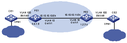
Figure 1-5 Network diagram for VPLS configuration of back-to back PEs (1)
III. Configuration procedure
& Note:
The VPLS service processor card is on slot 5 on PE1 and PE2, and the common interface card is on slot 4.
1) Configure PE1
# Configure the Router ID used to advertise OSPF routing information. Generally, the interface address of both MPLS LSR-ID and Loopback0 can be configured with the same IP address.
[PE1] router id 5.6.7.8
# Configure MPLS LSR-ID. Enable MPLS and MPLS LDP globally.
[PE1] mpls lsr-id 5.6.7.8
[PE1] mpls
[PE1] mpls ldp
# Configure a 32-bit Loopback address, which is used to create LSP.
[PE1] interface loopback0
[PE1 -LoopBack0] ip address 5.6.7.8 32
# Configure a public VLAN, add a port to it, configure an IP address for the interface. Then, enable MPLS and MPLS LDP on the interface.
[PE1] vlan 10
[PE1-vlan10] port GigabitEthernet 4/1/1
[PE1-vlan10] interface vlan 10
[PE1-vlan-interface10] ip address 10.10.10.10 24
[PE1-vlan-interface10] mpls
[PE1-vlan-interface10] mpls ldp enable
# Configure OSPF to set up routes.
[PE1] ospf
[PE1-ospf-1] area 0
[PE1-ospf-1-area-0.0.0.0] network 5.6.7.8 0.0.0.0
[PE1-ospf-1-area-0.0.0.0] network 10.10.10.10 0.0.0.255
[PE1-ospf-1-area-0.0.0.0] quit
[PE1-ospf-1] import-route direct
[PE1-ospf-1] quit
# Configure a LDP remote peer (PE2) to set up LDP session.
[PE1] mpls ldp remote-peer 1
[PE1-mpls-remote1] remote-ip 1.2.3.4
# Enable L2VPN globally.
[PE1] mpls l2vpn
# Configure a VPLS instance and VSI-ID (VPN-ID). Enter VSI-LDP view to configure the IP address of PE2.
[PE1] vsi test static
[PE1-vsi-test] pwsignal ldp
[PE1-vsi-test-ldp] vsi-id 500
[PE1-vsi-test-ldp] peer 1.2.3.4
[PE1-vsi-test-ldp] quit
# Configure a private VLAN, add a port to it, and bind a VSI instance.
[PE1] vlan 100
[PE1-vlan-100] port Ethernet 6/1/48
[PE1-vlan-100] interface vlan 100
[PE1-vlan-interface100] l2 binding vsi test access-mode ethernet
# Enable VLAN-VPN on the port of the private network.
[PE1] interface Ethernet 6/1/48
[PE1-Ethernet6/1/48] vlan-vpn enable
# Configure user-defined flow template, and ACL redirection rule to allow for MPLS packets with VPLS labels.
[PE1] flow-template user-defined slot 4 ethernet-protocol vlanid
[PE1] acl number 4000
[PE1-acl-link-4000] rule 0 permit mpls l2label-range ingress any egress any
[PE1-acl-link-4000] quit
# Define user flow template in port view and configure redirection rule to redirect VPLS packets back from the public network to the VPLS service processor card and specify the VLAN ID of the redirection flow.
[PE1] interface GigabitEthernet4/1/1
[PE1-GigabitEthernet4/1/1] flow-template user-defined
[PE1-GigabitEthernet4/1/1] traffic-redirect inbound link-group 4000 rule 0 slot 5 10 join-vlan
Note that, if a common interface card whose model is suffixed with “B” is seated slot 4 and not all the eight label ranges corresponding to the rule are assigned, you need to perform the following operations to prevent the flow in other label ranges not matched from being passed to the CPU.
# Configure an ACL redirection rule to deny the MPLS packets with VPLS labels.
[PE1] acl number 4001
[PE1-acl-link-4001] rule 1 deny mpls l2label-range ingress any egress any
# Apply the ACL in port view.
[PE1] interface GigabitEthernet4/1/1
[PE1-GigabitEthernet4/1/1] packet-filter inbound link-group 4001 rule 1
2) Configure PE2
# Configure the Router ID used to advertise OSPF routing information. Generally, the interface address of both MPLS LSR-ID and Loopback0 can be configured with the same IP address.
[PE2] router id 1.2.3.4
# Configure MPLS LSR-ID. Enable MPLS and MPLS LDP globally.
[PE2] mpls lsr-id 1.2.3.4
[PE2] mpls
[PE2] mpls ldp
# Configure a 32-bit Loopback address, which is used to create LSP.
[PE2] interface loopback0
[PE2 -LoopBack0] ip address 1.2.3.4 32
# Configure a public VLAN, add a port to it, configure the IP address for the interface. Then, enable MPLS and MPLS LDP on the interface.
[PE2] vlan 10
[PE2-vlan10] port GigabitEthernet 4/1/1
[PE2-vlan10] interface vlan 10
[PE2-vlan-interface10] ip address 10.10.10.11 24
[PE2-vlan-interface10] mpls
[PE2-vlan-interface10] mpls ldp enable
# Configure OSPF to set up routes.
[PE2] ospf
[PE2-ospf-1] area 0
[PE2-ospf-1-area-0.0.0.0] network 1.2.3.4 0.0.0.0
[PE2-ospf-1-area-0.0.0.0] network 10.10.10.11 0.0.0.255
[PE2-ospf-1-area-0.0.0.0] quit
[PE2-ospf-1] import-route direct
[PE2-ospf-1] quit
# Configure a LDP remote peer (PE1) to set up LDP session.
[PE2] mpls ldp remote-peer 1
[PE2-mpls-remote2] remote-ip 5.6.7.8
# Enable L2VPN globally.
[PE2] mpls l2vpn
# Configure a VPLS instance and VSI-ID (VPN-ID). Enter VSI-LDP view to configure the IP address for PE1.
[PE2] vsi test static
[PE2-vsi-test] pwsignal ldp
[PE2-vsi-test-ldp] vsi-id 500
[PE2-vsi-test-ldp] peer 5.6.7.8
[PE2-vsi-test-ldp] quit
# Configure a private VLAN, add a port to it, and bind a VSI instance.
[PE2] vlan 100
[PE2-vlan-100] port Ethernet 6/1/48
[PE2-vlan-100] interface vlan 100
[PE2-vlan-interface100] l2 binding vsi test access-mode ethernet
# Enable VLAN-VPN on the port of the private network.
[PE2] interface Ethernet 6/1/48
[PE2-Ethernet6/1/48] vlan-vpn enable
# Configure user-defined flow template, and ACL redirection rule to allow for MPLS packets with VPLS labels.
[PE2] flow-template user-defined slot 4 ethernet-protocol vlanid
[PE2] acl number 4000
[PE2-acl-link-4000] rule 0 permit mpls l2label-range ingress any egress any
[PE2-acl-link-4000] quit
# Define user flow template in port view and configure redirection rule to redirect VPLS packets back from the public network to the VPLS service processor card and specify the VLAN ID of the redirect flow.
[PE2] interface GigabitEthernet4/1/1
[PE2-GigabitEthernet4/1/1] flow-template user-defined
[PE2-GigabitEthernet4/1/1] traffic-redirect inbound link-group 4000 rule 0 slot 5 10 join vlan
Note that, if a common interface card whose model is suffixed with “B” is seated in slot 4 and not all the eight label ranges corresponding to the rule are assigned, you need to perform the following operations to prevent the flow in other label ranges not matched from being passed to the CPU.
# Configure an ACL redirection rule to deny the MPLS packets with VPLS labels.
[PE1] acl number 4001
[PE1-acl-link-4001] rule 1 deny mpls l2label-range ingress any egress any
# Apply the ACL in port view.
[PE1] interface GigabitEthernet4/1/1
[PE1-GigabitEthernet4/1/1] packet-filter inbound link-group 4001 rule 1
1.4.2 VPLS Basic Configuration Example (2)
I. Network requirements
l The VPLS packet encapsulation mode is Ethernet between PE-A and PE-B, VLAN between PE-B and PE-C, and VLAN between PE-C and PE-A.
l Private networks access VPLS network from PE-A through Ethernet network while from PE-B and PE-C through VLAN network.
l The VPN service processor card is on slot 6 on PE-A, PE-B, and PE-C.
l Configure a Layer 2 VPN to implement VPLS services so that CE-A, CE-B, and CE-C can communicate with each other at Layer 2.
II. Network diagram
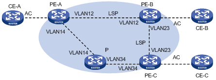
Figure 1-6 Network diagram for VPLS basic configuration (2)
III. Configuration procedure
1) Configure PE-A
# Configure the LSR-ID and enable MPLS, MPLS LDP, and MPLS L2VPN globally.
<PE-A> system-view
[PE-A] mpls lsr-id 1.1.1.1
[PE-A] mpls
[PE-A] mpls ldp
[PE-A] mpls l2vpn
# Create public network VLAN 12, configure the VLAN interface, and then enable MPLS and MPLS LDP for the VLAN interface.
[PE-A] vlan 12
[PE-A-vlan12] interface vlan-interface 12
[PE-A-Vlan-interface12] ip address 192.168.12.1 24
[PE-A-Vlan-interface12] mpls
[PE-A-Vlan-interface12] mpls ldp enable
[PE-A-Vlan-interface12] quit
# Configure a Loopback interface, Its IP address is used for the Router-ID.
[PE-A] interface LoopBack 0
[PE-A-LoopBack0] ip address 1.1.1.1 32
[PE-A-LoopBack0] quit
# Enable OSPF and advertise the routes of the interfaces.
[PE-A] ospf
[PE-A-ospf-1] area 0
[PE-A-ospf-1-area-0.0.0.0] network 192.168.12.0 0.0.0.255
[PE-A-ospf-1-area-0.0.0.0] network 192.168.14.0 0.0.0.255
[PE-A-ospf-1-area-0.0.0.0] network 1.1.1.1 0.0.0.0
[PE-A-ospf-1-area-0.0.0.0] quit
# Configure an ACL redirection rule to permit VPLS packets. Configure a user-defined flow template and apply it to the public network interface, so that VPLS packets from the public network are redirected to the VPN service processor card.
[PE-A] acl number 4000
[PE-A-acl-link-4000] rule 0 permit mpls l2lable-range ingress any egress any
[PE-A-acl-link-4000] quit
[PE-A] flow-template user-defined slot 2 ethernet-protocol vlanid
[PE-A] interface GigabitEthernet 2/1/1
[PE-A-GigabitEthernet2/1/1] flow-template user-defined
[PE-A-GigabitEthernet2/1/1] traffic-redirect inbound link-group 4000 rule 0 slot 6 14 join-vlan
[PE-A-GigabitEthernet2/1/1] quit
# Configure an MPLS LDP remote session.
[PE-A] mpls ldp remote-peer 2
[PE-A-mpls-remote2] remote-ip 1.1.1.2
[PE-A-mpls-remote2] quit
# Perform a VPLS instance.
[PE-A] vsi vpls100 static
[PE-A-vsi-vpls100] pwsignal ldp
[PE-A-vsi-vpls100-ldp] vsi-id 100
[PE-A-vsi-vpls100-ldp] peer 1.1.1.2 encapsulation ethernet
[PE-A-vsi-vpls100-ldp] peer 1.1.1.3 encapsulation vlan
[PE-A-vsi-vpls100-ldp] quit
# Bind the VPLS instance to the private VLAN.
[PE-A] vlan 100
[PE-A-vlan100] interface vlan-interface 100
[PE-A-Vlan-interface100] l2 binding vsi vpls100 access-mode ethernet
[PE-A-Vlan-interface100] quit
# Add Ethernet 4/1/1 to VLAN 100. Enable VLAN-VPN on Ethernet 4/1/1.
[PE-A] interface Ethernet 4/1/1
[PE-A-Ethernet4/1/1] port access vlan 100
[PE-A-Ethernet4/1/1] vlan-vpn enable
2) Configure the other PE devices
The configurations required on the other PE devices are similar to those on PE-A and are therefore omitted.
3) Configure the P device
The following gives only the configurations required on the P device. The detailed configuration steps are omitted.
l Configure the LSR-ID and enable MPLS and MPLS LDP.
l Create a public VLAN and configure an IP address for the VLAN interface. Then, enable MPLS and MPLS LDP on the interface.
l Configure a Loopback interface. Its IP address is used as the Router-ID.
l Enable OSPF to advertise the routes of the interfaces.
1.4.3 Hierarchical VPLS Configuration Example (via MPLS)
& Note:
In the following example, a card that supports MPLS is called a MPLS card; a card that does not support MPLS is called a non-MPLS card.
I. Network requirements
l NPE1, NPE2, and NPE3 are mesh-connected, forming a VPLS network.
l As an access device on the user side, UPE provides access to NPE1 and NPE2 by primary/backup PW. Users under the UPE can communicate with other users in the VPLS network through NPE1 or NPE2.
II. Network diagram
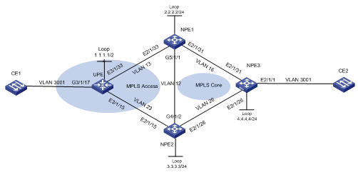
Figure 1-7 Network diagram for H-VPLS configuration (via MPLS)
III. Configuration procedure
& Note:
l In the example, slot 2 holds the public network interface card, slot 5 holds the MPLS card, slot 3 holds the VPLS service card.
l If the access card on the public network side is an MPLS card, you simply need to redirect the VPLS packets to the VPLS service card for redirection, without using the join-vlan parameter.
l If the access card on the public network side is a non-MPLS card, you need to redirect the VPLS packets to the VPLS service card for redirection and use the join-vlan parameter to add the ports to the VLANs.
1) Configure NPE1.
# Configure MPLS globally.
<H3C> system view
[NH3C] sysname NPE1
[NPE1] mpls lsr-id 1.1.1.1
[NPE1] mpls
[NPE1-mpls] quit
[NPE1] mpls ldp
# Configure the public network interface, loopback interface, and routes.
[NPE1] router id 1.1.1.1
[NPE1] interface LoopBack 0
[NPE1-LoopBack0] ip address 1.1.1.1 32
[NPE1-LoopBack0] quit
[NPE1] vlan 16
[NPE1-vlan16] interface vlan-interface 16
[NPE1-Vlan-interface16] ip address 16.16.16.1 24
[NPE1-Vlan-interface16] quit
[NPE1] interface Ethernet 2/1/31
[NPE1-Ethernet2/1/31] port link-type trunk
[NPE1-Ethernet2/1/31] port trunk permit vlan 16
[NPE1-Ethernet2/1/31] undo port trunk permit vlan 1
[NPE1-Ethernet2/1/31] quit
[NPE1] vlan 12
[NPE1-vlan12] interface vlan-interface 12
[NPE1-Vlan-interface12] ip address 12.12.12.1 24
[NPE1-Vlan-interface12] quit
[NPE1] interface GigabitEthernet 5/1/1
[NPE1-GigabitEthernet5/1/1] port link-type trunk
[NPE1-GigabitEthernet5/1/1] port trunk permit vlan 12
[PE1-GigabitEthernet5/1/1] quit
[NPE1] vlan 13
[NPE1-vlan13] quit
[NPE1] interface Ethernet 2/1/33
[NPE1-Ethernet2/1/33] port link-type trunk
[NPE1-Ethernet2/1/33] port trunk permit vlan 13
[NPE1-Ethernet2/1/33] interface vlan-interface 13
[NPE1-Vlan-interface13] ip address 13.13.13.1 24
[NPE1-Vlan-interface13] quit
[NPE1] ospf
[NPE1-ospf-1] area 0
[NPE1-ospf-1-area-0.0.0.0] network 12.12.12.0 0.0.0.255
[NPE1-ospf-1-area-0.0.0.0] network 16.16.16.0 0.0.0.255
[NPE1-ospf-1-area-0.0.0.0] network 13.13.13.0 0.0.0.255
[NPE1-ospf-1-area-0.0.0.0] network 1.1.1.1 0.0.0.0
# Configure interface redirection on the public network side.
[NPE1] flow-template user-defined slot 2 ethernet-protocol vlanid
[NPE1] flow-template user-defined slot 5 ethernet-protocol vlanid
[NPE1] acl number 4000
[NPE1-acl-link-4000] rule 0 permit mpls l2label-range ingress any egress any
[NPE1-acl-link-4000] interface GigabitEthernet 5/1/1
[NPE1-GigabitEthernet5/1/1] flow-template user-defined
[NPE1-GigabitEthernet5/1/1] traffic-redirect inbound link-group 4000 rule 0 slot 3 12
[NPE1-GigabitEthernet5/1/1] quit
[NPE1] interface Ethernet 2/1/31
[NPE1-Ethernet2/1/31] flow-template user-defined
[NPE1-Ethernet2/1/31] traffic-redirect inbound link-group 4000 rule 0 slot 3 16
[NPE1-Ethernet2/1/31] quit
[NPE1] interface Ethernet 2/1/33
[NPE1-Ethernet2/1/33] flow-template user-defined
[NPE1-Ethernet2/1/33] traffic-redirect inbound link-group 4000 rule 0 slot 3 13
# Enable MPLS on public network interfaces.
[NPE1] interface vlan-interface 13
[NPE1-Vlan-interface13] mpls
[NPE1-Vlan-interface13] mpls ldp enable
[NPE1-Vlan-interface13] interface vlan-interface 12
[NPE1-Vlan-interface12] mpls
[NPE1-Vlan-interface12] mpls ldp enable
[NPE1-Vlan-interface12] interface vlan-interface 16
[NPE1-Vlan-interface16] mpls
[NPE1-Vlan-interface16] mpls ldp enable
# Configure MPLS LDP remote sessions.
[NPE1] mpls ldp remote-peer 2
[NPE1-mpls-remote2] remote-ip 2.2.2.2
[NPE1-mpls-remote2] quit
[NPE1] mpls ldp remote-peer 3
[NPE1-mpls-remote3] remote-ip 3.3.3.3
[NPE1-mpls-remote3] quit
[NPE1] mpls ldp remote-peer 6
[NPE1-mpls-remote6] remote-ip 6.6.6.6
# Perform the configuration concerning the VPN instance.
[NPE1] mpls l2vpn
[NPE1] vsi Hvpls static
[NPE1-vsi-Hvpls] pwsignal ldp
[NPE1-vsi-Hvpls-ldp] vsi-id 1
[NPE1-vsi-Hvpls-ldp] peer 2.2.2.2
[NPE1-vsi-Hvpls-ldp] peer 6.6.6.6
[NPE1-vsi-Hvpls-ldp] peer 3.3.3.3 upe
[NPE1-vsi-Hvpls-ldp] quit
[NPE1-vsi-Hvpls] broadcast-restrain 100
[NPE1-vsi-Hvpls] bandwidth 1024000
[NPE1-vsi-Hvpls] quit
# Bind the VPLS instance to the private network interface.
[NPE1] vlan 3001
[NPE1-vlan3001] interface vlan-interface 3001
[NPE1-Vlan-interface3001] l2 binding vsi Hvpls access-mode ethernet
[NPE1-Vlan-interface3001] quit
2) Configure NPE2.
& Note:
l In this part of the example, both slot 2 and slot 4 hold the MPLS cards.
l If the access card on the public network side is an MPLS card, you simply need to redirect the VPLS packets to the VPLS service card for redirection, without using the join-vlan parameter.
l If the access card on the public network side is a non-MPLS card, you need to redirect the VPLS packets to the VPLS service card for redirection and use the join-vlan parameter to add the ports to the VLANs.
# Configure MPLS globally.
<H3C> system view
[H3C] sysname NPE2
[NPE2] mpls lsr-id 2.2.2.2
[NPE2] mpls
[NPE2-mpls] quit
[NPE2] mpls ldp
# Configure the public network interfaces, loopback interface, and routing.
[NPE2] router id 2.2.2.2
[NPE2] interface LoopBack 0
[NPE2-LoopBack0] ip address 2.2.2.2 32
[NPE2-LoopBack0] quit
[NPE2] vlan 26
[NPE2-vlan26] interface vlan-interface 26
[NPE2-Vlan-interface26] ip address 26.26.26.2 24
[NPE2-Vlan-interface26] quit
[NPE2] interface Ethernet 2/1/26
[NPE2-Ethernet2/1/26] port link-type trunk
[NPE2-Ethernet2/1/26] port trunk permit vlan 26
[NPE2-Ethernet2/1/26] undo port trunk permit vlan 1
[NPE2-Ethernet2/1/26] quit
[NPE2] vlan 12
[NPE2-vlan12] interface vlan-interface 12
[NPE2-Vlan-interface12] ip address 12.12.12.2 24
[NPE2-Vlan-interface12] quit
[NPE2] interface GigabitEthernet 4/1/2
[NPE2-GigabitEthernet4/1/2] port link-type trunk
[NPE2-GigabitEthernet4/1/2] port trunk permit vlan 12
[NPE2-GigabitEthernet4/1/2] quit
[NPE2] vlan 23
[NPE2-vlan23] quit
[NPE2] interface Ethernet 2/1/15
[NPE2-Ethernet2/1/15] port link-type trunk
[NPE2-Ethernet2/1/15] port trunk permit vlan 23
[NPE2-Ethernet2/1/15] interface vlan-interface 23
[NPE2-Vlan-interface23] ip address 23.23.23.2 24
[NPE2-Vlan-interface23] quit
[NPE2] ospf
[NPE2-ospf-1] area 0
[NPE2-ospf-1-area-0.0.0.0] network 12.12.12.0 0.0.0.255
[NPE2-ospf-1-area-0.0.0.0] network 26.26.26.0 0.0.0.255
[NPE2-ospf-1-area-0.0.0.0] network 23.23.23.0 0.0.0.255
[NPE2-ospf-1-area-0.0.0.0] network 2.2.2.2 0.0.0.0
# Configure redirection for the public network ports.
[NPE2] flow-template user-defined slot 2 ethernet-protocol vlanid
[NPE2] flow-template user-defined slot 4 ethernet-protocol vlanid
[NPE2] acl number 4000
[NPE2-acl-link-4000] rule 1 permit mpls l2label-range ingress any egress any
[NPE2-acl-link-4000] quit
[NPE2] interface GigabitEthernet 4/1/2
[NPE2-GigabitEthernet4/1/2] flow-template user-defined
[NPE2-GigabitEthernet4/1/2] traffic-redirect inbound link-group 4000 rule 1 slot 5 12
[NPE2-GigabitEthernet4/1/2] quit
[NPE2] interface Ethernet 2/1/26
[NPE2-Ethernet2/1/26] flow-template user-defined
[NPE2-Ethernet2/1/26] traffic-redirect inbound link-group 4000 rule 1 slot 5 26
[NPE2-Ethernet2/1/26] quit
[NPE2] interface Ethernet 2/1/15
[NPE2-Ethernet2/1/15] flow-template user-defined
[NPE2-Ethernet2/1/15] traffic-redirect inbound link-group 4000 rule 1 slot 5 23
[NPE2-Ethernet2/1/15] quit
# Enable MPLS on public network interfaces.
[NPE2] interface vlan-interface 23
[NPE2-Vlan-interface23] mpls
[NPE2-Vlan-interface23] mpls ldp enable
[NPE2-Vlan-interface23] interface vlan-interface 12
[NPE2-Vlan-interface12] mpls
[NPE2-Vlan-interface12] mpls ldp enable
[NPE2-Vlan-interface12] interface vlan-interface 26
[NPE2-Vlan-interface26] mpls
[NPE2-Vlan-interface26] mpls ldp enable
# Configure MPLS LDP remote sessions.
[NPE2] mpls ldp remote-peer 1
[NPE2-mpls-remote1] remote-ip 1.1.1.1
[NPE2-mpls-remote1] quit
[NPE2] mpls ldp remote-peer 3
[NPE2-mpls-remote3] remote-ip 3.3.3.3
[NPE2-mpls-remote3] quit
[NPE2] mpls ldp remote-peer 6
[NPE2-mpls-remote6] remote-ip 6.6.6.6
# Configure the network VPN instance on the private network side.
[NPE2] mpls l2vpn
[NPE2] vsi Hvpls static
[NPE2-vsi-Hvpls] pwsignal ldp
[NPE2-vsi-Hvpls-ldp] vsi-id 1
[NPE2-vsi-Hvpls-ldp] peer 1.1.1.1
[NPE2-vsi-Hvpls-ldp] peer 6.6.6.6
[NPE2-vsi-Hvpls-ldp] peer 3.3.3.3 upe
[NPE2-vsi-Hvpls-ldp] quit
[NPE2-vsi-Hvpls] broadcast-restrain 100
[NPE2-vsi-Hvpls] bandwidth 1024000
[NPE2-vsi-Hvpls] quit
# Bind the VPLS instance to the private network interface.
[NPE2] vlan 3001
[NPE2-vlan3001] interface vlan-interface 3001
[NPE2-Vlan-interface3001] l2 binding vsi Hvpls access-mode ethernet
[NPE2-Vlan-interface3001] quit
3) Configure NPE3.
& Note:
l In this part of the example, slot 2 holds the MPLS card.
l If the access card on the public network side is an MPLS card, you simply need to redirect the VPLS packets to the VPLS service card for redirection, without using the join-vlan parameter.
l If the access card on the public network side is a non-MPLS card, you need to redirect the VPLS packets to the VPLS service card for redirection and use the join-vlan parameter to add the ports to the VLANs.
# Configure MPLS globally.
<H3C> system view
[H3C] sysname NPE3
[NPE3] mpls lsr-id 6.6.6.6
[NPE3] mpls
[NPE3-mpls] quit
[NPE3] mpls ldp
# Configure the public network interfaces, loopback interface, and routing.
[NPE3] router id 6.6.6.6
[NPE3] interface LoopBack 0
[NPE3-LoopBack0] ip address 6.6.6.6 32
[NPE3] vlan 26
[NPE3-vlan26] interface vlan-interface 26
[NPE3-Vlan-interface26] ip address 26.26.26.6 24
[NPE3-Vlan-interface26] quit
[NPE3] interface Ethernet 2/1/26
[NPE3-Ethernet2/1/26] port link-type trunk
[NPE3-Ethernet2/1/26] port trunk permit vlan 26
[NPE3-Ethernet2/1/26] quit
[NPE3] vlan 16
[NPE3-vlan16] interface vlan-interface 16
[NPE3-Vlan-interface16] ip address 16.16.16.6 24
[NPE3-Vlan-interface16] quit
[NPE3] interface Ethernet 2/1/31
[NPE3-Ethernet2/1/31] port link-type trunk
[NPE3-Ethernet2/1/31] port trunk permit vlan 16
[NPE3] ospf
[NPE3-ospf-1] area 0
[NPE3-ospf-1-area-0.0.0.0] network 6.6.6.6 0.0.0.0
[NPE3-ospf-1-area-0.0.0.0] network 26.26.26.0 0.0.0.255
[NPE3-ospf-1-area-0.0.0.0] network 16.16.16.0 0.0.0.255
# Configure redirection for the public network interface.
[NPE3] flow-template user-defined slot 2 ethernet-protocol vlanid
[NPE3] acl number 4000
[NPE3-acl-link-4000] rule 0 permit mpls l2label-range ingress any egress any
[NPE3-acl-link-4000] quit
[NPE3] interface Ethernet 2/1/26
[NPE3-Ethernet2/1/26] flow-template user-defined
[NPE3-Ethernet2/1/26] traffic-redirect inbound link-group 4000 rule 0 slot 10 26
[NPE3-Ethernet2/1/26] interface Ethernet 2/1/31
[NPE3-Ethernet2/1/31] flow-template user-defined
[NPE3-Ethernet2/1/31] traffic-redirect inbound link-group 4000 rule 0 slot 10 16
[NPE3-Ethernet2/1/31]
# Enable MPLS on public network interfaces.
[NPE3] interface vlan-interface 26
[NPE3-Vlan-interface26] mpls
[NPE3-Vlan-interface26] mpls ldp enable
[NPE3-Vlan-interface26] interface vlan-interface 16
[NPE3-Vlan-interface16] mpls
[NPE3-Vlan-interface16] mpls ldp enable
# Configure the MPLS LDP remote session.
[NPE3] mpls ldp remote-peer 2
[NPE3-mpls-remote2] remote-ip 2.2.2.2
[NPE3-mpls-remote2] quit
[NPE3] mpls ldp remote-peer 1
[NPE3-mpls-remote1] remote-ip 1.1.1.1
# Perform VPN-related configuration for the private network side.
[NPE3] mpls l2vpn
[NPE3] vsi Hvpls static
[NPE3-vsi-Hvpls] pwsignal ldp
[NPE3-vsi-Hvpls-ldp] vsi-id 1
[NPE3-vsi-Hvpls-ldp] peer 1.1.1.1
[NPE3-vsi-Hvpls-ldp] peer 2.2.2.2
[NPE3-vsi-Hvpls-ldp] quit
[NPE3-vsi-Hvpls] broadcast-restrain 100
[NPE3-vsi-Hvpls] bandwidth 1024000
# Bind the VPLS instance to the private network interface.
[NPE3] vlan 3001
[NPE3-vlan3001] interface vlan-interface 3001
[NPE3-Vlan-interface3001] l2 binding vsi Hvpls access-mode ethernet
[NPE3-Vlan-interface3001] quit
[NPE3] interface Ethernet 2/1/1
[NPE3-Ethernet2/1/1] port link-type access
[NPE3-Ethernet2/1/1] port access vlan 3001
[NPE3-Ethernet2/1/1] vlan-vpn enable
4) Configure the UPE device.
& Note:
l In the above example, slot 3 holds the MPLS card.
l If the access card on the public network side is an MPLS card, you simply need to redirect the VPLS packets to the VPLS service card for redirection, without using the join-vlan parameter.
l If the access card on the public network side is a non-MPLS card, you need to redirect the VPLS packets to the VPLS service card for redirection and use the join-vlan parameter to add the ports to the VLANs.
# Configure MPLS globally.
<H3C> system view
[H3C] sysname UPE
[UPE] mpls lsr-id 3.3.3.3
[UPE] mpls
[UPE-mpls] quit
[UPE] mpls ldp
# Configure the public network interfaces, loopback interface, and routing.
[UPE] router id 3.3.3.3
[UPE] interface LoopBack 0
[UPE-LoopBack0] ip address 3.3.3.3 32
[UPE] vlan 23
[UPE-vlan23] interface vlan-interface 23
[UPE-Vlan-interface23] ip address 23.23.23.3 24
[UPE-Vlan-interface23] quit
[UPE] interface Ethernet 3/1/15
[UPE-Ethernet3/1/15] port link-type trunk
[UPE-Ethernet3/1/15] port trunk permit vlan 23
[UPE-Ethernet3/1/15] undo port trunk permit vlan 1
[UPE-Ethernet3/1/15] quit
[UPE] vlan 13
[UPE-vlan13] interface vlan-interface 13
[UPE-Vlan-interface13] ip address 13.13.13.3 24
[UPE-Vlan-interface13] quit
[UPE] interface Ethernet 3/1/33
[UPE-Ethernet3/1/33] port link-type trunk
[UPE-Ethernet3/1/33] port trunk permit vlan 13
[UPE-Ethernet3/1/33] undo port trunk permit vlan 1
[UPE-Ethernet3/1/33] quit
[UPE] acl number 4000
[UPE-acl-link-4000] rule 0 permit mpls l2label-range ingress any egress any
[UPE-acl-link-4000] quit
[UPE] interface ethernet 3/1/15
[UPE-Ethernet3/1/15] flow-template user-defined
[UPE-Ethernet3/1/15] traffic-redirect inbound link-group 4000 rule 0 slot 13 23
[UPE-Ethernet3/1/15] quit
[UPE] interface Ethernet 3/1/33
[UPE-Ethernet3/1/33] flow-template user-defined
[UPE-Ethernet3/1/33] traffic-redirect inbound link-group 4000 rule 0 slot 13 13
[UPE-Ethernet3/1/33] quit
# Enable MPLS for the public network interfaces.
[UPE] interface vlan-interface 13
[UPE-Vlan-interface13] mpls
[UPE-Vlan-interface13] mpls ldp enable
[UPE-Vlan-interface13] interface vlan-interface 23
[UPE-Vlan-interface23] mpls
[UPE-Vlan-interface23] mpls ldp enable
[UPE-Vlan-interface23] quit
# Configure the MPLS LDP remote session.
[UPE] mpls ldp remote-peer 1
[UPE-mpls-remote1] remote-ip 1.1.1.1
[UPE-mpls-remote1] quit
[UPE] mpls ldp remote-peer 2
[UPE-mpls-remote2] remote-ip 2.2.2.2
[UPE-mpls-remote2] quit
# Perform the VPN instance-related configuration for the private network side.
[UPE] mpls l2vpn
[UPE] vsi Hvpls static
[UPE-vsi-Hvpls] pwsignal ldp
[UPE-vsi-Hvpls-ldp] vsi-id 1
[UPE-vsi-Hvpls-ldp] peer 1.1.1.1 dual-npe
[UPE-vsi-Hvpls-ldp] peer 2.2.2.2 dual-npe
[UPE-vsi-Hvpls-ldp] quit
[UPE-vsi-Hvpls] broadcast-restrain 100
[UPE-vsi-Hvpls] bandwidth 1024000
[UPE-vsi-Hvpls] quit
# Bind the VPLS instance to the private network interface.
[UPE] vlan 3001
[UPE-vlan3001] interface vlan-interface 3001
[UPE-Vlan-interface3001] l2 binding vsi Hvpls access-mode ethernet
[UPE-Vlan-interface3001]
[UPE-Vlan-interface3001] quit
[UPE] interface Ethernet 3/1/17
[UPE-Ethernet3/1/17] port link-type access
[UPE-Ethernet3/1/17] port access vlan 3001
[UPE-Ethernet3/1/17] vlan-vpn enable
1.4.4 Hierarchical VPLS Configuration Example (via QinQ)
I. Network requriements
1) The devices NPE1, NPE2, and NPE3 are logically mesh-connected through PWs to constitute an MPLS core network. On NPE1 and NPE2, VLAN 100 and VLAN 200 are for access of user data packets while VLAN 2 is for access of BPDUs.
2) In the network diagram, the MTU device needs to run QinQ (VLAN-VPN) and STP or MSTP. In this example, an S9500 switch is used as the MTU device, to which the user devices CE1 and CE2 are attached through ports G4/3/2 and G4/3/1. Packets to be transparently transmitted are data packets tagged VLAN 1000 and VLAN 1001 respectively.
II. Network diagram
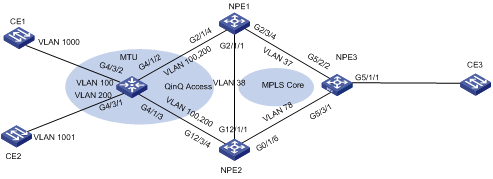
Figure 1-8 Network diagram for H-VPLS configuration (via QinQ)
III. Configuration procedure
1) Configure the MTU device.
# Enable STP globally.
<MTU> system-view
System View: return to User View with Ctrl+Z.
[MTU] stp enable
# Configure the access port for CE1, and enable QinQ on the port.
[MTU] interface GigabitEthernet 4/3/2
[MTU-GigabitEthernet4/3/2] stp disable
[MTU-GigabitEthernet4/3/2] port access vlan 100
[MTU-GigabitEthernet4/3/2] vlan-vpn enable
# Configure the access port for CE2, and enable QinQ on the port.
[MTU] interface GigabitEthernet 4/3/1
[MTU-GigabitEthernet4/3/1] stp disable
[MTU-GigabitEthernet4/3/1] port access vlan 200
[MTU-GigabitEthernet4/3/1] vlan-vpn enable
# Configure the MTU access ports and enable STP on them.
[MTU]interface GigabitEthernet 4/1/2
[MTU-GigabitEthernet4/1/2] port link-type trunk
[MTU-GigabitEthernet4/1/2] port trunk permit vlan 100
[MTU-GigabitEthernet4/1/2] port trunk permit vlan 200
[MTU-GigabitEthernet4/1/2] undo port trunk permit vlan 1
[MTU]interface GigabitEthernet 4/1/3
[MTU-GigabitEthernet4/1/3] port link-type trunk
[MTU-GigabitEthernet4/1/3] port trunk permit vlan 100
[MTU-GigabitEthernet4/1/3] port trunk permit vlan 200
[MTU-GigabitEthernet4/1/3] undo port trunk permit vlan 1
2) Configure NPE1.
# Configure MPLS globally.
<H3C> system view
[H3C] sysname NPE1
[NPE1] mpls lsr-id 1.0.0.13
[NPE1] mpls
[NPE1-mpls] quit
[NPE1] mpls ldp
# Configure the public network interfaces, loopback interface, and routing.
[NPE1] router id 1.0.0.13
[NPE1] interface LoopBack 0
[NPE1-LoopBack0] ip address 1.0.0.13 32
[NPE1] vlan 38
[NPE1-vlan38] interface vlan-interface 38
[NPE1-Vlan-interface38] ip address 192.168.38.3 24
[NPE1-Vlan-interface38] quit
[NPE1] interface GigabitEthernet2/1/1
[NPE1-GigabitEthernet2/1/1] port link-type trunk
[NPE1-GigabitEthernet2/1/1] port trunk permit vlan 38
[NPE1-GigabitEthernet2/1/1] undo port trunk permit vlan 1
[NPE1-GigabitEthernet2/1/1] quit
[NPE1] vlan 37
[NPE1-vlan37] interface vlan-interface 37
[NPE1-Vlan-interface37] ip address 192.168.37.3 24
[NPE1-Vlan-interface37] quit
[NPE1] interface GigabitEthernet2/3/4
[NPE1-GigabitEthernet2/3/4] port link-type trunk
[NPE1-GigabitEthernet2/3/4] port trunk permit vlan 37
[NPE1-GigabitEthernet2/3/4] undo port trunk permit vlan 1
[NPE1-GigabitEthernet2/3/4] quit
[NPE1] ospf
[NPE1-ospf-1] area 0
[NPE1-ospf-1-area-0.0.0.0] network 1.0.0.13 0.0.0.0
[NPE1-ospf-1-area-0.0.0.0] network 192.168.38.0 0.0.0.255
[NPE1-ospf-1-area-0.0.0.0] network 192.168.37.0 0.0.0.255
# Configuration public network port redirection.
[NPE1] flow-template user-defined slot 2 ethernet-protocol vlanid
[NPE1] acl number 4000
[NPE1-acl-link-4000] rule 0 permit mpls l2label-range ingress any egress any
[NPE1-acl-link-4000] interface GigabitEthernet 2/1/1
[NPE1-GigabitEthernet2/1/1] flow-template user-defined
[NPE1-GigabitEthernet2/1/1] traffic-redirect inbound link-group 4000 rule 0 slot 5 38
[NPE1-GigabitEthernet2/1/1] interface GigabitEthernet 2/3/4
[NPE1-GigabitEthernet2/3/4] traffic-redirect inbound link-group 4000 rule 0 slot 5 37
# Enable MPLS on public network interfaces.
[NPE1] interface vlan-interface 38
[NPE1-Vlan-interface38] mpls
[NPE1-Vlan-interface38] mpls ldp enable
[NPE1-Vlan-interface38] interface vlan-interface 37
[NPE1-Vlan-interface37] mpls
[NPE1-Vlan-interface37] mpls ldp enable
# Configure MPLS LDP remote sessions.
[NPE1] mpls ldp remote-peer 2
[NPE1-mpls-remote2] remote-ip 1.0.0.17
[NPE1-mpls-remote2] quit
[NPE1] mpls ldp remote-peer 3
[NPE1-mpls-remote3] remote-ip 1.0.0.18
[NPE1-mpls-remote3] quit
# Perform the configuration concerning the VPN instance.
# Create VPN instance vpn1 for forwarding user data packets (tagged VLAN 1000 in the diagram).
[NPE1] vsi vpn1 static
[NPE1-vsi-vpn1] pwsignal ldp
[NPE1-vsi-vpn1-ldp] vsi-id 1
# Create PW connections for transparent transmission of user data packets between NPE1 and its peers, NPE2 and NPE3.
[NPE1-vsi-vpn1-ldp] peer 1.0.0.18 vc-id 18
[NPE1-vsi-vpn1-ldp] peer 1.0.0.17 vc-id 13 encapsulation vlan
[NPE1-vsi-vpn1-ldp] quit
[NPE1-vsi-vpn1] broadcast-restrain 100
[NPE1-vsi-vpn1] bandwidth 1024000
[NPE1-vsi-vpn1] quit
[NPE1] interface Vlan-interface 100
[NPE1-Vlan-interface100] l2 binding vsi vpn1 access-mode vlan
# Create VPN instance vpn2 for forwarding user data packets (tagged VLAN 1001 in the diagram).
[NPE1] vsi vpn2 static
[NPE1-vsi-vpn2] pwsignal ldp
[NPE1-vsi-vpn2-ldp] vsi-id 2
# Create PW connections for transparent transmission of user data packets between NPE1 and its peers, NPE2 and NPE3.
[NPE1-vsi-vpn2-ldp] peer 1.0.0.18 vc-id 182
[NPE1-vsi-vpn2-ldp] peer 1.0.0.17 vc-id 132 encapsulation vlan
[NPE1-vsi-vpn2-ldp] quit
[NPE1-vsi-vpn2] broadcast-restrain 100
[NPE1-vsi-vpn2] bandwidth 1024000
[NPE1-vsi-vpn2] quit
[NPE1] interface Vlan-interface 200
[NPE1-Vlan-interface200] l2 binding vsi vpn2 access-mode vlan
# Create VPN instance stp for transparent transmission of configuration BPDUs.
[NPE1] vsi stp static
[NPE1-vsi-stp] pwsignal ldp
[NPE1-vsi-stp-ldp]vsi-id 3
# Create a PW connection for transparent transmission of BPDUs between NPE1 and NPE2.
[NPE1-vsi-stp-ldp] peer 1.0.0.18 vc-id 13
[NPE1-vsi-stp-ldp]quit
[NPE1-vsi-stp]quit
[NPE1]vlan 2
[NPE1-vlan2]interface Vlan-interface 2
[NPE1-Vlan-interface2] l2 binding vsi stp access-mode vlan
# Configure a user access port.
[NPE1] interface GigabitEthernet 2/1/4
[NPE1-GigabitEthernet2/1/4] port link-type trunk
[NPE1-GigabitEthernet2/1/4] port trunk permit vlan 2
[NPE1-GigabitEthernet2/1/4] port trunk permit vlan 100
[NPE1-GigabitEthernet2/1/4] port trunk permit vlan 200
[NPE1-GigabitEthernet2/1/4] port trunk pvid vlan 2
[NPE1-GigabitEthernet2/1/4] undo port trunk permit vlan 1
# Disable STP on the MTU access port.
[NPE1-GigabitEthernet2/1/4] stp disable
[NPE1-GigabitEthernet2/1/4] quit
& Note:
l The MTU device is accessed to the H-VPLS network through QinQ. STP or MSTP is enabled on the two ports of the MTU device that interconnect the MTU device with the NPE devices to eliminate BPDU loops. Be sure to disable STP or MSTP on the port of each NPE device that connects the NPE device to the MTU device; otherwise, BPDU cannot be transparently transmitted. To prevent BPDUs from being propagated to other PE devices in the VPLS network, BPDUs and user packets are to be transmitted in different VPLS instances.
l If STP or MSTP has been globally enabled on NPE1 and NPE2, it must be disabled on the MTU access port of the respective NPE device.
3) The configurations on NPE2 and NPE3 are the same as the configurations on NPE1.
1.4.5 VPLS Load Sharing Configuration Example
The S9500 series routing switches support load sharing among multiple VPLS cards. The card level load sharing feature can distribute services evenly to multiple VPLS cards to enhance the VPLS forwarding performance of the system. When a card fails, the services running on that card is automatically switched to a normally operating card. This provides card level service protection to enhance the VPLS service reliability of the system.
Currently, the entire label scope supported by VPLS is divided into eight label ranges, Label0 to Label7, with equal space in each label range. Services of VSI instances are redirected to VPLS cards through two-level mappings.
l Mappings between VSIs and label range IDs:
After a VSI is configured, the system automatically maps the VSI to a label range that currently has the least VSI mappings. A command is provided to allow manual modification of VSI to label range mappings. With this command, you can map a specific VSI to the desired label range ID.
l Mappings between label range IDs VPLS cards:
These mappings are used for public network port redirection. The public network redirection command has two important parameters. One is the redirection rule, namely the VPLS label range (label range ID), and the other is the target VPLS slot number. With this command, you can specify a VPLS card for each label range. Note that the same label range cannot be mapped to more than one VPLS card.
Thus, VPLS load sharing can be implemented by assigning VSI evenly to label ranges, and assigning the label ranges evenly to VPLS cards. When VPLS card becomes faulty or is pulled out, the system immediately chooses a normal working VPLS card that has the least VSI mappings and switches all the services that were running on the faulty or out-of-service card to the new VPLS card. The VSI services corresponding to all the label ranges on the original card are now running on the new card. A certain period of time after the faulty VPLS card recovers or when a good VPLS card is put back in position, the system switches the services back to the original VPLS card.
I. Network requirements
l Two devices are directly interconnected.
l PE1 has four VPLS service cards. It is required that label ranges 0 and 4 be mapped to the VPLS service card on slot 0, label ranges 1 and 5 be mapped to the VPLS service card on slot 3, label ranges 2 and 6 be mapped to the VPLS service card on slot 4, and label ranges 3 and 7 be mapped to the VPLS service card on slot 13. VPLS instances are automatically mapped to label ranges, without the need of manual configuration.
II. Network diagram

Figure 1-9 Network diagram for VPLS load sharing configuration
III. Configuration procedure
1) Configure PE1
# Configure MPLS globally.
<H3C> system view
[H3C] sysname PE1
[PE1] mpls lsr-id 20.0.0.5
[PE1] mpls
[PE1-mpls] quit
[PE1] mpls ldp
# Configure the public network interface, loopback interface, and routing.
[PE1] router id 20.0.0.5
[PE1] interface LoopBack 0
[PE1-LoopBack0] ip address 20.0.0.5 32
[PE1] vlan 25
[PE1-vlan25] interface vlan-interface 25
[PE1-Vlan-interface25] ip address 25.0.0.5 24
[PE1-Vlan-interface25] quit
[PE1] interface GigabitEthernet4/1/8
[PE1-GigabitEthernet4/1/8] port link-type trunk
[PE1-GigabitEthernet4/1/8] port trunk permit vlan 25
[PE1-GigabitEthernet4/1/8] undo port trunk permit vlan 1
[PE1-GigabitEthernet4/1/8] quit
[PE1] ospf
[PE1-ospf-1] area 0
[PE1-ospf-1-area-0.0.0.0] network 20.0.0.5 0.0.0.0
[PE1-ospf-1-area-0.0.0.0] network 25.0.0.0 0.0.0.255
# Configure public network port redirection.
# Define flow templates.
[PE1]flow-template user-defined slot 1 ethernet-protocol vlanid
[PE1]flow-template user-defined slot 10 ethernet-protocol vlanid
# Define a rule for each label range.
[PE1] acl number 4100
[PE1-acl-link-4100] rule 0 permit mpls l2label-range 0 ingress any egress any
[PE1-acl-link-4100] rule 1 permit mpls l2label-range 1 ingress any egress any [PE1-acl-link-4100] rule 2 permit mpls l2label-range 2 ingress any egress any
[PE1-acl-link-4100] rule 3 permit mpls l2label-range 3 ingress any egress any
[PE1-acl-link-4100] rule 4 permit mpls l2label-range 4 ingress any egress any
[PE1-acl-link-4100] rule 5 permit mpls l2label-range 5 ingress any egress any
[PE1-acl-link-4100] rule 6 permit mpls l2label-range 6 ingress any egress any
[PE1-acl-link-4100] rule 7 permit mpls l2label-range 7 ingress any egress any
[PE1-acl-link-4100] quit
# Configure mappings between label ranges and VPLS service cards on the public network port that connects to PE2.
[PE1] interface GigabitEthernet4/1/8
[PE1-GigabitEthernet4/1/8] flow-template user-defined
[PE1-GigabitEthernet4/1/8] traffic-redirect inbound link-group 4100 rule 0 slot 0 25
[PE1-GigabitEthernet4/1/8] traffic-redirect inbound link-group 4100 rule 1 slot 3 25
[PE1-GigabitEthernet4/1/8] traffic-redirect inbound link-group 4100 rule 2 slot 4 25
[PE1-GigabitEthernet4/1/8] traffic-redirect inbound link-group 4100 rule 3 slot 13 25
[PE1-GigabitEthernet4/1/8] traffic-redirect inbound link-group 4100 rule 4 slot 0 25
[PE1-GigabitEthernet4/1/8] traffic-redirect inbound link-group 4100 rule 5 slot 3 25
[PE1-GigabitEthernet4/1/8] traffic-redirect inbound link-group 4100 rule 6 slot 4 25
[PE1-GigabitEthernet4/1/8] traffic-redirect inbound link-group 4100 rule 7 slot 13 25
# Configure an MPLS LDP remote session.
[PE1] mpls ldp remote-peer 1
[PE1-mpls-remote1] remote-ip remote-ip 20.0.0.2
[PE1-mpls-remote1] quit
# Configure parameters related to VPN instances.
# Create VPN instance vpn1.
[PE1] vsi vpn1 static
[PE1-vsi-vpn1] pwsignal ldp
[PE1-vsi-vpn1-ldp] vsi-id 1
[PE1-vsi-vpn1-ldp] peer 20.0.0.2 vc-id 1 encapsulation vlan
[PE1-vsi-vpn1-ldp] quit
[PE1-vsi-vpn1] broadcast-restrain 100
[PE1-vsi-vpn1] bandwidth 1024000
[PE1-vsi-vpn1] quit
[PE1] interface Vlan-interface 100
[PE1-Vlan-interface100] l2 binding vsi vpn1
[PE1-vsi-vpn1]dis this
#
vsi vpn1 static
label-range 0
encapsulation ethernet
broadcast-restrain 100
cos 1
pwsignal ldp
vsi-id 1
peer 20.0.0.2 vc-id 1 encapsulation vlan
#
return
[PE1-vsi-vpn1]
# Create another seven VPLS instances, which are similar to vpn1 and mapped to label ranges 1 through 7 respectively.
2) PE2 can be configured to operate in load sharing mode or to operate with a single VPLS service card based on the actual networking requirement. The configuration steps are omitted here.
& Note:
You can configure a redirection rule for each individual label range or configure a redirection rule for all label ranges. You can apply a redirection rule to different public network ports, but you cannot map the same label range to different VPLS service cards.
1.5 Troubleshooting VPLS
I. Symptom 1
PW is not in UP state.
Solution:
l The LSP tunnel over the public network is not set up for the two ends: verify that the route is available on both ends, you can successfully ping the loopback interface of the peer, and the LDP session is normal.
l Expansion session is abnormal: verify that the commands used to configure the expansion session are executed on both ends, and the configurations are all right.
l The interface of the private VLAN is not bound with the corresponding VPLS instance, or is DOWN: make sure the interface is UP, or the PW to the UPE is UP.
l The parameters for the peer or the MTU value of the VPLS instance is inconsistent: verify that the MTU value configured for the VPLS instance is consistent on both end, and the VC-ID and transmission mode for the peer is also consistent.
l The VPLS service processor card is not in Normal state: make sure that VPLS service processor card is in Normal state.
II. Symptom 2
Packets cannot be forwarded.
Solution:
l The service processor card is not in place: use the display device command to verify that the service processor card is in Normal state.
l The service processor card version is inconsistent with the SRP version: verify the service processor card version.
l The flow template and redirection are not correctly configured on the public side: verify the port for the public network is correctly configured.
III. Symptom 3
Packets get lost during the course of forwarding
Solution:
l Traffic exceeds VPN bandwidth restriction: Increase the VPN bandwidth.
l Broadcast/multicast/unicast traffic exceeds the bandwidth set by broadcast suppression ratio: Modify the broadcast suppression ratio and verify by checking the broadcast suppression of the VPN and the broadcast traffic within the VPN.