- Table of Contents
- Related Documents
-
| Title | Size | Download |
|---|---|---|
| 02-MPLS VLL Configuration | 295.05 KB |
Table of Contents
1.1.2 Introduction to MPLS VLL
1.2 CCC MPLS VLL Configuration
1.2.1 Configuring CCC MPLS VLL
1.2.2 CCC MPLS VLL Configuration Example (1)
1.2.3 CCC MPLS VLL Configuration Example (2)
1.3 Martini MPLS VLL Configuration
1.3.1 Configuring Martini MPLS VLL
1.3.2 Martini MPLS VLL Configuration Example
1.3.3 Martini MPLS VLL Primary/backup PW Configuration Example
1.4 Kompella MPLS VLL Configuration
1.4.1 Configuring Kompella MPLS VLL
1.4.2 Kompella MPLS VLL Configuration Example (1)
1.4.3 Kompella MPLS VLL Configuration Example (2)
1.5 Displaying and Debugging MPLS VLL
Chapter 1 MPLS VLL
When configuring MPLS VLL, go to these sections for information you are interested in:
l Martini MPLS VLL Configuration
l Kompella MPLS VLL Configuration
l Displaying and Debugging MPLS VLL
For MPLS VLL configuration examples, go to the following sections:
l CCC MPLS VLL Configuration Example (1)
l CCC MPLS VLL Configuration Example (2)
l Martini MPLS VLL Configuration Example
l Martini MPLS VLL Primary/backup PW Configuration Example
l Kompella MPLS VLL Configuration Example (1)
l Kompella MPLS VLL Configuration Example (2)
Terms used in this document are listed below:
Table 1-1 Terminology
|
Term |
Full name |
|
AC |
Attachment Circuit |
|
CE |
Customer Edge |
|
FEC |
Forwarding Equivalence Class |
|
FR |
Frame Relay |
|
NPE |
Network Facing PE |
|
PE |
Provider Edge |
|
PW |
Pseudowire |
|
PHP |
Penultimate Hop Popping |
|
UPE |
User Facing PE |
|
VLL |
Virtual Leased Line |
|
VPLS |
Virtual Private LAN Service |
|
VSI |
Virtual Switching Instance |
|
LSP |
Label Switched Path |
1.1 MPLS VLL Overview
1.1.1 Concepts in MPLS VLL
MPLS Virtual Leased Line (MPLS VLL) provides transparently transmission of Layer 2 data of users over an MPLS network. From the users’ perspective, this MPLS network is a Layer switched network through which Layer 2 connections can be set up between different sites. A VLL is a point-to-point virtual connection service provided in the public network. With the VLL, the two sites appear as if they were directly connected through a circuit. However a VLL cannot provide switching service among multiple points directly at the service provider.
1.1.2 Introduction to MPLS VLL
MPLS VLL provides MPLS network-based Layer 2 VPN services. For users, an MPLS network is a Layer 2 switched network, through which Layer 2 connections can be established between network nodes.
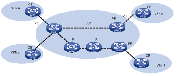
Figure 1-2 Networking diagram of MPLS VLL
MPLS VLL has the following advantages:
l Multiple network layer protocols supported, such as IP, IPv6, IPX, and SNA.
l Powerful extensibility. MPLS VLL only establishes Layer 2 connections, rather than imports and manages the routing information. This eases work load of PE (provider edge) devices and the entire SP (service provider) network remarkably and thus enables SPs to provide more VPNs and accommodate more users.
l Reliability and privacy of user routes. As no user routing information is imported, there is no need for MPLS VLL to obtain and process the information, ensuring the privacy of user routes.
Figure 1-3 illustrates the structure of an MPLS VLL packet.

Figure 1-3 Structure of an MPLS VLL packet
The fields in an MPLS VLL packet are described as follows:
Tunnel label (the outer label) is an MPLS label or a GRE label. It is used to transmit a packet from one PE to anther.
VC label (the inner label) is a lower layer label used to identify the links between PEs and CEs. Packets of MPLS VLLs implemented through circuit cross connect (CCC) do not contain this label.
Data in MPLS VLL can be encapsulated as Ethernet or VLAN packets at the data link layer. At present, data of different nodes in a VPN must be encapsulated as the same type of packets.
1.1.3 Packet Forwarding
In an MPLS VLL, CE, PE, and P operate in the same way as those in a BGP/MPLS VPN. That is, they also forward packets in an MPLS network transparently by using label stacks. To forward packets in an MPLS VLL, tunnels must be established first between PEs (this can be achieved by either manual configuration or signaling protocols). When the interfaces connecting PEs and CEs are up, PEs insert VC labels for packets sent by CE, and then mark them with tunnel labels. On receiving these packets, the remote PEs strip off the tunnel labels and send the packets to the corresponding CEs according to their VC labels.
Figure 1-4 illustrates changes of the label stack of a packet during the forwarding.
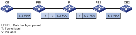
Figure 1-4 Label stack processing of MPLS VLL
1.1.4 Implementation
At present, the official standard for MPLS VLL has not been established yet. However, the PPVPN (Provider-provisioned Virtual Private Network) group of IETF (Internet Engineering Task Force) defines multiple framework drafts, two of which are commonly used. They are known as Martini draft and Kompella draft. Till May, 2005, they are depicted in the following documents respectively:
l draft-martini-l2circuit-trans-mpls-09.txt
l draft-kompella-ppvpn-l2vpn-02.txt
Martini draft defines the way to implement MPLS VLL by establishing point-to-point links. Here, LDP (Label Distribution Protocol) is used as the signaling protocol to exchange VC labels. This kind of MPLS VLLs is known as Martini MPLS VLLs.
Kompella draft defines how to establish MPLS VLLs in MPLS networks through end-to-end (CE-to-CE) connections. At present, BGP (border gateway protocol) is used as the signaling protocol to propagate the information about Layer 2 reachability and VC labels. Such MPLS VLLs are known as Kompella MPLS VLLs.
Also, you can establish MPLS VLLs without signaling protocols. In this case, MPLS VLL services are provided through statically configured VC labels. An example of this is CCC, which implement MPLS VLLs through static configuration.
Table 1-2 describes the features and implementation ways of the above three types of MPLS VLLs.
Table 1-2 Features and implementation ways of the three types of MPLS VLLs
|
VPN type |
Implementation |
Feature |
|
CCC |
Configures static LSPs to implement MPLS VLL. You must manually configure two LSPs (for sending and receiving packets respectively) for each CCC connection node by node (including PEs and Ps). The configured LSPs can only be used to transmit packets of the corresponding CCC connections. |
Data is transmitted through packets with single-layer labels. LSPs are used exclusively. No signaling is needed to transmit the Layer 2 VPN information. Only MPLS forwarding is required. In this way, CEs of different SPs can be interconnected easily. |
|
Martini |
Uses extended LDP as the signaling to transmit the VC information. Uses VC-TYPE and VC-ID to identify VCs. VC-TYPE indicates the encapsulation type of data link layer, and VC-ID uniquely identifies a VC. PEs connecting CEs exchange VC labels through LDPs. They bind the corresponding CEs through VC-IDs. |
Local switching like CCC is not available. An LSP can be shared by multiple VCs. |
|
Kompella |
Similar to Layer 3 BGP/MPLS VPN defined in RFC2547. PEs discover Layer 2 VPN nodes automatically through IBGP sessions established between them. They also propagate the VPN information. Labels are distributed in the form of label blocks, which enables multiple connections being assigned tags simultaneously. The size of a tag block is determined by CE Range (user-configurable). VPN-target is used to differentiate VPNs. |
Users can assign extra labels to VPNs for future use. This eases the configuration work loads of VPN deployment and capacity expansion. VPN-target is used to identify VPNs. This brings great flexibility for VPN networking. Connections between CEs are not concerned. This type of MPLS VLL is implemented by dividing the entire SP network into different VPNs and numbering these CEs in the VPNs. To establish a connection between two CEs, you need to set the local CE ID and the remote CE ID on the PE, and specify the Circuit ID assigned for the connection by the local CE. |
& Note:
l You also can configure LSPs without P devices.
l If a VLL-enabled port is bound with user-defined flow template, the flow template must contain a VLAN field.
![]() Caution:
Caution:
l MPLS VLL does not support NDP transparent transmission.
l It is not recommended to bind VLLs on the default VLAN interface.
l Martini VLL and Kompella VLL modes support multiport access mode, while CCC does not support this.
1.2 CCC MPLS VLL Configuration
1.2.1 Configuring CCC MPLS VLL
Follow these steps to configure CCC MPLS VLL:
|
To do... |
Use the command... |
Remarks |
|
Enter system view |
system-view |
— |
|
Configure LASR-ID |
mpls lsr-id ip-address |
Required |
|
Enable MPLS |
mpls |
Required |
|
Create the egress for the static LSP |
static-lsp egress lsp-name l2vpn incoming-interface vlan-interface vlan-id in-label in-label |
Required. Before configuring a CCC connection, you need to configure two static LSPs between the two PEs and all P routers in between for bidirectional packets. Refer to corresponding sections in the command manual for more information about these commands and corresponding undo commands. |
|
Create the ingress for the static LSP |
static-lsp ingress lsp-name l2vpn nexthop next-hop-addr out-label out-label |
|
|
Create the transit for the static LSP |
static-lsp transit lsp-name l2vpn incoming-interface vlan-interface vlan-id in-label in-label nexthop next-hop-addr out-label out-label |
|
|
Quit MPLS view and enter system view |
quit |
— |
|
Enable MPLS VLL |
mpls l2vpn |
Required |
|
Establish local CCC connection |
ccc ccc-connection-name interface vlan-interface vlan-id out-interface vlan-interface vlan-id |
Required. Two types of CCC connections exist: local CCC connection and remote CCC connection. A local CCC connection is established between two local CEs. It can be switched directly by the PE without being configured a static LSP. A remote CCC connection is established between the local CE and a remote CE. The two CEs are attached to different PEs. In this case, you need to configure two static LSPs for bidirectional packets transmitted between the two PEs. |
|
Establish remote CCC connection |
ccc ccc-connection-name interface vlan-interface vlan-id transmit-lsp transmit-lsp-name receive-lsp receive-lsp-name |
![]() Caution:
Caution:
l In VLL, you can configure only one virtual circuit for each VLAN interface.
l VLL supports VLAN interfaces only. When you configure a VLL on a VLAN interface, data is encapsulated as Ethernet packets by default.
l You must use cards with the suffix CA (such as LSB2FT48CA) for the P devices and PE devices at the access sides of CCC public/private network.
l You can configure only one VLAN on the access side of each VPN private network. Each VLAN can contain only one interface, and IGMP and IGMP Snooping cannot be enabled in any of the VLANs configured on the interface. If IGMP and IGMP Snooping are enabled in some of the VLANs configured on the interface, IGMP packets cannot be transparently transmitted in the VPN.
l You must configure two static LSPs for each remote CCC connection. Two CCC connections cannot share one static LSP.
l A static LSP used by a remote CCC connection cannot be used for other purposes (such as carrying IP packets and BGP/MPLS VPN packets). When you configure a static LSP for a CCC connection, the next hop must be the IP address from which the ARP packets are learnt.
l CCC does not support multiport access of private network.
1.2.2 CCC MPLS VLL Configuration Example (1)
I. Network requirements
CEs and the corresponding PEs shown in Figure 1-5 are interconnected through their GigabitEthernet ports. Data is encapsulated as Ethernet packets at the data link layer. A local connection is required between CE-A and CE-B, and a remote connection between CE-A and CE-C.
II. Network diagram
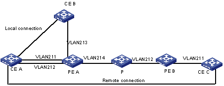
Figure 1-5 Network diagram for CCC MPLS VLL (1)
III. Configuration procedure
1) Configure PE-A.
# Enable MPLS globally.
[H3C] mpls lsr-id 1.1.1.1
[H3C] mpls
# Enable MPLS VLL globally.
[H3C] mpls l2vpn
# Configure VLAN 211.
[H3C] vlan 211
[H3C-vlan211] port gigabitethernet 2/1/1
[H3C-Vlan211] interface vlan-interface 211
[H3C-Vlan-interface211] quit
# Configure VLAN 212.
[H3C] vlan 212
[H3C-vlan212] port gigabitethernet 2/1/2
[H3C-vlan212] interface vlan-interface 212
[H3C-Vlan-interface212] quit
# Configure VLAN 213.
[H3C] vlan 213
[H3C-vlan213] port gigabitethernet 2/1/3
[H3C-vlan213] interface vlan-interface 213
[H3C-Vlan-interface213] quit
# Enable MPLS on the interface of VLAN 214.
[H3C] vlan 214
[H3C-vlan214] port gigabitethernet 2/1/4
[H3C-vlan214] quit
[H3C] interface vlan-interface 214
[H3C-Vlan-interface214] ip address 5.5.5.1 24
[H3C-Vlan-interface214] mpls
[H3C-Vlan-interface214] quit
# Configure the local connection.
[H3C] ccc local-connection interface vlan-interface 211 out-interface vlan-interface 213
# Configure a static LSP, with the out-label of 100 and the egress interface being the interface of VLAN 214.
[H3C] mpls
[H3C-mpls] static-lsp ingress PEA-PEB l2vpn nexthop 5.5.5.2 out-label 100
# Configure a static LSP, with the in-label of 211 and the ingress interface being the interface of VLAN 214.
[H3C-mpls] static-lsp egress PEB-PEA l2vpn incoming-interface vlan-interface 214 in-label 211
# Configure the remote connection.
[H3C] ccc remote-connection interface vlan-interface 212 transmit-lsp PEA-PEB receive-lsp PEB-PEA
2) Configure PE-B.
# Enable MPLS globally.
[H3C] mpls lsr-id 10.0.0.1
[H3C] mpls
# Enable MPLS VLL globally.
[H3C] mpls l2vpn
# Configure VLAN 211.
[H3C] vlan 211
[H3C-vlan211] port gigabitethernet 2/1/1
[H3C] interface vlan-interface 211
[H3C-Vlan-interface211] quit
# Enable MPLS on the interface of VLAN 212.
[H3C] vlan 212
[H3C-vlan212] port gigabitethernet 2/1/2
[H3C-vlan212] quit
[H3C] interface Vlan-interface 212
[H3C-Vlan-interface212] ip address 6.6.6.1 24
[H3C-Vlan-interface212] mpls
# Configure a static LSP, with the out-label of 200 and the egress interface being the interface of VLAN 212.
[H3C-mpls] static-lsp ingress PEB-PEA l2vpn nexthop 6.6.6.2 out-label 200
# Configure a static LSP, with the in-label of 101 and the ingress interface being the interface of VLAN 212.
[H3C-mpls] static-lsp egress PEA-PEB l2vpn incoming-interface vlan-interface 212 in-label 101
# Configure the remote connection.
[H3C] ccc remote-connection interface vlan-interface 211 transmit-lsp PEB-PEA receive-lsp PEA-PEB
3) Configure P.
[H3C] mpls lsr-id 10.0.0.2
[H3C] mpls
[H3C] vlan 214
[H3C-vlan214] port gigabitethernet 2/1/1
[H3C-vlan214] quit
[H3C] interface Vlan-interface 214
[H3C-Vlan-interface214] ip address 5.5.5.2 24
[H3C-Vlan-interface214] mpls
[H3C] vlan 212
[H3C-vlan212] port gigabitethernet 2/1/2
[H3C-vlan212] quit
[H3C] interface Vlan-interface 212
[H3C-Vlan-interface212] ip address 6.6.6.2 24
[H3C-Vlan-interface212] mpls
# Configure a static LSP, with the in-label of 100, the ingress interface being the interface of VLAN 214, the out-label of 101, and the egress interface being the interface of VLAN 212.
[H3C-mpls] static-lsp transit PEA-PEB l2vpn incoming-interface vlan-interface 214 in-label 100 nexthop 6.6.6.1 out-label 101
# Configure a static LSP, with the in-label of 200, the ingress interface being the interface of VLAN 212, the out-label of 211, and the egress interface being the interface of VLAN 211.
[H3C-mpls] static-lsp transit PEB-PEA l2vpn incoming-interface vlan-interface 212 in-label 200 nexthop 5.5.5.1 out-label 211
![]() Caution:
Caution:
Following must be met to make a local CCC connection to go up:
l The interfaces of the two CE are physically up.
l The encapsulation types of the interfaces of the two CEs are the same and are supported by the MPLS VLL.
l For Layer 2 connections with the MPLS VLL being VLAN encapsulation, the VLAN IDs of the interfaces of the two CEs can either be the same or different. However, if a trunk is configured between the CEs and the PEs on both sides, the VLAN IDs of the interfaces of the two CEs must be the same.
1.2.3 CCC MPLS VLL Configuration Example (2)
I. Network requirements
l PE-A, PE-B, PE-C, and the P device constitute an MPLS domain.
l Configure a remote CCC connection between PE-A and PE-B so that CE-A1 and CE-B can communicate at Layer 2. Configure a CCC connection between PE-A and PE-C through the P device, so that CE-A2 and CE-C can communicate at Layer 2.
II. Network diagram
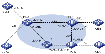
Figure 1-6 Network diagram for CCC MPLS VLL (2)
III. Configuration procedure
1) Configure PE-A
# Configure the LSR-ID. Enable MPLS and MPLS L2VPN.
<PE-A> system-view
[PE-A] mpls lsr-id 1.1.1.1
[PE-A] mpls
[PE-A] mpls l2vpn
# Create public network VLAN 12, configure a VLAN interface, and then enable MPLS for the VLAN interface.
[PE-A] vlan 12
[PE-A-vlan12] interface vlan-interface 12
[PE-A-Vlan-interface12] ip address 192.168.12.1 24
[PE-A-Vlan-interface12] mpls
[PE-A-Vlan-interface12] quit
# Configure static LSPs in MPLS view.
[PE-A] mpls
[PE-A-mpls] static-lsp ingress A-ingress l2vpn nexthop 192.168.12.2 out-label 821
[PE-A-mpls] static-lsp egress A-egress l2vpn incoming-interface Vlan-interface 12 in-label 812
[PE-A-mpls] quit
# Create a private VLAN and a CCC connection.
[PE-A] vlan 4012
[PE-A-vlan4012] interface vlan-interface 4012
[PE-A-Vlan-interface4012] quit
[PE-A] ccc AB-connection interface Vlan-interface 4012 transmit-lsp A-ingress receive-lsp A-egress
[PE-A] interface GigabitEthernet 3/1/1
[PE-A-GigabitEthernet3/1/1] port trunk permit vlan 4012
2) Configure other PE devices
The configurations required on the other PE devices are similar to those on PE-A and are therefore omitted.
3) Configure the P device
# Configure the LSR-ID and enable MPLS (configuration steps are omitted).
# Create a public VLAN for each connected PE and assign an IP address for the VLAN interface. Then, enable MPLS and MPLS LDP on the interface. Configure a Loopback interface. Its IP address is used as the Router-ID (configuration steps are omitted).
# Configure static LSP in MPLS view.
<P> system-view
[P-mpls] static-lsp transit P l2vpn incoming-interface Vlan-interface34 in-label 843 nexthop 192.168.14.1 out-label 814
1.3 Martini MPLS VLL Configuration
1.3.1 Configuring Martini MPLS VLL
Follow these steps to configure Martini MPLS VLL:
|
To do... |
Use the command... |
Remarks |
|
|
Enter system view |
system-view |
— |
|
|
Configure the LSR-ID |
mpls lsr-id lsr-id |
Required |
|
|
Enable MPLS |
mpls |
Required |
|
|
Configure the LDP remote peer |
mpls ldp remote-peer index |
Required. Before configuring the connection, you need to enable LDP on each router and each port of the public network along the connection and configure the LDP remote peer on the peer PE. For details, refer to the LDP Configuration section in MPLS Configuration. |
|
|
Enable MPLS VLL |
mpls l2vpn |
Required |
|
|
Enter VLAN interface view or port view |
VLAN interface view |
interface vlan-interface vlan id |
— |
|
GE/10GE port view |
interface GigabitEthernet interface-number |
— |
|
|
Create a Martini MPLS VLL virtual connection |
In VLAN interface view |
mpls l2vc ip-address vc-id [ preferred-path peer tnl-address ] encapsulation { ethernet | vlan } [ primary | backup ] [ multi-port ] [ mtu mtu ] |
Required To configure a Martini MPLS VLL in VLAN interface view on a PE, you need to provide the IP address (lsr-id) of the peer PE, the VC ID, and the encapsulation type. The combination of the IP address and the VC ID must be unique on the PE. The default MTU is 1500 bytes. |
|
In GE/10GE port view |
mpls l2vc ip-address vc-id [ preferred-path peer tnl-address ] vlan vlan-id encapsulation { ethernet | vlan } [ mtu mtu ] |
To configure a Martini MPLS VLL in port view on a PE, you need to provide the IP address (lsr-id) of the peer PE, the VC ID, the PW encapsulation type, and a VLAN ID. The combination of the IP address and the VC ID must be unique on the PE, and the VLAN ID must be unique in the configuration on the same port. The default MTU is 1500 bytes. |
|
|
Return to system view |
quit |
— |
|
|
Enter VLAN view |
interface vlan-interface vlan id |
— |
|
|
Manually switch the Martini MPLS VLL virtual connection on the VLAN interface (primary or backup) |
mpls l2vc manual-switch [ primary | backup ] |
Optional |
|
|
Return to system view |
quit |
— |
|
|
In system view, restore the primary connections for all Martini MPLS VLL virtual connection configured |
mpls l2vc manual-restore |
Optional |
|
|
In system view, enable the primary connection auto-restore function for Martini MPLS VLL virtual connections |
mpls l2vc auto-restore delay-time delay-time |
Optional The auto-restore function is disabled by default. |
|
|
Display the information about Martini MPLS VLL virtual connections |
display mpls l2vc [ interface { GigabitEthernet interface-number [ vlan vlan-id ] | vlan-interface vlan-id } | verbose ] display mpls l2vc protection [ interface vlan-interface vlan-id ] |
Optional Available in any view |
|
Note the following:
l During the Martini VLL configuration, if you specify the tunnel destination address, you must specify the 32-bit loopback address of the peer PE as the tunnel destination address; if you do not specify the tunnel destination address, the LSR-ID of the peer PE will be used as the tunnel destination address.
l You must use cards with the suffix CA (such as LSB2FT48CA) on the public network access sides when configuring Martini MPLS VLL; you can use cards with the suffix C or CA on the private network access side.
l VLL configured on a VLAN interface supports single-port or multi-port VLAN access private VLANs. If the encapsulation type is Ethernet access, the port link type for the private VLAN is Access; if the encapsulation type is VLAN access, the port link type for the private VLAN is Trunk. It is not recommended to use Hybrid as the port link type for the private VLAN. The user access mode across the PW connection must be the same.
l For single-port access Martini VLL configuration, there can be only one VLAN at the access side of each VPN, each VLAN can comprise only one interface, and IGMP or IGMP Snooping must not be enabled in any VLAN on this interface; if IGMP or IGMP Snooping is enabled in any VLAN on this interface, IGMP messages cannot be transparently transmitted in this VPN.
l Multiport access Martini VLL does not support VLANs that contain hybrid inserted cards or aggregated ports. On the same VLAN interface, the access mode of the primary and backup virtual connection must be the same, both single-port access or both multi-port access. For a multi-port access private network VLAN, the encapsulation type of all the ports in the VLAN must be the same.
l Currently only GE/10GE cards suffixed with CA support Martini VLL configuration in port view (XP4CA cards and WAN cards, such as ATM, E1/T1 and CPOS, do not support this configuration). Only one port is allowed at the access side of each VPN, no duplicate VLAN ID configuration is allowed on the port, and this port must belong to the VLAN in configuration. Make sure the STP is disabled on the port. The Martini VLL configuration cannot be made on a port in hybrid insertion configuration or an aggregation port. Other configurations, such other VLL connections, IGMP, and IGMP snooping, cannot be made on the specified VLAN interface; otherwise these configurations will not work normally. To allow normal operation of other services configured on the VLAN interface, you need to remove the Martini VLL configuration made on the port.
l Currently only Martini VLLs configured on a VLAN interface support the primary/backup VC mode, while port-based Martini VLLs do not support this.
l LSB1XP4CA0 cards do not support the multi-port VLL feature.
l Interface cards configured for ACL redirection in port groups (such as XP4B) cannot be used as non-MPLS intermixing cards.
l The MTU value set in Martini VLL configuration does not affect the actual MTU of the link.
l If you use the mpls l2vc manual-restore command to manually restore primary connections for the MPLS VLL virtual connections on the device, the device will automatically disable the primary connection auto-restore function.
l With the primary connection auto-restore function enabled on the device, you can still use the mpls l2vc manual-restore command to manually switch the MPLS VLL virtual connection on the specified VLAN interface. In this case, if the primary L2VC flapping occurs, after the primary virtual connection resumes normal, the MPLS VLL virtual connection will switch to the primary L2VC automatically.
1.3.2 Martini MPLS VLL Configuration Example
I. Network requirements
CEs shown in Figure 1-7 are in the same VLAN as the corresponding PEs resides in. A remote connection is required between CE-A and CE-B.
II. Network diagram

Figure 1-7 Network diagram for Martini MPLS VLL
III. Configuration procedure
1) Configure PE-A.
# Configure the LSR-ID. Enable MPLS, LDP, and MPLS VLL.
[H3C-A] mpls lsr-id 192.1.1.1
[H3C-A] mpls
[H3C-A-mpls] quit
[H3C-A] mpls ldp
[H3C-A] mpls l2vpn
# Configure VLAN 212.
[H3C-A] vlan 212
[H3C-A-vlan212] port gigabitethernet 2/1/2
[H3C-A-vlan212]interface vlan-interface 212
[H3C-A-Vlan-interface212] quit
# Configure VLAN 21.
[H3C-A] vlan 21
[H3C-A-vlan21] port gigabitethernet 2/1/1
[H3C-A-vlan21] quit
[H3C-A] interface Vlan-interface 21
[H3C-A-Vlan-interface21] ip address 168.1.1.1 255.255.0.0
[H3C-A-Vlan-interface21] mpls
[H3C-A-Vlan-interface21] mpls ldp enable
# Configure an IP address for the Loopback interface, which is used as the Router ID.
[H3C-A] interface loopback 0
[H3C-A-LoopBack0] ip address 192.1.1.1 255.255.255.255
# Enable OSPF.
[H3C-A] ospf 1
[H3C-A-ospf-1] area 0.0.0.0
[H3C-A-ospf-1-area-0.0.0.0] network 192.1.1.1 0.0.0.0
[H3C-A-ospf-1-area-0.0.0.0] network 168.1.1.1 0.0.255.255
# Configure the LDP Remote Peer.
[H3C-A] mpls ldp remote-peer 1
[H3C-A-remote-peer-1] remote-ip 192.1.1.2
# Configure a Martini MPLS VLL connection.
[H3C-A] interface vlan-interface 212
[H3C-A-Vlan-interface212] mpls l2vc 192.1.1.2 20 encapsulation ethernet
2) Configure PE-B.
# Configure the LSR-ID. Enable MPLS, MPLS LDP, and MPLS VLL.
[H3C-B] mpls lsr-id 192.1.1.2
[H3C-B] mpls
[H3C-B-mpls] quit
[H3C-B] mpls ldp
[H3C-B] mpls l2vpn
# Configure VLAN 22.
[H3C-B] vlan 22
[H3C-B-vlan22] port gigabitethernet 2/1/1
[H3C-B-vlan22] interface Vlan-interface 22
[H3C-B-Vlan-interface22] ip address 169.1.1.1 255.255.0.0
[H3C-B-Vlan-interface22] mpls
[H3C-B-Vlan-interface22] mpls ldp enable
# Configure VLAN 212.
[H3C-B] vlan 212
[H3C-B-vlan212] port gigabitethernet 2/1/2
[H3C-B-vlan212] interface vlan-interface 212
[H3C-B-Vlan-interface212] quit
# Configure an IP address for the Loopback interface, which is used as the LSR-ID.
[H3C-B] interface loopback 0
[H3C-B-LoopBack0] ip address 192.1.1.2 255.255.255.255
# Enable OSPF.
[H3C-B] ospf 1
[H3C-B-ospf-1] area 0.0.0.0
[H3C-B-ospf-1-area-0.0.0.0] network 192.1.1.2 0.0.0.0
[H3C-B-ospf-1-area-0.0.0.0] network 169.1.0.0 0.0.255.255
# Configure the LDP Remote Peer.
[H3C-B] mpls ldp remote-peer 1
[H3C-B-mpls-remote1] remote-ip 192.1.1.1
# Configure a Martini MPLS VLL connection.
[H3C-B] interface vlan-interface 212
[H3C-B-Vlan-interface212] mpls l2vc 192.1.1.1 20 encapsulation ethernet
3) Configure P.
# Configure the LSR-ID. Enable MPLS, and LDP.
[H3C-P] mpls lsr-id 192.1.1.3
[H3C-P] mpls
[H3C-P-mpls] quit
[H3C-P] mpls ldp
# Configure an IP address for the Loopback interface and use it as the LSR-ID.
[H3C-P] interface loopback 0
[H3C-P-LoopBack0] ip address 192.1.1.3 255.255.255.255
[H3C-P-LoopBack0] quit
# Configure the VLAN interface.
[H3C-P] vlan 21
[H3C-P-vlan21] port gigabitethernet 2/1/1
[H3C-P-vlan21] quit
[H3C-P] interface Vlan-interface 21
[H3C-P-Vlan-interface21] mpls
[H3C-P-Vlan-interface21] mpls ldp enable
[H3C-P-Vlan-interface21] ip address 168.1.1.2 255.255.0.0
[H3C-P-Vlan-interface21] quit
[H3C-P] vlan 22
[H3C-P-vlan22 port gigabitethernet 2/1/2
[H3C-P-vlan22] quit
[H3C-P] interface Vlan-interface 22
[H3C-P-Vlan-interface22] mpls
[H3C-P-Vlan-interface22] mpls ldp enable
[H3C-P-Vlan-interface22] ip address 169.1.1.2 255.255.0.0
# Enable OSPF.
[H3C-P] ospf 1
[H3C-P-ospf-1] area 0.0.0.0
[H3C-P-ospf-1-area-0.0.0.0] network 168.1.0.0 0.0.255.255
[H3C-P-ospf-1-area-0.0.0.0] network 169.1.0.0 0.0.255.255
[H3C-P-ospf-1-area-0.0.0.0] network 192.1.1.3 0.0.0.0
![]() Caution:
Caution:
Following must be met to make an LDP Layer 2 VPN to go up:
l The interfaces of the two CEs are physically up.
l Two LSP tunnels, which are opposite in direction, exist between two PEs.
l The encapsulation types of interfaces of the two CEs are the same and are supported by the MPLS VLL.
l It is recommended that the VLANs on PE A and PE B which are connected to the CEs be consistent.
l LDP remote sessions exist between PEs and are in Operational state.
l To establish a tunnel, routes to the peer PE are necessary. So you need to configure interior gateway protocol (IGP) on each router along the path, such as OSPF.
1.3.3 Martini MPLS VLL Primary/backup PW Configuration Example
I. Network requirements
l The CEs are connected through VLAN. A remote connection is established between PE2 and PE1, PE2 and PE3, respectively.
l On VLAN101, the virtual interface of PE2, configure a primary virtual connection to PE1 and a backup virtual connection to PE3. Enable manual primary/backup switchover on VLAN101.
l In system view, restore the connection mode to primary.
l In system view, enable the primary connection auto-restore function.
II. Network diagram
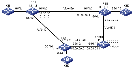
Figure 1-8 Network diagram for configuring Martini MPLS VLL primary/backup PW
III. Configuration procedure
1) Configure PE1
# Configure LSR ID and enable MPLS, LDP and MPLS VLL globally.
[PE1] mpls lsr-id 1.1.1.1
[PE1] mpls
[PE1-mpls] quit
[PE1] mpls ldp
[PE1] mpls l2vpn
# Configure the Loopback interface address to serve as the Router ID.
[PE1]interface LoopBack 0
[PE1-LoopBack0]ip address 1.1.1.1 255.255.255.255
# Configure public VLAN10 and enable MPLS.
[PE1] vlan 10
[PE1-vlan10] interface vlan 10
[PE1-Vlan-interface10] ip address 10.10.10.1 255.255.255.0
[PE1-Vlan-interface10] mpls
[PE1-Vlan-interface10] int g5/1/1
[PE1-GigabitEthernet5/1/1] port access vlan 10
# Create a static LSP from PE1 and PE2.
[PE1] mpls
[PE1-mpls] static-lsp ingress 1to2 destination 2.2.2.2 32 nexthop 10.10.10.2 out-label 3
[PE1-mpls] static-lsp egress 2to1 incoming-interface Vlan-interface10 in-label 3
# Configure the peer relationship with PE2 so that the LDP remote session can be established between them.
[PE1] mpls ldp remote-peer 1
[PE1-mpls-remote1] remote-ip 2.2.2.2
# Configure Martini MPLS VLL connection.
[PE1] int g5/2/1
[PE1-GigabitEthernet5/2/1] port link-type trunk
[PE1-GigabitEthernet5/2/1] port trunk permit vlan 101
[PE1-GigabitEthernet5/2/1] vlan 101
[PE1-vlan101] interface Vlan-interface 101
[PE1-Vlan-interface101] mpls l2vc 2.2.2.2 1101 encapsulation ethernet primary
[PE1-Vlan-interface101] quit
[PE1]
2) Configure PE2
# Configure LSR ID and enable MPLS, LDP and MPLS VLL globally.
[PE2] mpls lsr-id 2.2.2.2
[PE2] mpls
[PE2-mpls] quit
[PE2] mpls ldp
[PE2] mpls l2vpn
# Configure the Loopback interface address to serve as the Router ID.
[PE2] interface LoopBack 0
[PE2-LoopBack0] ip address 2.2.2.2 255.255.255.255
# Configure public network VLAN 10 and VLAN 50, and enable MPLS.
[PE2]vlan 10
[PE2-vlan10] interface vlan 10
[PE2-Vlan-interface10] ip address 10.10.10.2 255.255.255.0
[PE2-Vlan-interface10] mpls
[PE2-Vlan-interface10] interface g5/1/1
[PE2-GigabitEthernet5/1/1]port access vlan 10
[PE2-GigabitEthernet5/1/1]vlan 50
[PE2-vlan50]interface vlan 50
[PE2-Vlan-interface50] ip address 50.50.50.2 255.255.255.0
[PE2-Vlan-interface50] mpls
[PE2-Vlan-interface50] quit
[PE2]
# Create a static LSP from PE2 to PE1, PE2 to PE3, respectively.
[PE2] mpls
[PE2-mpls]static-lsp ingress pe2-pe3 destination 3.3.3.3 32 nexthop 50.50.50.1 out-label 50
[PE2-mpls]static-lsp egress pe3-pe2 incoming-interface Vlan-interface50 in-label 180
[PE2-mpls]static-lsp ingress 2to1 destination 1.1.1.1 32 nexthop 10.10.10.1 out-label 3
[PE2-mpls]static-lsp egress 1to2 incoming-interface Vlan-interface10 in-label 3
# Configure the peer relationship with PE1 and PE3 so that the LDP remote session can be established between them.
[PE2] mpls ldp remote-peer 0
[PE2-mpls-remote0]remote-ip 3.3.3.3
[PE2-mpls-remote0]mpls ldp remote-peer 1
[PE2-mpls-remote1]remote-ip 1.1.1.1
# Configure Martini MPLS VLL connection.
[PE2]interface g5/2/1
[PE2-GigabitEthernet5/2/1] port link-type trunk
[PE2-GigabitEthernet5/2/1] port trunk permit vlan 101
[PE2-GigabitEthernet5/2/1] vlan 101
[PE2-vlan101]interface Vlan-interface 101
[PE2-Vlan-interface101]mpls l2vc 1.1.1.1 1101 encapsulation ethernet primary
[PE2-Vlan-interface101]mpls l2vc 3.3.3.3 101 encapsulation ethernet backup
[PE2-Vlan-interface101]quit
[PE2]
3) Configure PE3
# Configure LSR ID and enable MPLS, LDP and MPLS VLL globally.
[PE3] mpls lsr-id 3.3.3.3
[PE3] mpls
[PE3-mpls] quit
[PE3] mpls ldp
[PE3] mpls l2vpn
# Configure the Loopback interface address to serve as the Router ID.
[PE3]interface LoopBack 0
[PE3-LoopBack0] ip address 3.3.3.3 255.255.255.255
# Configure VLAN 70 and enable MPLS.
[PE3] vlan 70
[PE3-vlan70] interface vlan 70
[PE3-Vlan-interface70] ip address 70.70.70.2 255.255.255.0
[PE3-Vlan-interface70] mpls
[PE3-Vlan-interface70] interface g5/1/1
[PE3-GigabitEthernet5/1/1] port link-type trunk
[PE3-GigabitEthernet5/1/1] port trunk permit vlan 70
# Create a static LSP from PE3 to PE2.
[PE3]mpls
[PE3-mpls]static-lsp egress pe2-pe3 incoming-interface Vlan-interface70 in-label 3
[PE3-mpls]static-lsp ingress pe3-pe2 destination 2.2.2.2 32 nexthop 70.70.70.1 out-label 170
# Configure the peer relationship with PE2 so that the LDP remote session can be established between them.
[PE3]mpls ldp remote-peer 1
[PE3-mpls-remote1]remote-ip 2.2.2.2
# Configure Martini MPLS VLL connection.
[PE3]interface g5/1/13
[PE3-GigabitEthernet5/1/13] port link-type trunk
[PE3-GigabitEthernet5/1/13] port trunk permit vlan 101
[PE3-GigabitEthernet5/1/13] vlan 101
[PE3-vlan101]interface Vlan-interface 101
[PE3-Vlan-interface101] mpls l2vc 2.2.2.2 101 encapsulation ethernet
[PE3-Vlan-interface101]q
[PE3]
4) Configure the P device
# Configure LSR ID and enable MPLS and LDP globally.
[P] mpls lsr-id 4.4.4.4
[P] mpls
[P-mpls] quit
[P] mpls ldp
# Configure the Loopback interface address to serve as the Router ID.
[P] interface LoopBack0
[P-LoopBack0] ip address 4.4.4.4 255.255.255.255
# Configure VLAN 70 and enable MPLS.
[P]vlan 70
[P-vlan70] interface vlan 70
[P-Vlan-interface70] ip address 70.70.70.1 255.255.255.0
[P-Vlan-interface70] mpls
[P-Vlan-interface70] interface g4/1/18
[P-GigabitEthernet 4/1/18] port link-type trunk
[P-GigabitEthernet 4/1/18] port trunk permit vlan 70
[P-GigabitEthernet 4/1/18]q
[P]vlan 50
[P-vlan50] interface vlan 50
[P-Vlan-interface50] ip address 50.50.50.1 255.255.255.0
[P-Vlan-interface50] mpls
[P-Vlan-interface50] interface g4/1/17
[P-GigabitEthernet 4/1/17] port link-type trunk
[P-GigabitEthernet 4/1/17] port trunk permit vlan 50
# Configure a transit LSP from PE2 to PE3 and a transit LSP from PE3 to PE2 on the P device.
[P] mpls
[P-mpls] static-lsp transit pe2-pe3 incoming-interface Vlan-interface50 in-label 50 nexthop 70.70.70.2 out-label 3
[P-mpls] static-lsp transit pe3-pe2 incoming-interface Vlan-interface70 in-label 170 nexthop 50.50.50.2 out-label 180
5) Manually switch the primary/backup virtual connection on VLAN 101, the virtual interface of PE2.
# Display the information about Martini MPLS VLL virtual connection.
[PE2] display mpls l2vc interface Vlan-interface 101
Interface: Vlan-interface101 State: up, Service: VLL
VC-ID: 1101, VC State: (p)up,
Peer Ip Address: 1.1.1.1 primary
Encapsulation: vlan
Group ID: Local 0, Remote 0,
VC Label: Local 32768, Remote 33015,
MTU:Local 1500, Remote 0
Tunnel Type: LSP, Tunnel Destination: 1.1.1.1, Tunnel Index: 31746,
AC: up, LDP Session: up
VC-ID: 101, VC State: (b)up,
Peer Ip Address: 3.3.3.3 backup
Encapsulation: vlan
Group ID: Local 0, Remote 0,
VC Label: Local 32769, Remote 33015,
MTU:Local 1500, Remote 0
Tunnel Type: LSP, Tunnel Destination: 3.3.3.3, Tunnel Index: 31744,
AC: up, LDP Session: up
# Switch the Martini MPLS VLL virtual connection to backup.
[PE2] interface Vlan-interface 101
[PE2-Vlan-interface101] mpls l2vc manual-switch backup
[PE2-Vlan-interface101] quit
# Restore the Martini MPLS VLL virtual connection to primary globally.
[PE2] mpls l2vc manual-restore
# In system view, enable the primary connection auto-restore function for Martini MPLS VLL virtual connections.
[PE2] mpls l2vc auto-restore delay-time 12
1.4 Kompella MPLS VLL Configuration
1.4.1 Configuring Kompella MPLS VLL
Follow these steps to configure Kompella MPLS VLL:
|
To do... |
Use the command... |
Remarks |
|
Enter system view |
system-view |
— |
|
Configure the LSR-ID |
mpls lsr-id lsr-id |
Required |
|
Enable MPLS |
mpls |
Required |
|
Enable MPLS VLL globally |
mpls l2vpn |
Required |
|
Perform BGP (border gateway protocol) related configuration. Make sure BGP operates properly and routers can discover routes to other routers. |
Refer to BGP Configuration in the IP Routing Volume. |
Required In a Kompella MPLS VLL, the extended BGP is used as the signaling protocol to distribute VC labels. So, you also need to configure BGP parameters on PEs. As for the MPLS VLL itself, it has no special requirements on the BGP configuration. Note that after the reflection function is enabled in BGP view, the function is enabled on the related VLL peers. To enabled the reflection function for a VLL peer only, you can execute the undo reflect between-clients command in BGP view, through which the unicast routes received from a client are not reflected to other clients. |
|
Enter VLL address family view. |
l2vpn-family |
Required |
|
Activate the peer or peer group. |
peer { group-name | peer-address } enable |
Required By default, only the peers of BGP IPv4 unicast address families are active. The peer groups of other types are deactivated and thus cannot exchange the routing information. |
|
Create a VPN and specify the encapsulation type. |
mpls l2vpn vpn-name [ encapsulation { ethernet | vlan } ] |
Required The default encapsulation type is Ethernet. In the Kompella mode, the encapsulation type of the access side of the private network can be Ethernet access and VLAN access. If you configure the encapsulation type as Ethernet access, the port link type in a private network VLAN is Access type; if you configure the encapsulation type as VLAN access, the port link type in a private network VLAN is Trunk type. It is not recommended to use Hybrid type as the port link type in a private network VLAN. The user access modes of the instance in all the peer PEs must be consistent. |
|
Configure the RD (route distinguisher) of the MPLS VLL |
route-distinguisher route-distinguisher |
Required For an MPLS VLL, you must configure the RD before performing other configurations. An RD cannot be modified once it is configured. The only way to modify a configured RD is to remove the corresponding MPLS VLL and create another one. As for VLL, it is recommended that you assign a unique RD for each VPN. |
|
Configure the VPN-target of the MPLS VLL |
vpn-target vpn-target-ext-community [ import-extcommunity| export-extcommunity | both ] |
Required |
|
Configure the Layer 2 MTU (maximum transmission unit) of the VPN |
mtu mtu |
Optional The same MTU value must be configured for all PEs in the same VPN. |
|
Create a CE or modify the CE Range of an existing CE |
ce name [ id id [ range range ] [ default-offset offset ] ] |
Required Each CE created on a PE needs to uniquely correspond to one actual CE device connected to the PE. You need to specify a unique ID for these CEs. You can also specify the CE Range. It is desired that the CE ID begins with 1 and increases in step of 1. |
|
Enter an existing CE |
ce name |
|
|
Create connections between CEs |
connection [ ce-offset offset ] { interface vlan-interface vlan-id [ multi-port ] } |
Required When planning a VPN, you can specify CE IDs for CEs beginning with 1 and increasing in step of 1, and then establish connections by CE IDs. You can establish connections with CE Offset not provided for simplifying the configuration. In this case, the default CE Offset is used. |
![]() Caution:
Caution:
l You can only change the CE range to a number larger than the existing one. For example, you can change a CE range from 10 to 20, rather than from 10 to 5. The only way to change a CE range to a smaller number is to remove the CE and create a new one.
l You must use cards with suffix CA (such as LSB2FT48CA) on the public/private network access side when configuring Kompella MPLS VLL.
l VLL supports single port or multiport access private VLANs, while the Kompella VLL local connection does not support multiport access.
l Multiport access enabled Kompella VLL does not support VLANs with intermixing ports or aggregated ports.
l Only one VLAN is allowed on the access side of each VPN private network. Each VLAN can contain only one interface. IGMP and IGMP Snooping cannot be enabled in any of the VLANs configured on the interface. If IGMP and IGMP Snooping are enabled on some of the VLANs configured on the interface, IGMP packets cannot be transparently transmitted in the VPN.
l In Kompella MPLS VLL, the encapsulation type on the access side of each private network can be Ethernet access and VLAN access. Ethernet access is the default type. If you configure the encapsulation type as Ethernet access, the port link type in a private network VLAN is Access type; if you configure the encapsulation type as VLAN access, the port link type in a private network VLAN is Trunk type. It is not recommended to use Hybrid type as the port link type in a private network VLAN. The user access modes of the instance in all peer PEs must be consistent.
l In Kompella mode, VPNs are established in the entire SP network. In each VPN, a CE is assigned a CE ID, which must be unique in the VPN. In a VPN, connections cannot be established between CEs with the same CE IDs. In this case, You need to remove the configurations of the CEs with the same CE IDs and configure CE IDs for these CEs again to establish the connections.
l The MTU configured here has no effect on the actual MTU on the link.
1.4.2 Kompella MPLS VLL Configuration Example (1)
I. Network requirements
CEs shown in Figure 1-9 are in the same VLAN as the corresponding PEs resides in. A remote connection is required between CE-A and CE-B.
II. Network diagram

Figure 1-9 Network diagram for Kompella MPLS VLL (1)
III. Configuration procedure
1) Configure PE-A.
# Enable MPLS globally.
[H3C] mpls lsr-id 1.1.1.1
[H3C] mpls
[H3C-mpls] quit
[H3C] mpls ldp
# Configure an IP address for the Loopback interface.
[H3C] interface loopback 0
[H3C-LoopBack0] ip address 1.1.1.1 32
# Enable MPLS VLL globally.
[H3C] mpls l2vpn
# Configure VLAN 212.
[H3C] vlan 212
[H3C-vlan212] port gigabitethernet 2/1/2
[H3C-vlan212] interface vlan-interface 212
[H3C-Vlan-interface212] quit
# Enable MPLS on the interface of VLAN 21.
[H3C] vlan 21
[H3C-vlan21] port gigabitethernet 2/1/4
[H3C-vlan21] quit
[H3C] interface vlan-interface 21
[H3C-Vlan-interface21] ip address 5.5.5.1 24
[H3C-Vlan-interface21] mpls
[H3C-Vlan-interface21] mpls ldp enable
[H3C-Vlan-interface21] mpls ldp transport-ip interface
[H3C-Vlan-interface21] quit
# Configure BGP.
[H3C] bgp 100
[H3C-bgp] group 100 internal
[H3C-bgp] peer 100 connect-interface loopback0
[H3C-bgp] peer 3.3.3.3 group 100
[H3C-bgp] l2vpn-family
[H3C-bgp-af-l2vpn] peer 100 enable
# Create and configure the VPN.
[H3C] mpls l2vpn vpn1 encapsulation ethernet
[H3C-mpls-l2vpn-vpn1] route-distinguisher 100:1
[H3C-mpls-l2vpn-vpn1] vpn-target 100:1
# Create CE1 and configure the corresponding connection.
[H3C-mpls-l2vpn-vpn1] ce ce1 id 1 range 200
[H3C-mpls-l2vpn-vpn1-ce1] connection ce-offset 2 interface vlan-interface 212
[H3C-mpls-l2vpn-vpn1-ce1] quit
# Enable OSPF.
[H3C] ospf 1 router-id 1.1.1.1
[H3C-ospf-1] area 0.0.0.0
[H3C-ospf-1-area-0.0.0.0] network 1.1.1.1 0.0.0.0
[H3C-ospf-1-area-0.0.0.0] network 5.5.5.0 0.0.0.255
2) Configure PE-B.
# Enable MPLS globally.
[H3C] mpls lsr-id 3.3.3.3
[H3C] mpls
[H3C-mpls] quit
[H3C] mpls ldp
# Configure an IP address for the Loopback interface.
[H3C] interface loopback 0
[H3C-LoopBack0] ip address 3.3.3.3 32
# Enable MPLS VLL globally.
[H3C] mpls l2vpn
# Configure VLAN 212.
[H3C] vlan 212
[H3C-vlan212] port gigabitethernet 2/1/2
[H3C-vlan212] interface vlan-interface 212
[H3C-Vlan-interface 212] quit
# Enable MPLS on the interface of VLAN 22.
[H3C] vlan 22
[H3C-vlan22] port gigabitethernet 2/1/4
[H3C-vlan22] quit
[H3C] interface vlan-interface 22
[H3C-Vlan-interface22] ip address 6.6.6.1 24
[H3C-Vlan-interface22] mpls
[H3C-Vlan-interface22] mpls ldp enable
[H3C-Vlan-interface22] mpls ldp transport-ip interface
[H3C-Vlan-interface22] quit
# Configure BGP.
[H3C] bgp 100
[H3C-bgp] group 100 internal
[H3C-bgp] peer 100 connect-interface loopback0
[H3C-bgp] peer 1.1.1.1 group 100
[H3C-bgp] l2vpn-family
[H3C-bgp-af-l2vpn] peer 100 enable
# Create and configure VPN1.
[H3C] mpls l2vpn vpn1 encapsulation ethernet
[H3C-mpls-l2vpn-vpn1] route-distinguisher 100:1
[H3C-mpls-l2vpn-vpn1] vpn-target 100:1
# Create CE2 and configure the corresponding connection.
[H3C-mpls-l2vpn-vpn1] ce ce2 id 2 range 200
[H3C-mpls-l2vpn-vpn1-ce2] connection ce-offset 1 interface vlan-interface 212
[H3C-mpls-l2vpn-vpn1-ce2] quit
# Enable OSPF.
[H3C] ospf 1 router-id 3.3.3.3
[H3C -ospf-1] area 0.0.0.0
[H3C -ospf-1-area-0.0.0.0] network 3.3.3.3 0.0.0.0
[H3C -ospf-1-area-0.0.0.0] network 6.6.6.0 0.0.0.255
3) Configure the P device.
Note that the VLANs on PE A and PE B which are connected to the CEs must be consistent.
1.4.3 Kompella MPLS VLL Configuration Example (2)
I. Network requirements
l PE-A, PE-B, PE-C, and the P device constitute an MPLS domain.
l Configure Kompella MPLS L2VPNs on PE-A, PE-B, and PE-C, and specify the CE range to 10.
l Set up Kompella MPLS VLL connections between PE-A and PE-B and between PE-A and PE-C.
l Configure CE-A1 and CE-B to communicate at Layer 2, and CE-A2 and CE-C to communicate at Layer 2.
II. Network diagram
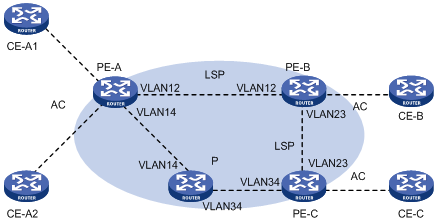
Figure 1-10 Network diagram for Kompella MPLS VLL (2)
III. Configuration procedure
1) Configure PE-A.
# Configure LSR ID and enable MPLS and LDP.
<PE-A> system-view
[PE-A] mpls lsr-id 1.1.1.1
[PE-A] mpls
[PE-A] mpls ldp
# Create public network VLAN 12, configure a VLAN interface, and then enable MPLS and MPLS LDP for the VLAN interface.
[PE-A] vlan 12
[PE-A-vlan12] interface vlan-interface 12
[PE-A-Vlan-interface12] ip address 192.168.12.1 24
[PE-A-Vlan-interface12] mpls
[PE-A-Vlan-interface12] mpls ldp enable
[PE-A-Vlan-interface12] quit
# Configure a Loopback interface. Its IP address is used as the Router-ID and LSR-ID.
[PE-A] interface LoopBack 0
[PE-A-LoopBack0] ip address 1.1.1.1 32
[PE-A-LoopBack0] quit
# Enable OSPF and advertise the routes of the interfaces.
[PE-A] ospf
[PE-A-ospf-1] area 0
[PE-A-ospf-1-area-0.0.0.0] network 192.168.12.0 0.0.0.255
[PE-A-ospf-1-area-0.0.0.0] network 192.168.14.0 0.0.0.255
[PE-A-ospf-1-area-0.0.0.0] network 1.1.1.1 0.0.0.0
[PE-A-ospf-1-area-0.0.0.0] quit
# Enable BGP and configure the BGP peer relationship with PE-B and PE-C, using the loopback interface as the source interface.
[PE-A] bgp 100
[PE-A-bgp] group ibgp internal
[PE-A-bgp] peer 1.1.1.2 group ibgp
[PE-A-bgp] peer 1.1.1.2 connect-interface LoopBack0
[PE-A-bgp] peer 1.1.1.3 group ibgp
[PE-A-bgp] peer 1.1.1.3 connect-interface LoopBack0
# Enable the peer group to exchange BGP routing information.
[PE-A-bgp] l2vpn-family
[PE-A-bgp-af-l2vpn] peer ibgp enable
[PE-A-bgp-af-l2vpn] quit
# Enable MPLS L2VPN.
[PE-A] mpls l2vpn
# Configure a private VLAN, and enter its VLAN interface view.
[PE-A] vlan-vpn
[PE-A] vlan 4000
[PE-A-vlan4000] interface vlan-interface 4000
[PE-A-Vlan-interface4000] quit
# Create a Kompella MPLS L2VPN, specifying the encapsulation type as VLAN. Then specify the RD and RT.
[PE-A] mpls l2vpn k4000 encapsulation vlan
[PE-A-mpls-l2vpn-k4000] route-distinguisher 100:4000
[PE-A-mpls-l2vpn-k4000] vpn-target 100:4000
# Create a CE and configure the corresponding connection.
[PE-A-mpls-l2vpn-k4000] ce PE-A id 1 range 10
[PE-A-mpls-l2vpn-ce-k4000-PE-A] connection ce-offset 1 interface Vlan-interface 4000
2) Configure the other PE devices.
The configurations required on the other PE devices are similar to those on PE-A and are therefore omitted.
3) Configure the P device.
The following gives only the configurations required on the P device. The detailed configuration steps are omitted.
l Configure the LSR-ID, and enable MPLS and MPLS LDP.
l Create a public VLAN and assign an IP address for the VLAN interface. Then, enable MPLS and MPLS LDP on the interface.
l Configure a Loopback interface. Its IP address is used as the Router-ID.
l Enable OSPF and advertise the routes of the interfaces.
1.5 Displaying and Debugging MPLS VLL
|
To do... |
Use the command... |
Remarks |
|
Display information about a CCC MPLS VLL connection |
display ccc [ ccc-name | type [ local | remote ] ] |
Available in any view |
|
Display information about a Martini MPLS VLL connection |
display mpls l2vc [ interface { GigabitEthernet interface-number [ vlan vlan-id ] | vlan-interface vlan-id } | verbose] display mpls l2vc protection [ interface vlan-interface vlan-id ] |
|
|
Display information about a Kompella MPLS VLL connection |
display mpls l2vpn [ vsi-name [ local-ce | remote-ce ] | connection [ vsi-name [ down | remote-ce | up | verbose ] | brief | interface vlan-interface vlan-id ] | forwarding-info { vc-label | interface vlan-interface vlan-id } ] display bgp l2vpn { all | peer | route-distinguisher ASN } |
|
|
Enable debugging for MPLS VLL |
debugging mpls l2vpn { advertisement | all | connections [ interface vlan-interface vlan-id ] | error | event | loadshare | switchover } |
Available in user view |
1.6 Troubleshooting MPLS VLL
Symptom 1: Fail to configure Layer 2 VPN on the VLAN interface.
Solution:
l Check to see if MPLS/BGP VPN, multicast, or VLL is enabled on the VLAN interface. Because you cannot perform Layer 2 VPN configuration on a VLAN interface if MPLS/BGP VPN, multicasting, or VLL is enabled on it.
l Check to see if the VLAN is a super-VLAN or a sub-VLAN. You can perform the Layer 2 VPN configuration only on common VLAN interfaces.
Symptom 2: Fail to ping the peer from one end of a Martini MPLS VLL connection. The VC is down and the Remote value is invalid.
Solution:
l VC state being down indicates the encapsulation types or VC IDs of the two ends are not the same. Make sure the interface types (Access or Trunk) of the two PE interfaces and the VC IDs of the two ends are consistent.
l As for the invalid Remote value, make sure you have configured the Remote parameters and the peer addresses correctly.
Symptom 3: Fail to ping the peer of a Kompella MPLS VLL connection. The Connection is down and the VPN value is null.
Solution:
l VPN value being null indicates the VPN is configured incorrectly. Make sure the VPN configurations (such as RD) of the both ends are consistent, and the connection configurations of the two CEs on both ends are correct.
l Connection being down indicates configurations concerning encapsulation of the two ends are not the same. Make sure the encapsulation types and MTUs configured for the local and remote PE devices are consistent. A connection fails if the encapsulation types configured on the two ends are not the same.
Symptom 4: Fail to ping the peer end of a CCC MPLS VLL connection. The sending and receiving channels are up, so does the link connection.
Solution:
Make sure the in-label and out-label configured on the both ends correspond to each other. If a P device exists, make sure its forwarding connection configuration is correct, and the next hop configured statically is configured.