- Table of Contents
- Related Documents
-
| Title | Size | Download |
|---|---|---|
| 07-MSDP Configuration | 224.96 KB |
1.2.3 Configuring Static RPF Peers
1.2.4 Configuring Originating RP
1.2.5 Configuring SA Caching State
1.2.6 Configuring the Maximum Number of SA Caching
1.2.7 Requesting Source Information of MSDP Peers
1.2.8 Controlling the Source Information Created
1.2.9 Controlling the Source Information Forwarded
1.2.10 Controlling the Received Source Information
1.2.11 Configuring MSDP Mesh Group
1.2.12 Configuring the MSDP Connection Retry Period
1.2.13 Shutting MSDP Peers Down
1.2.14 Clearing MSDP Connections, Statistics and SA Caching Configuration
1.3 Displaying and Maintaining MSDP
1.4 MSDP Configuration Examples
1.4.1 Configuring Static RPF Peers
1.4.3 MSDP Integrated Networking
Chapter 1 MSDP Configuration
When configuring MSDP, go to these sections for information you are interested in:
l Displaying and Maintaining MSDP
1.1 MSDP Overview
1.1.1 Introduction
No ISP would like to forward multicast traffic by RPs of competitors, but do expect to obtain information from the source and distribute it among the members, regardless of the location of the multicast source RP. MSDP is proposed to solve this problem. Multicast source discovery protocol (MSDP) describes interconnection mechanism of multiple PIM-SM domains. It is used is to discover multicast source information in other PIM-SM domains. MSDP allows the RPs of different domains to share the multicast source information, but all these domains must use PIM-SM as their intro-domain multicast routing protocol.
A RP configured with MSDP peer notifies all of its MSDP peers of the active multicast source message in its domain via a source active (SA) message. In this way, multicast source information in a PIM-SM domain is transmitted to another PIM-SM domain.
MSDP peer relationship can be established between RPs in different domains or in a domain, between a RP and a common router, or between common routers. The connection between MSDP peers is a TCP connection.
MSDP makes a PIM-SM domain independent of the RP in another PIM-SM domain. After getting multicast source information in that domain, the receiver here can join directly to the SPT of the multicast source in that domain.
Another application of MSDP is Anycast RP. In a domain, configure a certain interface (usually Loopback interface) on different routers with the same IP address; designate these interfaces as C-RPs; and create MSDP peer relationship among them. After the unicast route convergence, the multicast source can select the nearest RP for registration, and the receiver can also select the nearest RP to add into its RPT. The RPs exchange individual registration source information via MSDP peers. Therefore, every RP knows all multicast sources of the entire domain; and every receiver on each RP can receive multicast data from all the multicast sources in the entire domain.
By initiating registration and RPT joining to the nearest RP, MSDP implements RP load sharing. Once an RP turns invalid, its original registered source and receivers will select another nearest RP, implementing redundant RP backup.
In addition, MSDP only accepts the SA messages from the correct paths and excludes redundant SA messages through RPF check mechanism, and prevents the flooding of SA messages among MSDP peers by configuring Mesh Group.
1.1.2 Working Principle
I. Identifying multicast source and receiving multicast data
As shown in Figure 1-1, the RPs of PIM-SM domains 1, 2 and 3 establish peer relationship between them. Domain 3 contains a group member.
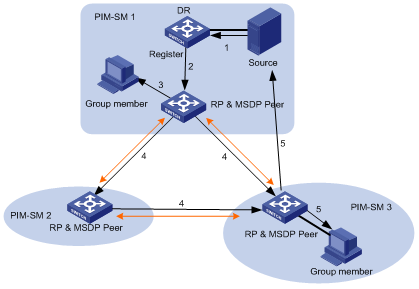
Figure 1-1 MSDP working principles (I)
When the multicast source in domain 1 sends data to the multicast group, the working process of the member in domain 3, from discovering the multicast source to receiving data from the source, includes the following:
The multicast source in PIM-SM domain 1 begins to send datagram.
The DR connected to the multicast source encapsulates the datagram into a Register packet and forward it to the RP in domain 1.
The RP in domain 1 decapsulates the packet and forwards it along the RPT to all the members within the domain. The domain members can choose whether to switch to the SPT.
The RP in domain 1 generates an SA message for the MSDP peers (the RPs in PIM-SM domain 2 and domain 3). The SA message contains multicast source IP address, multicast group address and the address of the RP that generates the message. Besides, the RP in domain 1 encapsulates the first received multicast data into this SA message.
If there is any group member in the domain of an MSDP peer (in the figure, it is PIM-SM domain 3), the RP in this domain sends the multicast data encapsulated in the SA message to group members along the RPT and the join message to multicast source.
After the reverse forwarding path is created, the multicast source data is sent directly to the RP in domain 3, and then the RP forwards the data along the RPT. In this case, the last hop router connected with the group member in domain 3 can choose whether to switch to SPT.
II. Message forwarding and RPF check between MSDP peers
As shown in Figure 1-2, Switch A belongs to domain 1, Switch B, Switch C, and Switch D to domain 2, and Switch E and Switch F to domain 3. MSDP peer relationship is established between them, indicated with bi-directional arrows in the figure. Among them, Mesh Group is created among Switch B, Switch C and Switch D.
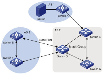
Figure 1-2 MSDP working principles (II)
The SA message forwarding and RPF check among these MSDP peers are illustrated as follows:
If the SA message is from a MSDP peer that is the RP of the multicast source, it is received and forwarded to other peers (for example, from Switch A to Switch B).
If the SA message is from a MSDP peer that has only one peer, it is received (for example, from Switch B to Switch A).
If the SA message is from a static RPF peer, it is received and forwarded to other peers (for example, from Switch D to Switch E).
If the SA message is from a MSDP peer in Mesh Group, it is received and forwarded to the peers outside the Mesh Group (for example, from Switch B to Switch D).
If the SA message is sent from a MSDP peer in the same domain, and the peer is the next hop along the optimal path to the RP in the domain of source, it is received and forwarded to other peers (for example, from Switch E to Switch F).
If the SA message is sent from a MSDP peer in a different domain which is the next autonomous domain along the optimal path to the RP in the domain of source, it is received and forwarded to other peers (for example, Switch D to Switch F).
For other SA messages, they are neither received nor forwarded.
III. Precautions for configuration
The router running MSDP must also run BGP or MBGP. It is recommended to use the same IP address of the MSDP peer with that of the BGP peer or MBGP peer. If neither BGP nor MBGP is in operation, a static RPF peer should be configured.
1.2 MSDP Configuration
Basic configuration tasks of MSDP include
Advanced configuration tasks of MSDP include
l Configuring Static RPF Peers
l Configuring SA Caching State
l Configuring the Maximum Number of SA Caching
l Requesting Source Information of MSDP Peers
l Controlling the Source Information Created
l Controlling the Source Information Forwarded
l Controlling the Received Source Information
l Configuring the MSDP Connection Retry Period
l Clearing MSDP Connections, Statistics and SA Caching Configuration
1.2.1 Enabling MSDP
To configure MSDP, you must enable MSDP first.
Perform the following operation in system view to enable/disable MSDP:
|
To do... |
Use the command... |
|
Enable MSDP and enter MSDP view |
msdp |
|
Clear all MSDP configurations |
undo msdp |
1.2.2 Configuring MSDP Peers
To run MSDP, you need to configure MSDP peers locally.
Perform the following operations in MSDP view to configure MSDP peers:
|
To do... |
Use the command... |
|
Configure MSDP peers |
peer peer-address connect-interface interface-type interface-number |
|
Remove MSDP peer configuration |
undo peer peer-address |
|
Add description to a MSDP peer |
peer peer-address description text |
|
Remove the description |
undo peer peer-address description text |
The command to add description is optional.
If the local router is also in BGP Peer relation with an MSDP peer, the MSDP peer and the BGP peer should use the same IP address.
Neither of any two routers between which MSDP peer relationship has been established must run BGP or MBGP, as long as they have a BGP or MBGP route between them. If no BGP of MBGP route exists between them, you must configure static RPF peers.
1.2.3 Configuring Static RPF Peers
Perform the following operation in MSDP view to configure/remove static RPF peers:
|
To do... |
Use the command... |
|
Configure static RPF peers |
static-rpf-peer peer-address [ rp-policy ip-prefix-name] |
|
Remove static RPF peer configuration |
undo static-rpf-peer peer-address |
By default, no static RPF peer is configured.
& Note:
l The peer command must be configured before the static-rpf-peer command.
l If only one MSDP peer is configured via the peer command, the MSDP peer will be regarded as the static RPF peer.
To configure multiple static RPF peers at the same time, take either of the two methods:
l Using rp-policy parameters universally: Multiple static RPF peers take effect at the same time and SA messages are filtered by the RP addresses contained according to the configured prefix list. If multiple static RPF peers using the same rp-policy parameter are configured, any peer that receives an SA message will forward it to the other peers.
l Not using the rp-policy parameter universally: According to the configuration sequence, only the first static RPF peer whose connection state is UP is activated. All SA messages from the peer will be received and those from other static RPF peers will be discarded. Once the activated static RPF peer turns invalid (for example, the configuration is removed or the connection is interrupted), the following first static RPF peer with UP connection state according to the configuration sequence will assume its role.
1.2.4 Configuring Originating RP
During the creation of SA message, an MSDP peer can be configured to use the IP address of a specified interface as the RP address in its SA message.
Perform the following operation in MSDP view to configure/remove originating RP:
|
To do... |
Use the command... |
|
Configure an MSDP peer to use the IP address of a specified interface as the RP address of its SA message |
originating-rp interface-type interface-number |
|
Remove the above operation |
undo originating-rp |
By default, the RP address in SA message is the one configured by PIM.
1.2.5 Configuring SA Caching State
When SA messages are cached on a router, the new join-in groups can directly access all the active sources and join the corresponding source tree, instead of waiting for the arrival of the next SA message.
Perform the following operation in MSDP view to configure/disable SA caching state:
|
To do... |
Use the command... |
|
Configure SA caching state |
cache-sa-enable |
|
Disable SA caching state |
undo cache-sa-enable |
By default, the router caches the SA state, or rather the (S, G) entry when receiving an SA message.
Some memory is consumed as the join delay of groups is shortened by this configuration.
1.2.6 Configuring the Maximum Number of SA Caching
To prevent Deny of Service (DoS) attacks, you can set the maximum number of SAs cached on the router.
Perform the following operation in MSDP view to configure/restore the maximum number of SA caching:
|
To do... |
Use the command... |
|
Configuring the maximum number of SA caching |
peer peer-address sa-cache-maximum sa-limit |
|
Restore the default configuration |
undo peer peer-address sa-cache-maximum |
By default, the maximum number of SA caching is 2048.
1.2.7 Requesting Source Information of MSDP Peers
When a new group joins, the router will send a SA request message to the specified MSDP peer, and the MSDP peer will respond with the SA messages it caches. If the MSDP peer does not enable the SA caching, the configuration is invalid.
Perform the following operations in MSDP view to request source information of MSDP peers or restore the default configuration:
|
To do... |
Use the command... |
|
Configure the router to send SA request message to the specified MSDP peer when receiving the join message of a group |
peer peer-address request-sa-enable |
|
Restore the default configuration |
undo peer peer-address request-sa-enable |
The SA request message sent by a local RP will get the immediate response about all active sources.
By default, the router does not send SA request message to its MSDP peer when receiving the join message of a group. Instead, it waits for the arrival of SA message of the next period.
1.2.8 Controlling the Source Information Created
I. Filtering the multicast routing entries imported
RP filters the registered sources to control the information of the active sources advertised in SA message. MSDP peers can be configured to only advertise the qualified (S, G) entries in the multicast routing table when creating SA messages, that is, to control the (S,G) entries imported from the multicast routing table to the domain.
Perform the following operations in MSDP view to filter the multicast routing entries imported or remove the configuration:
|
To do... |
Use the command... |
|
Advertise only the (S, G) entries permitted by the ACL |
import-source [ acl acl-number ] |
|
Remove the above configuration |
undo import-source |
By default, only intra-domain sources are advertised in SA messages.
If the import-source command without acl parameter is executed, no source is advertised in SA messages.
II. Filtering SA request messages
Perform the following operations in MSDP view to filter SA request messages or remove the configuration:
|
To do... |
Use the command... |
|
Filter all the SA request messages from a specified MSDP peer |
peer peer-address sa-request-policy |
|
Filter the SA request messages of the groups of a specified MSDP peer permitted by the basic ACL from |
peer peer-address sa-request-policy acl acl-number |
|
Remove the configuration of filtering SA request messages |
undo peer peer-address sa-request-policy |
By default, only the routers which caches SA messages can respond to SA request messages. Routers receive all SA request messages from its MSDP peers.
Multicast group addresses are described in ACL. If no ACL is specified, all SA request messages sent by the corresponding MSDP peer will be ignored. If an ACL is specified, only SA request messages of the groups permitted by the ACL will be processed.
1.2.9 Controlling the Source Information Forwarded
Controlling of source information also includes that of forwarding and receiving source information besides that of creating source information. The outbound filter or time to live (TTL) threshold of SA messages can be used to control the SA message forwarding. By default, all SA messages are forwarded to other MSDP peers.
I. Using MSDP outbound filter
MSDP outbound filter of are functional in:
l Filtering off all the (S, G) entries
l Forwarding only the SA messages permitted by the advanced ACL
Perform the following operations in MSDP view to use MSDP outbound filter to control the source information forwarded:
|
To do... |
Use the command... |
|
Filter off all the SA messages to a specified MSDP peer |
peer peer-address sa-policy export |
|
Forward the SA messages permitted by the advanced ACL to a specified MSDP peer |
peer peer-address sa-policy export acl acl-number |
|
Remove the filtering over the source information forwarded |
undo peer peer-address sa-policy export |
II. Using TTL to filter SA messages with encapsulated data
An SA message with encapsulated data can reach the specified MSDP peer only when the TTL in its IP header is no less than the threshold. Therefore, the forwarding of SA messages with encapsulated data can be controlled by configuring the TTL threshold.
For example, you can set the TTL threshold for intra-domain multicast traffic to 10 if you wish to restrict SA messages with TTL less than or equal to 10 carrying encapsulated data from being propagated. If you set the TTL threshold greater than 10, then they can be propagated to outside.
Perform the following operations in MSDP view to use TTL to filter SA messages with encapsulated data or the remove the configuration:
|
To do... |
Use the command... |
|
Filter off the multicast data encapsulated in the first SA message aiming at a specified MSDP peer |
peer peer-address minimum-ttl ttl |
|
Remove the TTL threshold configuration |
undo peer peer-address minimum-ttl |
The default value of TTL threshold is 0.
1.2.10 Controlling the Received Source Information
Perform the following operations in MSDP view to control the received source information:
|
To do... |
Use the command... |
|
Filter off the SA messages from a specified MSDP peer |
peer peer-address sa-policy import |
|
Receive the SA messages permitted by the advanced ACL from a specified MSDP peer |
peer peer-address sa-policy import acl acl-number |
|
Remove the filtering rule over received source information |
undo peer peer-address sa-policy import |
Similar to MSDP outbound filter in function, MSDP inbound filter controls the received SA messages. By default, the SA messages from all peers are accepted.
1.2.11 Configuring MSDP Mesh Group
Mesh Group is useful when full connection among MSDP peers is required but SA message flooding shall be prevented.
In a Mesh group, SA messages from outside the group are forwarded to other members in the group, but the SA messages from peers inside the group will not be performed with Peer-RPF check or forwarded in the group. In this case, the overflow of SA messages is avoided and Peer-RPF is simplified, as BGP or MBGP is not required between MSDP peers.
Perform the following operations in MSDP view to configure/remove MSDP full connection group:
|
To do... |
Use the command... |
|
Configure an MSDP peer to be a member of an MSDP Mesh Group |
peer peer-address mesh-group name |
|
Delete that member from the Group |
undo peer peer-address mesh-group name |
If an MSDP peer is configured into different mesh groups, only the last configuration is valid.
1.2.12 Configuring the MSDP Connection Retry Period
Perform the following operations in MSDP view to configure/restore the MSDP connection retry period:
|
To do... |
Use the command... |
|
Configuring the MSDP connection retry period |
timer retry seconds |
|
Restore the default value of MSDP connection retry interval |
undo timer retry |
By default, MSDP connection is retried at the interval of 30 seconds.
1.2.13 Shutting MSDP Peers Down
The session between MSDP peers can be cut off and re-activated as needed.
If a session between MSDP peers is cut off, the TCP connection will terminate with no retry effort, but the configuration information will be reserved.
Perform the following operations in MSDP view to shut down/turn up MSDP peers:
|
To do... |
Use the command... |
|
Shut down a specified MSDP peer |
shutdown peer-address |
|
Turn the MSDP peer up |
undo shutdown peer-address |
By default, MSDP peer is enabled.
1.2.14 Clearing MSDP Connections, Statistics and SA Caching Configuration
Perform the following operations in user view to clear MSDP connections, statistics and SA caching configuration:
|
To do... |
Use the command... |
|
Clear a specified TCP connection and reset the counters of all MSDP information |
reset msdp peer peer-address |
|
Clear MSDP peer statistics |
reset msdp statistics [ peer-address ] |
|
Clear cached SA entries of MSDP |
reset msdp sa-cache [ group-address ] |
1.3 Displaying and Maintaining MSDP
I. Displaying and debugging MSDP
|
To do... |
Use the command... |
Remarks |
|
Display the numbers of sources and groups of SA messages from a specified autonomous domain |
display msdp sa-count [ as-number ] |
Available in any view |
|
Display the details of a MSDP peer |
display msdp peer-status [ peer-address ] |
Available in any view |
|
Display the (S, G) state learnt from MSDP peer |
display msdp sa-cache [ group-address | source-address | as-number ] * |
Available in any view |
|
Display MSDP peer state |
display msdp brief |
Available in any view |
|
Enable MSDP debugging |
debugging msdp { all | connect | event | packet | source-active } |
Available in user view |
![]() Caution:
Caution:
The display msdp sa-count command give output only after the cache-sa-enable command is executed.
II. Tracing the transmission path of SA messages on the network
The msdp-tracert command can be used in any view to trace the network path of multicast data from multicast source to destination receiver and locate faults.
Perform the follow operation to trace the transmission path of SA messages on the network:
|
To do... |
Use the command... |
|
Trace the transmission path of SA messages on the network |
msdp-tracert { source-address } { group-address } { rp-address } [ max-hops max-hops ] [ next-hop-info ] [ sa-info ] [ peer-info ] [ skip-hops skip-hops ] * |
Locating information loss and reducing configuration faults can be realized by tracing the network path of the specified (S, G, RP) entries. After the transmission path of SA messages is determined, the overflow of SA messages can be avoided by the correct configuration.
1.4 MSDP Configuration Examples
1.4.1 Configuring Static RPF Peers
I. Network requirements
In the following network environment shown in Figure 1-3, four H3C S9500 series routing switches are in the different PIM-SM domains with no BGP or MBGP running among them.
To enable Switch D to receive the specified source information from PIM-SM domains 1, 2 and 3, you can configure static RPF peers with the rp-policy Argument.
After the configuration is complete, Switch D will only receive SA messages permitted by the corresponding filtering policy from its static RPF peers.
II. Network diagram
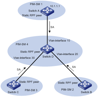
Figure 1-3 Configure static RPF peers
III. Configuration procedure
Configure Switch D as follows:
# Configure Switch A to be a static RPF peer of Switch D.
<SwitchD> system-view
System View: return to User View with Ctrl+Z.
[SwitchD] ip ip-prefix list-a permit 10.10.0.0 16
[SwitchD] msdp
[SwitchD-msdp] peer 10.10.1.1 connect-interface Vlan-interface 10
[SwitchD-msdp] static-rpf-peer 10.10.1.1 rp-policy list-a
[SwitchD-msdp] quit
# Configure Switch B to be a static RPF peer of Switch D.
[SwitchD] ip ip-prefix list-b permit 10.21.0.0 16
[SwitchD] msdp
[SwitchD-msdp] peer 10.21.1.1 connect-interface Vlan-interface 20
[SwitchD-msdp] static-rpf-peer 10.21.1.1 rp-policy list-b
[SwitchD-msdp] quit
# Configure Switch C to be a static RPF peer of Switch D.
[SwitchD] ip ip-prefix list-c permit 10.25.0.0 16
[SwitchD] msdp
[SwitchD-msdp] peer 10.25.1.1 connect-interface Vlan-interface30
[SwitchD-msdp] static-rpf-peer 10.25.1.1 rp-policy list-c
1.4.2 Configuring Anycast RP
I. Network requirements
To configure Anycast RP in the PIM-SM domain, establish MSDP peer relationship between Switch A and Switch B; use the address of Loopback 0 on Switch A and Switch B to send out SA messages; set Loopback 10 on Switch A and Switch B as BSR/RP and configure the Anycast RP address. In this way, when a unicast group member joins, the switch directly connected to the host can originate a join message to the nearest RP in the topology.
& Note:
This example focuses on the configuration of Switch A and Switch B. Configuration performed on Switch E, Switch D and Switch C is omitted as it mainly concerns enabling multicast and enabling PIM-SM on the interfaces.
II. Network diagram
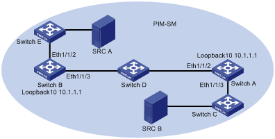
Figure 1-4 Network diagram for Anycast RP configuration
III. Configuration procedure
1) Configure Switch B
# Configure VLAN.
<SwitchB> system-view
System View: return to User View with Ctrl+Z.
[SwitchB] vlan 10
[SwitchB-vlan10] port ethernet1/1/2
[SwitchB-vlan10] quit
[SwitchB] vlan 20
[SwitchB-vlan20] port ethernet1/1/3
[SwitchB-vlan20] quit
# Enable multicast routing.
[SwitchB] multicast routing-enable
# Configure the IP address of interface Loopback 0.
[SwitchB] interface loopback0
[SwitchB-LoopBack0] ip address 10.10.1.1 255.255.255.255
[SwitchB-LoopBack0] quit
# Configure the IP address of interface Loopback 10 and enable IGMP and PIM-SM.
[SwitchB] interface loopback10
[SwitchB-LoopBack10] ip address 10.1.1.1 255.255.255.255
[SwitchB-LoopBack10] igmp enable
[SwitchB-LoopBack10] pim sm
[SwitchB-LoopBack10] quit
# Configure the IP address of VLAN-interface 10 and enable IGMP and PIM-SM.
[SwitchB] interface Vlan-interface10
[SwitchB-Vlan-interface10] ip address 10.10.2.1 255.255.255.0
[SwitchB-Vlan-interface10] igmp enable
[SwitchB-Vlan-interface10] pim sm
[SwitchB-Vlan-interface10] undo shutdown
[SwitchB-Vlan-interface10] quit
# Configure the IP address of VLAN-interface 20 and enable IGMP and PIM-SM.
[SwitchB] interface Vlan-interface20
[SwitchB-Vlan-interface20] ip address 10.10.3.1 255.255.255.0
[SwitchB-Vlan-interface20] igmp enable
[SwitchB-Vlan-interface20] pim sm
[SwitchB-Vlan-interface20] undo shutdown
[SwitchB-Vlan-interface20] quit
# Configure OSPF.
[SwitchB] ospf
[SwitchB-ospf-1] area 0
[SwitchB-ospf-1-area-0.0.0.0] network 10.10.2.0 0.0.0.255
[SwitchB-ospf-1-area-0.0.0.0] network 10.10.3.0 0.0.0.255
[SwitchB-ospf-1-area-0.0.0.0] network 10.1.1.1 0.0.0.0
[SwitchB-ospf-1-area-0.0.0.0] network 10.10.1.1 0.0.0.0
[SwitchB-ospf-1-area-0.0.0.0] quit
[SwitchB-ospf-1] quit
# Configure Switch A as its MSDP peer.
[SwitchB] msdp
[SwitchB-msdp] peer 10.21.1.1 connect-interface loopback 0
# Configure Originating RP.
[SwitchB-msdp] originating-rp loopback0
[SwitchB-msdp] quit
# Configure C-RP and BSR.
[SwitchB] pim
[SwitchB-pim] c-rp loopback 10
[SwitchB-pim] c-bsr loopback 10 30
2) Configure Switch A.
# Configure VLAN.
<SwitchA> system-view
System View: return to User View with Ctrl+Z.
[SwitchA] vlan 10
[SwitchA-vlan10] port ethernet1/1/2
[SwitchA-vlan10] quit
[SwitchA] vlan 20
[SwitchA-vlan20] port ethernet1/1/3
[SwitchA-vlan20] quit
# Enable multicast routing.
[SwitchA] multicast routing-enable
# Configure the IP address of interface Loopback 0.
[SwitchA] interface loopback0
[SwitchA-LoopBack0] ip address 10.21.1.1 255.255.255.255
[SwitchA-LoopBack0] quit
# Configure the IP address of interface Loopback 10 and enable IGMP and PIM-SM.
[SwitchA] interface loopback10
[SwitchA-LoopBack10] ip address 10.1.1.1 255.255.255.255
[SwitchA-LoopBack10] igmp enable
[SwitchA-LoopBack10] pim sm
[SwitchA-LoopBack10] quit
# Configure the IP address of interface VLAN-interface 20 and enable IGMP and PIM-SM.
[SwitchA] interface Vlan-interface20
[SwitchA-Vlan-interface20] ip address 10.21.2.1 255.255.255.0
[SwitchA-Vlan-interface20] igmp enable
[SwitchA-Vlan-interface20] pim sm
[SwitchA-Vlan-interface20] undo shutdown
[SwitchA-Vlan-interface20] quit
# Configure the IP address of VLAN-interface 10 and enable IGMP and PIM-SM.
[SwitchA] interface Vlan-interface10
[SwitchA-Vlan-interface10] ip address 10.21.3.1 255.255.255.0
[SwitchA-Vlan-interface10] igmp enable
[SwitchA-Vlan-interface10] pim sm
[SwitchA-Vlan-interface10] undo shutdown
[SwitchA-Vlan-interface10] quit
# Configure OSPF route.
[SwitchA] ospf
[SwitchA-ospf-1] area 0
[SwitchA-ospf-1-area-0.0.0.0] network 10.21.2.0 0.0.0.255
[SwitchA-ospf-1-area-0.0.0.0] network 10.21.3.0 0.0.0.255
[SwitchA-ospf-1-area-0.0.0.0] network 10.1.1.1 0.0.0.0
[SwitchA-ospf-1-area-0.0.0.0] network 10.21.1.1 0.0.0.0
[SwitchA-ospf-1-area-0.0.0.0] quit
[SwitchA-ospf-1] quit
# Configure Switch B as its MSDP peer.
[SwitchA] msdp
[SwitchA-msdp] peer 10.10.1.1 connect-interface loopback 0
# Configure Originating RP.
[SwitchA-msdp] originating-rp loopback0
[SwitchA-msdp] quit
# Configure C-RP and BSR.
[SwitchA] pim
[SwitchA-pim] c-rp loopback 10
[SwitchA-pim] c-bsr loopback 10 30
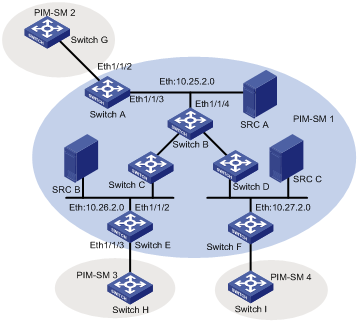
1.4.3 MSDP Integrated Networking
I. Network requirement
In the following network, enable MSDP and configure an Anycast RP in PIM-SM domain 1; establish MSDP peer relationship among RPs across PIM-SM domains; and use MBGP between domains. For the related commands, refer to the part of MBGP configuration examples in MBGP Configuration of the IP Multicast Volume.
II. Network diagram
|
Device |
Interface |
IP Address |
Device |
Interface |
IP Address |
|
Switch A |
Loop0 |
10.25.1.1 |
Switch B |
Loop0 |
10.25.1.2 |
|
|
Loop10 |
10.1.1.1 |
|
|
|
|
Switch C |
Loop0 |
10.26.1.1 |
Switch D |
Loop0 |
10.27.1.1 |
|
Switch E |
Loop0 |
10.26.1.2 |
Switch F |
Loop0 |
10.27.1.2 |
|
|
Loop10 |
10.1.1.1 |
|
Loop10 |
10.1.1.1 |
|
Switch G |
Loop0 |
10.28.1.1 |
Switch H |
Loop0 |
10.29.1.1 |
|
Switch I |
Loop0 |
10.30.1.1 |
|
|
|
Figure 1-5 MSDP integrated networking
III. Configuration procedure
& Note:
The follow procedure details multicast configuration, but briefs router configuration.
1) Configure Switch A
# Configuring VLAN
<SwitchA> system-view
System View: return to User View with Ctrl+Z.
[SwitchA] vlan 10
[SwitchA-vlan10] port ethernet1/1/2
[SwitchA-vlan10] quit
[SwitchA] vlan 30
[SwitchA-vlan30] port ethernet1/1/3
[SwitchA-vlan30] quit
# Enable multicast.
[SwitchA] multicast routing-enable
# Configure the IP address of interface Loopback 0 and enable PIM-SM.
[SwitchA] interface loopback0
[SwitchA-LoopBack0] ip address 10.25.1.1 255.255.255.255
[SwitchA-LoopBack0] pim sm
[SwitchA-LoopBack0] quit
# Configure the IP address of interface Loopback 10 and enable PIM-SM.
[SwitchA] interface loopback10
[SwitchA-LoopBack10] ip address 10.1.1.1 255.255.255.255
[SwitchA-LoopBack10] pim sm
[SwitchA-LoopBack10] quit
# Configure the IP address of VLAN-interface 30 and enable IGMP and PIM-SM.
[SwitchA] interface Vlan-interface30
[SwitchA-Vlan-interface30] ip address 10.25.2.3 255.255.255.0
[SwitchA-Vlan-interface30] igmp enable
[SwitchA-Vlan-interface30] pim sm
[SwitchA-Vlan-interface30] undo shutdown
[SwitchA-Vlan-interface30] quit
# Configure the IP address of VLAN-interface 10 and enable IGMP and PIM-SM.
[SwitchA] interface Vlan-interface10
[SwitchA-Vlan-interface10] ip address 10.25.3.1 255.255.255.0
[SwitchA-Vlan-interface10] igmp enable
[SwitchA-Vlan-interface10] pim sm
[SwitchA-Vlan-interface10] undo shutdown
[SwitchA-Vlan-interface10] quit
# Configure OSPF.
[SwitchA] ospf
[SwitchA-ospf-1] area 0
[SwitchA-ospf-1-area-0.0.0.0] network 10.25.2.0 0.255.255.255
[SwitchA-ospf-1-area-0.0.0.0] network 10.1.1.1 0.0.0.0
[SwitchA-ospf-1-area-0.0.0.0] network 10.25.1.1 0.0.0.0
[SwitchA-ospf-1-area-0.0.0.0] quit
[SwitchA-ospf-1] quit
# Configure BGP.
[SwitchA] bgp 100
[SwitchA-bgp] undo synchronization
[SwitchA-bgp] group in internal
[SwitchA-bgp] peer 10.26.1.2 group in
[SwitchA-bgp] peer 10.27.1.2 group in
[SwitchA-bgp] peer in connect-interface loopback0
[SwitchA-bgp] ipv4-family multicast
[SwitchA-bgp-af-mul] peer in enable
[SwitchA-bgp-af-mul] peer 10.26.1.2 group in
[SwitchA-bgp-af-mul] peer 10.27.1.2 group in
[SwitchA-bgp-af-mul] peer in next-hop-local
[SwitchA-bgp-af-mul] quit
[SwitchA-bgp] group ex external
[SwitchA-bgp] peer 10.28.1.1 group ex as-number 200
[SwitchA-bgp] peer ex next-hop-local
[SwitchA-bgp] peer ex default-route-advertise
[SwitchA-bgp] ipv4-family multicast
[SwitchA-bgp-af-mul] peer ex enable
[SwitchA-bgp-af-mul] peer 10.28.1.1 group ex
[SwitchA-bgp-af-mul] peer ex next-hop-local
[SwitchA-bgp-af-mul] quit
[SwitchA-bgp] quit
# Configure MSDP peer, Mess Group and Originating RP.
[SwitchA] msdp
[SwitchA-msdp] peer 10.28.1.1 connect-interface loopback 0
[SwitchA-msdp] peer 10.26.1.2 connect-interface loopback 0
[SwitchA-msdp] peer 10.27.1.2 connect-interface loopback 0
[SwitchA-msdp] peer 10.26.1.2 mesh-group net
[SwitchA-msdp] peer 10.27.1.2 mesh-group net
[SwitchA-msdp] originating-rp loopback0
[SwitchA-msdp] quit
# Configuring C-RP and BSR.
[SwitchA] pim
[SwitchA-pim] c-rp loopback 10
[SwitchA-pim] c-bsr loopback 0 30
2) Configure Switch E
# Configuring VLAN
<SwitchE> system-view
System View: return to User View with Ctrl+Z.
[SwitchE] vlan 10
[SwitchE-vlan10] port ethernet1/1/2
[SwitchE-vlan10] quit
[SwitchE] vlan 20
[SwitchE-vlan20] port ethernet1/1/3
[SwitchE-vlan20] quit
# Enable multicast.
[SwitchE] multicast routing-enable
# Configure the IP address of interface Loopback 0 and enable PIM-SM.
[SwitchE] interface loopback0
[SwitchE-LoopBack0] ip address 10.26.1.2 255.255.255.255
[SwitchE-LoopBack0] pim sm
[SwitchE-LoopBack0] quit
# Configure the IP address of interface Lookback10 and enable PIM-SM.
[SwitchE] interface loopback10
[SwitchE-LoopBack10] ip address 10.1.1.1 255.255.255.255
[SwitchE-LoopBack10] pim sm
[SwitchE-LoopBack10] quit
# Configure the IP address of VLAN-interface 10 and enable IGMP and PIM-SM.
[SwitchE] interface Vlan-interface10
[SwitchE-Vlan-interface10] ip address 10.26.2.3 255.255.255.0
[SwitchE-Vlan-interface10] igmp enable
[SwitchE-Vlan-interface10] pim sm
[SwitchE-Vlan-interface10] undo shutdown
[SwitchE-Vlan-interface10] quit
# Configure the IP address of VLAN-interface 20 and enable IGMP and PIM-SM.
[SwitchE] interface Vlan-interface20
[SwitchE-Vlan-interface20] ip address 10.26.3.1 255.255.255.0
[SwitchE-Vlan-interface20] igmp enable
[SwitchE-Vlan-interface20] pim sm
[SwitchE-Vlan-interface20] undo shutdown
[SwitchE-Vlan-interface20] quit
# Configuring OSPF.
[SwitchE] ospf
[SwitchE-ospf-1] area 0
[SwitchE-ospf-1-area-0.0.0.0] network 10.26.2.0 0.255.255.255
[SwitchE-ospf-1-area-0.0.0.0] network 10.1.1.1 0.0.0.0
[SwitchE-ospf-1-area-0.0.0.0] network 10.26.1.2 0.0.0.0
[SwitchE-ospf-1-area-0.0.0.0] quit
[SwitchE-ospf-1] quit
# Configure BGP.
[SwitchE] bgp 100
[SwitchE-bgp] undo synchronization
[SwitchE-bgp] group in internal
[SwitchE-bgp] peer 10.25.1.1 group in
[SwitchE-bgp] peer 10.27.1.2 group in
[SwitchE-bgp] peer in connect-interface loopback0
[SwitchE-bgp] ipv4-family multicast
[SwitchE-bgp-af-mul] peer in enable
[SwitchE-bgp-af-mul] peer 10.25.1.1 group in
[SwitchE-bgp-af-mul] peer 10.27.1.2 group in
[SwitchE-bgp-af-mul] peer in next-hop-local
[SwitchE-bgp-af-mul] quit
[SwitchE-bgp] group ex external
[SwitchE-bgp] peer 10.29.1.1 group ex as-number 300
[SwitchE-bgp] peer ex default-route-advertise
[SwitchE-bgp] peer ex ebgp-max-hop 255
[SwitchE-bgp] ipv4-family multicast
[SwitchE-bgp-af-mul] peer ex enable
[SwitchE-bgp-af-mul] peer 10.29.1.1 group ex
[SwitchE-bgp-af-mul] peer ex next-hop-local
[SwitchE-bgp-af-mul] quit
[SwitchE-bgp] quit
# Configure MSDP peer, Mess Group and Originating RP.
[SwitchE] msdp
[SwitchE-msdp] peer 10.29.1.1 connect-interface loopback 0
[SwitchE-msdp] static-rpf-peer 10.29.1.1
[SwitchE-msdp] peer 10.25.1.1 connect-interface loopback 0
[SwitchE-msdp] peer 10.27.1.2 connect-interface loopback 0
[SwitchE-msdp] peer 10.25.1.1 mesh-group net
[SwitchE-msdp] peer 10.27.1.2 mesh-group net
[SwitchE-msdp] originating-rp loopback0
[SwitchE-msdp] quit
[SwitchE] ip route-static 10.29.1.1 255.255.255.0 Vlan-interface20
# Configure C-RP and BSR.
[SwitchE] pim
[SwitchE-pim] c-rp loopback 10
[SwitchE-pim] c-bsr loopback 0 30
& Note:
The configuration on the switches other than Switch A and Switch E is omitted here.