- Table of Contents
- Related Documents
-
| Title | Size | Download |
|---|---|---|
| 03-IGMP Snooping Configuration | 249.98 KB |
Chapter 1 IGMP Snooping Configuration
1.1.3 Implementing IGMP Snooping
1.2 IGMP Snooping Configuration Tasks
1.2.2 Configuring IGMP Snooping Parameters
1.2.3 Disabling Flooding of Unknown Multicast Packets in the VLAN
1.2.4 Configuring an ACL for Filtering Multicast Groups
1.2.5 Configuring the Fast Leave Function
1.2.6 Configuring the Host Port Function
1.2.7 Static Router Port Configuration
1.2.8 Configuring IGMP Snooping Multicast Data Load Balancing
1.2.9 Configuring an IGMP Snooping Querier
1.2.10 Configuring IGMP Report Replay Suppression
1.2.11 Configuring IGMP Leave Relay Suppression
1.2.12 Multicast Forwarding on Demand
1.3 Displaying and Maintaining IGMP Snooping
1.4 IGMP Snooping Configuration Example
1.5 Troubleshooting IGMP Snooping
Chapter 1 IGMP Snooping Configuration
When configuring IGMP Snooping, go to the following sections for the information you are interested in:
l IGMP Snooping Configuration Tasks
l Displaying and Maintaining IGMP Snooping
l IGMP Snooping Configuration Example
l Troubleshooting IGMP Snooping
1.1 IGMP Snooping Overview
1.1.1 IGMP Snooping Principle
Running at the data link layer, IGMP Snooping is a multicast control mechanism on the Layer 2 Ethernet switch and it is used for multicast group management and control.
When receiving IGMP messages transmitted between the host and router, the Layer 2 Ethernet switch uses IGMP Snooping to analyze the information carried in the IGMP messages. If the switch hears IGMP host report message from an IGMP host, it will add the host to the corresponding multicast table. If the switch hears IGMP leave message from an IGMP host, it will remove the host from the corresponding multicast table. The switch creates and maintains a MAC multicast address table at Layer 2 by continuously listening to IGMP messages. After that, the switch can forward the multicast packets transmitted from the upstream router according to the MAC multicast address table.
When IGMP Snooping is disabled, packets are broadcasted at Layer 2; with IGMP Snooping enabled, multicast packets are delivered to the receivers through multicast rather than being broadcast at Layer 2. See the following figure:
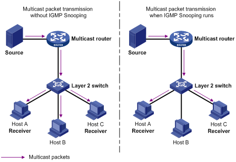
Figure 1-1 Comparison of multicast transmission before and after IGMP Snooping is enabled
1.1.2 IGMPv3 Snooping
I. IGMPv3 overview
In addition to compatibility with and inheritance from IGMPv1 and IGMPv2, IGMPv3 provides an enhanced host control capability. A host can not only join a designated multicast group but also specify to receive information from a designated multicast source.
& Note:
S9500 series switches support IGMPv1 and IGMPv2, but they do not support IGMPv3 currently.
IGMP queries fall into general queries and group-specific queries. This section mainly introduces IGMPv3 messages that are different from in IGMPv2.
The following figure shows the differences between IGMPv2 and IGMPv3 query messages:
l The size of an IGMPv2 general query is eight bytes and that of an IGMPv3 general query is twelve bytes.
l The size of an IGMPv2 group-specific query is eight bytes and that of an IGMPv3 general query is equal to or greater than twelve bytes.
l The size of an IGMPv3 source-and-group-specific query is greater than twelve bytes.
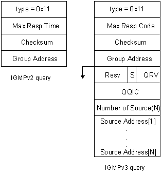
Figure 1-2 Message formats of IGMPv2 and IGMPv3 queries
The following figure shows the differences between IGMPv2 and IGMPv3 membership report messages:
l The type field of an IGMPv2 membership report is set to 0x16.
l IGMPv2 cannot recognize IGMPv3 membership report messages.
l Upon receiving an IGMPv3 report, the device transmits the IGMPv3 query transparently in the VLAN and converts it into an IGMPv2 report for further processing.
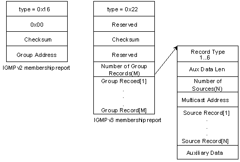
Figure 1-3 Message formats of IGMPv2 and IGMPv3 membership reports
II. Message processing in IGMPv3 Snooping on an S9500 switch
& Note:
Currently, the device supports only the INCLUDE mode of source filtering in IGMPv3 reports, that is, IGMPv3 report messages are converted to IGMPv2 reports except those with the filtering mode set to include { NULL }, which are converted to IGMPv2 leave messages.
With IGMPv3 Snooping enabled, upon receiving an IGMPv3 query, the device transmits the IGMPv3 query transparently in the VLAN and then converts it into an IGMPv2 report for further processing.
1.1.3 Implementing IGMP
Snooping
I. Concepts related to IGMP Snooping
To facilitate the description, this section first introduces some concepts related to IGMP Snooping.
l
l Multicast member port: The Ethernet switch port connected to a multicast member. The multicast member refers to a host joined a multicast group.
l MAC multicast group: The multicast group is identified by MAC multicast address and maintained by the Ethernet switch.
l Router port aging time: Time set on the router port aging timer. If the switch has not received any IGMP general query message when the timer expires, it considers the port no longer as a router port.
l Multicast group member port aging time: When a port joins an IP multicast group, the aging timer of the port is started. The multicast group member port aging time is set on this aging timer. If no IGMP report or PIM hello message reaches the port when the timer expires the switch sends a multicast group-specific query message. When the maximum response time expires, if no IGMP report reaches the port, the switch judges that the port is no longer a member port.
l Maximum response time: When the switch transmits IGMP group-specific query message to the multicast member port, the Ethernet switch starts a response timer. The maximum response time refers to the timer length. If the switch has not received any IGMP report message before the timer expires, it will remove the port from the multicast member ports.
II. Implementing Layer 2 multicast with IGMP Snooping
1) IGMP general query message: Transmitted by the multicast router to the multicast group members to query which multicast group contains a member. When an IGMP general query message arrives at the router port, the Ethernet switch will reset the aging timer of the port. When a port other than the router port receives the IGMP general query message, the Ethernet switch will start the aging timer for the port.
2) IGMP group-specific query message: IGMP group-specific query messages are used to find out whether a particular group still has members on the local subnet. Upon hearing an IGMP group-specific query message, the switch sends the group-specific query message only to the multicast group being queried.
3) IGMP report message: IGMP report messages are sent by hosts to the multicast router to join multicast groups or report their group memberships in response to IGMP query messages. Upon hearing an IGMP report message, the switch checks whether the MAC multicast group corresponding to the reported IP multicast group exists and proceeds accordingly.
l If the MAC multicast group does not exist, the switch notifies the router that a member is ready to join the reported multicast group, creates a new MAC-based forwarding entry, adds the port that received the report message to the entry, starts an aging timer for the port, and then adds all the router ports in the native VLAN of the port into the MAC multicast forwarding table.
l If the corresponding MAC multicast group exists but does not contain the port received the report message, the switch adds the port into the multicast group and starts the port aging timer.
l If the MAC multicast group exists and contains the port that received the message, the switch will only reset the aging timer of the port.
4) IGMP leave message: Transmitted from the multicast group member to the multicast router to notify that a host left the multicast group. Upon hearing a leave message for an IP multicast group, the Ethernet switch sends a group-specific query message for that group to the port on which it heard the message, to check whether any other active members for that group are attached to the port, and meanwhile starts a maximum response timer. If the switch receives no report message for that multicast group before the timer expires, the port will be removed from the corresponding MAC-based forwarding table entry. If the switch has no more member ports for that MAC multicast group, the switch will notify the upstream multicast router to prune the branch off the multicast distribution tree.
& Note:
l You can configure a port of a Layer 2 switch as a multicast group member to respond to an IGMP query message of a multicast router, so as to prevent the multicast router from canceling the corresponding path if there is no multicast member in the current network segment. For details, refer to IGMP Configuration in the IP Multicast Volume.
l By default, ports of a Layer 2 switch do not belong to any multicast group. Note that, the specified port must belong to an IGMP Snooping-enabled VLAN. Otherwise, the configuration will not work.
1.2 IGMP Snooping Configuration Tasks
l Configuring IGMP Snooping Parameters
l Disabling Flooding of Unknown Multicast Packets in the VLAN
l Configuring an ACL for Filtering Multicast Groups
l Configuring the Fast Leave Function
l Configuring the Host Port Function
l Static Router Port Configuration
l Configuring IGMP Snooping Multicast Data Load Balancing
l Configuring an IGMP Snooping Querier
l Configuring IGMP Report Replay Suppression
l Configuring IGMP Leave Relay Suppression
l Multicast Forwarding on Demand
1.2.1 Enabling IGMP
Snooping
You can control the creation and maintenance of MAC multicast tables at Layer 2 by enabling IGMP Snooping.
I. Configuration prerequisites
l Make sure Layer 2 and Layer 3 multicast protocols are not enabled in the same VLAN or on the same VLAN interface.
l VLAN VPN is disabled in the VLAN.
II. Configuration procedure
Follow these steps to enable IGMP Snooping:
|
To do... |
Use the command... |
Remarks |
|
Enter system view |
system-view |
— |
|
Enable IGMP Snooping |
igmp-snooping { enable | disable } |
Required IGMP Snooping is disabled by default. |
|
Enter VLAN view |
vlan vlan-id |
— |
|
Enable IGMP Snooping |
igmp-snooping { enable | disable } |
Required IGMP Snooping is disabled by default. |
|
Display IGMP Snooping configuration |
display igmp-snooping configuration |
The display command can be executed in any view. |
![]() Caution:
Caution:
l Before configuring IGMP Snooping, first enable it globally in system view and then enable it in VLAN view. Otherwise, the configuration will not work.
l IGMP Snooping is applicable to isolate-user VLANs. If IGMP Snooping is enabled in an isolate-user VLAN, it is enabled in all the secondary VLANs. Therefore, enabling IGMP Snooping in a secondary VLAN is not necessary.
l The IGMP packets in a secondary VLAN are processed in the isolate-user VLAN. That is, for a user-isolate VLAN, all the multicast services are processed in the isolate-user VLAN.
l A port in a secondary VLAN cannot be used for receiving multicast traffic.
1.2.2 Configuring IGMP
Snooping Parameters
IGMP Snooping parameters include:
l Router port aging time
l Maximum response time
l Multicast group member port aging time
I. Configuration prerequisites
IGMP Snooping is enabled globally.
II. Configuration procedure
Perform the following operations to configure IGMP Snooping parameters:
|
To do... |
Use the command... |
Remarks |
|
Enter system view |
system-view |
— |
|
Configure router port aging time |
igmp-snooping router-aging-time seconds |
Optional By default, the route port aging time is 260 seconds |
|
Configure maximum response time |
igmp-snooping max-response-time seconds |
Optional By default the maximum response time is 1 second |
|
Configure multicast group member port aging time |
igmp-snooping host-aging-time seconds |
Optional By default, the multicast group member port aging time is 260 seconds. |
1.2.3 Disabling Flooding
of Unknown Multicast Packets in the VLAN
If neither IGMP Snooping nor Layer 3 multicast is enabled in a VLAN, unknown multicast packets are flooded in the VLAN. Therefore, to disable unknown multicast packets from being flooded in a VLAN, you need to enable IGMP Snooping in the VLAN and execute the igmp-snooping nonflooding-enable command.
I. Configuration prerequisites
IGMP Snooping is enabled in the VLAN.
II. Configuration procedure
Follow these steps to disable flooding of unknown multicast packets in the VLAN on a general board:
|
To do... |
Use the command... |
Remarks |
|
Enter system view |
system-view |
— |
|
Disable flooding of unknown multicast packets in the VLAN |
igmp-snooping nonflooding-enable |
By default, multicast packets are flooded in a VLAN. |
1.2.4 Configuring an ACL
for Filtering Multicast Groups
I. Configuration prerequisites
IGMP Snooping is enabled globally.
II. Configuration procedure
Follow these steps to configure an ACL for filtering multicast groups:
|
To do... |
Use the command... |
Remarks |
|
Enter system view |
system-view |
— |
|
Enter VLAN view |
vlan vlan-id |
— |
|
Apply an ACL for filtering multicast groups in the VLAN |
igmp-snooping group-policy acl-number |
Required By default, the ACL for filtering multicast groups is not configured in a VLAN. In this case, a host can join any multicast group. After the ACL for filtering multicast groups is configured, the multicast groups that are not permitted by the ACL cannot be created. |
![]() Caution:
Caution:
l If the ACL applied to a VLAN does not exist or contain any rule, the host cannot join any multicast group.
l The rules of the ACL for filtering multicast groups are not limited by the ACL. This function applies to all the members in the specified VLAN.
l The rules for filtering multicast groups take effect only when the configuration policy bound to the ACL number exists.
l The rules for filtering multicast groups have no effect on locally configured static multicast groups.
1.2.5 Configuring the Fast
Leave Function
I. Configuration prerequisites
IGMP Snooping is enabled globally.
II. Configuration procedure
Follow these steps to configure the fast leave function:
|
To do... |
Use the command... |
Remarks |
|
Enter system view |
system-view |
— |
|
Enable the fast leave function |
igmp-snooping fast-leave [ vlan { vlan-id [ to vlan-id ] } &<1-10> ] |
This function is disabled by default. |
|
Enter Ethernet port view |
interface interface-type interface-number |
— |
|
Enable the fast leave function |
igmp-snooping fast-leave [ vlan { vlan-id [ to vlan-id ] } &<1-10> ] |
This function is disabled by default |
& Note:
The fast leave configuration performed in system view and that performed in port view are independent of each other. That is, the configuration performed in system view is effective to all the ports in the specified VLAN, whereas the configuration performed in port view is effective for the port in the specified VLAN. For example, a trunk port belongs to multiple VLANs.
![]() Caution:
Caution:
l The fast leave function cannot take effect if the specified VLAN does not exist, the port does not belong to the specified VLAN, or IGMP Snooping is not enabled in the VLAN.
l If you enable IGMP Snooping again, the original configuration of fast leave will be cleared.
l You cannot configure this command when IGMP Snooping is not enabled globally. (You can use the igmp-snooping enable command in system view to enable IGMP Snooping globally.)
l For an aggregation port, the fast leave function only takes effects on the master aggregation port.
l If an IGMPv1 host in the same group joins the port, even if fast leave is enabled on the port, it does not take effect.
1.2.6 Configuring the
Host Port Function
In a healthy multicast network, devices receive IGMP queries and PIM hello packets only on their router ports. However, in actual applications, devices may be attacked by malicious packets received on normal ports (such as malicious IGMP queries), and as a result, a device takes a normal port as a router port by mistake.
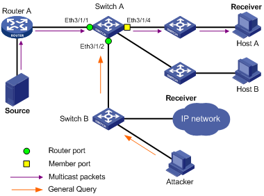
Figure 1-4 Network diagram for host-port configuration
As shown in Figure
1-4, upon receiving malicious IGMP query messages sent by the attacker,
Switch A identifies Ethernet
In complicated networks like a ring network at the user end, the host-port function can be enabled to avoid loop-forwarding of IGMP query messages.
Follow these steps to configure the host port function:
|
To do... |
Use the command... |
Remarks |
|
Enter system view |
system-view |
— |
|
Enter Ethernet port view |
interface interface-type interface-number |
— |
|
Enable the host port function |
igmp-snooping host-port vlan { all | vlan-id } |
Required This function is disabled by default. |
& Note:
Do not enable the host port function on a router port.
1.2.7 Static Router Port
Configuration
By configuring a port in a VLAN to be a static router port, you can enable IGMP packets to be transparently transmitted through the port, meeting the requirements of specific networks.
I. Configuration prerequisites
l The port and VLAN involved already exist.
l The port to be configured belong to the corresponding VLAN.
II. Configuring a static router port
Follow these steps to configure a port in a VLAN to be a static router port in VLAN view:
|
To do... |
Use the command... |
Remarks |
|
Enter system view |
system-view |
— |
|
Enter VLAN view |
vlan vlan-id |
— |
|
Configure a static router port |
multicast static-router-port port-number |
The port-number argument is in the format of interface-type interface-number, where the interface-type argument can only be Ethernet port type. By default, no static router port is configured. |
Follow these steps to configure a port in a VLAN to be a static router port in Ethernet port view:
|
To do... |
Use the command... |
Remarks |
|
Enter system view |
system-view |
— |
|
Enter Ethernet port view |
interface interface-type interface-number |
The interface-type argument can only be Ethernet port type. |
|
Configure a static router port |
multicast static-router-port vlan vlan-id |
By default, no static router port is configured. |
![]() Caution:
Caution:
l You will fail to configure a port to be a static router port if the port identified by the port-number argument does not exist, or the port does not belong to the VLAN.
l You will fail to configure a port to be a static router port if the VLAN identified by the vlan-id argument does not exist or the port does not belong to the VLAN.
l You can configure multiple ports in a VLAN to be static router ports by performing the above configuration repeatedly. The newly configured ports do not overwrite the existing static router ports.
l When a trunk port belongs to multiple VLANs, this port can be configured as the static router port for multiple VLANs.
l Static router ports can be configured in VLAN view or Ethernet port view. However, you can verify the configured static router ports only by executing the display this command in Ethernet port view.
l The configuration of a static router port takes effect on the current port only, no matter whether the current port is an aggregated port or not. To configure all ports in an aggregation group as static router ports, you can enable the static router port function on all the ports in the aggregation group.
l The static router port is valid when IGMP Snooping, IGMP, PIM-DM or PIM-SM is enabled in the VLAN.
1.2.8 Configuring IGMP
Snooping Multicast Data Load Balancing
After IGMP Snooping is enabled in a VLAN, multicast packets will be flooded in the VLAN if no port has joined the destination multicast group. With IGMP Snooping non-flooding enabled, data packets are not flooded in the VLAN but are forwarded to router ports if no member port for the destination multicast group exists. Since multicast routers send IGMP query and PIM Hello messages periodically, the switch can recognize which ports are router ports. If neither member ports nor router ports exist, multicast packets are dropped.
When a user joins a multicast group, the device deletes the original multicast MAC address created by IGMP-snooping non-flooding and creates a new IGMP-snooping multicast MAC address. With the IGMP Snooping non-flooding function enabled, if any router port is in an aggregation group, the system can evenly distribute unknown multicast traffic to different aggregation ports according to the hash algorithm, thus implementing load balancing of multicast traffic.
Follow these steps to configure IGMP Snooping multicast non-flooding:
|
To do... |
Use the command... |
Remarks |
|
Enter system view |
system-view |
— |
|
Enable IGMP Snooping |
igmp-snooping enable |
Required |
|
Enable IGMP Snooping non-flooding |
igmp-snooping nonflooding-enable |
Required |
|
Configure aging time point for IGMP Snooping non-flooding entries |
igmp-snooping non-flooding entry-age-time hh:mm:ss |
Optional By default, the aging time is 3:00:00 |
|
Display the configuration information |
display igmp-snooping configuration |
The display command can be executed in any view |
![]() Caution:
Caution:
l When you enable IGMP Snooping non-flooding, a aging time point is configured. The default aging time point is 3:00:00.
l After you disable IGMP Snooping or IGMP Snooping non-flooding, the aging time point is invalidated at the same time.
1.2.9 Configuring an IGMP Snooping Querier
IGMP Snooping runs on Layer 2 switches connecting with users and layer-3 devices. Layer-3 devices send general queries to maintain membership in the local subnet. The IGMP Snooping–enabled device maintains Layer 2 multicast forwarding tables by listening to IGMP messages. Where Layer 2 multicast is implemented without the need of Layer-3 devices, IGMP Snooping queriers can establish and maintain multicast forwarding tables.
IGMP Snooping queriers are used in Layer 2–only multicast networks.
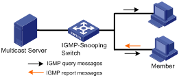
Figure 1-5 Implement IGMP Snooping query
IGMP Snooping querier configuration tasks include:
l Enabling IGMP Snooping
l Configuring the interval at which the IGMP Snooping querier sends general queries in a VLAN
l Configuring a maximum response time of IGMP general queries in a VLAN
l Configuring the source IP address the IGMP Snooping querier uses to send general query messages in a VLAN
l Configuring an IGMP Snooping querier
I. Configuration prerequisites
l Layer 2 and Layer 3 multicast protocols cannot be enabled in the same VLAN or on the same VLAN interface.
l VLAN VPN is disabled in the VLAN.
l VLAN VPN-enabled ports are not added into this VLAN.
II. Configuration procedure
Follow these steps to configure an IGMP Snooping querier:
|
To do... |
Use the command... |
Remarks |
|
Enter system view |
system-view |
— |
|
Enable IGMP Snooping |
igmp-snooping { enable | disable } |
Required This function is disabled by default. |
|
Enter VLAN view |
vlan vlan-id |
— |
|
Enable IGMP Snooping |
igmp-snooping { enable | disable } |
Required This function is disabled by default. |
|
Configure the interval at which the IGMP Snooping querier sends general queries in the VLAN |
igmp-snooping query-interval time-interval |
Optional By default, the query interval is 60 seconds. |
|
Configure a maximum response time |
igmp-snooping max-response-time max-response-time |
Optional By default, the maximum response time of an IGMP query message is 10 seconds. |
|
Configure a source IP address of general query messages |
igmp-snooping general-query source-ip { current-interface | ip-address } |
Optional By default, the source IP address is |
|
Enable IGMP Snooping querier |
igmp-snooping querier |
Required By default, IGMP Snooping querier is not enabled in a VLAN. |
|
Display the IGMP Snooping configuration information in a VLAN |
display igmp-snooping configuration vlan vlan-id |
The display command can be executed in any view. |
& Note:
l
The default source IP address of IGMP general queries
is
l If you need to configure multiple queriers, it is advisable that you configure a longer query interval to prevent deterioration of device performance caused by too many IGMP general queries.
1.2.10 Configuring IGMP
Report Replay Suppression
If IGMP Snooping relays (namely, forwards without any change) every IGMP report message it hears on a port in an IGMP Snooping–enabled VLAN immediately to router ports in the VLAN, the upstream device may suffer from a big burden. Therefore, IGMP report relay needs to be suppressed in an IGMP Snooping–enabled VLAN.
With the IGMP report relay suppression function enabled, within each query cycle, the Layer 2 device relays only the first IGMP report per multicast group to the Layer 3 device and will not relay the subsequent IGMP reports for the same multicast group to the Layer 3 device. This helps reduce the traffic over the network.
& Note:
l Currently, S9500 series switches do not support suppression of IGMPv3 report messages.
l The IGMP report relay suppression feature is effective only for a VLAN with IGMP Snooping enabled.
Follow these steps to enable IGMP report relay suppression:
|
To do... |
Use the command... |
Remarks |
|
Enter system view |
system-view |
— |
|
Enable IGMP Snooping |
igmp-snooping enable |
Required |
|
Enable IGMP report relay suppression |
igmp-snooping report-aggregation |
Required By default, this function is disabled. |
|
Display the IGMP Snooping configuration information in system view |
display igmp-snooping configuration |
The display command can be executed in any view. |
1.2.11 Configuring IGMP
Leave Relay Suppression
If IGMP Snooping relays (namely, forwards without any change) every IGMP leave message it hears on a port in an IGMP Snooping–enabled VLAN immediately to router ports in the VLAN, the upstream device may suffer from a big burden. In networks where Layer 2 multicast devices are cascaded or connected in a ring, IGMP leave relay may cause mutual influence between multicast streams on different devices.
To address this problem, the S9500 series switches provide an IGMP leave relay suppression mechanism. In a cascaded or ring network, IGMP leave messages are suppressed in IGMP Snooping–enabled VLANs to eliminate influence on multicast streams between multicast sub-VLANs on the same device or between different devices.
With the IGMP leave relay suppression function enabled, the Layer 2 device will not relay the leave messages it hears to the Layer 3. Instead, the device generates an IGMP leave message and sends it to the upstream device after the last member in the VLAN has left the multicast group indicated in the IGMP leave messages it received.
Follow these steps to enable IGMP leave relay suppression:
|
To do... |
Use the command... |
Remarks |
|
Enter system view |
system-view |
— |
|
Enable IGMP Snooping |
igmp-snooping enable |
Required |
|
Enable IGMP leave relay suppression |
igmp-snooping leave-aggregation |
Required By default, this function is disabled. |
|
Display the IGMP Snooping configuration information in system view |
display igmp-snooping configuration |
The display command can be executed in any view. |
& Note:
l Currently, S9500 series switches do not support suppression of IGMPv3 leave messages.
l The IGMP leave relay suppression feature is effective only for a VLAN with IGMP Snooping enabled.
l With the IGMP leave relay suppression feature enabled, the upstream Layer 3 multicast device will be unable to obtain the real information (such as source IP address) of hosts leaving multicast groups.
l In all situations involving multicast group removal except when a leave message is received or when a member port is normally aged, for example when the multicast protocol is disabled or the port connecting the last multicast group member goes down, the Layer 2 device immediately generates a leave message and sends it to the upstream multicast device.
l If no IP address is configured for the VLAN interface corresponding to the VLAN involving a multicast group removal operation, the device generates a leave message with an all-zero source IP address. This may cause the upstream device to process the leave message incorrectly. Therefore, it is recommended that you configure a non-all-zero IP address for VLAN interfaces.
l When many multicast groups are removed instantaneously, the Layer 2 device may fail to send leave messages it has constructed for some multicast groups due to limitation of its packet handling capability. In this case, the upstream Layer 3 device will delay removing the multicast groups and continue forwarding multicast traffic downstream, which will be directly dropped by the downstream device as unknown multicast traffic. Such unwanted multicast traffic will waste the network bandwidth. On the other hand, even if all the leave messages constructed by the Layer 2 device are successful sent out, the Layer 3 device may fail to receive all of them due to limitation of its packet handling capability or poor link conditions. This will also result in unwanted multicast traffic forwarded down by the upstream Layer 3 device, causing waste of network resources.
1.2.12 Multicast Forwarding
on Demand
I. Overview
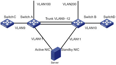
Figure 1-6 Network diagram for multicast forwarding on demand
As shown in Figure 1-6, Switch A and Switch B are connected through a trunk link, which allows packets of VLAN 9 through VLAN 12 to pass. The server connects to Switch A and Switch B separately through two NIC cards working in the active/standby mode.
Switch A and Switch B are configured to be PIM neighbors for each other in VLAN 9.
Upon receiving a multicast stream from Switch C, Switch A forwards the data stream through the router port in VLAN 9 to Switch B. Switch B discards the multicast stream because no outbound interface exists on it in VLAN 9.
On the other hand, Switch A transfers the multicast stream from VLAN 9 to VLAN 11 by means of Layer 3 multicasting to the server. The server then delivers the data stream to Switch B. Upon receiving the data stream, Switch B performs RPF check and floods the stream in VLAN 11 because the RPF check fails. As a result, the server receives the multicast stream on the secondary NIC. If a great number of such data streams are received on the standby NIC, the server fails to implement active/standby switchover normally. To avoid this issue, you need to configure the multicast forwarding on demand function on Switch B in VLAN 11. This function prevents multicast streams that fail the RPF check from being flooded in a VLAN.
II. Configuration prerequisites
IGMP Snooping is globally configured.
III. Configuration procedure
Follow these steps to configure the multicast-on-demand function
|
To do... |
Use the command... |
Remarks |
|
Enter system view |
system-view |
— |
|
Enable IGMP snooping |
igmp-snooping enable |
Required This function is disabled by default. |
|
Enable the IGMP snooping non-flooding function |
igmp-snooping nonflooding-enable |
Required Unknown multicast packets are flooded in a VLAN by default. |
|
Configure the interval at which the IGMP Snooping querier sends general queries in a VLAN |
igmp-snooping query-interval time-interval |
Optional By default, the query interval is 60 seconds. |
|
Enter VLAN view |
vlan vlan-id |
— |
|
Enable the multicast-on-demand function |
multicast forward according-to-need |
Required Disabled by default. |
& Note:
You need to clear all IGMP and Layer 3 multicast group table entries using the reset command to bring this configuration into effect.
1.3 Displaying and Maintaining IGMP Snooping
|
To do... |
Use the command... |
Remarks |
|
Display the information about current IGMP Snooping configuration |
display igmp-snooping configuration |
Available in any view |
|
Display IGMP Snooping statistics of received and sent messages |
display igmp-snooping statistics |
|
|
Display IP/MAC multicast group information in a VLAN |
display igmp-snooping group [ vlan vlan-id [group-address] ] |
|
|
Enable IGMP Snooping debugging |
debugging igmp-snooping { abnormal | all | events | forward | groups | packets | timers } |
|
|
Clear IGMP Snooping statistics information |
reset igmp-snooping statistics |
Available in user view |
1.4 IGMP Snooping Configuration Example
I. Network requirements
l As shown in Figure
1-7, Router A connects to the multicast source (Source in the
figure) through Ethernet
l IGMPv2 is required between Router A and Switch A, IGMP Snooping is required on Switch A, and PIM-DM is required on Router A.
l Receivers of specified multicast groups are attached to Ethernet
l It is required to configure IGMP Snooping so that multicast traffic will be forwarded only to member ports but not broadcast in the VLAN.
II. Network diagram
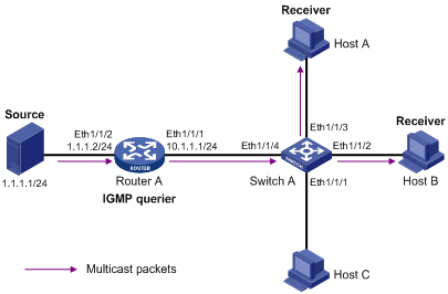
Figure 1-7 Network diagram for IGMP Snooping configuration
III. Configuration procedure
1) Configure IP addresses
Configure an IP address and subnet mask for each interface as per Figure 1-7. The detailed configuration steps are omitted here.
2) Configure Router A
# Enable IP multicast routing, enable
PIM-DM on each interface, and enable IGMPv2 on Ethernet
<RouterA> system-view
[RouterA] multicast routing-enable
[RouterA] interface ethernet
[RouterA-Ethernet
[RouterA-Ethernet
[RouterA-Ethernet
[RouterA-Ethernet
[RouterA] interface ethernet
[RouterA-Ethernet
[RouterA-Ethernet
& Note:
The configuration on Router A given above is for reference only and may differ from the actual configuration on your devices.
3) Configure Switch A
# Create VLAN 100.
<SwitchA> system-view
[SwitchA] vlan 100
# Assign Ethernet
[SwitchA-vlan100] port ethernet
[SwitchA-vlan100] quit
# Enable IGMP Snooping in VLAN 100.
[SwitchA] igmp-snooping
[SwitchA-igmp-snooping] quit
[SwitchA] vlan 100
[SwitchA-vlan100] igmp-snooping enable
[SwitchA-vlan100] quit
1.5 Troubleshooting IGMP Snooping
Symptom: The multicast function cannot be implemented on the switch.
Analysis and solutions:
1) IGMP Snooping is disabled.
l Carry out the display current-configuration command in any view to display the status of IGMP Snooping.
l If IGMP Snooping is not enabled, carry out the igmp-snooping enable command in system view to enable IGMP Snooping. Then, use the same command in VLAN view to enable IGMP Snooping in the corresponding VLAN.
2) Multicast forwarding table set up by IGMP Snooping is incorrect.
l Carry out the display igmp-snooping group command in any view to display if the multicast group is the expected one.
l If the multicast group created by IGMP Snooping is not correct, contact maintenance personnel for help.
l Continue with diagnosis 3 if the second step is completed.
3) Multicast forwarding table set up at the bottom layer is incorrect.
l In any view, carry out the display mac-address vlan command to check whether the MAC multicast forwarding table established at the bottom layer by vlan-id is consistent with that established by IGMP Snooping.
l If they are not consistent, contact the maintenance personnel for help.