- Table of Contents
- Related Documents
-
| Title | Size | Download |
|---|---|---|
| 01-Multicast Overview | 205.12 KB |
1.1.1 Comparison of Three Information Transmission Technologies
1.1.2 Application of Multicast
1.2 Implementation of IP Multicast
1.3 RPF Mechanism for IP Multicast Packets
Chapter 1 Multicast Overview
An Ethernet switch functions as a router when it runs IP multicast protocol. The term “router” in this document refers to a router in a generic sense or a Layer 3 Ethernet switch that running the IP multicast protocol.
1.1 IP Multicast Overview
Compared with unicast and broadcast, multicast effectively addresses the issue of point-to-multipoint data transmission. By allowing high-efficiency point-to-multipoint data transmission, multicast greatly saves network bandwidth and reduces network load.
With the multicast technology, a service provider can easily provide new value-added services, such as live Webcasting, Web TV, Tele-education, Tele-medicine, Web radio, online videoconferencing, and other bandwidth- and time-sensitive information services.
1.1.1 Comparison of Three Information Transmission Technologies
With the development of the Internet, more and more data, voice, and video information services are running on the Internet. In addition, bandwidth and time sensitive data services, such as e-business, Web conferencing, Web auction, video on demand, and distance learning, have ever higher security and privacy requirements.
I. Unicast
In unicast mode, the sender has to send a separate copy of information to each user. See Figure 1-1.
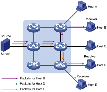
Figure 1-1 Data transmission in unicast mode
Suppose that Host B, Host D and Host E need the information, the information source (Server in the figure) establishes a separate transmission channel for each of them. Since the traffic in unicast transmission increases with the number of users, excessive copies of the information would spread over the network if there are a large number of users in need of this information. This means a tremendous pressure on the information source and the network bandwidth.
As we can see from the information transmission process, unicast is not suitable for batch transmission of information.
II. Broadcast
In broadcast mode, every user on the network receives the information regardless of their needs. See Figure 1-2.
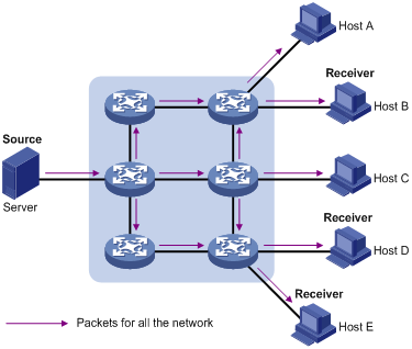
Figure 1-2 Data transmission in broadcast mode
Suppose Host B, Host D and Host E need the information and the information source Server broadcasts the information through the router. User A and User C can also receive the information. In addition to information security issues, this also causes traffic flooding on the same subnet.
Therefore, broadcast is disadvantageous in transmitting data to specific hosts; moreover, broadcast transmission is a significant waste of network resources.
In short, the unicast mode is useful in networks with scattered users, and the broadcast mode is suitable for networks with dense users. When the number of users is uncertain, the adoption of unicast or broadcast mode results in low efficiency.
III. Multicast
IP multicast technology solves those problems. When some users on the network need the information, the multicast information sender (namely, the multicast source) sends only one copy of the information. With a distribution tree established through a multicast routing protocol, multicast packets are duplicated and distributed only where the tree branches. See Figure 1-3.
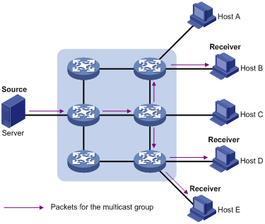
Figure 1-3 Data transmission in multicast mode
Assume that Host B, Host D and Host E need the information. To receive the information, these users need to join a receiver group. The multicast source sends only one copy of the information to the multicast group. The routers on the network duplicate and forward the information based on the distribution of the group members. Finally, the information is correctly delivered to Host B, Host D and Host E.
In multicast mode, an information sender is called a multicast source, a receiver group is called a multicast group, and the routers that deliver the multicast information are called multicast routers. Members of a multicast group can scatter around the Internet without any geographical restrictions. It should be noted that a multicast source does not necessarily belong to a multicast group. Multiple sources can send multicast streams to the same multicast group simultaneously.
IV. Advantages of multicast
The main advantages of multicast are:
l Enhanced efficiency: It reduces network traffic and relieves the server and CPU of loads.
l Optimized performance: It eliminates traffic redundancy.
l Distributed application: It allows point-to-multipoint application.
1.1.2 Application of Multicast
IP multicast technology effectively implements point to multi-point forwarding with high speed, as saves network bandwidth a lot and can relieve network loads. It also facilitates the development of new value-added services in the Internet information service area, such as online live show, Web TV, tele-education, telemedicine, network radio station and real-time audio/video conferencing. Multicast applications mainly include:
l Multimedia and streaming media application
l Occasional communication for training and cooperation
l Data storage and finance (stock) operation
l Point-to-multipoint data distribution
With the increasing popularity of multimedia services over IP network, multicast is gaining its marketplace. In addition, the multicast service becomes popular and prevalent gradually.
1.2 Implementation of IP Multicast
1.2.1 IP Multicast Addresses
In multicast mode, there are questions about where to send the information, how to locate the destination or know the receiver. All these questions can be narrowed down to multicast addressing. To guarantee the communication between a multicast source and a multicast group, a network layer multicast address (namely an IP multicast address is required for the group, and a technique is needed to map the IP multicast address to a MAC multicast address. Following is the introduction to these two kinds of multicast addresses.
I. IP Multicast addresses
According to the definition by Internet Assigned Number Authority (IANA), IP addresses fall into five classes: Class A, Class B, Class C, Class D, and Class E. Unicast packets use IP addresses of Class A, Class B, and Class C addresses. Destination addresses of multicast packets use IP addresses of Class D. A Class D address must not appear in the source address field of IP packets, while all Class E addresses are reserved for future use..
During unicast data transmission, a packet is routed "hop-by-hop" from the source address to the destination address. However, in IP multicast environment, the destination address of a packet is not a unicast IP address but a multicast address that identifies a group of users. All the receivers that need this information need to join the group.
Group memberships are dynamic. A host can join or leave a group at any time. A multicast group can be permanent or temporary. Some multicast group addresses are allocated by IANA, called permanent multicast group. The IP address of a permanent multicast group is unchangeable, but its memberships are changeable, and the number of members is not fixed. Addresses not reserved for permanent multicast groups can be used by temporary multicast groups. Class D multicast addresses range from 224.0.0.0 to 239.255.255.255. More information is listed in Table 1-1.
Table 1-1 Ranges and meanings of Class D addresses
Reserved multicast addresses that are commonly used are described in the following table.
Table 1-2 Reserved multicast addresses
|
Address range |
Description |
|
224.0.0.1 |
All systems in the local subnet, including hosts and routers |
|
224.0.0.2 |
All multicast routers in the local subnet |
|
224.0.0.3 |
Unassigned |
|
224.0.0.4 |
DVMRP routers |
|
224.0.0.5 |
OSPF routers |
|
224.0.0.6 |
OSPF DRs/backup OSPF DRs |
|
224.0.0.7 |
ST routers |
|
224.0.0.8 |
ST hosts |
|
224.0.0.9 |
RIP-2 routers |
|
224.0.0.11 |
Mobile agents |
|
224.0.0.12 |
DHCP server/Relay agent |
|
224.0.0.13 |
All PIM routers |
|
224.0.0.14 |
RSVP encapsulation |
|
224.0.0.15 |
All CBT routers |
|
224.0.0.16 |
Specified SBM |
|
224.0.0.17 |
All SBMS |
|
224.0.0.18 |
VRRP |
|
…… |
…… |
II. Ethernet multicast MAC addresses
When a unicast IP packet is transmitted on an Ethernet, the destination MAC address is the MAC address of the receiver. However, for a multicast packet, the destination is no longer a specific receiver but a group with unspecific members. Therefore, the multicast MAC address should be used.
As Internet Assigned Number Authority (IANA) provisions, the high 24 bits of a multicast MAC address are 0x01005e and the low 23 bits of a MAC address are the low 23 bits of a multicast IP address. The high twenty-fifth bit is 0, a fixed value.

Figure 1-4 Mapping between a multicast IP address and an Ethernet MAC address
The first four bits of the multicast address are 1110, representing the multicast identifier. Among the rest 28 bits, only 23 bits are mapped to the MAC address, and the other five bits are lost. This may results in that 32 IP multicast addresses are mapped to the same MAC address.
1.2.2 IP Multicast Protocols
Typically, the IP multicast protocols working at the network layer are called Layer 3 multicast protocols, including IGMP, PIM, MBGP, and MSDP; while the IP multicast protocols working at the data link layer are called Layer 2 multicast protocols, including IGMP Snooping and multicast VLAN.
I. Layer 3 multicast protocols
Layer 3 multicast protocols mainly include multicast group management protocols and multicast routing protocols. Figure 1-5 shows where they work in the network.
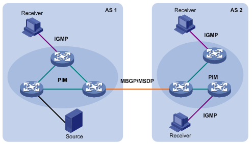
Figure 1-5 Positions of Layer 3 multicast protocols
1) Multicast group management protocols
Internet Group Management Protocol (IGMP) is the IPv4 multicast group management protocol, which runs between receiver hosts and routers directly connected with receivers. IGMP defines the membership establishment and maintenance mechanism between them.
2) Multicast routing protocols
A multicast routing protocol runs between Layer 3 multicast devices to create and maintain multicast routes for correct and efficient forwarding of multicast packet. The multicast routing creates a loop-free data transmission path from one source to multiple receivers, namely, a multicast distribution tree.
For the ASM model, multicast routing falls into intra-domain and inter-domain routing.
l Intra-domain multicast routing is to discover multicast sources in an autonomous system (AS), establish a multicast forwarding tree, and deliver multicast traffic through the forward tree to receivers. Among multiple inter-domain multicast routing protocols, Protocol Independent Multicast (PIM) is the most prevalent one. PIM delivers multicast data to receivers on the basis of source discovery and forwarding path establishment. Depending on the forwarding mechanisms, PIM can be further divided into PIM dense mode (PIM-DM) and PIM sparse mode (PIM-SM).
l Inter-domain multicast routing implements multicast transmission among ASs. Mature solutions include the Multicast Source Discovery Protocol (MSDP) and the Multicast Border Gateway Protocol (MBGP). MSDP is to communicate multicast source information among ASs, while MBGP is to propagate multicast routing information among ASs.
For the SSM model, multicast routes are not divided into inter-domain routes and intra-domain routes. Because receivers are aware of the position of the multicast source, dedicated multicast forwarding paths are established through PIM-SM for multicast transmission.
II. Layer 2 Multicast Protocols
Layer 2 multicast protocols include IGMP Snooping and multicast VLAN. Figure 1-6 shows where they work in the network.
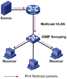
Figure 1-6 Positions of Layer 2 multicast protocols
1) IGMP Snooping
IGMP Snooping is a multicast constraining mechanism running on Layer 2 devices. By listening to and analyzing IGMP messages exchanged between hosts and Layer 3 multicast devices, IGMP Snooping manages and controls multicast groups, thus effectively suppressing flooding of multicast data in Layer 2 networks.
2) Multicast VLAN
In the traditional multicast-on-demand mode, when users in different VLANs on a Layer 2 device need multicast information, the upstream Layer 3 device needs to deliver a separate copy of the multicast data to each VLAN on the Layer 2 device. With the multicast VLAN feature enabled on the Layer 2 device, the Layer 3 device needs to send only one copy of multicast data to the multicast VLAN on the Layer 2 device. This avoids waste of network bandwidth and extra burden on the Layer 3 device.
1.3 RPF Mechanism for IP Multicast Packets