- Table of Contents
- Related Documents
-
| Title | Size | Download |
|---|---|---|
| 05-PIM Configuration | 263.88 KB |
Table of Contents
Chapter 1 PIM-DM Configuration
1.1.2 PIM-DM Working Principle
1.2.1 Enabling Multicast Routing
1.2.3 Configuring the Hello Interval
1.2.5 Configuring the Filtering of Multicast Source/Group
1.2.6 Configuring the Filtering of PIM Neighbors
1.2.7 Configuring the Maximum Number of PIM Neighbors on an Interface
1.2.8 Clearing PIM Routing Table Entries
1.3 Displaying and Debugging PIM-DM
1.4 PIM-DM Configuration Example
Chapter 2 PIM-SM Configuration
2.1.2 PIM-SM Working Principle
2.1.3 Configuration Prerequisites
2.2.1 Enabling Multicast Routing
2.2.4 Configuring the Hello Interval
2.2.5 Configuring Candidate-BSRs
2.2.6 Configuring Candidate-RPs
2.2.8 Configuring the PIM-SM Domain Border
2.2.9 Configuring the Filtering of Multicast Source/Group
2.2.10 Configuring the Filtering of PIM Neighbors
2.2.11 Configuring Filtering of the Register Messages from DRs
2.2.12 Configuring the Aging Time of PIM-SM Routing Entries
2.2.13 Limiting a Legal BSR Address Range
2.2.14 Limiting a Legal C-RP Range
2.2.15 Disabling RPT-to-SPT Switchover
2.2.16 Configuring SSM Mapping
2.2.17 Clearing Multicast Route Entries from PIM Routing Table
2.3 Displaying and Maintaining PIM-SM
2.4 PIM-SM Configuration Example
Chapter 1 PIM-DM Configuration
When configuring PIM-DM, go to the following sections for the information you are interested in:
l Displaying and Debugging PIM-DM
l PIM-DM Configuration Example
1.1 PIM-DM Overview
1.1.1 Introduction to PIM-DM
PIM-DM (Protocol Independent Multicast, Dense Mode) belongs to dense mode multicast routing protocols. PIM-DM is suitable for small networks. Members of multicast groups are relatively dense in such network environments.
1.1.2 PIM-DM Working Principle
PIM-DM involves three processes: neighbor discovery, flood & prune, and graft.
I. Neighbor discovery
The PIM-DM router needs to use Hello messages to perform neighbor discovery when it is started. All network nodes running PIM-DM keep in touch with one another with Hello messages, which are sent periodically.
II. Flood and prune
PIM-DM assumes that all hosts on the network are ready to receive multicast data. A multicast source "S" begins to send data to a multicast group "G". After the router receives the multicast packets, the router will perform RPF check according to the unicast routing table. If the RPF check is passed, the router will create an (S, G) entry and then flood the data to all downstream PIM-DM nodes. If the RPF check fails (that is, multicast packets enter from an error interface), the packets will be discarded. After this process, an (S, G) entry will be created in the PIM-DM multicast domain.
If the downstream node has no multicast group members, it will send a Prune message to the upstream node not to forward data to the downstream node. Receiving the prune message, the upstream node will remove the corresponding interface from the outgoing interface list corresponding to the multicast forwarding entry (S, G). In this way, a Shortest Path Tree (SPT) rooted at Source S is built. The pruning process is initiated by leaf routers first.
This process is called “flood & prune” process. In addition, nodes that are pruned provide timeout mechanism. Each router re-starts the “flood & prune” process upon pruning timeout. The “flood & prune” process of PIM-DM is performed periodically.
During this process, PIM-DM uses the RPF check and the existing unicast routing table to build a multicast forwarding tree rooted at the data source. When a packet arrives, the router will first judge the path for correctness. If the interface on which the packet arrived is the one indicated by the unicast routing to the multicast source, the packet is regarded to be from the correct path. Otherwise, the packet will be discarded as a redundancy packet without the multicast forwarding. The unicast routing information as path judgment can come from any unicast routing protocol such as the routing information learned by RIP and OSPF, instead of a specific unicast routing protocol.
III. Assert mechanism
On a subnet with multiple routers, duplicated multicast packets may be forwarded to the subnet. To avoid such cases, the assert mechanism is introduced to elect a unique multicast forwarder on a multi-access subnet.
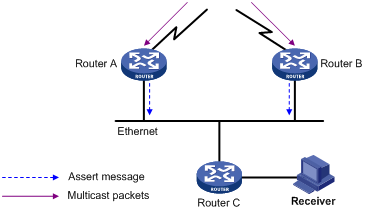
Figure 1-1 Assert mechanism diagram
As shown in Figure 1-1, Router A and Router B both forward a packet to the subnet upon receiving a (S, G) multicast packet from the upstream node. Router C receives two copies of the same multicast data. Router A and Router B also receive the multicast data on their local interfaces respectively. In this case, both Router A and Router B send an assert message to the all-PIM-router multicast group (224.0.0.13) through the interface on which the packet was received. An assert message carries the following information: multicast source address, multicast group address, and the preference and metric of the unicast route to the multicast source. After comparison of the parameters based on a certain algorithm, the winner in the election becomes the unique forwarder for (S, G) multicast traffic onto the subnet. The election process is as follows:
1) The router with a higher route preference to the source wins.
2) If both routers have the same unicast route preference to the source, the router with a smaller metric to the source wins.
3) If there is a tie in route metric to the source, the router with a higher IP address of the local interface wins.
& Note:
Currently the assert mechanism is not supported on H3C S9500 series routing switches.
IV. Graft
When the pruned downstream node needs to be restored to the forwarding state, the node will send a graft packet to inform the upstream node.
1.2 PIM-DM Configuration
1) Basic PIM-DM configuration includes:
2) Advanced PIM-DM configuration includes:
l Configuring the Hello Interval
l Configuring the Filtering of Multicast Source/Group
l Configuring the Filtering of PIM Neighbors
l Configuring the Maximum Number of PIM Neighbors on an Interface
l Clearing PIM Routing Table Entries
1.2.1 Enabling Multicast Routing
Refer to Common Multicast Configuration in the IP Multicast Volume.
1.2.2 Enabling PIM-DM
PIM-DM needs to be enabled on all interfaces.
After PIM-DM is enabled on an interface, it will send PIM Hello messages periodically and process protocol packets sent by PIM neighbors.
Perform the following operations in VLAN interface view to enable/disable PIM-DM:
|
To do... |
Use the command... |
|
Enable PIM-DM on an interface |
pim dm |
|
Disable PIM-DM on an interface |
undo pim dm |
It’s recommended to configure PIM-DM on all interfaces in non-special cases. This configuration is effective only after the multicast routing is enabled in system view.
Once PIM-DM is enabled on an interface, PIM-SM cannot be enabled on the same interface and vice versa.
1.2.3 Configuring the Hello Interval
When protocol independent multicast (PIM) protocol is enabled for a port, the port sends Hello packets periodically. The Hello interval varies with the bandwidth and type of the connected networks.
Perform the following operations in interface view to configure the Hello interval:
|
To do... |
Use the command... |
|
Configure the time intervals for ports to send Hello packets |
pim timer hello seconds |
|
Restore the default values of the time intervals |
undo pim timer hello |
By default, the Hello interval is 30 seconds. You can configure different Hello intervals according to the actual networks. In general, you need not modify the seconds argument.
& Note:
l The Hello interval can be configured only after the PIM protocol such as protocol independent multicast-dense mode (PIM-DM) or protocol independent multicast-sparse mode (PIM-SM) is enabled in interface view.
l When you configure the Hello interval, the PIM neighbor hold-time value automatically turns into 3.5 times the Hello interval. Therefore you need not configure a value for PIM neighbor hold-time.
1.2.4 Entering PIM View
Global parameters of PIM should be configured in PIM view.
Perform the following operations to enter PIM view or return to system view:
|
To do... |
Use the command... |
|
Enter PIM view |
pim |
|
Clear the configuration performed in PIM view and return to system view |
undo pim |
1.2.5 Configuring the Filtering of Multicast Source/Group
You can set to filter the source (and group) address of multicast data packets via this command. When this feature is configured, the router filters not only multicast data, but the multicast data encapsulated in the registration packets.
Perform the following operations in PIM view to configure/remove the filtering of multicast source/group:
|
To do... |
Use the command... |
|
Configure the filtering of multicast source/group |
source-policy acl-number |
|
Remove the configuration of filtering |
undo source-policy |
If source address filtering as well as a basic ACL is configured, then the router matches the source addresses of all multicast data packets received against the basic ACL. Those not matched will be discarded.
If source address filtering as well as an advanced ACL is configured, then the router matches the source and group addresses of all multicast data packets received against the advance ACL. Those not matched will be discarded.
This command also filters multicast data encapsulated in registration packets.
If this command is executed for a second time, the previous configuration will be overwritten by the new configuration.
1.2.6 Configuring the Filtering of PIM Neighbors
You can configure basic ACLs to filter the routers which can be PIM neighbors of the current interface.
Perform the following operations to configure/remove the filtering of PIM neighbors in interface view:
|
To do... |
Use the command... |
|
Configure filtering of PIM neighbor |
pim neighbor-policy acl-number |
|
Remove the configuration of filtering |
undo pim neighbor-policy |
1.2.7 Configuring the Maximum Number of PIM Neighbors on an Interface
The maximum number of PIM neighbors of a router interface can be configured to avoid exhausting the memory of the router or router faults. The maximum number of PIM neighbors of a router is defined by the system, and is not open for modification.
Perform the following operation in interface view to configure/restore the maximum number of PIM neighbors:
|
To do... |
Use the command... |
|
Configure the maximum number of PIM neighbor on an interface |
pim neighbor-limit limit |
|
Restore the limit of PIN neighbor to the default value |
pim neighbor-limit |
By default, the PIM neighbors on the interface are limited to 128.
If you configure PIM neighbors more than the configured value on an interface, the existing PIM neighbors will not be deleted.
1.2.8 Clearing PIM Routing Table Entries
Perform the following operation in user view to clear multicast route entries from PIM routing table:
|
To do... |
Use the command... |
|
Clear multicast route entries from PIM routing table |
reset pim routing-table { all | { group-address [ mask { group-mask | group-mask-length } ] | source-address [ mask { source-mask | source-mask-length } ] | { incoming-interface interface-type interface-number | null } } * } |
1.2.9 Clearing PIM Neighbors
Perform the following operation in user view to clear PIM neighbors:
|
To do... |
Use the command... |
|
Clear PIM neighbors |
reset pim neighbor { all | { neighbor-address | interface interface-type interface-number } * } |
1.3 Displaying and Debugging PIM-DM
|
To do... |
Use the command... |
Remarks |
|
Display the PIM multicast routing table |
display pim routing-table [ { { *g [ group-address [ mask { mask-length | mask } ] ] | **rp [ rp-address [ mask { mask-length | mask } ] ] } | { group-address [ mask { mask-length | mask } ] | source-address [ mask { mask-length | mask } ] } * } | incoming-interface interface-type interface-number | null } | { dense-mode | sparse-mode } ] * |
Available in any view |
|
Display the PIM interface information |
display pim interface [ Vlan-interface Vlan-interface-number ] |
Available in any view |
|
Display the information about PIM neighboring routers |
display pim neighbor [ interface Vlan-interface Vlan-interface-number ] |
Available in any view |
|
Display BSR information |
display pim bsr-info |
Available in any view |
|
Display RP information |
display pim rp-info [ group-address ] |
Available in any view |
|
Enable the PIM debugging |
debugging pim common { all | event | packet | timer } |
Available in user view |
|
Disable the PIM debugging |
undo debugging pim common { all | event | packet | timer } |
Available in user view |
|
Enable the PIM-DM debugging |
debugging pim dm { alert | all | mbr | mrt | timer | warning | { recv | send } { all | assert | graft | graft-ack | join | prune } } |
Available in user view |
|
Disable the PIM-DM debugging |
undo debugging pim dm { alert | all | mbr | mrt | timer | warning | { recv | send } { all | assert | graft | graft-ack | join | prune } } |
Available in user view |
1.4 PIM-DM Configuration Example
I. Network requirements
l Receivers receive information through multicast. The entire PIM domain operates in the dense mode.
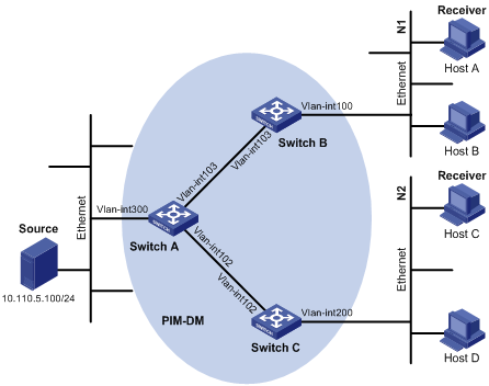
l As shown in Figure 1-2, Host A and Host C are multicast receivers in two stub networks N1 and N2.
l Switch A connects to the network that comprises the multicast source through VLAN-interface 300; Switch B connects to N1 through VLAN-interface 100; Switch C connects to N2 through VLAN-interface 200.
l It is required to configure PIM-DM to forward multicast traffic.
II. Network diagram
|
Device |
Interface |
IP address |
Device |
Interface |
IP address |
|
Switch A |
Vlan-int 300 |
10.110.5.101/24 |
Switch B |
Vlan-int 100 |
10.10.1.1/24 |
|
|
Vlan-int 102 |
10.110.6.1/24 |
|
Vlan-int 103 |
10.110.7.2/24 |
|
|
Vlan-int 103 |
10.110.7.1/24 |
|
|
|
|
Switch C |
Vlan-int 102 |
10.110.6.2/24 |
|
|
|
|
|
Vlan-int 200 |
10.10.2.1/24 |
|
|
|
Figure 1-2 Network diagram for PIM-DM configuration
III. Configuration procedure
1) Configure IP addresses and unicast routing
Configure an IP address and subnet mask for each interface as per Figure 1-2. Detailed configuration steps are omitted here.
Configure the OSPF protocol for interoperation among the switches in the PIM-DM domain for network-layer interoperation, and enable dynamic update of routing information among the switches through unicast routing. Detailed configuration steps are omitted here.
2) Enable IP multicast routing and enable PIM-DM on each interface
# On Switch B, enable multicast routing, enable PIM-DM on each interface, and enable IGMP on the interface connecting to N1.
<SwitchB> system-view
[SwitchB] multicast routing-enable
[SwitchB] interface vlan-interface 100
[SwitchB-Vlan-interface100] igmp enable
[SwitchB-Vlan-interface100] pim dm
[SwitchBA-Vlan-interface100] quit
[SwitchB] interface vlan-interface 103
[SwitchB-Vlan-interface103] pim dm
[SwitchB-Vlan-interface103] return
The configuration on Switch C is similar to that on Switch B.
# On Switch A, enable IP multicast routing and enable PIM-DM on each interface.
<SwitchA> system-view
[SwitchA] multicast routing-enable
[SwitchA] interface vlan-interface 300
[SwitchA-Vlan-interface300] pim dm
[SwitchA-Vlan-interface300] quit
[SwitchA] interface vlan-interface 103
[SwitchA-Vlan-interface103] pim dm
[SwitchA-Vlan-interface103] quit
[SwitchA] interface vlan-interface 102
[SwitchA-Vlan-interface102] pim dm
[SwitchA-Vlan-interface102] return
& Note:
You should enable PIM-DM on all interfaces with equal-cost routes, if any.
Chapter 2 PIM-SM Configuration
When configuring PIM-SM, go to the following sections for the information you are interested in:
l Displaying and Maintaining PIM-SM
l PIM-SM Configuration Example
2.1 PIM-SM Overview
2.1.1 Introduction to PIM-SM
Protocol Independent Multicast, Sparse Mode (PIM-SM) belongs to sparse mode multicast routing protocols. PIM-SM is mainly applicable to large-scale networks with broad scope in which group members are relatively sparse.
Different from the flood & prune principle of the dense mode, PIM-SM assumes that all hosts do not need to receive multicast packets, unless there is an explicit request for the packets.
PIM-SM uses the rendezvous point (RP) and the Bootstrap Router (BSR) to advertise multicast information to all PIM-SM routers and uses the join/prune information of the router to build the RP-rooted shared tree (RPT), thereby reducing the bandwidth occupied by data packets and control packets and reducing the process overhead of the router. Multicast data flows along the shared tree to the network segments the multicast group members are on. When the data traffic is sufficient, the multicast data flow can switch over to the Shortest Path Tree (SPT) rooted on the source to reduce network delay. PIM-SM does not depend on the specified unicast routing protocol but uses the present unicast routing table to perform the RPF check.
Note that, the creation and interaction of the RPs and BSRs are implemented through periodical RP advertisements and BSR Bootstrap packets respectively.
To make PIM-SM operate, you must configure candidate RPs and BSRs. BSRs collect and broadcast the information from candidate RPs.
2.1.2 PIM-SM Working Principle
The PIM-SM working process involves neighbor discovery, RPT building, multicast source registration, and SPT switchover. The neighbor discovery mechanism is the same as that of PIM-DM, which will not be described any more.
I. RPT building
When hosts join a multicast group G, the designated routers (DRs) connecting with the hosts send IGMP messages to learn the receivers of multicast group G. In this way, the leaf routers calculate the corresponding RP for multicast group G and then send join messages to the node of the next level toward the RP.
Each router along the path between a DR and the RP will generate (*, G) entries in the forwarding table, indicating that all packets sent to multicast group G are applicable to the entries no matter from which source they are sent. When the RP receives the packets sent to multicast group G, the packets will be sent to leaf routers along the path built and then reach the hosts. In this way, an RPT is built as shown in Figure 2-1.
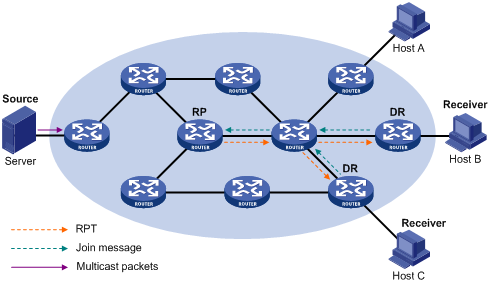
Figure 2-1 RPT schematic diagram
II. Multicast source registration
The purpose of multicast source registration is to inform the RP about the existence of a multicast source.
When multicast source S sends a multicast packet to the multicast group G, the PIM-SM multicast router directly connected to S will encapsulate the received packet into a registration packet and send it to the corresponding RP in unicast form. If there are multiple PIM-SM multicast routers on a network segment, the source-side DR will be responsible for sending the multicast packet.
When the RP receives the register message, it extracts the multicast packet from the register message and forwards the multicast packet down the RPT to the receivers, and sends an (S, G) join message hop by hop toward the multicast source. Thus, the routers along the path from the RP to the multicast source constitute an SPT branch. Each router on this branch creates an (S, G) entry in its forwarding table. The multicast source is the root, while the RP is the leaf of the SPT.
2.1.3 Configuration Prerequisites
I. Configuring candidate RPs
In a PIM-SM network, multiple candidate-RPs (C-RPs) can be configured. Each C-RP is responsible for forwarding multicast packets with the destination addresses in a certain range. Configuring multiple C-RPs is to implement load balancing of the RP. These C-RPs are equal. All multicast routers calculate the RPs corresponding to multicast groups using the same algorithm after receiving the C-RP messages that the BSR advertises.
![]() Caution:
Caution:
One RP can serve multiple multicast groups. Each multicast group can correspond to one unique RP, rather than multiple RPs.
II. Configuring BSRs
The BSR is the management core in a PIM-SM network. Candidate-RPs send announcement to the BSR, which is responsible for collecting and advertising the information about all candidate-RPs.
![]() Caution:
Caution:
There can be only one BSR in a network but you can configure multiple candidate-BSRs. In this case, once a BSR fails, you can switch over to another BSR. A BSR is elected among the C-BSRs automatically. The C-BSR with the highest priority is elected as the BSR. If the priority is the same, the C-BSR with the highest IP address is elected as the BSR.
III. Configuring static RP
The router that serves as the RP is the core router of multicast routes. If the dynamic RP elected by BSR mechanism is invalid for some reason, the static RP can be configured to specify RP. As the backup of dynamic RP, static RP improves network robustness and enhances the operation and management capability of multicast network.
2.2 PIM-SM Configuration
1) Basic PIM-SM configuration includes:
l Configuring the Hello Interval
2) Advanced PIM-SM configuration includes:
l Configuring the PIM-SM Domain Border
l Configuring the Filtering of Multicast Source/Group
l Configuring the Filtering of PIM Neighbors
l Configuring Filtering of the Register Messages from DRs
l Configuring the Aging Time of PIM-SM Routing Entries
l Limiting a Legal BSR Address Range
l Disabling RPT-to-SPT Switchover
l Clearing Multicast Route Entries from PIM Routing Table
![]() Caution:
Caution:
At least one router in an entire PIM-SM domain should be configured with C-RPs and C-BSRs.
2.2.1 Enabling Multicast Routing
Refer to Common Multicast Configuration in the IP Multicast Volume.
2.2.2 Enabling PIM-SM
This configuration can take effect only after multicast is enabled.
Perform the following operations in interface view to enable/disable PIM-SM:
|
To do... |
Use the command... |
|
Enable PIM-SM on an interface |
pim sm |
|
Disable PIM-SM on an interface |
undo pim sm |
Repeat the pim sm command to enable PIM-SM on other interfaces. Only one multicast routing protocol can be enabled on an interface at a time.
Once PIM-SM is enabled on an interface, PIM-DM cannot be enabled on the same interface and vice versa.
2.2.3 Entering PIM View
Refer to 1.2.4 “Entering PIM View”.
2.2.4 Configuring the Hello Interval
In general, PIM-SM broadcasts Hello packets on the PIM-SM-enabled port periodically to detect PIM neighbors and determine the designated router (DR).
For details, refer to section 1.2.3 “Configuring the Hello Interval”.
2.2.5 Configuring Candidate-BSRs
In a PIM domain, one or more candidate BSRs should be configured. A Bootstrap Router (BSR) is elected among candidate BSRs. The BSR takes charge of collecting and advertising RP information.
The automatic election among candidate BSRs is described as follows:
One interface which has started PIM-SM must be specified when configuring the router as a candidate BSR.
At first, each candidate BSR considers itself as the BSR of the PIM-SM domain, and sends Bootstrap message by taking the IP address of the interface as the BSR address.
When receiving Bootstrap messages from other routers, the candidate BSR will compare the BSR address of the newly received Bootstrap message with that of itself. Comparison standards include priority and IP address. The higher IP address is considered better when the priority is the same. If the priority of a candidate BSR is higher than that of others, this candidate BSR will replace its BSR address and stop regarding itself as the BSR. Otherwise, the candidate BSR will keep its BSR address and continue to regard itself as the BSR.
Perform the following operations in PIM view to configure/remove candidate-BSRs:
|
To do... |
Use the command... |
|
Configure a candidate-BSR |
c-bsr interface-type interface-number hash-mask-len [ priority ] |
|
Remove the candidate-BSR configured |
undo c-bsr |
Candidate-BSRs should be configured on the routers in the backbone network. By default, no BSR is set. The default priority is 0.
![]() Caution:
Caution:
One router can only be configured with one candidate-BSR. When a candidate-BSR is configured on another interface, it will replace the previous one.
2.2.6 Configuring Candidate-RPs
In PIM-SM, the shared tree built by multicast routing data is rooted at the RP. There is a mapping from a multicast group to an RP. A multicast group can be mapped to only one RP. Different multicast groups can be mapped to the same RP or different RPs.
Perform the following operations in PIM view to configure/remove candidate-RPs:
|
To do... |
Use the command... |
|
Configure a candidate-RP |
c-rp interface-type interface-number [ group-policy acl-number | priority priority-value ] * |
|
Remove the candidate-RP configured |
undo c-rp { interface-type interface-number | all } |
When configuring RP, if the range of the served multicast group is not specified, the RP will serve all multicast groups. Otherwise, the range of the served multicast group is the multicast group in the specified range. You are suggested to configure Candidate RP on the backbone router.
![]() Caution:
Caution:
Using the group-policy command on a candidate RP, you can configure only the permit rule. After the configuration of the permit rule, the RP only serves groups included in the permit rule.
2.2.7 Configuring a Static RP
To enhance network robustness, a static RP serves as the backup of dynamic RP
Follow these steps to configure a static RP:
|
To do... |
Use the command... |
Remarks |
|
Enter system view |
system-view |
— |
|
Enter PIM view |
pim |
— |
|
Configure static RP |
static-rp rp-address [ acl-number ] |
Required |
![]() Caution:
Caution:
l When the RP elected by BSR mechanism is effective, static RP does not work.
l All routers in the PIM domain must be configured with this command simultaneously, with the same RP address specified.
l The system supports up to ten different static RP addresses. When more than ten static RP addresses are configured, the system will give this prompt information: “Cannot config static-rp, exceeded static-rp limit 10”.
2.2.8 Configuring the PIM-SM Domain Border
After the PIM-SM domain border is configured, bootstrap messages can not cross the border in any direction. In this way, the PIM-SM domain can be split.
Perform the following operations in interface view to configure/remove the PIM-SM domain border:
|
To do... |
Use the command... |
|
Configure a PIM-SM domain border |
pim bsr-boundary |
|
Remove the PIM-SM domain border configured |
undo pim bsr-boundary |
By default, no domain border is set.
After the pim bsr-boundary command is performed, a bootstrap message can not cross the border but other PIM packets can. The pim bsr-boundary command can effectively divide a network into domains using different BSRs.
2.2.9 Configuring the Filtering of Multicast Source/Group
Refer to section 1.2.5 “Configuring the Filtering of Multicast Source/Group”.
2.2.10 Configuring the Filtering of PIM Neighbors
Refer to section 1.2.6 “Configuring the Filtering of PIM Neighbors”.
Refer to section 1.2.7 “Configuring the Maximum Number of PIM Neighbors on an Interface”.
2.2.11 Configuring Filtering of the Register Messages from DRs
In the PIM-SM network, the register message filtering mechanism can control sources to send messages to groups on the RP, i.e., the RP can filter the register messages from DRs but accept specified messages only.
Perform the following operations in PIM view to configure/remove filtering of the register messages:
|
To do... |
Use the command... |
|
Configure register message filtering |
register-policy acl-number |
|
Remove the configured register message filtering policy |
undo register-policy |
If an entry of a source group is denied by the ACL, or the ACL does not define operation to it, or there is no ACL defined, the RP will send RegisterStop messages to the DR to prevent the register process of the multicast data stream.
![]() Caution:
Caution:
Only the register messages matching the ACL permit clause can be accepted by the RP. Specifying an undefined ACL will make the RP deny all register messages.
2.2.12 Configuring the Aging Time of PIM-SM Routing Entries
I. Introduction
In practice, the number of multicast streams may exceed the number of PIM-SM routing table entries. Therefore, some multicast streams cannot be correctly forwarded.
If a receiver requests only part of multicast streams at one time, that is, periodical polling request, you can configure the aging time of PIM-SM routing entries to be less than the default 210 seconds, so that multicast table entries that are no longer used for forwarding multicast streams can be timely aged out to release system resources. As a result, multicast streams can be normally forwarded without adding PIM-SM routing table entries.
II. Configuration prerequisites
l Enable multicast globally.
l Configure at least one PIM-SM interface.
![]() Caution:
Caution:
Aging time of PIM-SM routing table entries needs to be configured only when necessary; otherwise, some routing entries may be deleted by mistake.
III. Configuration procedure
Follow these steps to configure the aging time of PIM-SM routing entries:
|
To do… |
Use the command… |
|
|
Enter system view |
system-view |
— |
|
Enable multicast routing globally |
multicast routing-enable |
Required |
|
Enter interface view |
interface interface-type interface-number |
— |
|
Configure an IP address |
ip address ip-address { mask | mask-length } [ sub ] |
Required |
|
Enable PIM-SM |
pim sm |
Required |
|
Return to system view |
quit |
— |
|
Enter PIM view |
pim |
— |
|
Configure the aging time of PIM-SM routing entries |
pim-sm routing-table aging-time time-value |
Optional The default value is 210 seconds. |
![]() Caution:
Caution:
l If you need to configure the aging time of PIM-SM routing table entries on the RP, do it according to the number of PIM-SM routing table entries. A larger number of entries requires a longer aging time, the minimum aging time must not be smaller than the register suppression period (60 seconds) of PIM-SM; otherwise PIM-SM routing table entries on the RP may be aged in case that there are no receivers.
l After you use the undo pim command, disable multicast globally, or delete the last PIM-SM-enabled interface, the device resets the configured aging time of PIM-SM routing entries to the default value (210 seconds).
l For boards suffixed with DA/DB/DC, if the configured aging time of PIM-SM routing table entries is smaller than 210 seconds, the error will be around 30 seconds; for boards suffixed with C/CA/CB, the error may be greater than 30 seconds.
l If the configured aging time of PIM-SM routing table entries is greater than or equal to the default value (210 seconds), the error may be greater than 30 seconds.
2.2.13 Limiting a Legal BSR Address Range
To prevent the legal BSR from being replaced maliciously in the network, you can limit a legal BSR address range. BSR messages from beyond the configured address range will not be accepted by routers.
Perform the following operations in PIM view to configure/restore the legal BSR range:
|
To do... |
Use the command... |
|
Configure a legal BSR range |
bsr-policy acl-number |
|
Restore to the default setting |
undo bsr-policy |
2.2.14 Limiting a Legal C-RP Range
To avoid C-RP spoofing, you can limit the range of legal C-RP and limit the groups that each C-RP servers.
Perform the following operations in PIM view to configure/restore the legal C-RP range:
|
To do... |
Use the command... |
|
Configure a legal C-RP range |
crp-policy acl-number |
|
Restore to the default setting |
undo crp-policy |
For detailed information of crp-policy, refer to the PIM Commands.
2.2.15 Disabling RPT-to-SPT Switchover
RPT is not necessarily the tree that has the shortest path. When the multicast traffic rate becomes high, the forwarding path will be switched from RPT to SPT, which is the shortest forwarding path. If an S9500 series routing switch acts as the receiver-side DR, it initiates an RPT-to-SPT switchover process (by default) upon receiving the first multicast packet along the RPT. You can disable the switchover from RPT to SPT.
Perform the following operations to disable the RPT-to-SPT switchover:
|
To do… |
Use the command… |
Remarks |
|
Enter system view |
system-view |
— |
|
Enter PIM view |
pim |
— |
|
Disable RPT-to-SPT switchover |
spt-switch-threshold [ value | infinity ] [ group-policy acl-number [ order order-value ] ] |
Required By default, the device initiates RPT-to-SPT switchover upon receiving the first multicast packet. |
![]() Caution:
Caution:
RPT-to-SPT switchover cannot be disabled on a static RP or C-RP; otherwise, the device will fail to forward multicast packets.
2.2.16 Configuring SSM Mapping
In the SSM model, multicast receivers need to support IGMPv3 so that Layer 3 multicast devices on the same subnet can learn the information of multicast sources specified by the receivers. Multicast receivers running IGMPv1 or IGMPv2 cannot meet the requirements for implementing the SSM model.
However, the SSM mapping feature can solve this issue by configuring SSM mapping rules on Layer 3 multicast devices, enabling IGMPv1/v2 receivers to support the SSM model.
A mapping rule associates a multicast source with a multicast group or group range. Therefore, you can configure multiple rules to map multiple multicast sources to a multicast group or group range.
Follow these steps to configure the SSM mapping rules
|
To do… |
Use the command… |
Remarks |
|
Enter system view |
system-view |
— |
|
Configure an SSM mapping rule |
ssm-mapping group-address { mask | mask-length } source-address |
Required No SSM mapping is configured by default. |
![]() Caution:
Caution:
l Ensure the multicast source addresses are correct when configuring the SSM mapping rules.
l When configuring the SSM mapping rules, delete the (*, G) entries matching the configured group address or group address range; otherwise, some (*, G) entries may not time out.
l Up to 128 SSM mappings can be supported.
l The (S, G) entries matching the configured SSM mapping rules may exceed the system specification and thus affect the normal transfer of multicast traffic.
2.2.17 Clearing Multicast Route Entries from PIM Routing Table
Refer to section 1.2.8 “Clearing PIM Routing Table Entries”.
2.2.18 Clearing PIM Neighbors
Refer to 1.2.9 “Clearing PIM Neighbors”.
2.3 Displaying and Maintaining PIM-SM
|
To do... |
Use the command... |
Remarks |
|
Display the BSR information |
display pim bsr-info |
Available in any view |
|
Display the RP information |
display pim rp-info [ group-address ] |
|
|
Enable the PIM-SM debugging |
debugging pim sm { all | mbr { alert | fresh } | verbose | mrt | msdp | timer { assert | bsr | crpadv | jp | jpdelay | mrt | probe | spt } | warning | { recv | send } { assert | bootstrap | crpadv | jp | reg | regstop } |
Available in user view |
|
Disable the PIM-SM debugging |
undo debugging pim sm { all | mbr { alert | fresh } | verbose | mrt | msdp | timer { assert | bsr | crpadv | jp | jpdelay | mrt | probe | spt } | warning | { recv | send } { assert | bootstrap | crpadv | jp | reg | regstop } |
2.4 PIM-SM Configuration Example
I. Network requirements
l Receivers receive information through multicast. The entire PIM domain operates in the sparse mode.
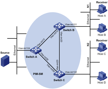
l As shown in Figure 2-2, Host A and Host C are multicast receivers in two stub networks N1 and N2.
l Switch A connects to the network that comprises the multicast source through VLAN-interface 104; Switch B connects to N1 through VLAN-interface 101; Switch C connects to N2 through VLAN-interface 102.
l It is required to configure PIM-SM to forward multicast traffic.
II. Network diagram
|
Device |
Interface |
IP address |
Device |
Interface |
IP address |
|
Switch A |
Vlan-int104 |
104.0.0.1/24 |
Switch B |
Vlan-int10 |
10.0.0.2/24 |
|
|
Vlan-int10 |
10.0.0.1/24 |
|
Vlan-int20 |
20.0.0.1/24 |
|
|
Vlan-int30 |
30.0.0.1/24 |
|
Vlan-int101 |
101.0.0.1/24 |
|
Switch C |
Vlan-int102 |
102.0.0.1/24 |
|
|
|
|
|
Vlan-int20 |
20.0.0.2/24 |
|
|
|
|
|
Vlan-int30 |
30.0.0.2/24 |
|
|
|
Figure 2-2 Network diagram for PIM-SM configuration
III. Configuration procedure
1) Configure IP addresses and unicast routing
Configure an IP address and subnet mask for each interface as per Figure 2-2. Detailed configuration steps are omitted here.
Configure the OSPF protocol for interoperation among the switches in the PIM-SM domain for network-layer interoperation, and enable dynamic update of routing information among the switches through unicast routing. Detailed configuration steps are omitted here.
2) Configure Switch A
# Enable multicast routing globally.
<SwitchA> system-view
[SwitchA] multicast routing-enable
# Configure Loopback 0 as a C-BSR and the RP, and enable PIM-SM on the interface.
[SwitchA] interface loopback 0
[SwitchA-LoopBack0] ip address 1.1.1.1 32
[SwitchA-LoopBack0] pim sm
# Enable PIM-SM on all VLAN interfaces.
[SwitchA] interface vlan-interface 104
[SwitchA-Vlan-interface104] pim sm
[SwitchA-Vlan-interface104] quit
[SwitchA] interface vlan-interface 10
[SwitchA-Vlan-interface10] pim sm
[SwitchA-Vlan-interface10] quit
[SwitchA] interface vlan-interface 30
[SwitchA-Vlan-interface30] pim sm
[SwitchA-Vlan-interface30] quit
# Configure the C-BSR and RP.
[SwitchA] pim
[SwitchA-pim] c-bsr LoopBack 0 32
[SwitchA-pim] c-rp LoopBack 0
[SwitchA-pim] quit
# Configure OSPF for unicast routing.
[SwitchA] ospf
[SwitchA-ospf-1] import-route direct
[SwitchA-ospf-1] area 0.0.0.0
[SwitchA-ospf-1-area-0.0.0.0] network 1.1.1.1 0.0.0.0
[SwitchA-ospf-1-area-0.0.0.0] network 10.0.0.0 0.0.0.255
[SwitchA-ospf-1-area-0.0.0.0] network 30.0.0.0 0.0.0.255
3) Configure Switch B.
<SwitchB> system-view
[SwitchB] multicast routing-enable
[SwitchB] interface vlan-interface 101
[SwitchB-Vlan-interface101] pim sm
[SwitchB-Vlan-interface101] igmp enable
[SwitchB-Vlan-interface101] quit
[SwitchB] interface vlan-interface 10
[SwitchB-Vlan-interface10] pim sm
[SwitchB-Vlan-interface10] quit
[SwitchB] interface vlan-interface 20
[SwitchB-Vlan-interface20] pim sm
# Configure Switch C.
<SwitchC> system-view
[SwitchC] multicast routing-enable
[SwitchC] interface vlan-interface 102
[SwitchC-Vlan-interface102] pim sm
[SwitchC-Vlan-interface102] igmp enable
[SwitchC-Vlan-interface102] quit
[SwitchC] interface vlan-interface 20
[SwitchC-Vlan-interface20] pim sm
[SwitchC-Vlan-interface20] quit
[SwitchC] interface vlan-interface 30
[SwitchC-Vlan-interface30] pim sm
& Note:
You should enable PIM-SM on all interfaces with equal-cost routes, if any.