- Table of Contents
- Related Documents
-
| Title | Size | Download |
|---|---|---|
| 08-MBGP Configuration | 103.24 KB |
Chapter 1 MBGP Multicast Extension Configuration
1.1 MBGP Multicast Extension Overview
1.1.1 MBGP Extension Attributes for Multicast
1.1.2 MBGP Operating Mode and Message Type
1.2 MBGP Multicast Extension Configuration
1.2.1 Enabling MBGP Multicast Extension Protocol
1.2.2 Configuring Network Routes Notified by MBGP Multicast Extension
1.2.3 Configuring the MED Value for an AS
1.2.4 Comparing MED Values from Different AS Neighbor Paths
1.2.5 Configuring Local Preference
1.2.7 Configuring MBGP Peer (Group)
1.2.8 Configuring the Maximum Number of Routes a Peer Group can Receive
1.2.9 Configuring MBGP Route Aggregation
1.2.10 Configuring an MBGP Route Reflector
1.2.11 Configure MBGP Community Attributes
1.2.12 Importing IGP Routing Information into MBGP
1.2.13 Defining AS Path List and Routing Policy
1.2.14 Configuring MBGP Route Filtering
1.2.15 Resetting BGP Connections
1.3 Displaying and Maintaining MBGP Configuration
1.4 MBGP Multicast Extension Configuration Example
Chapter 1 MBGP Multicast Extension Configuration
When configuring MBGP, go to these sections for information you are interested in:
l MBGP Multicast Extension Overview
l MBGP Multicast Extension Configuration
l Displaying and Maintaining MBGP Configuration
l MBGP Multicast Extension Configuration Example
1.1 MBGP Multicast Extension Overview
At present, the most widely used inter-domain unicast routing protocol is BGP-4. Because the multicast topology may be different from the unicast topology, BGP-4 must be modified in order to implement the transmission of inter-domain multicast routing information. Some routers in the network may only support unicast rather than multicast and may not forward multicast packets since the particular policy requires that. To construct inter-domain multicast routing trees, you need to know the unicast routing information as well as the information of multicast-supporting parts of the network, namely, the multicast network topology.
BGP-4 has been proved to be an effective and stable inter-domain unicast routing protocol. Therefore, it is more rational to enhance and extend the BGP-4 protocol than to construct a new protocol. RFC2858 defines an extended BGP-4, Multi-Protocol BGP (MP-BGP), to provide routing information in use for multiple routing applications. MBGP can not only carry IPv4 unicast routing information but also the routing information of other network layer protocols (such as multicast, IPv6). Carrying multicast routing information is only one of the extended functions.
MBGP enables unicast and multicast routing information to be exchanged through the same process but stored in different routing tables. As MBGP is an enhanced version of BGP-4, all the common policies and configuration methods that BGP-4 supports can be applied to multicast.
This chapter describes mainly MBGP extension for multicast.
1.1.1 MBGP Extension Attributes for Multicast
To make MBGP support multicast, RFC2858 defines two new route attributes in the UPDATE message: MP_REACH_NLRI (multiprotocol reachable NLRI) and MP_UNREACH_NLRI (multiprotocol unreachable NLRI). They are all optional non-transitive attributes, that is, routers that do not support MBGP can ignore the attributes and do not forward the attributes.
Among the information carried by MP_REACH_NLRI and MP_UNREACH_NLRI, address family identifier (AFI) and subsequent address family identifier (SAFI) can identify the address family of the information. SAFI is a complement to network layer reachability information (NLRI), with the value 1 for the unicast mode of NLRI, and the value 2 for the multicast mode of NLRI.
I. MP_REACH_NLRI attribute
MP_REACH_NLRI is an optional non-transitive attribute, and can be used to:
l Send the routing information of a new reachable protocol.
l Send the next hop information about the new protocol with the same coding mode as that of NLRI.
l Enable the router to report part or all of the sub-network points of attachment (SNPAs) saved in the local system.
II. MP_UNREACH_NLRI attribute
The MP_UNREACH_NLRI is an optional non-transitive attribute that can be used for the purpose of withdrawing one or multiple unfeasible routes. It includes the following fields:
l AFI and SAFI.
l Withdrawn Routes: Contains one or multiple NLRIs, in which are the unreachable destination addresses.
An UPDATE packet that contains the MP_UNREACH_NLRI is not required to carry any other path attributes.
These two attributes enables MBGP to carry multi-protocol information. MBGP therefore supports both unicast and multicast by constructing different topology maps to implement appropriate policies. Besides, MBGP may construct different inter-domain routes for unicast and multicast under a same policy.
1.1.2 MBGP Operating Mode and Message Type
MBGP runs on a router in the following two modes:
l Internal BGP (IBGP )
l External BGP (EBGP )
MBGP running in an autonomous system is called IBGP; MBGP running across autonomous systems is called EBGP.
MBGP offers four types of messages:
l Open Message: First message sent after the TCP connection is established.
l Notification Message: Error notification message.
l Keepalive Message: Message used to check the validity of the connection.
l Update Message: Most important information in the MBGP system, used to exchange routing information among peers. It consists of three parts at the most: MP_UNREACH_NLRI, Path Attributes, and MP_REACH_NLRI.
1.2 MBGP Multicast Extension Configuration
Basic configuration tasks of MBGP multicast extension include
l Enabling MBGP Multicast Extension Protocol
l Configuring Network Routes Notified by MBGP Multicast Extension
Advanced configuration tasks of MBGP multicast extension include
l Configuring the MED Value for an AS
l Comparing MED Values from Different AS Neighbor Paths
l Configuring Local Preference
l Configuring MBGP Peer (Group)
l Configuring the Maximum Number of Routes a Peer Group can Receive
l Configuring MBGP Route Aggregation
l Configuring an MBGP Route Reflector
l Configure MBGP Community Attributes
l Importing IGP Routing Information into MBGP
l Defining AS Path List and Routing Policy
l Configuring MBGP Route Filtering
& Note:
Only configuration tasks in IPv4 multicast sub-address family view are detailed below. Other tasks configured in BGP or system view are only briefed. For the detailed configuration, refer to BGP Configuration and Route Policy Configuration in the IP Routing Volume.
1.2.1 Enabling MBGP Multicast Extension Protocol
To enable the MBGP multicast extension protocol, enter IPv4 multicast sub-address family view.
A router does not start receiving MBGP connection requests immediately the MBGP multicast extension protocol is enabled. To activate a router to originate MBGP connection requests to neighboring routers, refer to the neighbor configuration.
Follow these steps to enable MBGP multicast extension protocol:
|
To do... |
Use the command... |
|
Enter the MBGP multicast address family view |
ipv4-family multicast |
|
Remove the MBGP multicast address family view |
undo ipv4-family multicast |
By default, the system does not run the MBGP multicast extension protocol.
1.2.2 Configuring Network Routes Notified by MBGP Multicast Extension
The network command is used to configure the network routes to be advertised to MBGP peers, as well as the mask and route policy of this network route.
Perform the following operation in IPv4 multicast sub-address family view to configure/remove network routes to be advertised by MBGP multicast extension:
|
To do... |
Use the command... |
|
Configure the network routes to be advertised by the local MBGP |
network ip-address [ address-mask ] [ route-policy route-policy-name ] |
|
Remove the network routes to be advertised by the local MBGP |
undo network ip-address [ address-mask ] [ route-policy route-policy-name ] |
By default, no route is advertised by the local MBGP.
The network command advertises only the precisely matched route, the one with prefix and mask completely conforming to the configuration. If no mask is specified, match goes by the natural network segment.
1.2.3 Configuring the MED Value for an AS
The MED configured in BGP view is valid for both unicast and multicast.
For details of this configuration, refer to BGP Configuration in the IP Routing Volume.
1.2.4 Comparing MED Values from Different AS Neighbor Paths
Do not use this configuration unless you are sure that different ASs adopt the same IGP and route selection method. The configuration in BGP view works both in unicast and multicast.
For details of this configuration, refer to BGP Configuration in the IP Routing Volume.
1.2.5 Configuring Local Preference
Different local preferences can be configured as a reference of the MBGP route selection. When an MBGP router gets routes with the same destination but different next hops through different neighbors, it will choose the route with the highest local preference.
The configuration works both in unicast and multicast.
For details of this configuration, refer to BGP Configuration in the IP Routing Volume.
1.2.6 Configuring MBGP Timer
After a router establishes an MBGP connection with a peer, it sends Keepalive messages to the peer periodically to check for the smooth connection. If the router does not receive any Keepalive message or any other kind of message from the peer within the defined connection Holdtime, it will think the MBGP connection broken and exit, and will process the routing information received through this connection as appropriate. Therefore, the Keepalive interval and MBGP connection Holdtime are two parameters of great importance in MBGP mechanism.
The configuration works both in unicast and multicast.
For details of this configuration, refer to BGP Configuration in the IP Routing Volume.
1.2.7 Configuring MBGP Peer (Group)
The use of MBGP peer groups is to simplify configuration. When configuring MBGP peers, you can create and configure a peer group in BGP view, and then add the peers into the group, since all peers in a group have the same configuration with the group. Then, enable this peer group in IPv4 multicast sub-address family view and add peers to this peer group to create MBGP peers and an MBGP peer group. In conclusion, to create MBGP peers/peer groups, you must configure them successfully in BGP view first.
![]() Caution:
Caution:
Configure peer groups under the guide of technical support engineers.
I. Creating a peer group with members
Configure a MBGP peer group in BGP view and add peers to this peer group. For details, refer to BGP Configuration in the IP Routing Volume.
II. Enabling a peer (group)
Perform the following operation in IPv4 multicast sub-address family view to enable/disable a peer (group):
|
To do... |
Use the command... |
|
Enable the specified peer (group) |
peer group-name enable |
|
Disable the specified peer (group) |
undo peer group-name enable |
III. Adding an MBGP peer to the group
Perform the following operation in IPv4 multicast sub-address family view to add/delete an MBGP peer to/from the group:
|
To do... |
Use the command... |
|
Add an MBGP peer to the group |
peer peer-address group group-name |
|
Delete the MBGP peer |
undo peer peer-address |
IV. Advertising MBGP community attributes to a peer (group)
Perform the following operation in IPv4 multicast sub-address family view to advertise/not to advertise the community attributes to a peer (group):
|
To do... |
Use the command... |
|
Advertise the community attributes to a peer (group) |
peer group-name advertise-community |
|
Configure not to advertise the community attributes to a peer (group) |
undo peer group-name advertise-community |
By default, no community attribute is advertised to any peer (group).
V. Configuring a peer (group) as an MBGP route reflector client
Perform the following operation in IPv4 multicast sub-address family view to configure a peer (group) as an MBGP route reflector client or remove the configuration:
|
To do... |
Use the command... |
|
Configure a peer (group) as an MBGP route reflector client |
peer group-name reflect-client |
|
Remove the above configuration |
undo peer group-name reflect-client |
By default, there is no route reflector in an AS.
It is generally unnecessary to configure this command for a peer group. This command is reserved for the occasional compatibility with the network equipments of other vendors.
VI. Configuring the local address as the next hop when advertising routes
This involves removing the next hop configuration in the routing information advertised to a peer (group) and configuring the local address as the next hop address. It is valid only for IBGP peers/peer groups.
Perform the following operation in IPv4 multicast sub-address family view to configure the local address as the next hop when advertising routes or remove the configuration:
|
To do... |
Use the command... |
|
Configure the local address as the next hop when advertising routing information |
peer group-name next-hop-local |
|
Remove the above configuration |
undo peer group-name next-hop-local |
VII. Specifying the routing policy for a peer (group)
Perform the following operation in IPv4 multicast sub-address family view to specify/remove the routing policy for a peer (group):
|
To do... |
Use the command... |
|
Configure routing policy for incoming packets |
peer { group-name | peer-address } route-policy policy-name import |
|
Remove incoming policy configuration |
undo peer { group-name | peer-address } route-policy policy-name import |
|
Configure routing policy for outgoing packets |
peer group-name route-policy policy-name export |
|
Remove outgoing policy configuration |
undo peer group-name route-policy policy-name export |
By default, no routing policy is specified for any peer (group).
VIII. Configuring IP-ACL-based route filtering policy for a peer (group)
Perform the following operation in IPv4 multicast sub-address family view to configure/remove IP-ACL-based route filtering policy for a peer (group):
|
To do... |
Use the command... |
|
Configure filtering policy for incoming packets |
peer { group-name | peer-address } filter-policy acl-number import |
|
Remove incoming policy configuration |
undo peer { group-name | peer-address } filter-policy acl-number import |
|
Configure routing policy for outgoing packets |
peer group-name filter-policy acl-number export |
|
Remove outgoing policy configuration |
undo peer group-name filter-policy acl-number export |
By default, a peer (group) does not perform route filtering based on the IP ACL.
IX. Configuring AS-path-list-based route filtering policy for a peer (group)
Perform the following operation in IPv4 multicast sub-address family view to configure/remove the AS-path-list-based route filtering policy for a peer (group):
|
To do... |
Use the command... |
|
Configure filtering policy for incoming packets |
peer { group-name | peer-address } as-path-acl acl-number import |
|
Remove incoming policy configuration |
undo peer { group-name | peer-address } as-path-acl acl-number import |
|
Configure routing policy for outgoing packets |
peer { group-name | peer-address } as-path-acl acl-number export |
|
Remove outgoing policy configuration |
undo peer { group-name | peer-address }as-path-acl acl-number export |
By default, a peer (group) does not perform route filtering based on the AS path list.
X. Configuring prefix-list-based route filtering policy for a peer (group)
Perform the following operation in IPv4 multicast sub-address family view to configure/remove prefix-list-based route filtering policy for a peer (group):
|
To do... |
Use the command... |
|
Configure filtering policy for incoming packets |
peer { group-name | peer-address } ip-prefix prefixname import |
|
Remove incoming policy configuration |
undo peer { group-name | peer-address } ip-prefix prefixname import |
|
Configure routing policy for outgoing packets |
peer {group-name ip-prefix prefixname export |
|
Remove outgoing policy configuration |
undo peer group-name ip-prefix prefixname export |
By default, a peer (group) does not perform route filtering based on the prefix list.
1.2.8 Configuring the Maximum Number of Routes a Peer Group can Receive
|
To do... |
Use the command... |
|
Configure the maximum number of routes that can be received by a peer group |
peer { group-name | peer-address } route-limit route-limit-value [ route-limit-percent ] [ alter-only | idle-forever | idle-timeout timeout-value ] |
|
Restore the maximum number of routes that can be received by a peer group |
undo peer { group-name | peer-address } route-limit |
1.2.9 Configuring MBGP Route Aggregation
MBGP supports the manual aggregation of routes. Manual aggregation aggregates the local MBGP routes. A series of parameters can be configured during manual route aggregation.
Perform the following operation in IPv4 multicast sub-address family view to configure/remove MBGP route aggregation:
|
To do... |
Use the command... |
|
Configure the aggregation of local routes |
aggregate address mask [ as-set | attribute-policy route-policy-name | detail-suppressed | origin-policy route-policy-name | suppress-policy route-policy-name ] * |
|
Remove the aggregation of local routes |
undo aggregate address mask [ as-set | attribute-policy route-policy-name | detail-suppressed | origin-policy route-policy-name | suppress-policy route-policy-name ] * |
By default, MBGP does not aggregate local routes.
1.2.10 Configuring an MBGP Route Reflector
To ensure the interconnectivity among MBGP peers, it is necessary to establish fully-closed network among IBGP multicast peers. However, some internal MBGP multicast networks are very large, and it costs a good sum to establish a fully-closed network.
Route reflector solves this problem. The core is to specify a router as the focus of the internal sessions. Multiple MBGP multicast routers can be peers of one central point, namely a multiple route reflector, which in turn creates peer relationship with other reflectors. The route reflector is the focus of other routers. The routers other than those reflectors are called clients. The clients are in peer with route reflects and exchange routing information with them. The route reflectors transfer (reflect) information between the clients in turn.
For the details of the principles and configurations, refer to BGP Configuration in the IP Routing Volume.
1.2.11 Configure MBGP Community Attributes
Within the MBGP, a community is a set of destinations with some characteristics in common. A community is not limited to a network, or an AS has no physical boundary.
For details, refer to BGP Configuration in the IP Routing Volume.
1.2.12 Importing IGP Routing Information into MBGP
MBGP can advertise intra-area network information to other ASs. To this end, you can use MBGP to advertise the intra-area network information that local router gets through IGP routing protocol.
Perform the following operation in IPv4 multicast sub-address family view to import/delete IGP routing information:
|
To do... |
Use the command... |
|
Import IGP Routing Information into MBGP |
import-route protocol [ route-policy policy-name ] [ med med-value ] * |
|
Delete the imported IGP routing information |
undo import-route protocol |
By default, MBGP does not import any route of other protocols.
Parameter Protocol specifies the source routing protocols of import, which can be direct, static, rip, isis, ospf, ospf-ase or ospf-nssa at present.
1.2.13 Defining AS Path List and Routing Policy
To configure AS path list and routing polity you need to:
l Configure the regular expression of autonomous systems (in system view);
The UPDATE information of MBGP contains an AS_PATH domain. The autonomous system paths for MBGP routing information exchange is recorded in this domain.
l Define the routing policy (in system view);
l Define matching rules (in routing policy view);
l Define value assigning rules (in routing policy view)
For the detailed configuration of regular expression of AS, refer to BGP Configuration in the IP Routing Volume. For other configurations, refer to Route Policy Configuration in the IP Routing Volume.
1.2.14 Configuring MBGP Route Filtering
The route filtering configuration of MBGP is the same as that of unicast BGP.
For details, refer to BGP Configuration in the IP Routing Volume.
1.2.15 Resetting BGP Connections
After changing the MBGP policy or protocol configuration, users must disconnect the present BGP connection to make the new configuration effective.
For details, refer to BGP Configuration in the IP Routing Volume.
1.3 Displaying and Maintaining MBGP Configuration
|
To do... |
Use the command... |
Remarks |
|
Display an MBGP routing table |
display bgp multicast routing-table [ ip-address [ mask ] ] |
Available in any view |
|
Display CIDR (classless inter-domain routing) |
display bgp multicast routing-table cidr |
|
|
Display the routing information about the specified MBGP community |
display bgp multicast routing-table community [ aa:nn | no-export-subconfed | no-advertise | no-export ] * [ whole-match ] |
|
|
Display the routes permitted by the specified MBGP community list |
display bgp multicast routing-table community-list community-list-number [ whole-match ] |
|
|
Display the routes with inconsistent source autonomous systems |
display bgp multicast routing-table different-origin-as |
|
|
Display the routing information to or from a specified multicast neighbor |
display bgp multicast peer [ peer-address ] [ verbose ] |
|
|
Display the routing information advertised by MBGP |
display bgp multicast network |
|
|
Display the peer group information |
display bgp multicast group [ group-name ] |
|
|
Display the AS path information matching the AS regular expression |
display bgp multicast routing-table regular-expression as-regular-expression |
|
|
Enable debugging MBGP update packets |
debugging bgp mp-update [ receive | send ] [ verbose ] |
Available in user view |
1.4 MBGP Multicast Extension Configuration Example
I. Network requirement
This example describes how the administrator uses the MBGP attributes to manage route selection. All switches are configured with MBGP. The IGP in AS200 uses OSPF. Switch A is in AS100 and serves as the MBGP neighbor of Switch B and Switch C in AS200. Switch B and Switch C run IBGP for Switch D in AS200.
II. Network diagram
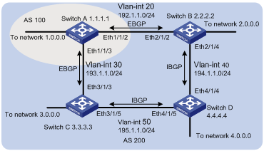
Figure 1-1 Network diagram for MBGP path selection configuration
III. Configuration procedure
1) Configure Switch A
<SwitchA> system-view
System View: return to User View with Ctrl+Z.
[SwitchA] vlan 20
[SwitchA-vlan20] port ethernet1/1/2
[SwitchA-vlan20] quit
[SwitchA] interface vlan-interface 20
[SwitchA-Vlan-interface20] ip address 192.1.1.1 255.255.255.0
[SwitchA-Vlan-interface20] quit
[SwitchA] vlan 30
[SwitchA-vlan30] port ethernet1/1/3
[SwitchA-vlan30] quit
[SwitchA] interface vlan-interface 30
[SwitchA-Vlan-interface30] ip address 193.1.1.1 255.255.255.0
[SwitchA-Vlan-interface30] quit
# Enable MBGP.
[SwitchA] bgp 100
[SwitchA-bgp] ipv4-family multicast
# Specify the target network for MBGP.
[SwitchA-bgp-af-mul] network 1.0.0.0
[SwitchA-bgp-af-mul] network 2.0.0.0
[SwitchA-bgp-af-mul] quit
# Configure peers relationship.
[SwitchA-bgp] bgp 100
[SwitchA-bgp] group a1 external
[SwitchA-bgp] peer 192.1.1.2 group a1 as-number 200
[SwitchA-bgp] group a2 external
[SwitchA-bgp] peer 193.1.1.2 group a2 as-number 200
[SwitchA-bgp] ipv4-family multicast
[SwitchA-bgp-af-mul] peer a1 enable
[SwitchA-bgp-af-mul] peer a2 enable
# Configure the MED attribute of Switch A.
l Add an ACL on Switch A to permit network 1.0.0.0/8.
[SwitchA] acl number 2000
[SwitchA-acl-basic-2000] rule permit source 1.0.0.0 0.255.255.255
[SwitchA-acl-basic-2000] rule deny source any
l Define two routing policies: set_med_50 and set_med_100, providing two MED values for network 1.0.0.0 (50 and 100 respectively).
[SwitchA] route-policy set_med_50 permit node 10
[SwitchA-route-policy] if-match acl 2000
[SwitchA-route-policy] apply cost 50
[SwitchA-route-policy] quit
[SwitchA] route-policy set_med_100 permit node 10
[SwitchA-route-policy] if-match acl 2000
[SwitchA-route-policy] apply cost 100
l Apply the routing policy set_med_50 to the exported route updates of Switch C (193.1.1.2). Apply the routing policy set_med_100 to the exported route updates of Switch B (192.1.1.2).
[SwitchA] bgp 100
[SwitchA-bgp] ipv4-family multicast
[SwitchA-bgp-af-mul] peer a2 route-policy set_med_50 export
[SwitchA-bgp-af-mul] peer a1 route-policy set_med_100 export
2) Configure Switch B
<SwitchB> system-view
System View: return to User View with Ctrl+Z.
[SwitchB] vlan 20
[SwitchB-vlan20] port ethernet2/1/2
[SwitchB-vlan20] quit
[SwitchB] interface vlan-interface 20
[SwitchB-Vlan-interface20] ip address 192.1.1.2 255.255.255.0
[SwitchB-Vlan-interface20] quit
[SwitchB] vlan 40
[SwitchB-vlan40] port ethernet2/1/4
[SwitchB-vlan40] quit
[SwitchB] interface vlan-interface 40
[SwitchB-Vlan-interface40] ip address 194.1.1.2 255.255.255.0
[SwitchB-Vlan-interface40] quit
[SwitchB] ospf
[SwitchB-ospf-1] area 0
[SwitchB-ospf-1-area-0.0.0.0] network 194.1.1.0 0.0.0.255
[SwitchB-ospf-1-area-0.0.0.0] network 192.1.1.0 0.0.0.255
[SwitchB-ospf-1-area-0.0.0.0] quit
[SwitchB-ospf-1] quit
[SwitchB] bgp 200
[SwitchB-bgp] undo synchronization
[SwitchB-bgp] group b1 external
[SwitchB-bgp] peer 192.1.1.1.1 group b1 as-number 100
[SwitchB-bgp] group b2 internal
[SwitchB-bgp] peer 194.1.1.1.1 group b2
[SwitchB-bgp] peer 195.1.1.1.2 group b2
[SwitchB-bgp] ipv4-family multicast
[SwitchB-bgp-af-mul] peer b1 enable
[SwitchB-bgp-af-mul] peer b2 enable
3) Configure Switch C
<SwitchC> system-view
System View: return to User View with Ctrl+Z.
[SwitchC] vlan 30
[SwitchC-vlan30] port ethernet3/1/3
[SwitchC-vlan30] quit
[SwitchC] interface vlan-interface 30
[SwitchC-Vlan-interface30] ip address 193.1.1.2 255.255.255.0
[SwitchC-Vlan-interface30] quit
[SwitchC] vlan 50
[SwitchC-vlan50] port ethernet3/1/5
[SwitchC-vlan50] quit
[SwitchC] interface vlan-interface 50
[SwitchC-Vlan-interface50] ip address 195.1.1.2 255.255.255.0
[SwitchC-Vlan-interface50] quit
[SwitchC] ospf
[SwitchC-ospf-1] area 0
[SwitchC-ospf-1-area-0.0.0.0] network 193.1.1.0 0.0.0.255
[SwitchC-ospf-1-area-0.0.0.0] network 195.1.1.0 0.0.0.255
[SwitchC-ospf-1-area-0.0.0.0] quit
[SwitchC-ospf-1] quit
[SwitchC] bgp 200
[SwitchC-bgp] undo synchronization
[SwitchC-bgp] group c1 external
[SwitchC-bgp] peer 193.1.1.1 group c1 as-number 100
[SwitchC-bgp] group c2 internal
[SwitchC-bgp] peer 194.1.1.2 group c2
[SwitchC-bgp] peer 195.1.1.1 group c2
[SwitchC-bgp] ipv4-family multicast
[SwitchC-bgp-af-mul] peer c1 enable
[SwitchC-bgp-af-mul] peer c2 enable
# Configure the local preference attribute of Switch C.
l Add ACL 2000 on Switch C to permit network 1.0.0.0.
[SwitchC] acl number 2000
[SwitchC-acl-basic-2000] rule permit source 1.0.0.0 0.255.255.255
[SwitchC-acl-basic-2000] quit
l Define the routing policy named "localpref". Set the local preference for the routes matching ACL 2000 to 200, and otherwise, to 100.
[SwitchC] route-policy localpref permit node 10
[SwitchC-route-policy] if-match acl 2000
[SwitchC-route-policy] apply local-preference 200
[SwitchC-route-policy] quit
[SwitchC] route-policy localpref permit node 20
[SwitchC-route-policy] apply local-preference 100
l Apply this routing policy to the inbound traffic from BGP neighbor 193.1.1.1 (Switch A).
[SwitchC] bgp 200
[SwitchC-bgp] ipv4-family multicast
[SwitchC-bgp-af-mul] peer 193.1.1.1 route-policy localpref import
4) Configure Switch D
<SwitchD> system-view
System View: return to User View with Ctrl+Z.
[SwitchD] vlan 40
[SwitchD-vlan40] port ethernet4/1/4
[SwitchD-vlan40] quit
[SwitchD] interface vlan-interface 40
[SwitchD-Vlan-interface40] ip address 194.1.1.1 255.255.255.0
[SwitchD-Vlan-interface40] quit
[SwitchD] vlan 50
[SwitchD-vlan50] port ethernet4/1/5
[SwitchD-vlan50] quit
[SwitchD] interface vlan-interface 50
[SwitchD-Vlan-interface50] ip address 195.1.1.1 255.255.255.0
[SwitchD-Vlan-interface50] quit
[SwitchD-ospf-1] area 0
[SwitchD-ospf-1-area-0.0.0.0] network 194.1.1.0 0.0.0.255
[SwitchD-ospf-1-area-0.0.0.0] network 195.1.1.0 0.0.0.255
[SwitchD-ospf-1-area-0.0.0.0] network 4.0.0.0 0.0.0.255
[SwitchD-ospf-1-area-0.0.0.0] quit
[SwitchD-ospf-1] quit
[SwitchD] bgp 200
[SwitchD-bgp] undo synchronization
[SwitchD-bgp] group d1 internal
[SwitchD-bgp] peer 194.1.1.2 group d1
[SwitchD-bgp] peer 195.1.1.2 group d1
[SwitchD-bgp] ipv4-family multicast
[SwitchD-bgp-af-mul] peer d1 enable
To make the configuration effective, you need to use the reset bgp all command on all MBGP neighbors.