- Table of Contents
-
- H3C S9500 Operation Manual-Release1648[v1.24]-03 IP Routing Volume
- 00-1Cover
- 01-IP Routing Protocol Overview
- 02-Static Route Configuration
- 03-RIP Configuration
- 04-OSPF Configuration
- 05-ISIS Configuration
- 06-BGP Configuration
- 07-IP Route Policy Configuration
- 08-Route Capacity Configuration
- 09-Recursive Routing Configuration
- Related Documents
-
| Title | Size | Download |
|---|---|---|
| 06-BGP Configuration | 248.2 KB |
Table of Contents
1.2.2 Configuring Basic Features for BGP Peer
1.2.3 Configuring Application Features of a BGP Peer (Group)
1.2.4 Configuring Route Filtering of a Peer (Group)
1.2.5 Configuring Network Routes for BGP Distribution
1.2.6 Configuring the Interaction between BGP and IGP (Importing IGP Routes)
1.2.7 Configuring to Permit BGP to Import Default Routes of Other Protocols
1.2.8 Configuring Maximum Number of Routes That Can be Received From a Peer
1.2.9 Configuring BGP Route Aggregation
1.2.10 Configuring BGP Route Filtering
1.2.11 Configuring BGP Route Dampening
1.2.12 Configuring BGP Preference
1.2.14 Configuring the Local Preference
1.2.16 Comparing the MED Routing Metrics from the Peers in Different ASs
1.2.17 Configuring BGP Route Reflector
1.2.18 Configuring BGP AS Confederation Attribute
1.2.19 Configuring BGP Load Balancing
1.2.20 Setting the Switch for Adjacency State Output
1.2.21 Clearing BGP Connection
1.3 Displaying and Debugging BGP
1.4 BGP Configuration Examples
1.4.1 Configuring BGP AS Confederation Attribute
1.4.2 Configuring BGP Route Reflector
Chapter 1 BGP Configuration
When configuring BGP, go to these sections for information you are interested in:
l Displaying and Debugging BGP
& Note:
l The term “router” or the router icon in this document refers to a router in a generic sense or an S9500 switch running routing protocols.
l For details about VPN instance, refer to the MPLS VPN Volume.
1.1 BGP/MBGP Overview
1.1.1 Introduction to BGP
Border gateway protocol (BGP) is an inter-autonomous system (inter-AS) dynamic route discovery protocol. Three early versions of BGP are BGP-1 (RFC1105), BGP-2 (RFC1163) and BGP-3 (RFC1267). The current version is BGP-4 (RFC1771) that is applied to advertised structures and supports classless inter-domain routing (CIDR). Actually, BGP-4 is becoming the external routing protocol standard of the Internet, which is frequently used between ISPs.
The characteristics of BGP are as follows:
l BGP is an external gateway protocol (EGP). Different from such internal routing protocols as OSPF and RIP, it focuses on route propagation control and selection of best routes other than discovery and calculation of routes.
l It eliminates routing loop by adding AS path information to BGP routes.
l It enhances its own reliability by using TCP as the transport layer protocol.
l When routes are updated, BGP only transmits updated routes, which greatly reduces bandwidth occupation by route propagation and can be applied to propagation of a great amount of routing information on the Internet.
l BGP-4 supports CIDR, which is an important improvement to BGP-3.
l In consideration of management and security, users desire to perform control over outgoing and incoming routing information of each AS. BGP-4 provides abundant route policies to implement flexible filtering and selecting of routes.
l BGP-4 can be extended easily to support new developments of the network.
& Note:
l CIDR handles IP addresses in an entirely new way, that is, it does not distinguish networks of Class A, Class B and Class C. For example, an invalid Class C network address 192.213.0.0 (255.255.0.0) can be expressed as 192.213.0.0/16 in CIDR mode, which is a valid super network. Here /16 means that the subnet mask is composed of the first 16 bits from the left.
l The introduction of CIDR simplifies route summary. Actually, route summary is the process of aggregating several different routes, which turns advertisement processes of several routes to the advertisement of single route so as to simplify the routing table.
BGP runs on a router in any of the following modes:
l Internal BGP (IBGP)
l External BGP (EBGP)
The BGP is called IBGP when it runs in an AS and EBGP when it runs among different ASs.
1.1.2 BGP Message Types
BGP is driven by messages, which include the following types:
l Type 1, OPEN: The first message sent after the creation of a connection to create association between BGP peers.
l Type 2, UPDATE: The most important information in BGP system used to exchange routing information between peers. It is composed of up to three parts, that is, unreachable route, path attributes and network layer reachable information (NLRI).
l Type 3, NOTIFICATION: Used to notify errors.
l Type 4, KEEPALIVE: Used to check connectivity.
l Type 5, ROUTE-REFRESH: Used to advertise its own route refreshing capability.
The first four types are defined in RFC1771, while the last one is in RFC2918 (Route Refresh Capability for BGP-4).
1.1.3 BGP Routing Mechanism
On the first startup of the BGP system, the BGP router exchanges routing information with its peers by transmitting the complete BGP routing table, after that only Update messages are exchanged. In the operating of the system, keepalive messages are received and transmitted to check the connections between various neighbors.
The router transmitting BGP messages is called a BGP speaker, which receives and generates new routing information continuously and advertises the information to the other BGP speakers. When a BGP speaker receives a new route from another AS, it will advertise the route, if the route is better than the currently known route or is a new route, to all the other BGP speakers in the AS.
BGP speakers among which messages are exchanged are peers to one another. Multiple related peers compose a peer group.
I. Route advertisement policy
In the implementation of the S9500 series, these policies are used by BGP when advertising routes:
l If there are multiple routes available, a BGP speaker only selects the optimum one.
l A BGP only advertises its own route to its peers.
l A BGP advertises the routes obtained from EBGP to all its BGP peers (including EBGP and IBGP peers).
l A BGP speaker does not advertise the routes obtained from IBGP to its IBGP peers.
l A BGP speaker advertises the routes obtained from IBGP to its IBGP peers (In H3C S9500 series, BGP and IGP are asynchronous.)
l Once the connection is set up, a BGP speaker will advertise all its BGP routes to its peers.
II. Route selection policy
In the implementation of S9500 series, these policies are adopted for BGP to select routes:
l First discard the routes unreachable to the next hop.
l First select the routes with the highest local preference.
l First select the routes rooted from the router itself.
l First select the routes with the least AS-paths.
l First select the routes with the lowest origin.
l First select the routes with the lowest MED value.
l First select the routes learned from EBGP.
l First select the routes advertised by the router with the lowest ID.
1.1.4 MBGP
I. MBGP overview
As described at the beginning of this chapter, BGP, as the practical exterior gateway protocol, is widely used in interconnection between autonomous systems. The traditional BGP-4 can only manage the routing information of IPv4 and has limitation in inter-AS routing when used in the application of other network layer protocols (such as IPv6 etc).
In order to support multiple network layer protocols, IETF extended BGP-4 and formed MBGP (Multiprotocol Extensions for BGP-4, multiple protocols extension of BGP-4). The present MBGP standard is RFC2858.
MBGP is backward compatible, that is, a router supporting BGP extension can be interconnected with a router that does not support it.
II. MBGP extension attributes
In the packets BGP-4 uses, three pieces of information related to IPv4 are carried in the update packet. They are network layer reachability information (NLRI), Next_Hop (The next hop address) in path attribute and Aggregator in path attribute (This attribute includes the BGP speaker address which forms the summary route).
When multiple network layer protocols are supported, it is necessary for BGP-4 to reflect the information of the specified network layer protocol to NLRI and the Next_Hop. Two new routing attributes are introduced in MBGP:
l MP_REACH_NLRI: Multiprotocol Reachable NLRI, used to advertise reachable routes and the next hop information.
l MP_UNREACH_NLRI: Multiprotocol Unreachable NLRI, used to delete unreachable routes.
These two attributes are optional non-transitive. Therefore, the BGP speaker that does not provide multiple protocols ability will ignore the information of them nor transfer them to other peers.
III. Address family
The network layer protocols are differentiated by address families in BGP. See RFC1700 (assigned numbers) for the possible values of these address families. S9500 series provide various MBGP extended applications, including extension of multicast, VPN, and so on. Different extended applications should be configured in their own address family views.
For more information about the commands executed in MBGP address family view, refer to the parts discussing multicast protocol and MPLS in this manual.
1.1.5 BGP Peer and Peer Group
I. Definition of peer and peer group
As described in “BGP Routing Mechanism”, BGP speakers among which messages are exchanged are peers to one another. Multiple related peers compose a peer group, and multiple related peers compose a peer group.
II. Relationship between peer configuration and peer group configuration
In S9500 series, a BGP peer must belong to a peer group. If you want to configure a BGP peer, you need first to create a peer group and then add a peer into the group.
BGP peer group feature can simplify user configuration and improve route advertisement efficiency. When added into a peer group, a peer inherits all the configuration of the group.
If the configuration of a peer group changes, the configuration of its member peers also alters. Some attributes can be configured to a particular member peer by specifying its IP address. The attributes configured in this way is with higher priority than those by configuring for peer group. It should be noted that all member peers must use the same update policy as its group, but may use different ingress policy.
1.2 Configuring BGP
These categories are involved in BGP configuration:
1) Basic BGP configuration
l Configuring Basic Features for BGP Peer
2) BGP peer configuration
l Configuring Application Features of a BGP Peer (Group)
l Configuring Route Filtering of a Peer (Group)
3) BGP route configuration
l Configuring Network Routes for BGP Distribution
l Configuring the Interaction between BGP and IGP (Importing IGP Routes)
l Configuring to Permit BGP to Import Default Routes of Other Protocols
l Configuring Maximum Number of Routes That Can be Received From a Peer
l Configuring BGP Route Aggregation
l Configuring BGP Route Filtering
l Configuring BGP Route Dampening
4) BGP protocol configuration
l Configuring the Local Preference
5) BGP application configuration
l Comparing the MED Routing Metrics from the Peers in Different ASs
6) BGP networking configuration
l Configuring BGP Route Reflector
l Configuring BGP AS Confederation Attribute
l Configuring BGP Load Balancing
l Setting the Switch for Adjacency State Output
7) Others
1.2.1 Enabling BGP
To enable BGP, local AS number should be specified. After the enabling of BGP, local router listens to BGP connection requests sent by adjacent routers. To make the local router send BGP connection requests to adjacent routers, refer to the configuration of the peer command. When BGP is disabled, all established BGP connections will be disconnected.
Perform the following configuration in system view to enable/disable BGP:
|
To do... |
Use the command... |
|
Enable BGP and enter the BGP view |
bgp as-number |
|
Disable BGP |
undo bgp [ as-number ] |
By default, BGP is not enabled.
1.2.2 Configuring Basic Features for BGP Peer
When configuring a MBGP peer (group), you should first configure AS ID for it and then enter the corresponding address family view to activate the association.
Perform the following configurations in BGP view.
I. Creating a peer group
A BGP peer must belong to a peer group. Before configuring a BGP peer, a peer group to which the peer belongs must be created first.
Follow these steps to create a peer group:
|
To do... |
Use the command... |
|
Create a peer group |
group group-name [ internal | external ] |
|
Delete the specified peer group |
undo group group-name |
There are two types of BGP peer group, IBGP and EBGP. Using the internal keyword to create an IBGP peer group, you can use the external keyword to create an EBGP peer group and sub-AS peer groups inside a confederation. group-name is locally significant.
The default type of BGP peer group is IBGP.
II. Configuring AS number of an EBGP peer group
You can specify AS number for an EBGP peer group, but IBGP needs no AS number. When a peer group is specified with an AS number, all its member peers inherit the AS number.
Follow these steps to configure AS number of an EBGP peer group:
|
To do... |
Use the command... |
|
Configure the AS number of the EBGP peer group |
peer group-name as-number as-number |
|
Delete the AS number of the EBGP peer group |
undo peer group-name as-number as-number |
If a peer group has peers, you cannot specify an AS number for the peer group. In addition, deleting the AS number of a peer group will delete all peers in it.
III. Adding a member to a peer group
A BGP peer must belong to a peer group. If you want to configure a BGP peer, you need first to create a peer group and then add a peer into the group.
Follow these steps to create a peer group and add a member:
|
To do... |
Use the command... |
|
Add a peer to the peer group |
peer peer-address group group-name [ as-number as-number ] |
|
Delete a peer |
undo peer peer-address |
If you want to add a peer to an IBGP peer group, this command cannot specify AS numbers.
When a peer is added to an EBGP peer group and the peer group is defined with an AS number, all its member peers inherits the configuration of the group and you cannot specify the AS numbers. If the AS number of the peer group is not specified, each peer added to it should be specified with its own AS number. AS numbers of peers in a same peer group can be different.
IV. Configuring the state of a peer/peer group
BGP peer/peer group has two types of state: enabled and disabled. The BGP speakers do not exchange routing information with the disabled peer or peer group.
Follow these steps to enable/disable a peer/peer group:
|
To do... |
Use the command... |
|
Enable a peer/peer group |
peer { group-name | peer-address } enable |
|
Disable a peer/peer group |
undo peer { group-name | peer-address } enable |
By default, only BGP peer groups of IPv4 unicast address family are enabled. Other peer types or peer group types are disabled, consequently exchanging no routing information.
When exchanging routing information between BGP speakers, the peer group must be enabled first and then the peer should be added to the enabled peer group.
V. Configuring the graceful-restart ability of a peer or peer group
Follow these steps to enable/disable the Graceful-restart ability of a peer or peer group:
|
To do... |
Use the command... |
|
Enable the Graceful-restart ability of a peer or peer group |
peer { peer-address | group-name } graceful-restart |
|
Disable the Graceful-restart ability of a peer or peer group |
undo peer { peer-address | group-name } graceful-restart |
VI. Configuring GR restart-time of a peer or peer group
Follow these steps to configure/restore GR restart-time of a peer or peer group:
|
To do... |
Use the command... |
|
Configure GR restart-time of a peer or peer group |
peer group-name restart-timer time-value |
|
Restore the default GR restart-time of a peer or peer group |
undo peer group-name restart-timer |
You can configure the restart-time even when the graceful-restart ability is not configured. The default restart-time is 180 seconds.
VII. Configuring description of a peer (group)
Description of a peer (group) can be configured to facilitate network maintenance.
Follow these steps to configure/delete the description of a peer (group):
|
To do... |
Use the command... |
|
Configure description of a peer (group) |
peer { group-name | peer-address } description description-line |
|
Delete description of a peer (group) |
undo peer { group-name | peer-address } description |
By default, no BGP peer (group) description is set.
VIII. Configuring timer of a peer (group)
The peer timer command is used to configure timers of a BGP peer (group), including the keep-alive message interval and the hold timer. The preference of this command is higher than the timer command that is used to configure timers for the whole BGP peers.
Perform the following configuration in BGP view.
Follow these steps to configure/restore the timer of a peer (group):
|
To do... |
Use the command... |
|
Configure keep-alive message interval and hold timer of a peer (group) |
peer { group-name | peer-address } timer keep-alive keepalive-interval hold holdtime-interval} |
|
Restore the default value of keep-alive message interval and hold timer of a peer (group) |
undo peer { group-name | peer-address } timer |
By default, the Keep-alive message is sent every 60 seconds and the value of the hold timer is 180 seconds.
IX. Configuring the interval at which route update messages are sent by a peer group
Follow these steps to configure/restore the interval at which route update messages are sent by a peer group:
|
To do... |
Use the command... |
|
Configure the route update message interval of a peer group |
peer group-name route-update-interval seconds |
|
Restore the default route update message interval of a peer group |
undo peer group-name route-update-interval |
By default, the intervals at which route update messages are sent by an IBGP and EBGP peer group are 5 seconds and 30 seconds respectively
1.2.3 Configuring Application Features of a BGP Peer (Group)
I. Configuring to permit connections with EBGP peer groups on indirectly connected networks
Generally, EBGP peers must be connected physically. Otherwise the command below can be used to perform the configuration to make them communicate with each other normally.
Perform the following configuration in BGP view to permit connections with EBGP peer groups on indirectly connected networks:
|
To do... |
Use the command... |
|
Configure to permit connections with EBGP peer groups on indirectly connected networks |
peer group-name ebgp-max-hop [ ttl ] |
|
Configure to permit connections with EBGP peer groups on directly connected network only |
undo peer group-name ebgp-max-hop |
By default, only the connections with EBGP peer groups on directly connected networks are permitted. ttl refers to time-to-live in the range of 1 to 255 with the default value as 64.
II. Configuring an IBGP peer group to be a client of a route reflector
Perform the following configuration in BGP view to configure an IGMP peer group to be/not to be a client of a route reflector:
|
To do... |
Use the command... |
|
Configure a peer group to be a client of a route reflector |
peer group-name reflect-client |
|
Cancel the configuration of making the peer group as the client of the BGP route reflector |
undo peer group-name reflect-client |
This configuration can be applied to IBGP peer groups only.
By default, all IBGP peers in the autonomous system must be fully connected. Moreover, neighbors do not notify the learned IBGP routes.
III. Configuring to send default route to a peer group
If you only need to notify a default route between a pair of BGP peers instead of transmitting the default route within the whole network, you can use the peer default-route-advertise command.
Perform the following configuration in BGP view.
Follow these steps to send default route to a peer group:
|
To do... |
Use the command... |
|
Configure to send default route to a peer group |
peer group-name default-route-advertise |
|
Configure not to send default route to a peer group |
undo peer group-name default-route-advertise |
By default, a BGP speaker does not send default route to any peer group.
After you use the peer default-route-advertise command, the local router will send a default route with the next hop as itself to the peer unconditionally, even if there is no default route in BGP routing table.
IV. Configuring itself as the next hop when advertising routes
In general, when sending routes to the EBGP peer, the BGP speaker will set the next hop address of the routing information as the local address. When sending routes to the IBGP peer, the BGP speaker will not modify the next hop address.
In some networking conditions, when the routes are sent to the IBGP peer, you can configure the local address of the sender as the next hop, consequently ensuring the IBGP neighbors can find the correct next hop.
Perform the following configuration in BGP view.
Follow these steps to specify itself to be/not to be the next hop when advertising routes:
|
To do... |
Use the command... |
|
Configure itself as the next hop when advertising routes |
peer group-name next-hop-local |
|
Disable the specification of itself as the next hop when advertising routes |
undo peer group-name next-hop-local |
V. Removing private AS numbers while transmitting BGP update messages
Generally, the AS numbers (public AS numbers or private AS numbers) are included in the AS paths while transmitting BGP update messages. This command is used to configure certain outbound routers to ignore the private AS numbers while transmitting update messages.
Perform the following configuration in BGP view to remove/include private AS numbers while transmitting BGP update messages:
|
To do... |
Use the command... |
|
Remove private AS numbers while transmitting BGP update messages |
peer group-name public-as-only |
|
Include private AS numbers while transmitting BGP update messages |
undo peer group-name public-as-only |
By default, the private AS numbers are included during BGP update messages transmission.
The configuration can only be applied to the peer group.
VI. Configuring to send the community attributes to a peer group
Perform the following configuration in BGP view to enable/disable sending the community attributes to a peer group:
|
To do... |
Use the command... |
|
Configure to send the community attributes to a peer group |
peer group-name advertise-community |
|
Configure not to send the community attributes to a peer group |
undo peer group-name advertise-community |
By default, the BGP speaker does not send the community attributes to a peer group.
VII. Configuring the repeating time of local AS
BGP records the passed AS numbers in the routing information, and checks route loop depending on whether the AS number are repeated. In some special applications, it is allowed to receive the routing information with the repeated AS number.
Perform the following configuration in BGP view.
Follow these steps to configure/remove the repeating time of local AS:
|
To do... |
Use the command... |
|
Configure the repeating time of local AS |
peer { group-name | peer-address } allow-as-loop [ number ] |
|
Remove the repeating time of local AS |
undo peer { group-name | peer-address } allow-as-loop |
By default, the allowed repeating time of local AS is set to 3.
VIII. Specifying the source interface of a route update packet
Generally, the system specified the source interface of a route update packet. When the interface fails to work, in order to keep the TCP connection valid, the interior BGP session can be configured to specify the source interface. This command is usually used on the Loopback interface.
Follow these steps to specify the source interface of a route update packet:
|
To do... |
Use the command... |
|
Specify the source interface of a route update packet |
peer { peer-address | group-name } connect-interface interface-type interface-name |
|
Use the best source interface |
undo peer { peer-address | group-name } connect-interface interface-type interface-name |
By default, BGP uses the interface to establish BGP links for the source interface of a route update packet.
IX. Configuring BGP MD5 authentication password
BGP uses TCP as its transport layer. For the sake of high security, you can configure MD5 authentication password when setting up a TCP connection. In other words, BGP MD5 authentication just sets password for TCP connection, but not for authenticating BGP packets. The authentication is implemented by TCP.
Perform the following configuration in BGP view to configure/cancel BGP MD5 authentication:
|
To do... |
Use the command... |
|
Configure MD5 authentication password |
peer { group-name | peer-address } password { cipher | simple } password |
|
Cancel MD5 authentication |
undo peer { group-name | peer-address } password |
In BGP, no MD5 authentication is performed in setting up TCP connections by default.
& Note:
The multicast extension configured in BGP view is also available in MBGP, since they use the same TCP link.
1.2.4 Configuring Route Filtering of a Peer (Group)
H3C S9500 series support filtering imported and advertised routes for peers (groups) through Route-policy, AS path list, ACL and ip prefix list.
The route filtering policy of advertised routes configured for each member of a peer group must be same with that of the peer group but their route filtering policies of ingress routes may be different.
Perform the following configuration in BGP view.
I. Configuring route policy for a peer (group)
Follow these steps to configure/remove route policy for a peer (group):
|
To do... |
Use the command... |
|
Configure the ingress route policy for a peer (group) |
peer { group-name | peer-address } route-policy route-policy-name import |
|
Remove the ingress route policy of a peer (group) |
undo peer { group-name | peer-address } route-policy policy-name import |
|
Configure the egress route policy for a peer group |
peer group-name route-policy route-policy-name export |
|
Remove the egress route policy of a peer group |
undo peer group-name route-policy route-policy-name export |
II. Configuring route filtering policy based on IP ACL for a peer (group)
Follow these steps to configure/remove route filtering policy based on IP ACL for a peer (group):
|
To do... |
Use the command... |
|
Configure the ingress route filtering policy based on IP ACL for a peer (group) |
peer { group-name | peer-address } filter-policy acl-number import |
|
Remove the ingress route filtering policy based on IP ACL of a peer (group) |
undo peer { group-name | peer-address } filter-policy acl-number import |
|
Configure the egress route filtering policy based on IP ACL for a peer (group) |
peer group-name filter-policy acl-number export |
|
Remove the egress route filtering policy based on IP ACL for a peer (group) |
undo peer group-name filter-policy acl-number export |
III. Configuring route filtering policy based on AS path list for a peer (group)
Follow these steps to configure/remove route filtering policy based on AS path list for a peer (group):
|
To do... |
Use the command... |
|
Configure the ingress route filtering policy based on AS path list for a peer (group) |
peer { group-name | peer-address } as-path-acl acl-number import |
|
Remove the ingress route filtering policy based on AS path list of a peer (group) |
undo peer { group-name | peer-address } as-path-acl acl-number import |
|
Configure the egress route filtering policy based on IP ACL for a peer group |
peer group-name as-path-acl acl-number export |
|
Remove the egress route filtering policy based on IP ACL for a peer group |
undo peer group-name as-path-acl acl-number export |
The acl-number argument indicates AS path list number, which is configured by means of the ip as-path-acl command instead of the acl command. For the detailed configuration, refer to the IP Routing Volume.
IV. Configuring route filtering policy based on address prefix list for a peer (group)
Follow these steps to configure/remove route filtering policy based on address prefix list for a peer (group):
|
To do... |
Use the command... |
|
Configure the ingress route filtering policy based on address prefix list for a peer (group) |
peer { group-name | peer-address } ip-prefix prefixname import |
|
Remove the ingress route filtering policy based on address prefix list of a peer (group) |
undo peer { group-name | peer-address } ip-prefix prefixname import |
|
Configure the egress route filtering policy based on address prefix list for a peer group |
peer group-name ip-prefix prefixname export |
|
Remove the egress route filtering policy based on address prefix list for a peer group |
undo peer group-name ip-prefix prefixname export |
By default, route filtering based on address prefix list for a peer (group) is disabled.
1.2.5 Configuring Network Routes for BGP Distribution
Perform the following configuration in BGP view to configure/remove network routes for BGP distribution:
|
To do... |
Use the command... |
|
Configure the local network route for BGP distribution |
network ip-address address-mask [ route-policy policy-name ] |
|
Remove the local network route for BGP distribution |
undo network ip-address address-mask [ route-policy policy-name ] |
By default, no network route is configured for BGP distribution.
1.2.6 Configuring the Interaction between BGP and IGP (Importing IGP Routes)
BGP can transmit the internal network information of local AS to other AS. To reach such objective, the network information about the internal system learned by the local router via IGP routing protocol can be transmitted.
Perform the following configuration in BGP view to enable/disable importing IGP routing information:
|
To do... |
Use the command... |
|
Configure BGP to import routes of IGP protocol |
import-route protocol [ med med-value | route-policy route-policy-name ]* |
|
Configure BGP not to import routes of IGP protocol |
undo import-route protocol |
The protocol argument specifies the imported source route protocols. The specified and imported source route protocols can be direct, static, rip, isis, ospf, ospf-ase, ospf-nssa, and nat.
By default, BGP does not import the route information of other protocols.
Note that when BGP imports other routes, the default routes of other protocols are not imported.
After you configure the import-route command in a BGP view, you cannot import the default route of the imported source route protocols to BGP by default.
1.2.7 Configuring to Permit BGP to Import Default Routes of Other Protocols
Perform the following configuration in BGP view to configure BGP to/not to import default routes of other protocols:
|
To do... |
Use the command... |
|
Configure to permit BGP to import routes of other protocols |
default-route imported |
|
Configure to permit BGP to filter the default routes of a protocol when this protocol is imported |
undo default-route imported |
By default, BGP does not import the default routes of other protocols when BGP is importing the routes of other protocols.
1.2.8 Configuring Maximum Number of Routes That Can be Received From a Peer
Perform the following configuration in BGP, BGP multicast, BGP VPNv4, or BGP VRF view to configure/cancel the maximum number of routes that can be received from a peer:
|
To do... |
Use the command... |
|
Configure the maximum number of routes that can be received from a peer or each peer of a peer group |
peer { peer-addr | group-name } route-limit route-limit-value [ route-limit-percent] [ alter-only | idle-forever | idle-timeout timeout-value ] |
|
Cancel the limit for receiving routes |
undo peer { peer-addr | group-name } route-limit |
1.2.9 Configuring BGP Route Aggregation
The BGP supports two forms of route aggregation:
l Automatic aggregation (by means of the summary command): The aggregation of IGP subnet routes imported by the BGP. With automatic aggregation enabled, the BGP will not receive subnet routes imported from the IGP, and routes on natural network segments will be aggregated;
l Manual aggregation (by means of the aggregate command): The aggregation of the BGP local routes. In general, the preference of manual aggregation is higher than that of automatic aggregation.
Perform the following configuration in BGP view to enable/disable BGP route aggregation:
|
To do... |
Use the command... |
|
Enable automatic aggregation of subnet routes |
summary |
|
Disable automatic aggregation of subnet routes |
undo summary |
|
Enable local route aggregation |
aggregate address mask [ as-set | attribute-policy route-policy-name | detail-suppressed | origin-policy route-policy-name | suppress-policy route-policy-name ]* |
|
Disable local route aggregation |
undo aggregate address mask [ as-set | attribute-policy route-policy-name | detail-suppressed | origin-policy route-policy-name | suppress-policy route-policy-name ]* |
By default, the BGP does not perform local route aggregation.
1.2.10 Configuring BGP Route Filtering
I. Configuring BGP to filter the received route information
The routes received by the BGP can be filtered, and only those routes that meet the certain conditions will be received by the BGP.
Perform the following configuration in BGP view to enable/disable imported route filtering:
|
To do... |
Use the command... |
|
Filter received routing information advertised by specified address |
filter-policy gateway ip-prefix-name import |
|
Disable filtering of received routing information advertised by specified address |
undo filter-policy gateway ip-prefix-name import |
|
Filter received global routing information |
filter-policy { acl-number | ip-prefix ip-prefix-name } import |
|
Disable filtering of received global routings information |
undo filter-policy { acl-number | ip-prefix ip-prefix-name } import |
By default, the BGP does not filter the received routes.
II. Configuring to filter the routes advertised by other protocols
Perform the following configuration in the BGP view to enable/disable filtering the routes advertised by other routing protocols:
|
To do... |
Use the command... |
|
Configure to filter the routes advertised by other routing protocols |
filter-policy { acl-number | ip-prefix ip-prefix-name } export [ routing-protocol ] |
|
Cancel the filtering of the routes advertised by other routing protocols |
undo filter-policy acl-number | ip-prefix ip-prefix-name } export [ routing-protocol ] |
By default, BGP does not receive the routing information advertised by other routing protocols.
& Note:
l The filter-policy import command filters BGP route received from the neighbors. The routes that cannot pass the filter will not be added to the routing table, and will not be advertised to the neighbors.
l The filter-policy export command filters all the advertised routes, including routes imported by using the import-route command, and BGP routes learned from the neighbors.
l If the filter-policy export command does not specify which route to be filtered, then the all the routes imported by the import-route command and the advertised BGP routes will be filtered.
l If no rule is specified in the filter-policy command, all routes are denied by default.
1.2.11 Configuring BGP Route Dampening
I. Configure BGP route dampening
Route damping is primarily used to address the route instability problem. The main possible reason for route instability is the intermittent disappearance and re-emergence of the route that formerly existed in the routing table, and this situation is called flapping. When flapping occurs, update packet will be propagated on the network repeatedly, which will occupy much bandwidth and much processing time of the router. You have to find measures to avoid it. The technology controlling unstable route is called route dampening.
The dampening divides the route into the stable route and unstable route, the latter of which shall be suppressed (not to be advertised). The history performance of the route is the basis to evaluate the future stability. When the route flapping occurs, penalty will be given, and when the penalty reaches a specific threshold, the route will be suppressed. With time going, the penalty value will decrease according to power function, and when it decreases to certain specific threshold, the route suppression will be eliminated and the route will be re-advertised.
Perform the following configuration in BGP view to enable/disable BGP route dampening:
|
To do... |
Use the command... |
|
Configure BGP route dampening |
dampening [ half-life-reachable half-life-unreachable reuse suppress ceiling ] [ route-policy route-policy-name ] |
|
Cancel BGP route dampening |
undo dampening |
By default, route dampening is disabled.
II. Clear route dampening information
Perform the following configuration in user view to clear route dampening information:
|
To do... |
Use the command... |
|
Clear route dampening information |
reset bgp dampening [ network-address [ mask ] ] |
After you use the reset bgp dampening command, the command will release the suppression of suppressed routes.
1.2.12 Configuring BGP Preference
Three types of routes may be involved in BGP: routes learned from external peers (EBGP), routes learned from internal peers (IBGP) and local-originated routes. You can set preference values for the three types of route.
Perform the following configuration in BGP view to configure/restore the BGP preference:
|
To do... |
Use the command... |
|
Configure BGP preference |
preference ebgp-value ibgp-value local-value |
|
Restore the default preference |
undo preference |
The ebgp-value, ibgp-value and local-value arguments are in the range of 1 to 256. By default, the first two is 256 and the last one is 130.
1.2.13 Configuring BGP Timer
After a BGP connection is established between two peers, they send Keepalive message to each other periodically. If a router receives no Keepalive message or any other type of packet within the set connection holdtime, the router regards the BGP connection has been interrupted and quits the BGP connection.
When a router establishes a BGP connection with a peer, the router will compare their holdtime values and uses the smaller time as the negotiated holdtime. If the negotiation result is 0, the router will not send Keepalive message and will not detect whether the holdtime expires.
Perform the following configuration in BGP view to configure/restore BGP timers:
|
To do... |
Use the command... |
|
Configure BGP timers |
timer keep-alive keepalive-interval hold holdtime-interval |
|
Restore the default timer value |
undo timer |
By default, the interval of sending keepalive is 60 seconds. The holdtime value is 180 seconds.
The reasonable maximum interval of sending Keepalive is one third of the holdtime value. The interval of sending Keepalive cannot be less than 1 second. As a result, if the holdtime is not 0 seconds, the minimum holdtime value is 3 seconds.
1.2.14 Configuring the Local Preference
When BGP select routes, it will select the route of the highest local preference.
Perform the following configuration in BGP view to configure/restore the local preference:
|
To do... |
Use the command... |
|
Configure the local preference |
default local-preference value |
|
Restore the default local preference |
undo default local-preference |
The local preference is transmitted only when the IBGP peers exchange the update packets and it will not be transmitted beyond the local AS.
By default, the local preference is 100.
1.2.15 Configuring MED for AS
Multi-Exit Discriminators (MED) attribute is the external metric for a route. AS uses the local preference to select the route to the outside, and uses the MED to determine the optimum route for entering the AS. When a router running BGP gets routes with the same destination address but different next hops through different external peers, it will select the route of the smallest MED as the optimum route, provided that all the other conditions are the same.
Perform the following configuration in BGP view to configure/restore an MED metric for the system:
|
To do... |
Use the command... |
|
Configure an MED metric for the system |
default med med-value |
|
Restore the default MED metric of the system |
undo default med |
By default, MED metric is 0.
The router configured above only compares the route MED metrics of different EBGP peers in the same AS. Using the compare-different-as-med command, you can compare the route MED metrics of the peers in different ASs.
1.2.16 Comparing the MED Routing Metrics from the Peers in Different ASs
It is used to select the best route. The route with smaller MED value will be selected.
Perform the following configuration in BGP view to enable/disable comparing the MED routing metrics from the peers in different ASs:
|
To do... |
Use the command... |
|
Compare the MED routing metrics from peers in different ASs |
compare-different-as-med |
|
Disable comparison of the MED routing metrics from peers in different ASs |
undo compare-different-as-med |
By default, MED comparison is not allowed among the routes from the neighbors in different ASs.
It is not recommended to use this configuration unless you can make sure that the ASs adopt the same IGP and routing method.
1.2.17 Configuring BGP Route Reflector
To ensure the interconnection between IBGP peers, it is necessary to establish a fully connected network. If there are many IBGP peers, large overhead is needed to establish a fully connected network.
Route reflecting can solve the problem. Route reflector is the centralized point of other routers, and other routers are called the clients. The client is the peer of the route reflector and switching the routing information with it. The route reflector will reflect the information in order among the clients.
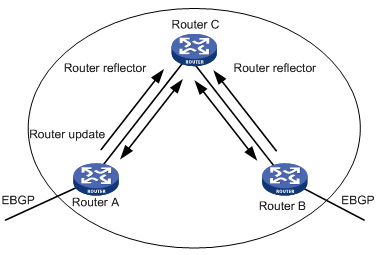
Figure 1-1 The route reflector diagram
In Figure 1-1, Router C is a route reflector with two peer clients: Router A and Router B. Router A sends to Router C the update packet from an external peer. Router C sends the update packet to Router B. After using reflecting technology, you do not need to establish a connection between Router A and Router B. You only need to connect Router C to Router A and Router B respectively.
If a BGP router is not either a reflector or client, we call the BGP router non-client. You still need connect non-clients to reflectors and non-clients.
You only need to configure route reflecting for the route reflector. When configuring the route reflector, you must specify the routers to serve as clients.
I. Configuring an IBGP peer group as route reflector client
Perform the following configuration in BGP view to specify an IBGP peer group to be/not to be a route reflector client:
|
To do... |
Use the command... |
|
Configure an IBGP peer group as route reflector client |
peer group-name reflect-client |
|
Disable an IBGP peer group from being a route reflector client |
undo peer group-name reflect-client |
This command works on IBGP peer groups only.
By default, all IBGP routes in an AS must be full-connected, and neighbors do not advertise learned IBGP routes to one another.
II. Configuring the route reflection between clients
Perform the following configuration in BGP view to enable/disable route reflection between clients:
|
To do... |
Use the command... |
|
Enable route reflection between clients |
reflect between-clients |
|
Disable route reflection between clients |
undo reflect between-clients |
By default, the route reflection between clients is allowed. If the clients are fully connected, for the purpose of overhead reduction, it is recommended to use the undo reflect between-clients command to disable the route reflection between clients.
III. Configuring the cluster ID
Generally, there is only one route reflector in a cluster which is identified by the router ID of the route reflector.
Perform the following configuration in BGP view to configure/cancel the Cluster_ID of the route reflector:
|
To do... |
Use the command... |
|
Configure the Cluster_ID of the route reflector |
reflector cluster-id { cluster-id | address } |
|
Cancel the Cluster_ID of the route reflector |
undo reflector cluster-id |
The autonomous system possibly generates routing loop due to the route reflector in a cluster. After leaving a cluster, a routing update packet possibly tries to go back to the cluster. Because the routing update packet has not left an AS, the traditional AS path method cannot detect the loop inside the AS. When configuring route reflectors, you can use the following two methods to avoid loop inside the AS. One is to use the cluster ID; the other is to use Originator_ID of a route reflector.
If you configure Originator_ID improperly, the originator will discard the update packet when the update packet goes back to the originator. You do not need to configure Originator_ID. Originator_ID automatically takes effect when BGP is enabled.
1.2.18 Configuring BGP AS Confederation Attribute
Confederation provides the method to handle the booming IBGP network connections inside AS. It divides the AS into multiple sub-AS, in each of which all IBGP peers are fully connected, and are connected with other sub-AS of the confederation.
The shortcomings of confederation are that it is required that the route be re-configured upon switching from non-confederation to confederation solution, and that the logic topology be basically changed. Furthermore, the path selected via confederation may not be the best path if there is no manually-set BGP policy.
I. Configuring confederation_ID
In the eye of the BGP speakers that are not included in the confederation, multiple sub-ASs that belong to the same confederation are a whole. The external network does not need to know the status of internal sub-ASs, and the confederation ID is the AS number identifying the confederation as a whole.
Perform the following configuration in BGP view to configure/cancel confederation_ID:
|
To do... |
Use the command... |
|
Configure confederation_ID |
confederation id as-number |
|
Cancel confederation_ID |
undo confederation id |
By default, the confederation_ID is not configured.
The configured confederation_ID and the existing AS number of a peer or peer group cannot be the same.
II. Configuring sub-AS belonging to the confederation
Configure confederation_ID first, and then configure the sub-AS belonging to the confederation. One confederation includes up to 32 sub-AS.
Perform the following configuration in BGP view to configure/cancel sub-AS belonging to the confederation:
|
To do... |
Use the command... |
|
Configure a confederation consisting of which sub-ASs |
confederation peer-as as-number-1 [ ... as-number-n ] |
|
Cancel the specified sub-AS in the confederation |
undo confederation peer-as [ as-number-1 ] [ ...as-number-n ] |
By default, no autonomous system is configured as a member of the confederation.
The configured sub-AS number is valid only inside the confederation. In addition, the number cannot be the same as the AS number of a peer in the peer group for which you have not configured an AS number.
III. Configuring AS confederation attribute compatible with nonstandard
If it is necessary to perform the interconnection with the devices whose implementation mechanism is different from that of RFC1965, you must configure all the routers in the confederation.
Perform the following configuration in BGP view to configure/cancel AS confederation attribute compatible with nonstandard:
|
To do... |
Use the command... |
|
Configure AS confederation attribute compatible with nonstandard router |
confederation nonstandard |
|
Cancel AS confederation attribute compatible with nonstandard router |
undo confederation nonstandard |
By default, the configured confederation is consistent with RFC1965.
1.2.19 Configuring BGP Load Balancing
As BGP is a routing protocol for route selection only, it does not provide a route calculation method. Therefore, it is not possible to determine whether to enable load balancing based on a definite metric value. However, the BGP owns a variety of route selection rules, so it supports conditional load balancing after route selection, namely, by adding load balancing into the BGP route selection rules.
With BGP load balancing enabled, during route selection, the BGP will add rule between the last two route selection rules “select routes learned from EBGP with preference” and “select routes advertised by the router with the lowest BGP ID”: if load balancing is enabled, and if there are multiple exterior routes to the same AS or AS confederation, the BGP will select multiple routes, depending on the number of routes, for load balancing. The BGP supports load balancing for routes learned from EBGP/IBGP under the following conditions:
l In case of routes learned from EBGP, the BGP performs load balancing for routes from the same AS and with the same med value only;
l In case of routes learned from IBGP, the BGP performs load balancing for routes with the same med value, local_pref, AS_PATH and origin attributes.
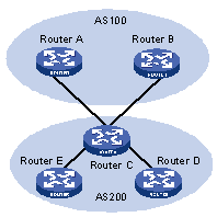
Figure 1-2 A schematic diagram of BGP load balancing
As shown in Figure 1-2, Router D and Router E are IBGP peers of Router C. When Router A and Router B simultaneously advertise two routes to the same destination to Router C, if Router C is load balancing enabled (such as balance 2), while satisfying a certain route selection rule, Router C will add both routes into the forwarding table if the two routes have the same AS_PATH attribute, so as to achieve the purpose of BGP route balancing. Router C forwards the routes to Router D and Router E only once. The AS_PATH attribute will remain unchanged, but the NEXT_HOP attribute will be changed to the address of Router C, instead of the address of the original EBGP peer. The BGP will directly transfer the other transient attributes as attributes of the optimal route.
The BGP balancing feature also applies to routing between ASs within an AS confederation.
& Note:
Load balancing is not available for BGP default routes.
Perform the following configuration in BGP view to enable/disable BGP load balancing:
|
To do... |
Use the command... |
|
Enable BGP load balancing |
balance balance-number |
|
Disable BGP load balancing |
undo balance |
By default, the BGP does not implement load balancing.
1.2.20 Setting the Switch for Adjacency State Output
When the switch for adjacency state output is enabled, the BGP adjacency state changes will be output to the configured terminal until the switch for adjacency state output is disabled.
Perform the following configuration in BGP view to set the switch for BGP adjacency state output:
|
To do... |
Use the command... |
Description |
|
Enter system view |
system-view |
— |
|
Enter BGP view |
bgp as-number |
Required |
|
Enable the switch for adjacency state output |
log-peer-change |
The BGP peer changes are not reported by default |
1.2.21 Clearing BGP Connection
After the user changes BGP policy or protocol configuration, they must cut off the current connection so as to enable the new configuration.
Perform the following configuration in user view to clear BGP connection:
|
To do... |
Use the command... |
|
Clear the connection between BGP and the specified peers |
reset bgp peer-address |
|
Clear all connections of BGP |
reset bgp all |
|
Clear the connections between the BGP and all the members of a group |
reset bgp group group-name |
1.2.22 Refreshing BGP Routes
It is required to re-compute associated route information when BGP route policy changes.
Perform the following configuration in user view to refresh BGP routes:
|
To do... |
Use the command... |
|
Refresh general BGP routes |
refresh bgp { all | peer-address | group group-name } [ multicast | vpn-instance instance-name | vpnv4 ] { import | export } |
1.3 Displaying and Debugging BGP
|
To do... |
Use the command... |
Remarks |
|
Display the routing information in BGP routing table |
display bgp routing-table [ ip-address [ mask ] ] |
Available in any view |
|
Display filtered AS path information in the BGP |
display ip as-path-acl [ acl-number ] |
|
|
Display CIDR routes |
display bgp routing-table cidr |
|
|
Display the routing information of the specified BGP community |
display bgp routing-table community [ aa:nn ]* [ no-export-subconfed | no-advertise | no-export ]* [ whole-match ] |
|
|
Display the routing information allowed by the specified BGP community list |
display bgp routing-table community-list community-list-number [ whole-match ] |
|
|
Display BGP dampened paths |
display bgp routing-table dampened |
|
|
Display the routing information the specified BGP peer advertised or received |
display bgp routing-table peer peer-address { advertised | received } [ network-address [ mask ] | statistic ] |
|
|
Display the total number or route entries received or advertised by all BGP peers |
display bgp routing-table [ advertised | received ] statistic |
|
|
Display the routes matching with the specified access-list |
display bgp routing-table as-path-acl acl-number |
|
|
Display route flapping statistics information |
display bgp routing-table flap-info [ regular-expression as-regular-expression | as-path-acl acl-number | network-address [ mask [ longer-match ] ] ] |
|
|
Display routes from different source ASs |
display bgp routing-table different-origin-as |
|
|
Display peers information |
display bgp peer [ peer-address ] [ verbose ] |
|
|
Display the configured routing information |
display bgp network |
|
|
Display AS path information |
display bgp paths as-regular-expression |
|
|
Display peer group information |
display bgp group [ group-name ] |
|
|
Display the AS path information matching the specified regular expression |
display bgp routing-table regular-expression as-regular-expression |
|
|
Display configured route-policy information |
display route-policy [ route-policy-name ] |
|
|
Enable/disable debugging of all BGP packets |
[ undo ] debugging bgp all |
Available in user view |
|
Enable/disable BGP event debugging |
[ undo ] debugging bgp event |
|
|
Enable/disable BGP Keepalive debugging |
[ undo ] debugging bgp keepalive [ receive | send ] [ verbose ] |
|
|
Enable/Disable BGP Open debugging |
[ undo ] debugging bgp open [ receive | send ] [ verbose ] |
|
|
Enable /Disable BGP packet debugging |
[ undo ] debugging bgp packet [ receive | send ] [ verbose ] |
|
|
Enable/disable BGP Route-Refresh packet debugging |
[ undo ] debugging bgp route-refresh [ receive | send ] [ verbose ] |
|
|
Enable/Disable information debugging of BGP normal functions. |
[ undo ] debugging bgp normal |
|
|
Enable/disable BGP Update packet debugging |
[ undo ] debugging bgp update [ receive | send ] [ verbose ] |
|
|
Reset BGP flapping statistics information |
reset bgp flap-info [ regular-expression as-regular-expression | as-path-acl acl-number | network-address [ mask ] ] |
1.4 BGP Configuration Examples
1.4.1 Configuring BGP AS Confederation Attribute
I. Network requirements
Divide the following AS 100 into three sub-AS: 1001, 1002, and 1003, and configure EBGP, confederation EBGP, and IBGP.
II. Network diagram
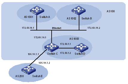
Figure 1-3 Network diagram for AS confederation configuration
III. Configuration procedure
# Configure Switch A.
[Switch A] bgp 1001
[Switch A-bgp] confederation id 100
[Switch A-bgp] confederation peer-as 1002 1003
[Switch A-bgp] group confed1002 external
[Switch A-bgp] peer confed1002 as-number 1002
[Switch A-bgp] group confed1003 external
[Switch A-bgp] peer confed1003 as-number 1003
[Switch A-bgp] peer 172.68.10.2 group confed1002
[Switch A-bgp] peer 172.68.10.3 group confed1003
# Configure Switch B.
[Switch B] bgp 1002
[Switch B-bgp] confederation id 100
[Switch B-bgp] confederation peer-as 1001 1003
[Switch B-bgp] group confed1001 external
[Switch B-bgp] peer confed1001 as-number 1001
[Switch B-bgp] group confed1003 external
[Switch B-bgp] peer confed1003 as-number 1003
[Switch B-bgp] peer 172.68.10.1 group confed1001
[Switch B-bgp] peer 172.68.10.3 group confed1003
# Configure Switch C.
[Switch C] bgp 1003
[Switch C-bgp] confederation id 100
[Switch C-bgp] confederation peer-as 1001 1002
[Switch C-bgp] group confed1001 external
[Switch C-bgp] peer confed1001 as-number 1001
[Switch C-bgp] group confed1002 external
[Switch C-bgp] peer confed1002 as-number 1002
[Switch C-bgp] peer 172.68.10.1 group confed1001
[Switch C-bgp] peer 172.68.10.2 group confed1002
[Switch C-bgp] group ebgp200 external
[Switch C-bgp] peer 156.10.1.2 group ebgp200 as-number 200
[Switch C-bgp] group ibgp1003 internal
[Switch C-bgp] peer 172.68.1.2 group ibgp1003
1.4.2 Configuring BGP Route Reflector
I. Network requirements
Switch B receives an update packet passing EBGP and transmits it to Switch C. Switch C is a reflector with two clients: Switch B and Switch D. When Switch C receives a route update from Switch B, it will transmit such information to Switch D. It is required to establish an IBGP connection between Switch B and Switch D, because Switch C reflects information to Switch D.
II. Network diagram

Figure 1-4 Network diagram for BGP route reflector configuration
III. Configuration procedure
1) Configure Switch A.
[Switch A] interface vlan-interface 2
[Switch A-Vlan-interface2] ip address 192.1.1.1 255.255.255.0
[Switch A-Vlan-interface2] interface Vlan-interface 100
[Switch A-Vlan-interface100] ip address 1.1.1.1 255.0.0.0
[Switch A-Vlan-interface100] quit
[Switch A] bgp 100
[Switch A-bgp] network 1.0.0.0 255.0.0.0
[Switch A-bgp] group ex external
[Switch A-bgp] peer 192.1.1.2 group ex as-number 200
2) Configure Switch B.
# Configure VLAN 2.
[Switch B] interface Vlan-interface 2
[Switch B-Vlan-interface2] ip address 192.1.1.2 255.255.255.0
# Configure VLAN 3.
[Switch B] interface Vlan-interface 3
[Switch B-Vlan-interface3] ip address 193.1.1.2 255.255.255.0
# Configure BGP peers.
[Switch B] bgp 200
[Switch B-bgp] group ex external
[Switch B-bgp] peer 192.1.1.1 group ex as-number 100
[Switch B-bgp] group in internal
[Switch B-bgp] peer 193.1.1.1 group in
3) Configure Switch C.
# Configure VLAN 3.
[Switch C] interface Vlan-interface 3
[Switch C-Vlan-interface3] ip address 193.1.1.1 255.255.255.0
# Configure VLAN 4.
[Switch C] interface vlan-Interface 4
[Switch C-Vlan-interface4] ip address 194.1.1.1 255.255.255.0
# Configure BGP peers and route reflector.
[Switch C] bgp 200
[Switch C-bgp] group rr internal
[Switch C-bgp] peer rr reflect-client
[Switch C-bgp] peer 193.1.1.2 group rr
[Switch C-bgp] peer 194.1.1.2 group rr
4) Configure Switch D.
# Configure VLAN 4:
[Switch D] interface vlan-interface 4
[Switch D-Vlan-interface4] ip address 194.1.1.2 255.255.255.0
# Configure BGP peers.
[Switch D] bgp 200
group in internal
[Switch D-bgp] peer 194.1.1.1 group in
Using the display bgp routing-table command, you can view BGP routing table on Switch B. Note: Switch B has known the existence of network 1.0.0.0.
Using the display bgp routing-table command, you can view the BGP routing table on Switch D. Note: Switch D also knows the existence of network 1.0.0.0.
1.4.3 Configuring BGP Routing
I. Network requirements
This example illustrates how the administrators manage the routing via BGP attributes. All switches are configured with BGP, and IGP in AS 200 utilizes OSPF. Switch A is in AS 100, and Switch B, Switch C and Switch D are in AS 200. Switch A, Switch B, and Switch C operate EBGP. Switch B, Switch C and Switch D operate IBGP.
II. Network diagram
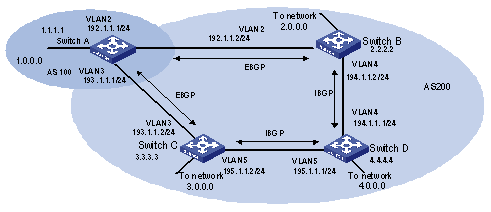
Figure 1-5 Networking diagram for BGP routing configuration
III. Configuration procedure
1) Configure Switch A.
[Switch A] interface Vlan-interface 2
[Switch A-Vlan-interface2] ip address 192.1.1.1 255.255.255.0
[Switch A] interface Vlan-interface 3
[Switch A-Vlan-interface3] ip address 193.1.1.1 255.255.255.0
# Enable BGP.
[Switch A] bgp 100
# Specify the network that BGP sends to.
[Switch A-bgp] network 1.0.0.0
# Configure the peers
[Switch A-bgp] group ex192 external
[Switch A-bgp] peer 192.1.1.2 group ex192 as-number 200
[Switch A-bgp] group ex193 external
[Switch A-bgp] peer 193.1.1.2 group ex193 as-number 200
[Switch A-bgp] quit
# Configure the MED attribute of Switch A.
Add ACL on Switch A and permit network 1.0.0.0.
[Switch A] acl number 2000
[Switch A-acl-basic-2000] rule permit source 1.0.0.0 0.255.255.255
[Switch A-acl-basic-2000] rule deny source any
Define two route policies, one is called Apply_med_50 and the other is called Apply_med_100. The first MED attribute with the route policy as network 1.0.0.0 is set as 50, while the MED attribute of the second is 100.
[Switch A] route-policy apply_med_50 permit node 10
[Switch A-route-policy] if-match acl 2000
[Switch A-route-policy] apply cost 50
[Switch A-route-policy] quit
[Switch A] route-policy apply_med_100 permit node 10
[Switch A-route-policy] if-match acl 2000
[Switch A-route-policy] apply cost 100
[Switch A-route-policy] quit
Apply route policy Apply_med_50 to egress route update of Switch C (193.1.1.2), and apply route policy Apply_med_100 on the egress route of Switch B (192.1.1.2)
[Switch A] bgp 100
[Switch A-bgp] peer ex193 route-policy apply_med_50 export
[Switch A-bgp] peer ex192 route-policy apply_med_100 export
2) Configure Switch B:
[Switch B] interface vlan-interface 2
[Switch B-Vlan-interface2] ip address 192.1.1.2 255.255.255.0
[Switch B] interface vlan-interface 4
[Switch B-Vlan-interface4] ip address 194.1.1.2 255.255.255.0
[Switch B] ospf
[Switch B-ospf-1] area 0
[Switch B-ospf-1-area-0.0.0.0] network 194.1.1.0 0.0.0.255
[Switch B-ospf-1-area-0.0.0.0] network 192.1.1.0 0.0.0.255
[Switch B] bgp 200
[Switch B-bgp] group ex external
[Switch B-bgp] peer 192.1.1.1 group ex as-number 100
[Switch B-bgp] group in internal
[Switch B-bgp] peer 194.1.1.1 group in
[Switch B-bgp] peer 195.1.1.2 group in
3) Configure Switch C:
[Switch C] interface Vlan-interface 3
[Switch C-Vlan-interface3] ip address 193.1.1.2 255.255.255.0
[Switch C] interface vlan-interface 5
[Switch C-Vlan-interface5] ip address 195.1.1.2 255.255.255.0
[Switch C] ospf
[Switch C-ospf-1] area 0
[Switch C-ospf-1-area-0.0.0.0] network 193.1.1.0 0.0.0.255
[Switch C-ospf-1-area-0.0.0.0] network 195.1.1.0 0.0.0.255
[Switch C] bgp 200
[Switch C-bgp] group ex external
[Switch C-bgp] peer 193.1.1.1 group ex as-number 100
[Switch C-bgp] group in internal
[Switch C-bgp] peer 195.1.1.1 group in
[Switch C-bgp] peer 194.1.1.2 group in
4) Configure Switch D.
[Switch D] interface vlan-interface 4
[Switch D-Vlan-interface4] ip address 194.1.1.1 255.255.255.0
[Switch D] interface vlan-interface 5
[Switch D-Vlan-interface5] ip address 195.1.1.1 255.255.255.0
[Switch D] ospf
[Switch D-ospf-1] area 0
[Switch D-ospf-1-area-0.0.0.0] network 194.1.1.0 0.0.0.255
[Switch D-ospf-1-area-0.0.0.0] network 195.1.1.0 0.0.0.255
[Switch D-ospf-1-area-0.0.0.0] network 4.0.0.0 0.255.255.255
[Switch D] bgp 200
[Switch D-bgp] group ex external
[Switch D-bgp] peer ex as-number 200
[Switch D-bgp] peer 195.1.1.2 group ex
[Switch D-bgp] peer 194.1.1.2 group ex
To enable the configuration, all BGP neighbors will be reset using the reset bgp all command.
After above configuration, due to the fact that the MED attribute of route 1.0.0.0 discovered by Switch C is less than that of Switch B, Switch D will first select the route 1.0.0.0 from Switch C.
If the MED attribute of Switch A is not configured, the local preference on Switch C is configured as follows:
# Configure the local preference attribute of Switch C.
l Add ACL 2000 on Switch C and permit network 1.0.0.0.
[Switch C] acl number 2000
[Switch C-acl-basic-2000] rule permit source 1.0.0.0 0.255.255.255
[Switch C-acl-basic-2000] rule deny source any
Define a route policy named Localpref, and set the local preference of routes matching ACL 2000 to 200, and that of routes not matching to 100.
[Switch C] route-policy localpref permit node 10
[Switch C-route-policy] if-match acl 2000
[Switch C-route-policy] apply local-preference 200
[Switch C-route-policy] route-policy localpref permit node 20
[Switch C-route-policy] apply local-preference 100
[Switch C-route-policy] quit
Apply this route policy to ingress traffic from BGP neighbor 193.1.1.1 (Switch A).
[Switch C] bgp 200
[Switch C-bgp] peer 193.1.1.1 route-policy localpref import
By then, due to the fact that the Local preference attribute value (200) of the route 1.0.0.0 learned by Switch C is higher than that of Switch B (Switch B is not configured with local Preference attribute, 100 by default), Switch D will also first select the route 1.0.0.0 from Switch C.
1.5 Troubleshooting BGP
Symptom 1: The neighbor relationship cannot be established (The Established state cannot be entered).
Solution: The establishment of BGP neighborhood needs the router able to establish TCP connection through port 179 and exchange Open packets correctly. Perform the check according to the following steps:
l Check whether the configuration of the neighbor's AS number is correct.
l Check whether the neighbor's IP address is correct.
l If it is the EBGP neighbor not directly connected, check whether the peer ebgp-max-hop command has been configured.
l Use the ping command to check whether the TCP connection is normal. Since one router may have several interfaces able to reach the peer, the extended ping -a ip-address command should be used to specify the source IP address sending ping packet.
l If the Ping operation fails, use the display ip routing-table command to check if there is available route in the routing table to the neighbor.
l If the Ping operation succeeds, check if there is an ACL denying TCP port 179. If the ACL is configured, cancel the denying of port 179.
Symptom 2: BGP route cannot be advertised correctly after route of IGP is imported with the network command.
Solution: Route imported by the network command should be same as a route in the current routing table, which should include destination segment and mask. Route covering large network segment cannot be imported. For example, route 10.1.1.0/24 can be imported, while 10.0.0.0/8 may cause error. If Ospf is used, after a large network segment is imported to the local route by means of the network command, the router will automatically make changes according to the network segment actually used by the interface. Consequently, the network command will fail to, or incorrectly, import routes, which can cause routing errors when some network faults exist.