- Table of Contents
-
- H3C S9500 Operation Manual-Release1648[v1.24]-03 IP Routing Volume
- 00-1Cover
- 01-IP Routing Protocol Overview
- 02-Static Route Configuration
- 03-RIP Configuration
- 04-OSPF Configuration
- 05-ISIS Configuration
- 06-BGP Configuration
- 07-IP Route Policy Configuration
- 08-Route Capacity Configuration
- 09-Recursive Routing Configuration
- Related Documents
-
| Title | Size | Download |
|---|---|---|
| 03-RIP Configuration | 98.42 KB |
Table of Contents
1.1.2 RIP Enabling and Running
1.2.1 Enabling RIP and Entering RIP View
1.2.2 Enabling RIP on the Specified Network Segment
1.2.3 Specifying a RIP Neighbor
1.2.4 Configuring Split Horizon
1.2.5 Setting Additional Routing Metric
1.2.6 Configuring RIP to Redistribute Routes from Other Protocols
1.2.7 Configuring Route Filtering
1.2.8 Disabling RIP from Receiving Host Route
1.2.9 Configuring RIP-2 Route Summary Function
1.2.10 Setting the RIP Preference
1.2.11 Specifying RIP Version of the Interface
1.2.13 Configuring RIP-1 Zero Field Check of the Interface Packet
1.2.14 Specifying the Operating State of the Interface
1.2.15 Setting RIP-2 Packet Authentication
1.3 Displaying and Debugging RIP
Chapter 1 RIP Configuration
When configuring RIP, go to these sections for information you are interested in:
l Displaying and Debugging RIP
& Note:
l The term “router” or the router icon in this document refers to a router in a generic sense or an S9500 switch running routing protocols.
l For details about VPN instance, refer to the MPLS VPN Volume.
1.1 Introduction to RIP
Routing Information Protocol (RIP) is a relatively simple interior gateway protocol (IGP), which is mainly applied to small-scale networks.
It is easy to implement RIP. You can configure and maintain RIP more easily than OSPF and IS-IS. Therefore, RIP still has a wide application in actual networking.
1.1.1 RIP Operation Mechanism
I. RIP basic concepts
RIP is a Distance-Vector (D-V) algorithm-based protocol and exchanges routing information via UDP packets.
It employs Hop Count to measure the distance to the destination host, which is called routing cost. In RIP, the hop count from a router to its directly connected network is 0, and that to a network which can be reached through another router is 1, and so on. To restrict the time to converge, RIP prescribes that the cost value is an integer ranging from 0 to 15. The hop count equal to or exceeding 16 is defined as infinite, that is, the destination network or the host is unreachable.
To improve the performance and avoid routing loops, RIP supports Split Horizon and allows importing the routes discovered by other routing protocols.
II. RIP route database
Each router running RIP manages a route database, which contains routing entries to all the reachable destinations in the network. These routing entries contain the following information:
l Destination address: IP address of a host or a network.
l Next hop address: The interface address of the next router that an IP packet will pass through for reaching the destination.
l Output interface: The interface through which the IP packet should be forwarded.
l Cost: The cost for the router to reach the destination, which should be an integer in the range of 0 to 16.
l Timer: Duration from the last time that the routing entry is modified till now. The timer is reset to 0 whenever a routing entry is modified.
III. RIP timer
According to RFC1058, RIP is controlled by the following timers: Period update, Timeout and Garbage-Collection.
l Period Update is triggered periodically to send all RIP routes to all neighbors.
l If no RIP route is updated (a router receives the update packets from the neighbor) within the Timeout timer, this route is regarded as unreachable. The cost is set to 16.
l If the Garbage-Collection timer expires, and the unreachable route receives no update packet from the same neighbor, the route will be completely deleted from the routing table.
l By default, the values of Period Update and Timeout timers are 30 seconds and 180 seconds respectively. The value of Garbage-collection timer is four times that of Period Update timer: 120 seconds.
1.1.2 RIP Enabling and Running
The following section describes the procedure:
l If RIP is enabled on a router for the first time, the router will broadcast or multicast the request packet to the adjacent routers. Upon receiving the request packet, the RIP on each adjacent router responds with a packet conveying its local routing table.
l After receiving the response packets, the router, which has sent the request, will modify its own routing table. At the same time, the router sends trigger modification packets to its adjacent routers running RIP and broadcasts modification information, following split horizon mechanism. After receiving trigger modification packets, the adjacent routers send trigger modification packets to their respective adjacent routers. As a result, each router can obtain and maintain the latest routing information.
l RIP broadcasts its routing table to the adjacent routers every 30 seconds. The adjacent routers will maintain their own routing table after receiving the packets and will select an optimal route, and then advertise the modification information to their respective adjacent network so as to make the updated route globally known. Furthermore, RIP uses the timeout mechanism to handle the routes that timed out so as to ensure the real-timeliness and validity of the routes.
RIP has become one of the actual standards of transmitting router and host routes by far. It can be used in most of the campus networks and the regional networks that are simple yet extensive. For larger and more complicated networks, RIP is not recommended.
1.2 Configuring RIP
1) RIP basic configuration
RIP basic configuration includes:
l Enabling RIP and Entering RIP View
l Enabling RIP on the Specified Network Segment
If the link, which does not support broadcast or multicast packets, runs RIP, you need to configure RIP to send any packet to the specified destination, establishing RIP neighbors correctly.
In NBMA link networking through a Frame Relay sub-interface and others, to ensure the routing information can be correctly transmitted, you possibly need to disable split horizon.
2) RIP route management
You can make the following configurations for RIP to advertise and receive routing information:
l Setting Additional Routing Metric
l Configuring RIP to Redistribute Routes from Other Protocols
l Disabling RIP from Receiving Host Route
l Configuring RIP-2 Route Summary Function
3) RIP configuration
l Specifying RIP Version of the Interface
l Configuring RIP-1 Zero Field Check of the Interface Packet
4) Configuration related to security
You can select the following configurations to improve RIP security during exchanging routing information, or control the area to transmit RIP packets.
l Specifying the Operating State of the Interface
l Setting RIP-2 Packet Authentication
1.2.1 Enabling RIP and Entering RIP View
Perform the following configurations in system view to enable/disable RIP:
|
To do… |
Use the command... |
|
Enable RIP and enter the RIP view |
rip |
|
Disable RIP |
undo rip |
By default, RIP is not enabled.
1.2.2 Enabling RIP on the Specified Network Segment
To flexibly control RIP operation, you can enable RIP on the specified network segment so that the corresponding interface can receive and send RIP packets.
Perform the following configurations in RIP view to enable/disable RIP:
|
To do... |
Use the command... |
|
Enable RIP on the specified network |
network network-address |
|
Disable RIP on the specified network |
undo network network-address |
Note that after the RIP task is enabled, you should also specify its operating network segment, for RIP only operates on the interface on the specified network segment. For an interface that is not on the specified network segment, RIP does not receive or send routes on it, nor forwards its interface route, as if this interface does not exist at all. network-address is the address of the enabled or disabled network, and it can also be configured as the IP network address of respective interfaces.
When the network command is used for an address, you can enable the network address of the port, which also includes the subnet addresses. For example, for network 129.102.1.1, you can see network 129.102.0.0 either using the display current-configuration command or the display rip command.
By default, RIP is disabled on all the interfaces after it is started up.
1.2.3 Specifying a RIP Neighbor
Usually, RIP sends packets to broadcast or multicast addresses. It exchanges routing information with a neighbor on a non-broadcast network in unicast mode. In this case, you need to specify the IP address of the neighbor.
Perform the following configuration in RIP view to specify/remove a unicast address for the packets:
|
To do... |
Use the command... |
|
Specify the RIP neighbor |
peer ip-address |
|
Remove the RIP neighbor |
undo peer ip-address |
By default, RIP does not send any packets to any unicast addresses.
It should be noted that a peer should also be restricted by rip work, rip output, rip input and network when transmitting packets.
1.2.4 Configuring Split Horizon
Split horizon means that the route received via an interface will not be sent via this interface again. To some extent, the split horizon is necessary for reducing routing loops. But in some special cases, split horizon must be disabled to ensure the correct advertisement of the routes at the cost of efficiency. For example, split horizon is disabled on an NBMA network if it runs RIP.
Perform the following configuration in interface view to enable/disable Split Horizon:
|
To do… |
Use the command... |
|
Enable split horizon |
rip split-horizon |
|
Disable split horizon |
undo rip split-horizon |
By default, split horizon of the interface is enabled.
1.2.5 Setting Additional Routing Metric
Additional routing metric is the input or output routing metric added to an RIP route. It does not change the metric value of the route in the routing table, but adds a specified metric value when the interface receives or sends a route.
Perform the following configuration in interface view to set/disable additional routing metric:
|
To do... |
Use the command... |
|
Set the additional routing metric of the route when the interface receives an RIP packet |
rip metricin value |
|
Disable the additional routing metric of the route when the interface receives an RIP packet |
undo rip metricin |
|
Set the additional routing metric of the route when the interface sends an RIP packet |
rip metricout value |
|
Disable the additional routing metric of the route when the interface sends an RIP packet |
undo rip metricout |
By default, the additional routing metric added to the route when RIP sends a packet is 1. The additional routing metric when RIP receives the packet is 0 by default.
& Note:
The metricout configuration takes effect only on the RIP routes learned by the router and RIP routes generated by the router itself. That is, it has no effect on the routes imported to RIP by other routing protocols.
1.2.6 Configuring RIP to Redistribute Routes from Other Protocols
You can redistribute route information from other protocols into the RIP routing table.
These routing protocols include: direct, Static, OSPF, OSPF-ASE, OSPF-NSSA, IS-IS, NAT, and BGP. When configuring route redistribution from BGP, you can specify the allow-ibgp keyword to redistribute IBGP routes.
Perform the following configuration in RIP view to configure RIP to/not to import routes of other protocols:
|
To do... |
Use the command... |
|
Configure RIP to import routes of other protocols |
import-route protocol [ cost value | route-policy route-policy-name ]* |
|
Cancel the imported routing information of other protocols |
undo import-route protocol |
|
Set the default routing metric |
default cost value |
|
Restore the default routing metric |
undo default cost |
By default, RIP does not import the route information of other protocols.
If you do not specify the routing metric when importing a route, the default routing metric 1 is used.
1.2.7 Configuring Route Filtering
The router provides the route filtering function. You can configure the filter policy rules through specifying the ACL and IP-prefix for route import and advertisement. Besides, to import a route, the RIP packet of a specific router can also be received by designating a neighbor router.
Perform the following configuration in RIP view.
I. Configuring RIP to filter the received routes
Follow these steps to configure RIP to/not to filter the received routes:
|
To do... |
Use the command... |
|
Configure RIP to filter the received routing information advertised by the specified address |
filter-policy gateway ip-prefix-name import |
|
Cancel filtering the received routing information advertised by the specified address |
undo filter-policy gateway ip-prefix-name import |
|
Configure RIP to filter the received global routing information |
filter-policy { acl-number | ip-prefix ip-prefix-name } import |
|
Cancel filtering the received global routing information |
undo filter-policy { acl-number | ip-prefix ip-prefix-name } import |
II. Configuring RIP to filter the routes advertised by RIP
Follow these steps to configure RIP to/not to filter the advertised routes:
|
To do... |
Use the command... |
|
Configure RIP to filter the advertised routing information |
filter-policy { acl-number | ip-prefix ip-prefix-name } export [ routing-protocol ] |
|
Cancel filtering the advertised routing information |
undo filter-policy { acl-number | ip-prefix ip-prefix-name } export [ routing-protocol ] |
By default, RIP does not filter the received and advertised routing information.
& Note:
l The filter-policy import command filters the RIP routes received from its neighbors, and the routes that fail to pass the filter will not be added to the routing table, and will not be advertised to the neighbors.
l The filter-policy export command filters all the advertised routes, including routes imported by the import-route command, and RIP routes learned from the neighbors.
l If the filter-policy export command does not specify which route to be filtered, then all the routes imported by the import-route command and the advertised RIP routes will be filtered.
l If no rule is specified in the filter-policy command, all routes are denied by default.
1.2.8 Disabling RIP from Receiving Host Route
In some special cases, the router can receive a lot of host routes, and these routes are of little help in routing but consume a lot of network resources. Routers can be configured to reject host routes with the undo host-route command.
Perform the following configuration in RIP view to enable/disable host route receiving:
|
To do... |
Use the command... |
|
Enable the route to receive host route |
host-route |
|
Disable the router from receiving host route |
undo host-route |
By default, the router receives the host route.
1.2.9 Configuring RIP-2 Route Summary Function
Route summary means that different subnet routes in the same natural network can be aggregated into one natural mask route for transmission when they are sent outside (that is, another network). Route summary can be performed to reduce the routing traffic on the network as well as to reduce the size of the routing table.
RIP-1 only sends the route with natural mask, that is, it always sends routes in the route summary form. RIP-2 supports subnet mask and classless inter-domain routing. To advertise all the subnet routes, the route summary function of RIP-2 can be disabled.
Perform the following configuration in RIP view to enable/disable RIP-2 route summary function:
|
To do... |
Use the command... |
|
Enable the route summary function of RIP-2 |
summary |
|
Disable the route summary function of RIP-2 |
undo summary |
By default, RIP-2 route summary is enabled.
1.2.10 Setting the RIP Preference
Each routing protocol has its own preference, by which the route policy will select the optimal one from the routes of different protocols. The greater the preference value is, the lower the preference becomes. The preference of RIP can be set manually.
Perform the following configuration in RIP view to set/restore the RIP preference:
|
To do… |
Use the command... |
|
Set the RIP Preference |
preference value |
|
Restore the default value of RIP preference |
undo preference |
By default, the preference of RIP is 100.
1.2.11 Specifying RIP Version of the Interface
RIP has two versions: RIP-1 and RIP-2. You can specify the version of the RIP packets processed by the interface.
RIP-1 broadcasts the packets. RIP-2 can broadcast or multicast packets. By default, multicast is adopted for transmitting packets. In RIP-2, the multicast address is 224.0.0.9. The advantage of transmitting packets in the multicast mode is that the hosts not running RIP in the same network can avoid receiving RIP broadcast packets. In addition, this mode can also make the hosts running RIP-1 avoid incorrectly receiving or processing the routes with subnet mask in RIP-2. When an interface is running in RIP-2 broadcast mode, the RIP-1 packets can also be received.
Perform the following configuration in interface view to specify/restore RIP version of the interface:
|
To do... |
Use the command... |
|
Specify the RIP version as RIP-1 for the interface |
rip version 1 |
|
Specify the RIP version as RIP-2 for the interface |
rip version 2 [ broadcast | multicast ] |
|
Restore the default RIP version running on the interface |
undo rip version |
By default, the interface receives and sends the RIP-1 packets. It will transmit packets in multicast mode when the interface RIP version is set to RIP-2.
1.2.12 Configuring RIP Timers
As mentioned previously, RIP has three timers: Period update, Timeout and Garbage-collection. Modification of these timers affects RIP convergence speed.
Perform the following configuration in RIP view to configure/restore RIP timers:
|
To do... |
Use the command... |
|
Configure RIP timers |
timers { update update-timer-length | timeout timeout-timer-length } * |
|
Restore the default settings of RIP timers |
undo timers { update | timeout } * |
The modification of RIP timers is validated immediately.
By default, the values of Period Update and Timeout timers are 30 seconds and 180 seconds respectively. The value of Garbage-collection timer is four times that of Period Update timer: 120 seconds.
In fact, you may find that the timeout time of Garbage-collection timer is not fixed. If Period Update timer is set to 30 seconds, Garbage-collection timer might range from 90 to 120 seconds.
Before RIP completely deletes an unreachable route from the routing table, it advertises the route by sending four Period Update packets with a route metric of 16, so as to acknowledge all the neighbors to which the route is unreachable. As routes cannot always become unreachable at the point when a new period starts, the actual value of Garbage-collection timer is three to four times that of Period Update timer.
& Note:
You must consider network performance when adjusting RIP timers, and configure all the routers that are running RIP, so as to avoid unnecessary traffic or network jitter.
1.2.13 Configuring RIP-1 Zero Field Check of the Interface Packet
According to the RFC1058, some fields in the RIP-1 packet must be 0, and they are called zero fields. Therefore, when an interface version is set as RIP-1, the zero field check should be performed on the packet. But if the value in the zero filed is not zero, processing will be refused. As there is no zero field in the RIP-2 packet, this configuration is invalid for RIP-2.
Perform the following configuration in RIP view to configure/disable zero field check of the interface packet:
|
To do... |
Use the command... |
|
Configure zero field check on the RIP-1 packet |
checkzero |
|
Disable zero field check on the RIP-1 packet |
undo checkzero |
By default, RIP-1 performs zero field check on the packet.
1.2.14 Specifying the Operating State of the Interface
In interface view, you can specify the operating state of RIP on the interface. For example, whether RIP operates on the interface, namely, whether RIP update packets are sent and received on the interface. In addition, whether an interface sends or receives RIP update packets can be specified separately.
Perform the following configuration in interface view to specify the operating state of the interface:
|
To do... |
Use the command... |
|
Enable the interface to run RIP |
rip work |
|
Disable the interface from running RIP |
undo rip work |
|
Enable the interface to receive RIP update packet |
rip input |
|
Disable the interface from receiving RIP update packets |
undo rip input |
|
Enable the interface to send RIP update packet |
rip output |
|
Disable the interface from sending RIP update packet |
undo rip output |
The undo rip work command and the undo network command have similar but not all the same functions. Neither of the two commands configures an interface to receive or send RIP route. The difference also exists. RIP still advertises the routes of the interface applying the undo rip work command. However, other interfaces will not forward the routes of the interface applying the undo network command. It seems that the interface is removed.
In addition, the rip work command is functionally equivalent to both the rip input command and the rip output command.
By default, all interfaces, except loopback interfaces, receive and transmit RIP update packets.
1.2.15 Setting RIP-2 Packet Authentication
RIP-1 does not support packet authentication. But when the interface runs RIP-2, the packet authentication can be configured.
RIP-2 supports two authentication modes: Simple authentication and MD5 authentication. MD5 authentication uses two packet formats: One follows RFC1723 and the other follows the RFC2082.
The simple authentication does not ensure security. The authentication key not encrypted is sent together with the packet, so the simple authentication cannot be applied to the cases with high security requirements.
Perform the following configuration in Interface view to set/disable RIP-2 packet authentication:
|
To do... |
Use the command... |
|
Configure RIP-2 simple authentication key |
rip authentication-mode simple password-string |
|
Perform usual MD5 authentication on RIP-2 packets |
rip authentication-mode md5 usual key-string |
|
Perform nonstandard-compatible MD5 authentication on RIP-2 packets |
rip authentication-mode md5 nonstandard key-string key-id |
|
Disable RIP-2 packet authentication |
undo rip authentication-mode |
Before configuring MD5 authentication, you must configure the MD5 type. The usual packet format follows RFC1723 and the nonstandard follows RFC2082.
1.3 Displaying and Debugging RIP
|
To do... |
Use the command... |
Remarks |
|
Display the current RIP running state and configuration information. |
display rip |
Available in any view |
|
Enable the RIP packet debugging information |
debugging rip packet |
Available in user view |
|
Disable the RIP packet debugging information |
undo debugging rip packet |
Available in user view |
|
Enable the debugging of RIP receiving packets |
debugging rip receive |
Available in user view |
|
Disable the debugging of RIP receiving packets |
undo debugging rip receive |
Available in user view |
|
Enable the debugging of RIP sending packet |
debugging rip send |
Available in user view |
|
Disable the debugging of RIP sending packet |
undo debugging rip send |
Available in user view |
|
Reset the system configuration parameters of RIP |
reset |
Available in RIP view |
1.4 RIP Configuration Example
I. Network requirements
As shown in Figure 1-1, the S9500 series routing switch C connects to the subnet 117.102.0.0 through the Ethernet port. The Ethernet ports of the S9500 series routing switches A and Switch B are respectively connected to the network 155.10.1.0 and 196.38.165.0. Switch C, Switch A and Switch B are connected via Ethernet 110.11.2.0. Correctly configure RIP to ensure that Switch C, Switch A and Switch B can interconnect with each other.
II. Network diagram
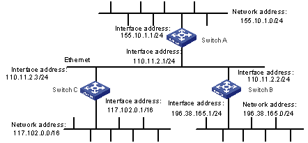
Figure 1-1 Network diagram for RIP configuration
III. Configuration procedure
& Note:
The following configuration only shows the operations related to RIP. Before performing the following configuration, make sure the Ethernet link layer can work normally.
1) Configure Switch A.
# Configure RIP.
[Switch A] rip
[Switch A-rip] network 110.11.2.0
[Switch A-rip] network 155.10.1.0
2) Configure Switch B.
# Configure RIP.
[Switch B] rip
[Switch B-rip] network 196.38.165.0
[Switch B-rip] network 110.11.2.0
3) Configure Switch C.
# Configure RIP.
[Switch C] rip
[Switch C-rip] network 117.102.0.0
[Switch C-rip] network 110.11.2.0
1.5 Troubleshooting RIP
Symptom: The S9500 series cannot receive the update packets when the physical connection to the peer routing device is normal.
Solution: RIP is not running on the corresponding interface (for example, the undo rip work command is executed) or this interface is not enabled through the network command. The peer routing device is configured to be in the multicast mode (for example, the rip version 2 multicast command is executed) but the multicast mode has not been configured on the corresponding interface of the local switch.