- Table of Contents
-
- H3C S9500 Operation Manual-Release1648[v1.24]-03 IP Routing Volume
- 00-1Cover
- 01-IP Routing Protocol Overview
- 02-Static Route Configuration
- 03-RIP Configuration
- 04-OSPF Configuration
- 05-ISIS Configuration
- 06-BGP Configuration
- 07-IP Route Policy Configuration
- 08-Route Capacity Configuration
- 09-Recursive Routing Configuration
- Related Documents
-
| Title | Size | Download |
|---|---|---|
| 01-IP Routing Protocol Overview | 170.33 KB |
Table of Contents
Chapter 1 IP Routing Protocol Overview
1.1 Introduction to IP Route and Routing Table
1.1.1 IP Route and Route Segment
1.1.2 Route Selection through the Routing Table
1.2.1 Routing Protocols and the Preferences of the Corresponding Routes
1.2.2 Supporting Load Sharing and Route Backup
1.2.3 Routes Shared Between Routing Protocols
Chapter 1 IP Routing Protocol Overview
Go to these sections for information you are interested in:
l Introduction to IP Route and Routing Table
& Note:
The term “router” or the router icon in this document refers to a router in a generic sense or an S9500 switch running routing protocols.
1.1 Introduction to IP Route and Routing Table
1.1.1 IP Route and Route Segment
Routers are used for route selection in the Internet. A router works in the following way: The router selects an appropriate path (through a network) according to the destination address of the packet it receives and forwards the packet to the next router. The last router in the path is responsible for submitting the packet to the destination host.
In Figure 1-1, R stands for a router. A packet sent from Host A to Host C should go through two routers and the packet is transmitted through two hops. Therefore, when a node (router) is connected to another node through a network, they are in the same route segment and are deemed as adjacent in the Internet. That is, the adjacent routers refer to two routers connected to the same network. The number of route segments between a router and hosts in the same network counted as zero. In Figure 1-1, the bold arrows represent these route segments. Which physical links comprise which route segment is not a concern of a router.
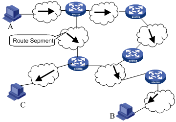
Figure 1-1 The concept of route segment
As the networks may have different sizes, the segment lengths connected between two different pairs of routers are also different. The number of route segments multiplies a weighted coefficient can serve as a weighted measurement for the actual length of the signal transmission path.
If a router in a network is regarded as a node and a route segment in the Internet is regarded as a link, message routing in the Internet works in a similar way as the message routing in a conventional network. Message routed through the shortest route may not always be the optimal route. For example, routing through three high-speed LAN route segments may be much faster than that through two low-speed WAN route segments.
1.1.2 Route Selection through the Routing Table
The key for a router to forward packets is the routing table. Each router saves a routing table in its memory, and each entry of this table specifies the physical port of the router through which the packet is sent to a subnet or a host. Therefore, it can reach the next router via a particular path or reach a destination host via a directly connected network.
A routing table has the following key entries:
l Destination address: It is used to identify the destination IP address or the destination network of an IP packet.
l Network mask: Combined with the destination address, it is used to identify the network address of the destination host or router. If the destination address is ANDed with the network mask, you will get the address of the network segment where the destination host or router is located. For example, if the destination address is 129.102.8.10, the address of the network where the host or the router with the mask 255.255.0.0 is located will be 129.102.0.0. It is made up of several consecutive "1"s, which can also be expressed in the dotted decimal format.
l Output interface: It indicates an interface through which an IP packet should be forwarded.
l Next hop address: It indicates the IP address of the next router that an IP packet will pass through.
l Priority added to the IP routing table for a route: There may be different next hops to the same destination. These routes may be discovered by different routing protocols, or they can just be the static routes configured manually. The one with the highest priority (the smallest numerical value) will be selected as the current optimal route.
l Path cost: Cost to forward data over the route.
According to different destinations, the routes can be divided into:
l Subnet route: The destination is a subnet.
l Host route: The destination is a host
In addition, according to whether the network of the destination host is directly connected to the router, there are the following types of routes:
l Direct route: The router is directly connected to the network where the destination resides.
l Indirect route: The router is not directly connected to the network where the destination resides.
In order to limit the size of the routing table, an option is available to set a default route. All the packets that fail to find the suitable entry will be forwarded through this default route.
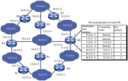
In a complicated Internet as shown in Figure 1-2, the number in each network is the network address, and R stands for a router. The router R8 is directly connected with three networks, so it has three IP addresses and three physical ports, and its routing table is shown in the diagram below:
The H3C S9500 Series Routing Switches (hereinafter referred to as S9500 series) support the configuration of a series of dynamic routing protocols such as RIP, OSPF, IS-IS and BGP, as well as the static routes. In addition, the running switch will automatically obtain some direct routes according to the port state and user configuration.
1.2 Routing Management Policy
For S9500 series, you can configure manually the static route to a specific destination, and configure dynamic routing protocol to interact with other routers on the network. The routing algorithm can also be used to discover routes. For the configured static routes and dynamic routes discovered by the routing protocol, the S9500 series implement unified management. That is, the static routes configured by the user are managed together with the dynamic routes discovered by the routing protocol. The static routes and the routes learned or configured by different routing protocols can also be shared with each other.
1.2.1 Routing Protocols and the Preferences of the Corresponding Routes
Different routing protocols (as well as the static configuration) may generate different routes to the same destination, but not all these routes are optimal. In fact, at a certain moment, only one routing protocol can determine a current route to a specific destination. Thus, each of these routing protocols (including the static configuration) is set with a preference, and when there are multiple routing information sources, the route discovered by the routing protocol with the highest preference will become the current route. Routing protocols and the default preferences (the smaller the value is, the higher the preference is) of the routes learned by them are shown in Table 1-1.
In the table, 0 indicates a direct route. 255 indicates any route from unreliable sources.
Table 1-1 Routing protocols and the default preferences for the routes learned by them
|
Routing protocol or route type |
The preference of the corresponding route |
|
DIRECT |
0 |
|
OSPF |
10 |
|
IS-IS |
15 |
|
STATIC |
60 |
|
RIP |
100 |
|
OSPF ASE |
150 |
|
OSPF NSSA |
150 |
|
IBGP |
256 |
|
EBGP |
256 |
|
UNKNOWN |
255 |
Apart from direct routing, IBGP and EBGP, the preferences of various dynamic routing protocols can be manually configured to meet the user requirements. In addition, the preferences for individual static routes can be different.
1.2.2 Supporting Load Sharing and Route Backup
I. Load sharing
The S9500 series support static equivalent route, permitting to configure multiple routes that reach the same destination and use the same precedence. After you configured static equivalent routes, a packet can reach the same destination through multiple different paths, whose precedence levels are equal. When there is no route that can reach the same destination with a higher precedence, the multiple routes will be adopted. Thus, the router will forward the packets to the destination through these paths according to a certain algorithm so as to implement load sharing.
For the same destination, a specified routing protocol may find multiple different routes with the same precedence and different next hops. If the routing protocol has the highest precedence among all active routing protocols, these multiple routes will be regarded as currently valid routes. Thus, load sharing of IP traffic is ensured in terms of routing protocols.
By far, the S9500 series support eight routes to implement load sharing.
II. Route backup
The S9500 series support route backup. When the main route fails, the system will automatically switch to a backup route to improve the network reliability.
In order to achieve static route backup, the user can configure multiple routes to the same destination according to actual situations. One of the routes has the highest precedence and is called as main route. The other routes have descending precedence levels and are called as backup routes. Normally, the router sends data via main route. When the line fails, the main route will hide itself and the router will choose one from the left routes as a backup route whose precedence is higher than others’ to send data. In this way, the switchover from the main route to the backup route is implemented. When the main route recovers, the router will restore it and re-select route. As the main route has the highest precedence, the router still chooses the main route to send data. This process is the automatic switchover from the backup route to the main route.
1.2.3 Routes Shared Between Routing Protocols
As the algorithms of various routing protocols are different, different protocols may generate different routes, thus bringing about the problem of how to resolve the differences when different routes are generated by different routing protocols. The S9500 series support the import of routes discovered by one routing protocol into another. Each protocol has its own route importing mechanism. For details, refer to the description about importing an external route in the operation manual of the corresponding routing protocol.