- Table of Contents
-
- H3C S9500 Operation Manual-Release1648[v1.24]-03 IP Routing Volume
- 00-1Cover
- 01-IP Routing Protocol Overview
- 02-Static Route Configuration
- 03-RIP Configuration
- 04-OSPF Configuration
- 05-ISIS Configuration
- 06-BGP Configuration
- 07-IP Route Policy Configuration
- 08-Route Capacity Configuration
- 09-Recursive Routing Configuration
- Related Documents
-
| Title | Size | Download |
|---|---|---|
| 05-ISIS Configuration | 163.03 KB |
Table of Contents
1.1.1 Terms of IS-IS Routing Protocol
1.1.2 Two-level Structure of IS-IS Routing Protocol
1.1.3 NSAP Structure of IS-IS Routing Protocol
1.1.4 IS-IS Routing Protocol Packets
1.2.1 Enabling IS-IS and Entering the IS-IS View
1.2.2 Setting Network Entity Title
1.2.3 Enabling IS-IS on the Specified Interface
1.2.4 Setting Priority for DIS Election
1.2.6 Setting Interface Circuit Level
1.2.7 Configuring IS-IS to Redistribute Routes of Other Protocols
1.2.8 Configuring IS-IS Route Filtering
1.2.9 Configuring IS-IS Route Leaking
1.2.10 Setting IS-IS Route Summary
1.2.11 Setting to Generate Default Route
1.2.12 Setting the Preference of IS-IS Protocol
1.2.13 Configuring IS-IS Route Metric Type
1.2.14 Setting IS-IS Link State Routing Cost
1.2.15 Configuring IS-IS Timers
1.2.16 Setting the LSP Refresh Interval
1.2.17 Setting the Age of LSPs
1.2.18 Configuring SPF Parameters
1.2.19 Setting IS-IS Authentication
1.2.20 Setting the Mesh Group of the Interface
1.2.21 Setting Overload Flag Bit
1.2.22 Enabling to Log the Peer Changes
1.2.23 Enabling/Disabling IS-IS Packet Transmission
1.2.25 Resetting All the IS-IS Data Structure
1.2.26 Resetting the Specified IS-IS Peer
1.3 Displaying and Debugging IS-IS
1.4 IS-IS Configuration Example
Chapter 1 IS-IS Configuration
When configuring IS-IS, go to these sections for information you are interested in:
l Displaying and Debugging IS-IS
& Note:
l The term “router” or the router icon in this document refers to a router in a generic sense or an S9500 switch running routing protocols.
l For details about VPN instance, refer to the MPLS VPN Volume.
1.1 Introduction to IS-IS
Intermediate System-to-Intermediate System (IS-IS) intra-domain routing information exchange protocol is designed by the International Organization for Standardization (ISO) for connectionless network protocol (CLNP). This protocol is a dynamic routing protocol. To enable this protocol to support IP routing, IETF expands and modifies IS-IS in RFC1195, applying the protocol to TCP/IP and OSI. The modified IS-IS is called IS-IS or Dual IS-IS.
IS-IS is a link state protocol, which uses the shortest path first (SPF) algorithm. IS-IS and the OSPF protocol are similar in many aspects. As an interior gateway protocol (IGP), IS-IS runs inside an AS.
1.1.1 Terms of IS-IS Routing Protocol
I. Terms of IS-IS routing protocol
l Intermediate System (IS). An IS equals a router of TCP/IP. It is the basic unit in IS-IS protocol used for propagating routing information and generating routes. In the following text, the IS shares the same meaning with the router.
l End System (ES). It equals the host system of TCP/IP. An ES does not process the IS-IS routing protocol, and therefore it can be ignored in the IS-IS protocol.
l Routing Domain (RD). A group of ISs exchange routing information with the same routing protocol in a routing domain.
l Area. Area is the division unit in the routing domain.
l Link State DataBase (LSDB). All the link states in the network form the LSDB. In an IS, at least one LSDB is available. The IS uses the SPF algorithm and the LSDB to generate its own routes.
l Link State Protocol Data Unit (LSPDU). In IS-IS, each IS will generate an LSP which contains all the link state information of the IS. Each IS collects all the LSPs in the local area to generate its own LSDB.
l Network Protocol Data Unit (NPDU). It is the network layer packets of OSI and equals the IP packet of TCP/IP.
l Designated IS (DIS). It is the elected router on the broadcast network.
l Network Service Access Point (NSAP) is the network layer address of OSI. It identifies an abstract network service access point and describes the network address structure for the OSI model.
II. Link types IS-IS routing protocol is applied to
IS-IS routing protocol can run over point-to-point links, such as PPP and HDLC links. IS-IS routing protocol can also run on broadcast links, such as Ethernet and Token Ring links. For a Non-Broadcast Multi-Access (NBMA) network such as ATM, you need to configure sub-interfaces and configure sub-interface type as P2P or broadcast network. IS-IS cannot run over point-to-multipoint links.
1.1.2 Two-level Structure of IS-IS Routing Protocol
I. Two-level structure of IS-IS routing protocol
Two-level structure of IS-IS routing protocol is adopted in a route area to support large-scale networks. A large route area can be divided into one or multiple areas. A Level-1 router manages the intra-area routes. A Level-2 router manages the inter-area routes.
II. Level-1 and Level-2
l Level-1 router
A Level-1 router is responsible for intra-area routes. Level-1 routers and other Level-1 routers or Level-1-2 routers in the same area are neighbors. A Level-1 router maintains a Level-1 LSDB. This LSDB contains intra-area routing information. The packets sent to other areas are forwarded to the closest Level-1-2 router.
l Level-2 router
The Level-2 router is responsible for inter-area route. The Level-2 router and Level-2 routers or Level-1-2 routers in other areas are neighbors. The Level-2 router maintains a Level-2 LSDB. This LSDB contains inter-area routing information. The backbone (which is made up of all Level-2 routers) of a route area is responsible for inter-area communications. The Level-2 routers in the route area must be continuous to ensure the backbone continuity.
l Level-1-2 router
A Level-1-2 router is both a Level-1 router and a Level-2 router. At least one Level-1-2 router in each area connects the area to the backbone network. A Level-1-2 router maintains two LSDBs: the Level-1 LSDB for intra- area route and Level-2 LSDB for inter-area route.
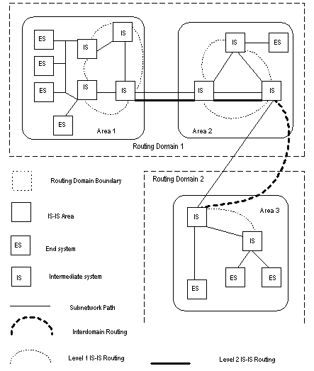
Figure 1-1 illustrates a network running IS-IS routing protocol and composed of Routing Domain 1 and Routing Domain 2. Routing Domain 1 includes two areas, Area 1 and Area 2, and Routing Domain 2 only has Area 3. In Routing Domain 1, the three ISs connected by bold lines compose the area backbone. They are all Level-2 routers. The other 4 ISs not connected by bold line are Level-1-2 routers.
1.1.3 NSAP Structure of IS-IS Routing Protocol
I. Address structure
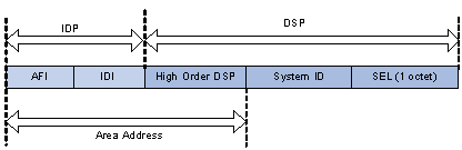
OSI adopts the address structure as shown in Figure 1-2. NSAP includes initial domain part (IDP) and domain specific part (DSP). The IDP is defined by ISO; it consists of authority responsible for assigning the rest of the address and address format. The DSP is allocated by the authority specified in IDP. IDP and DSP are length-variable with a total length of 20 bytes.
l Area Address
IDP includes authority and format identifier (AFI) and initial domain identifier (IDI). AFI defines the format of IDI. DSP has several bytes. The combination of IDP and HO-DSP can identify a route area and an area of the route area, so the combination is called an area address.
In general, you only need to configure an area address for a router. The area addresses of all nodes are the same in an area. To support the seamless combination, segmentation and conversion, the S9500 series support up to three area addresses.
l System ID
System ID uniquely identifies terminal system or router in a route area. You can select length for it. For S9500 series, System ID length is 48 bits (6 bytes). In general, you can obtain System ID according to Router_ID.
If the IP address 168.10.1.1 of the interface LoopBack0 serves as a router_ID for the router, you can use the following method to obtain the System ID:
Turn each part of the IP address 168.10.1.1 into three digits. Add 0 to the front of the part less than three digits.
Divide the expanded address 168.010.001.001 into three parts. Each part contains four digits.
You get the System ID 1680.1000.1001.
You can specify a System ID using different methods. However, you should ensure a System ID can uniquely identify a terminal system or a router.
l SEL
NSAP selector (SEL or N-SEL) functions as the protocol identifier of an IP address. Different transmission protocols correspond to different identifiers. In IS-IS, SELs are 00.
Because the address structure defines clearly an area, a Level-1 router can easily identify the packets not sent to the area where it is located. The Level-1 router forwards the packets to a Level-2 router.
The Level-1 router performs routing within areas by System IDs. If it detects the destination address of a packet does not belong to the area where it is located, it forwards the packet to its closest Level-1-2 router.
The Level-2 router performs intra-area routing according to the area address (IDP + HO-DSP).
II. NET
Network Entity Title (NET) indicates the network layer information, which contains no transfer layer information (SEL=0). You can regard it as a special NSAP.
In general, you can configure a NET for a router. If you will re-divide an area (combine multiple areas or divide an area into multiple areas), you can configure multiple NETs to ensure correct routes in the case of reconfiguration. Because you can configure up to three area addresses, you can only configure up to three NETs.
For example, there is a NET 47.0001.aaaa.bbbb.cccc.00, in which,
Area=47.0001, System ID=aaaa.bbbb.cccc, SEL=00.
For example, there is a NET 01.1111.2222.4444.00, in which,
Area=01, System ID=1111.2222.4444, and SEL=00.
1.1.4 IS-IS Routing Protocol Packets
IS-IS packets are directly encapsulated in the data link frames and mainly fall into three types: Hello, LSP and SNP.
I. Hello packets
Hello packets, also called IIH (IS-to-IS Hello PDUs), can establish and maintain neighbor relationships. A Level-1 router in a broadcast LAN forwards Level-1 LAN IIHs; a Level-2 router in a broadcast LAN forwards Level-2 LAN IIHs; non-broadcast network forwards Point-to-Point IIHs.
II. LSP
Link state packet (LSP) can switch link state information. LSPs fall into two types: Level-1 LSPs and Level-2 LSPs. Level-2 routers transmit Level-2 LSPs; Level-1 routers transmit Level-1 LSPs; Level-1-2 routers transmit both Level-2 LSPs and Level-1 LSPs.
III. SNP
Sequence Number Packet (SNP) can confirm the LSPs last received from neighbors. SNPs function as acknowledge packets, but SNPs function more efficiently. SNP includes complete SNP (CSNP) and partial SNP (PSNP). SNP can be further divided into Level-1 CSNP, Level-2 CSNP, Level-1 PSNP and Level-2 PSNP.
PSNP only lists one or more last received LSP sequence numbers, and confirms multiple LSPs. When detecting asynchronous LSDBs, the system asks neighbors to send new LSPs by PSNPs.
CSNP contains all LSP digest information in an LSDB, synchronizing LSDBs for neighbor routers. On a broadcast network, a DIS sends CSNPs periodically (the default sending period is 10 seconds). Over a point-to-point link, a DIS sends CSNPs only when the neighbors are established for the first time.
1.2 Configuring IS-IS
Among the following configurations, the configuration of enabling IS-IS is required, while other configurations are optional.
IS-IS configuration includes:
1) IS-IS basic configuration
l Enabling IS-IS and Entering the IS-IS View
l Setting Network Entity Title
l Enabling IS-IS on the Specified Interface
l Setting Priority for DIS Election
l Setting Interface Circuit Level
2) Configuration related to IS-IS route
l Configuring IS-IS to Redistribute Routes of Other Protocols
l Configuring IS-IS Route Filtering
l Configuring IS-IS Route Leaking
l Setting to Generate Default Route
3) IS-IS-related configurations
l Setting the Preference of IS-IS Protocol
l Configuring IS-IS Route Metric Type
l Setting IS-IS Link State Routing Cost
l Setting the LSP Refresh Interval
4) Configuration related to IS-IS networking
l Setting IS-IS Authentication
l Setting the Mesh Group of the Interface
l Enabling to Log the Peer Changes
l Enabling/Disabling IS-IS Packet Transmission
5) Some operation commands
l Resetting All the IS-IS Data Structure
l Resetting the Specified IS-IS Peer
1.2.1 Enabling IS-IS and Entering the IS-IS View
After creating an IS-IS routing process, you should also activate this routing process on an interface that may correlate with another router. After that, the IS-IS protocol can be started and run.
Perform the following configuration in system view to enable IS-IS and enter IS-IS view
|
To do... |
Use the command... |
|
Enable IS-IS and enter IS-IS view |
isis [ tag ] |
The tag argument identifies the IS-IS process. In the present version, only one IS-IS process is allowed.
By default, the IS-IS routing process is disabled.
1.2.2 Setting Network Entity Title
Network Entity Title (NET) defines the current IS-IS area address and the system ID of the router.
Perform the following configurations in IS-IS view to set/delete a NET:
|
To do... |
Use the command... |
|
Set a NET |
network-entity network-entity-title |
|
Delete a NET |
undo network-entity network-entity-title |
The format of the network-entity-title argument is X…X.XXXXXXXXXXXX.XX, where “X…X” is the area address, the twelve Xs in the middle are the System ID of the router. The last XX should be 00.
1.2.3 Enabling IS-IS on the Specified Interface
After enabling IS-IS, you need to specify on which interfaces IS-IS will be run.
Perform the following configuration in interface view to enable/disable IS-IS on the specified interface:
|
To do... |
Use the command... |
|
Enable IS-IS on the specified Interface |
isis enable [ tag ] |
|
Cancel this designation |
undo isis enable [ tag ] |
1.2.4 Setting Priority for DIS Election
In the broadcast network, IS-IS needs to elect a DIS from all the routers.
When you need to select a DIS from the IS-IS neighbors on the broadcast network, you should select level-1 DIS and level-2 DIS respectively. The higher the priority is, the more possible it is selected. If there are two or more routers with the highest priority in the broadcast network, the one with the greatest MAC address will be selected. If all the adjacent routers' priorities are 0, the one with the greatest MAC address will be selected.
The DISs of Level-1 and Level-2 are elected separately. You can set different priorities for DIS election at different levels.
Perform the following configuration in interface view to set/restore priority for DIS election:
|
To do... |
Use the command... |
|
Set the priorities for DIS election on the interface |
isis dis-priority value [ level-1 | level-2 ] |
|
Restore the default priorities for DIS election on the interface |
undo isis dis-priority [ level-1 | level-2 ] |
By default, the interface priority is 64. If the level-1 or level-2 is not specified, it defaults to setting the priority of both Level-1 and Level-2.
1.2.5 Setting Router Type
Based upon the position of the router, the levels can be divided into Level-1 (intra-domain router), Level-2 (inter-domain router) and Level-1-2 (that is, intra-domain router as well as inter-domain router).
Perform the following configuration in IS-IS view to set/restore the router type:
|
To do... |
Use the command... |
|
Set the router type |
is-level { level-1 | level-1-2 | level-2 } |
|
Restore the default router type |
undo is-level |
By default, the router type is level-1-2.
1.2.6 Setting Interface Circuit Level
Perform the following configuration in interface view to set/restore the interface circuit level:
|
To do... |
Use the command... |
|
Set the interface circuit level |
isis circuit-level [ level-1 | level-1-2 | level-2 ] |
|
Restore the default interface circuit level |
undo isis circuit-level |
& Note:
The modification to the interface circuit level is meaningful only when the router to which the interface belongs is of Level-1-2 type. Otherwise, the type of the router determines the level of adjacency relation.
You can set the circuit level to limit what adjacency can be established for the interface. For example, Level-1 interface can only have Level-1 adjacency. Level-2 interface can only have Level-2 adjacency. For the Level-1-2 router, you can configure some interfaces to Level-2 to prevent transmitting Level-1 Hello packets to Level-2 backbone so as to save the bandwidth. However, Level-1 and Level-2 use the same kind of Hello packet over the p2p link, and therefore such setting is unnecessary in this case.
By default, the circuit-level on the interface is level-1-2.
1.2.7 Configuring IS-IS to Redistribute Routes of Other Protocols
For IS-IS, the routes discovered by other routing protocols are processed as the routes outside the routing domain. When redistributing the routes of other protocols, you can specify the default cost for them.
When IS-IS redistributes routes, you can also specify to redistribute the routes to Level-1, Level-2 or Level-1-2.
Perform the following configuration in IS-IS view to enable/disable redistributing routes of other protocols:
|
To do... |
Use the command... |
|
Redistribute routes of other protocols |
import-route protocol [ cost value | type { external | internal } | [ level-1 | level-1-2 | level-2 ] | route-policy route-policy-name ]* |
|
Disable redistributing routes from other protocols |
undo import-route protocol [ cost value | type { external | internal } | [ level-1 | level-1-2 | level-2 ] | route-policy route-policy-name ]* |
If the level is not specified in the command for redistributing the route, it defaults to redistributing the routes into level-2.
protocol specifies the routing protocol sources that can be redistributed, which can be direct, static, rip, bgp, ospf, OSPF-ASE, OSPF-NSSA, and NAT.
By default, IS-IS does not redistribute routing information from any other protocols. When routes are redistributed from BGP, the allow-ibgp keyword can be specified to redistribute IBGP routes.
For more about redistributing routing information, refer to IP Route Policy Configuration.
1.2.8 Configuring IS-IS Route Filtering
IS-IS can filter the received and advertised routes according to the access control list (ACL) specified by acl-number.
Perform the following configuration in IS-IS view.
I. Configuring to filter the routes received by IS-IS
Follow these steps to enable/disable filtering received routes
|
To do... |
Use the command... |
|
Configure to filter the received routes |
filter-policy acl-number import |
|
Cancel filtering the received routes |
undo filter-policy acl-number import |
II. Configuring to filter the advertised routes
Follow these steps to enable/disable filtering advertised routes
|
To do... |
Use the command... |
|
Configure to filter the routes advertised by IS-IS |
filter-policy acl-number export [ routing-protocol ] |
|
Configure not to filter the routes advertised by IS-IS |
undo filter-policy acl-number export [routing-protocol ] |
By default, IS-IS does not filter the route advertised by other routing protocols.
protocol specifies the routing protocol sources for advertising routes, which can be direct, static, rip, bgp, ospf, ospf-ase, and ospf-nssa.
& Note:
l The filter-policy import command only filters the IS-IS routes received from the neighbors, and routes that cannot pass the filter will not be added to the routing table.
l The filter-policy export command only takes effect on the routes redistributed by the import-route command. If you configure the switch with only the filter-policy export command, but without configuring the import-route command to redistribute other external routes, then the filter-policy export command does not take effect.
l If the filter-policy export command does not specify which route to be filtered, then the all the routes redistributed by the import-route command will be filtered.
l If no rule is specified in the filter-policy command, all routes are denied by default.
1.2.9 Configuring IS-IS Route Leaking
With the IS-IS route leaking function, a Level-1-2 router can advertise the routing information of a Level-2 area it knows to a Level-1 router.
Perform the following configuration in IS-IS view.
Follow these steps to enable/disable IS-IS route leaking:
|
To do... |
Use the command... |
|
Enable IS-IS route leaking |
import-route isis level-2 into level-1 [ acl acl-number ] |
|
Disable IS-IS route leaking |
undo import-route isis level-2 into level-1 [ acl acl-number ] |
By default, a Level-2 router does not advertise its routing information to a Level-1 area.
1.2.10 Setting IS-IS Route Summary
Users can set the routes with the same next hops as one route in the routing table. Perform the following configurations in IS-IS view to set/delete a summary route:
|
To do… |
Use the command... |
|
Set a summary route |
summary ip-address ip-mask [ level-1 | level-1-2 | level-2 ] |
|
Delete the summary route |
undo summary ip-address ip-mask [ level-1 | level-1-2 | level-2 ] |
By default, the system disables route summary.
1.2.11 Setting to Generate Default Route
In the IS-IS route domain, the Level-1 router only has the LSDB of the local area, so it can only generate the routes in the local areas. But the Level-2 router has the backbone LSDB in the IS-IS route domains and generates the backbone network routes only. If a Level-1 router in one area wants to forward the packets to other areas, it needs to first forward the packets to the closest Level-1-2 router in the local area along its default route. You do not need to configure the default Level-1 route, but need to manually configure the default Level-2 route.
Perform the following configurations in IS-IS view to enable/disable generating the default route:
|
To do... |
Use the command... |
|
Enable generating the default route |
default-route-advertise [ route-policy route-policy-name ] |
|
Disable generating default route |
undo default-route-advertise [ route-policy route-policy-name ] |
The default route generated by this command will only be redistributed to the router at the same level.
1.2.12 Setting the Preference of IS-IS Protocol
For a router running several routing protocols, there is an issue of sharing and selecting the routing information among all the routing protocols. The system sets a preference for each routing protocol. When various routing protocols find the route to the same destination, the protocol with the higher preference will take effect.
Perform the following configuration in IS-IS view to configure/restore the preference of IS-IS protocol:
|
To do… |
Use the command... |
|
Configure the preference of IS-IS protocol |
preference value |
|
Restore the default preference of IS-IS protocol |
undo preference |
By default, the preference of IS-IS route is 15.
1.2.13 Configuring IS-IS Route Metric Type
IS-IS routing protocol has two styles of route metric:
l Narrow: The value of route metric ranges from 1 to 63.
l Wide: The value of route metric ranges from 1 to 16,777,215.
A router can choose either or both of the styles.
Perform the following configuration in IS-IS view to configure/restore the style for route metric values of IS-IS packets:
|
To do... |
Use the command... |
|
Configure the style for route metric values of IS-IS packets |
cost-style { narrow | wide | wide-compatible | { compatible | narrow-compatible } [ relax-spf-limit ] } |
|
Restore the default settings |
undo cost-style |
By default, IS-IS only receives and sends the packets whose route metric is in narrow style.
1.2.14 Setting IS-IS Link State Routing Cost
Users can configure the interface cost, namely, the default routing cost.
Perform the following configuration in interface view to set/restore IS-IS link state routing cost:
|
To do... |
Use the command... |
|
Set the routing cost of the interface |
isis cost value [ level-1 | level-2 ] |
|
Restore the default routing cost of the interface |
undo isis cost [ level-1 | level-2 ] |
If the level is not specified, the default setting is Level-1 routing cost.
The value argument is configured according to the link state of the interface.
By default, the routing cost of IS-IS on an interface is 10.
1.2.15 Configuring IS-IS Timers
I. Setting the Hello packet broadcast interval
IS-IS periodically sends the Hello packets from the interface and the routers maintain the adjacency through the transmitting/receiving of the Hello packets. The Hello packet interval can be modified.
Perform the following configuration in interface view to set/restore the Hello packet broadcast interval:
|
To do... |
Use the command... |
|
Set Hello packet interval, measured in seconds |
isis timer hello seconds [ level-1 | level-2 ] |
|
Restore the default Hello packet interval on the interface |
undo isis timer hello [ level-1 | level-2 ] |
Usually, two types of Hello packets are sent over a broadcast link: Level-1 and Level-2 Hello packets. For different packets, different broadcast intervals should be set. However, there are two exceptions. One is when there is no level separation in the link, parameters of Level-1 and Level-2 need not be specified in the command (adopt the default values). Therefore, the system will set the broadcast intervals of all packets as that of the level-1 Hello packet. The other is if Hello packets are not separated according to level-1 and level-2 on the p2p links, the attribute of the packets need not be set either.
By default, Hello packets are transmitted on an interface every 10 seconds.
This command specifies to send Hello packets of the corresponding levels in the Fast Hello mode (by setting the minimum value of Hello interval to 1 second). If the number of packets is not specified in the related command, three Hello packets will be sent per second.
Perform the following configuration in interface view to configure/restore sending Hello packets of a level in the Fast Hello mode:
|
To do... |
Use the command... |
|
Configure to send Hello packets of the corresponding levels in the Fast Hello mode |
isis timer hello minimal [ level-1 | level-2 ] |
|
Restore the default value of Hello interval in the Fast Hello mode. |
undo isis timer hello minimal [ level-1 | level-2 ] |
If neither level-1 nor level-2 is specified, the default setting is Level-1 and Level-2 Hello interval. Namely, the command works on both Level-1 and Level-2.
II. Setting the CSNP packet broadcast interval
The CSNP packet is transmitted by the DIS over the broadcast network to synchronize the link state database (LSDB). The CSNP packet is regularly broadcast over the broadcast network at an interval, which can be set by users.
Perform the following configuration in interface view to set/restore the CSNP packet broadcast interval:
|
To do... |
Use the command... |
|
Set the CSNP packet broadcast interval |
isis timer csnp seconds [ level-1 | level-2 ] |
|
Restore the default CSNP packet broadcast interval on the interface |
undo isis timer csnp [ level-1 | level-2 ] |
If the level is not specified, it defaults to setting CSNP packet broadcast interval for Level-1.
By default, the CSNP packet is transmitted via interface every 10 seconds.
III. Setting LSP packet generation interval
As specified in the IS-IS protocol, when an event takes place, the related LSP packet should be generated again. If LSP packets are generated frequently, a large amount of resources will be occupied and the route’s efficiency will be affected. The exponent digression method can improve the efficiency to a certain degree. The LSP packet generation interval can you be configured as per the actual requirement.
Perform the following configuration in IS-IS view to set/restore the LSP packet generation interval:
|
To do... |
Use the command... |
|
Set the LSP packet generation interval |
timer lsp-generation x y z [ level-1 | level-2 ] |
|
Restore the default value of LSP packet generation interval |
undo timer lsp-generation x y z [ level-1 | level-2 ] |
IV. Setting the LSP packet transmission interval
LSP carries the link state records for propagation throughout the area.
Perform the following configuration in interface view to set/restore the LSP packet transmission interval:
|
To do... |
Use the command... |
|
Set LSP packet interval on the interface. |
isis timer lsp time |
|
Restore the default LSP packet interval on the interface |
undo isis timer lsp |
By default, the LSP packet is transmitted via the interface every 33 milliseconds.
V. Setting LSP packet retransmission interval
Over a p2p link, if the local end does not receive the response within a period of time after it sends an LSP packet, it considers that the originally transmitted LSP packet has been lost or dropped. In order to guarantee the transmission reliability, the local router will retransmit the original LSP packet.
Perform the following configuration in interface view to set/restore LSP packet retransmission interval:
|
To do... |
Use the command... |
|
Set the retransmission interval of the LSP packet over P2P links |
isis timer retransmit seconds |
|
Restore the default retransmission interval of the LSP packet over P2P links |
undo isis timer retransmit |
By default, the LSP packet is transmitted every five seconds over the p2p link.
VI. Configuring the number of invalid Hello packets for the interface
The router maintains the adjacency by sending/receiving Hello packets. When receiving no Hello packets from the peer within a time interval, the local router considers the neighbors invalid. The time interval is called Holddown time for IS-IS.
Setting the number of invalid Hello packets can adjust the Holddown time in IS-IS. That is to say, after continuously receiving no specified number of Hello packets, the router considers the neighbors invalid.
Follow these steps to set/restore the number of invalid Hello packets for the interface:
|
To do... |
Use the command... |
|
Set the number of invalid Hello packets |
isis timer holding-multiplier value [ level-1 | level-2 ] |
|
Restore the default setting |
undo isis timer holding-multiplier [ level-1 | level-2 ] |
By default, the number of the invalid Hello packets is set to 3.
If this command does not specify level-1 or level-2, the system considers the invalid Hello packets to be set for both Level-1 and Level-2 routers.
1.2.16 Setting the LSP Refresh Interval
IS-IS periodically advertises all the local LSPs for LSDB synchronization in the entire area.
Perform the following configuration in IS-IS view to set/restore the LSP refresh interval:
|
To do… |
Use the command… |
|
Set LSP refreshment interval |
timer lsp-refresh seconds |
|
Restore the default LSP refresh interval |
undo timer lsp-refresh |
The default LSP refresh interval is 900 seconds (15 minutes).
1.2.17 Setting the Age of LSPs
When a router generates an LSP, it fills the maximum age into the LSP. When other routers receive this LSP, its age begins to decrease. If no updated LSP is received with the age time, this LSP will be deleted from the LSDB.
Perform the following configuration in IS-IS view to set/restore the age of LSPs
|
To do… |
Use the command… |
|
Set the age of LSPs |
timer lsp-max-age seconds |
|
Restore the default LSP age |
undo timer lsp-max-age |
The default LSP age is 1200 seconds (20 minutes).
1.2.18 Configuring SPF Parameters
I. Setting the SPF calculation interval
When the IS-IS LSDB changes, the router will compute the shortest path tree again. However, the immediate calculation upon every change will occupy too many resources and affect the efficiency of the router. With the SPF calculation interval set, when the LSDB changes, the SPF algorithm will be run after the interval.
Perform the following configuration in IS-IS view to configure/restore the SPF calculation interval
|
To do… |
Use the command… |
|
Set the SPF calculation interval |
timer spf second [ level-1 | level-2 ] |
|
Restore the default |
undo timer spf [ level-1 | level-2 ] |
If no level is specified, the SPF calculation interval applies to Level-1.
The default SPF calculation interval is 10 seconds.
II. Setting the SPF calculation duration for each slice
When there is a large number of routes in the routing table (over 150,000), an SPF calculation may occupy the system resources for a long time. To solve this problem, an SPF calculation can be split into slices.
Perform the following configuration in IS-IS view to set/restore the SPF calculation duration for each slice:
|
To do… |
Use the command… |
|
Set the SPF calculation duration for each slice |
spf-slice-size seconds |
|
Restore the default |
undo spf-slice-size |
By default, an SPF calculation is not divided into slices but runs until it ends, which can also be implemented by setting the seconds argument to 0.
After the calculation duration for each slice is set, the interval between slices is one second.
Normally, you are not recommended to modify the default configuration. When the number of routes is between 150000 and 200000, it is recommended to set the seconds argument to 1, that is, the duration time for each SPF calculation slice is 1 second.
III. Configuring SPF to release CPU actively
To prevent an SPF calculation from occupying the system resources for a long time, which affects the response speed of the console, SPF can be set to automatically release the system CPU resources after processing a certain number of routes and the unprocessed routes will be calculated after one second.
Perform the following configuration in IS-IS view to configure SPF to release CPU actively:
|
To do… |
Use the command… |
|
Specify the number of routes to process before releasing CPU |
spf-delay-interval number |
|
Restore the default |
undo spf-delay-interval |
The default number is 2500.
1.2.19 Setting IS-IS Authentication
I. Setting interface authentication
The authentication password set on the interface is mainly used in the Hello packet so as to confirm the validity and correctness of its peers. The authentication passwords at the same level of all the interfaces of a network should be identical.
Perform the following configuration in interface view to set/delete interface authentication password:
|
To do... |
Use the command... |
|
Set authentication password |
isis authentication-mode { simple | md5 } password [ { level-1 | level-2 } [ ip | osi ] ] |
|
Delete authentication-mode password |
undo isis authentication-mode { simple | md5 } |
By default, the interface is not configured with any authentication password nor performs authentication. If the level is not specified, it defaults to setting the authentication password of both Level-1 and Level-2.
II. Setting IS-IS area or IS-IS routing domain authentication password
You can configure the IS-IS area or the IS-IS routing domain with authentication password.
If area authentication is needed, the area authentication password will be encapsulated into the level-1 LSP, CSNP and PSNP packets, in the specified mode. If other routers in the same area also have started the area authentication, their authentication modes and passwords must be identical to those of their neighbors, so that they can work normally. Similarly, for domain authentication, the password will also be encapsulated into the level-2 LSP, CSNP and PSNP packets in the specified mode. If the routers in the backbone layer (level-2) also need domain authentication, their authentication mode and password must be identical to those of their neighbors.
Note that the passwords for authentication of the routers on the same network segment must be identical.
Perform the following configurations in IS-IS view to set/delete IS-IS authentication password:
|
To do... |
Use the command... |
|
Set authentication-mode password |
area-authentication-mode { simple | md5 } password [ ip | osi ] |
|
Delete authentication-mode password |
|
|
Set routing domain authentication password |
domain-authentication-mode { simple | md5 } password [ ip | osi ] |
|
Delete routing domain authentication password |
undo domain-authentication-mode { simple | md5 } [ ip | osi ] |
By default, the system does not require password or perform authentication.
III. Setting IS-IS to use the MD5 algorithm compatible with that of other vendors
You must configure this command when the switch needs to authenticate the devices of other vendors using MD5 algorithm in IS-IS.
Perform the following configuration in IS-IS view to configure IS-IS to use the MD5 algorithm compatible with that of the other vendors:
|
To do... |
Use the command... |
|
Set IS-IS to use the MD5 algorithm compatible with that of the other vendors |
md5-compatible |
|
Set IS-IS to use the default MD5 algorithm |
undo md5-compatible |
By default, the system uses the MD5 algorithm in IS-IS which is compatible with that of H3C.
& Note:
You can use this command if the switch cannot interoperate with the peer switch or router through MD5 authentication. You have to execute the reset isis command after enabling or disabling this command.
1.2.20 Setting the Mesh Group of the Interface
On an NBMA network, the interface of a router will flood a received LSP to other interfaces. However, this processing method applied to a network with high connectivity and multiple point-to-point links will cause repeated LSP flooding and waste bandwidth.
To avoid such a problem, you can configure several interfaces into a mesh group. The interface will flood it outside the group only.
Perform the following configuration in interface view to set/remove the mesh group of the interface:
|
To do... |
Use the command... |
|
Add an interface to a mesh group |
isis mesh-group { mesh-group-number | mesh-blocked } |
|
Remove the interface from a mesh group |
undo isis mesh-group |
By default, the LSP is flooded normally from the interface. When configured with the mesh-blocked keyword, it will not flood the LSP to other interfaces.
Thus the IS-IS configuration tasks on the interface are finished. The following sections discuss how to configure other parameters of IS-IS.
1.2.21 Setting Overload Flag Bit
Sometimes, the router in the IS-IS domain may encounter some problems in operation thus errors may occur in the whole routing area. In order to avoid this problem, you can set the overload flag bit for this router.
With the overload flag bit set, the router cannot become the transit node in the network; that is, the router stops forwarding any packets.
Perform the following configurations in IS-IS view to set/remove overload flag bit:
|
To do... |
Use the command... |
|
Set overload flag bit |
set-overload |
|
Remove the overload flag bit |
undo set-overload |
By default, no over load bit is set.
1.2.22 Enabling to Log the Peer Changes
After peer changes log is enabled, the IS-IS peer changes will be output on the configuration terminal until the log is disabled.
Perform the following configuration in IS-IS view to enable/disable logging the peer changes:
|
To do... |
Use the command... |
|
Enable peer changes log |
log-peer-change |
|
Disable peer changes log |
undo log-peer-change |
By default, the peer changes log is disabled..
1.2.23 Enabling/Disabling IS-IS Packet Transmission
To prevent the IS-IS routing information from being obtained by some router in a certain network, the silent-interface command can be used to allow receiving, but not sending, IS-IS packets through the interface connecting with the router.
Perform the following configuration in IS-IS view to enable/disable IS-IS packet transmission:
|
To do... |
Use the command... |
|
Disable the interface from sending IS-IS packets |
silent-interface interface-type interface-number |
|
Enable the interface to send IS-IS packets |
undo silent-interface interface-type interface-number |
By default, the interface is allowed to receive and send IS-IS packets.
The silent-interface command is only used to restrain the IS-IS packets not to be sent on the interface, but the interface routes can still be sent from other interfaces. On a switch, this command can disable/enable the specified VLAN interface to send IS-IS packets.
1.2.24 Configuring IS-IS GR
The network is interrupted temporarily when an IS-IS router is restarted because the neighbor relationship of this router with other neighbors is removed and LSP packets are flooded. The GR feature of IS-IS can solve this problem. This feature enables the restarted router to notify its neighbors of its restart state and permits the neighbors to establish new adjacency relation without disconnection. The GR feature of IS-IS has the following benefits:
l This GR feature is applied on the restarted routers and firstly started routers and enables the restarted routers to send connection requests to neighbors again instead of ending the adjacency relation.
l This GR feature reduces the influence on the network caused by waiting for database synchronization before generating LSP packets to the utmost extent.
l This feature sets overload flag bits in LSP packets until database synchronization for the firstly started routers, so that route loops will not occur in the network.
Follow these steps to configure IS-IS GR:
|
To do... |
Use the command... |
Description |
|
Enter system view |
system-view |
— |
|
Enable the IS-IS routing process and enter IS-IS view |
isis [ process id ] |
Required The IS-IS routing process can not be enabled by default |
|
Enable IS-IS GR capability |
graceful-restart |
Required IS-IS GR capability is disabled by default |
|
Configure the restart interval |
graceful-restart interval timer |
Optional The restart interval is 300 seconds by default |
|
Configure SA suppression when a router is restarted |
graceful-restart suppress-sa |
Required By default, the SA bit is not suppressed |
|
Display the IS-IS graceful restart status |
display isis graceful-restart status [ l1 | l2 | level-1 | level-2 ] |
You can execute the display command in any view. |
& Note:
l The restart interval specifies the interval of restarting routers. The restart interval is set as holdtime in Hello PDU of IS-IS. In this way, the neighbors of a router will not break adjacency relations with it when it is restarted.
l The restarted router suppresses SA bits in Hello PDU to request its neighbors to suppress advertising the adjacency relation in the set time range. SA bits are deleted when the database of this router is synchronized. You can use the graceful-restart suppress-sa command to disable this function if you do not want to enable this router to set SA bits in Hello PDU. With the help of this feature, the black hole effect caused by sending/receiving LSP packets can be avoided during the GR process.
1.2.25 Resetting All the IS-IS Data Structure
When it is necessary to refresh some LSPs immediately, perform the following configuration in user view.
Follow these steps to reset all the IS-IS data structures:
|
To do... |
Use the command... |
|
Reset the IS-IS data structure |
reset isis all |
By default, the IS-IS data structure is not cleared.
1.2.26 Resetting the Specified IS-IS Peer
When it is necessary to connect a specified peer again, perform the following configuration in user view.
Follow these steps to reset the specified IS-IS peer:
|
To do... |
Use the command... |
|
Reset the specified IS-IS peer |
reset isis peer system-id |
By default, the IS-IS peer is not cleared.
1.3 Displaying and Debugging IS-IS
|
To do... |
Use the command... |
Remarks |
|
Display the IS-IS graceful restart status |
display isis graceful-restart status [ l1 | l2 | level-1 | level-2 ] |
Available in any view |
|
Display the IS-IS-enabled interfaces |
display isis interface [ interface-type interface-number ] [ verbose ] |
Available in any view |
|
Display IS-IS LSDB |
display isis lsdb [ [ l1 | l2 | level-1 | level-2 ] | [ [ LSPID | local ] | verbose ]* ]* |
Available in any view |
|
Display IS-IS SPF calculation log |
display isis spf-log |
Available in any view |
|
Display IS-IS routing information |
display isis route |
Available in any view |
|
Display IS-IS neighbor information |
display isis peer [ verbose ] |
Available in any view |
|
Display mesh group information |
display isis mesh-group |
Available in any view |
|
Enable IS-IS debugging |
debugging isis { adjacency | all | authentication-error | checksum-error | circuit-information | configuration-error | datalink-receiving-packet | datalink-sending-packet | general-error | interface-information | memory-allocating | receiving-packet-content | restart-events | self-originate-update | sending-packet-content | snp-packet | spf-event | spf-summary | spf-timer | task-error | timer | update-packet } |
Available in user view |
|
Disable IS-IS debugging |
undo debugging isis { adjacency | all | authentication-error | checksum-error | circuit-information | configuration-error | datalink-receiving-packet | datalink-sending-packet | general-error | interface-information | memory-allocating | receiving-packet-content | restart-events | self-originate-update | sending-packet-content | snp-packet | spf-event | spf-summary | spf-timer | task-error | timer | update-packet } |
Available in user view |
1.4 IS-IS Configuration Example
I. Network requirements
As shown in Figure 1-3, Switch A, Switch B, Switch C and Switch D belong to the same autonomous system. The IS-IS routing protocol is running in these four switches so as to implement route interconnection. In the network design, Switch A, Switch B, Switch C, and Switch D belong to the same area.
II. Network diagram
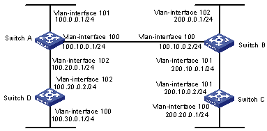
Figure 1-3 IS-IS configuration example
III. Configuration procedure
# Configure Switch A.
[Switch A] isis
[Switch A-isis] network-entity 86.0001.0000.0000.0005.00
[Switch A] interface vlan-interface 100
[Switch A-Vlan-interface100] ip address 100.10.0.1 255.255.255.0
[Switch A-Vlan-interface100] isis enable
[Switch A] interface vlan-interface 101
[Switch A-Vlan-interface101] ip address 100.0.0.1 255.255.255.0
[Switch A-Vlan-interface101] isis enable
[Switch A] interface vlan-interface 102
[Switch A-Vlan-interface102] ip address 100.20.0.1 255.255.255.0
[Switch A-Vlan-interface102] isis enable
# Configure Switch B.
[Switch B] isis
[Switch B-isis] network-entity 86.0001.0000.0000.0006.00
[Switch B] interface vlan-interface 101
[Switch B-Vlan-interface101] ip address 200.10.0.1 255.255.255.0
[Switch B-Vlan-interface101] isis enable
[Switch B] interface vlan-interface 102
[Switch B-Vlan-interface102] ip address 200.0.0.1 255.255.255.0
[Switch B-Vlan-interface102] isis enable
[Switch B] interface vlan-interface 100
[Switch B-Vlan-interface100] ip address 100.10.0.2 255.255.255.0
[Switch B-Vlan-interface100] isis enable
# Configure Switch C.
[Switch C] isis
[Switch C-isis] network-entity 86.0001.0000.0000.0007.00
[Switch C] interface vlan-interface 101
[Switch C-Vlan-interface101] ip address 200.10.0.2 255.255.255.0
[Switch C-Vlan-interface101] isis enable
[Switch C] interface vlan-interface 100
[Switch C-Vlan-interface100] ip address 200.20.0.1 255.255.255.0
[Switch C-Vlan-interface100] isis enable
# Configure Switch D.
[Switch D] isis
[Switch D-isis] network-entity 86.0001.0000.0000.0008.00
[Switch D] interface vlan-interface 102
[Switch D-Vlan-interface102] ip address 100.20.0.2 255.255.255.0
[Switch D-Vlan-interface102] isis enable
[Switch D] interface vlan-interface 100
[Switch D-Vlan-interface100] ip address 100.30.0.1 255.255.255.0
[Switch D-Vlan-interface100] isis enable