- Table of Contents
-
- H3C S9500 Operation Manual-Release1648[v1.24]-03 IP Routing Volume
- 00-1Cover
- 01-IP Routing Protocol Overview
- 02-Static Route Configuration
- 03-RIP Configuration
- 04-OSPF Configuration
- 05-ISIS Configuration
- 06-BGP Configuration
- 07-IP Route Policy Configuration
- 08-Route Capacity Configuration
- 09-Recursive Routing Configuration
- Related Documents
-
| Title | Size | Download |
|---|---|---|
| 04-OSPF Configuration | 300.9 KB |
Table of Contents
1.1.2 Process of OSPF Route Calculation
1.1.5 Basic Concepts Related to OSPF
1.1.6 OSPF Features Supported by the S9500 Series
1.2.1 Working Mechanism of OSPF GR
1.2.2 Packet Format of OSPF GR
1.2.3 OSPF GR Features Supported by CMW
1.3.4 Specifying an Interface to Run OSPF
1.3.5 Configuring OSPF to Import Routes of Other Protocols
1.3.6 Configuring OSPF to Advertise Default Routes
1.3.7 Configuring OSPF Route Filtering
1.3.8 Configuring the Route Summary of OSPF
1.3.9 Setting OSPF Route Preference
1.3.10 Configuring OSPF Timers
1.3.11 Configuring the Network Type of the OSPF Interface
1.3.12 Configuring NBMA Neighbors for OSPF
1.3.13 Setting the Interface Priority for DR Election
1.3.14 Configuring an Interval Required for Sending LSU Packets
1.3.15 Configuring the Cost for Sending Packets on an Interface
1.3.16 Configuring to Fill the MTU Field When an Interface Transmits DD Packets
1.3.17 Setting a Shortest Path First (SPF) Calculation Interval for OSPF
1.3.18 Disabling the Interface to Send OSPF Packets
1.3.19 Configuring OSPF Authentication
1.3.20 Configuring OSPF Virtual Link
1.3.21 Configuring Stub Area of OSPF
1.3.22 Configuring NSSA Area of OSPF
1.3.23 Setting the Switch for Adjacency State Output
1.3.24 Configuring OSPF and Network Management System
1.3.26 Resetting the OSPF Process
1.4 Displaying and Debugging OSPF
1.5 OSPF Configuration Example
1.5.1 Configuring DR Election Based on OSPF Priority
1.5.2 Configuring OSPF Virtual Link
1.5.3 OSPF GR Configuration Example
1.6 Troubleshooting OSPF Configuration
Chapter 1 OSPF Configuration
When configuring OSPF, go to these sections for information you are interested in:
l Displaying and Debugging OSPF
l Troubleshooting OSPF Configuration
& Note:
l The term “router” or the router icon in this document refers to a router in a generic sense or an S9500 switch running routing protocols.
l For details about VPN instance, refer to the MPLS VPN Volume.
1.1 OSPF Overview
1.1.1 Introduction to OSPF
Open Shortest Path First (OSPF) is an Interior Gateway Protocol based on the link state developed by IETF. At present, OSPF version 2 (RFC2328) is used, which is available with the following features:
l Applicable scope: It can support networks in various sizes and can support several hundreds of routers at maximum.
l Fast convergence: It can transmit the update packets instantly after the network topology changes so that the change is synchronized in the AS.
l Loop-free: Since the OSPF calculates routes with the shortest path tree algorithm according to the collected link states, it is guaranteed that no loop routes will be generated from the algorithm itself.
l Area partition: It allows the network of AS to be divided into different areas for the convenience of management so that the routing information transmitted between the areas is abstracted further, hence to reduce the network bandwidth consumption.
l Equal-cost multi-route: Support multiple equal-cost routes to a destination.
l Routing hierarchy: OSPF has a four-level routing hierarchy. It prioritizes the routes to be intra-area, inter-area, external type-1, and external type-2 routes.
l Authentication: It supports the interface-based packet authentication so as to guarantee the security of the route calculation.
l Multicast transmission: Support multicast address to receive and send packets.
1.1.2 Process of OSPF Route Calculation
The routing calculation process of the OSPF protocol is as follows:
l Each OSPF-capable router maintains a Link State Database (LSDB), which describes the topology of the whole AS. According to the network topology around itself, each router generates a Link State Advertisement (LSA). The routers on the network transmit the LSAs among them by transmitting the protocol packets to each others. Thus, each router receives the LSAs of other routers and all these LSAs compose its LSDB.
l LSA describes the network topology around a router, so the LSDB describes the network topology of the whole network. Routers can easily transform the LSDB to a weighted directed graph, which actually reflects the topology architecture of the whole network. Obviously, all the routers get a graph exactly the same.
l A router uses the SPF algorithm to calculate the shortest path tree with itself as the root, which shows the routes to the nodes in the autonomous system. The external routing information is the leave node. A router, which advertises the routes, also tags them and records the additional information of the autonomous system. Obviously, the routing tables obtained by different routers are different.
Furthermore, to enable individual routers to broadcast their local state information to the entire AS, any two routers in the environment should establish adjacency between them. In this case, however, the changes that any router takes will result in multiple transmissions, which are not only unnecessary but also waste the precious bandwidth resources. To solve this problem, “Designated Router” (DR) is defined in the OSPF. Thus, all the routers only send information to the DR for broadcasting the network link states in the network. Thereby, the number of router adjacent relations on the multi-access network is reduced.
OSPF supports interface-based packet authentication to guarantee the security of route calculation. Also, it transmits and receives packets by IP multicast (224.0.0.5 and 224.0.0.6).
1.1.3 OSPF Packets
OSPF uses five types of packets:
l Hello Packet
It is the commonest packet, which is periodically sent by a router to its neighbor. It contains the values of some timers, DR, BDR and the known neighbor.
l Database Description (DD) Packet
When two routers synchronize their databases, they use the DD packets to describe their own LSDBs, including the digest of each LSA. The digest refers to the HEAD of LSA, which uniquely identifies the LSA. This reduces the traffic size transmitted between the routers, since the HEAD of a LSA only occupies a small portion of the overall LSA traffic. With the HEAD, the peer router can judge whether it already has had the LSA.
l Link State Request (LSR) Packet
After exchanging the DD packets, the two routers know which LSAs of the peer routers are lacked in the local LSDBs. In this case, they will send LSR packets requesting for the needed LSAs to the peers. The packets contain the digests of the needed LSAs.
l Link State Update (LSU) Packet
The packet is used to transmit the needed LSAs to the peer router. It contains a collection of multiple LSAs (complete contents).
l Link State Acknowledgment (LSAck) Packet
The packet is used for acknowledging the received LSU packets. It contains the HEAD(s) of LSA(s) requiring acknowledgement.
1.1.4 LSA Type
I. Five basic LSA types
As mentioned previously, OSPF calculates and maintains routing information from LSAs. RFC2328 defines five LSA types as follows:
l Router-LSAs: Type-1. Each router generates Router-LSAs, which describe the link state and cost of the local router. Router-LSAs are generated for each area separately and advertised within the associated area only.
l Network-LSAs: Type-2. DRs on the broadcast network and NBMA network generate Network-LSAs, which describe the link state of the local network. Network-LSAs are broadcast within the area where a DR is located.
l Summary-LSAs: Include Type-3 and Type-4. Area border routers (ABRs) generate Summary-LSAs. Summary-LSAs are broadcast within the area related to the LSA. Each Summary-LSA describes a route (inter-area route) to a certain destination in other areas of this AS. Type-3 Summary-LSAs describe the routes to networks (the destination is network). Type-4 Summary-LSAs describe the routes to autonomous system border routers (ASBRs).
l AS-external-LSAs: or ASE LSA, the Type-5. ASBRs generate AS-external-LSAs, which describe the routes to other ASs. AS-external-LSA packets are transmitted to the whole AS (except Stub areas). AS-external-LSAs can also describe the default route of an AS.
II. Type-7 LSA
RFC1587 (OSPF NSSA Option) adds a new LSA type: Type-7 LSAs.
According to RFC1587, Type-7 LSAs differ from Type-5 LSAs as follows:
l Type-7 LSAs are generated and released within a Not-So-Stubby Area (NSSA). Type-5 LSAs cannot be generated or released within a NSSA.
l Type-7 LSAs can only be released within an NSSA. When Type-7 LSAs reach an ABR, the ABR can convert part routing information of Type-7 LSAs into Type-5 LSAs and releases the information. Type-7 LSAs cannot be directly released to other areas or backbone areas.
1.1.5 Basic Concepts Related to OSPF
I. Router ID
To run OSPF, a router must have a router ID. If no ID is configured, OSPF automatically picks a router ID configured for the router or an IP address of the router interfaces as the ID of the OSPF router. A router ID is selected as follows. If the router is configured with a router ID, this router ID is used as the router ID of the OSPF router. If no router ID is configured and loopback interfaces’ addresses exist, the system chooses the highest IP address as the router ID. If no Loopback interface is configured, then the highest IP address among physical interfaces’ addresses will be the router ID. If multiple OSPF processes exist, different processes will select different router IDs.
II. DR and BDR
l Designated Router (DR)
In multi-access networks, if any two routers establish adjacencies, the same LSA will be transmitted repeatedly, wasting bandwidth resources. To solve this problem, the OSPF protocol regulates that a DR must be elected in a multi-access network and only the DR (and the BDR) can establish adjacencies with other routers in this network. Two non-DR routers or non-BDR routers cannot establish adjacencies and exchange routing information.
You cannot specify the DR in the segment. Instead, DR is elected by all the routers in the segment.
l Backup Designated Router (BDR)
If the DR fails for some faults, a new DR must be elected and synchronized with other routers on the segment. This process will take a relatively long time, during which, the route calculation is incorrect. To shorten the process, BDR is brought forth in OSPF. In fact, BDR is a backup for DR. DR and BDR are elected in the meantime. The adjacencies are also established between the BDR and all the routers on the segment, and routing information is also exchanged between them. After the existing DR fails, the BDR will become a DR immediately.
III. Area
The network size grows increasingly larger. If all the routers on a huge network are running OSPF, the large number of routers will result in an enormous LSDB, which will consume an enormous storage space, complicate the SPF algorithm, and add the CPU load as well. Furthermore, as a network grows larger, the topology becomes more likely to take changes. Hence, the network will always be in “turbulence”, and a great deal of OSPF packets will be generated and transmitted in the network. This will lower the network bandwidth utility. In addition, each change will cause all the routes on the network to recalculate the route.
OSPF solves the above problem by partition an AS into different areas. Areas are logical groups of routers. The borders of areas are formed by routers. Thus, some routers may belong to different areas. A router connects the backbone area and a non-backbone area is called Area Border Router (ABR). An ABR can connect to the backbone area physically or logically.
IV. Backbone area and virtual link
l Backbone Area
After the area partition of OSPF, not all the areas are equal. In which, an area is different from all the other areas. Its area-id is 0 and it is usually called the backbone area.
l Virtual link
Since all the areas should be connected to the backbone area, virtual link is adopted so that the physically separated areas can still maintain the logic connectivity to the backbone area.
V. Route summary
An AS is divided into different areas that are interconnected via OSPF ABRs. The routing information between areas can be reduced through route summary. Thus, the size of routing table can be reduced and the calculation speed of the router can be improved. After calculating an intra-area route of an area, the ABR summarizes multiple OSPF routes into an LSA and sends it outside the area according to the configuration of summary.
For example, as shown in Figure 1-1, the Area 19 has three area intra-area routes: 19.1.1.0/24, 19.1.2.0/24 and 19.1.3.0/24. The three routes are summarized into one route 19.1.0.0/16 after you configured route summary. The RTA only generates an LSA, describing the summarized route.
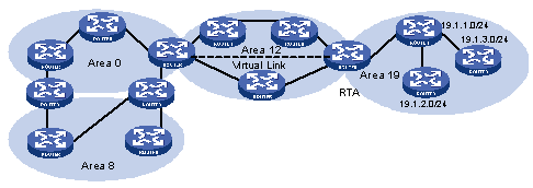
Figure 1-1 Area and route summary
1.1.6 OSPF Features Supported by the S9500 Series
The S9500 series support the following OSPF features:
l Support stub areas: OSPF defines stub areas to decrease the overhead when the routers within the area receive ASE routes.
l Support NSSA: OSPF defines NSSA areas, surmounting the restriction of stub areas on topology. NSSA is the abbreviation of Not-So-Stubby Area.
l Support OSPF Multi-Process: A router runs multiple OSPF processes.
l Share the discovered routing information with other dynamic routing protocols: OSPF currently can import static routes and routes of other dynamic routing protocols such as RIP into the autonomous system of the router, or advertise the routing information discovered by OSPF to other routing protocols.
l Authenticator: OSPF provides clear text authenticator and MD5 encryption authenticator to authenticate packets transmitted between neighboring routers in the same area.
l Flexible configuration for the router port parameter: On the router port, you can configure the following OSPF parameters: output cost, Hello packet interval, retransmission interval, port transmission delay, route precedence, invalid time for adjacent routers, packet authentication mode, packet authenticator, and others.
l Virtual connection: Creates and configures virtual connections.
l Abundant debugging information: OSPF provides abundant debugging information, consequently helping users to diagnose failure
1.2 OSPF GR Overview
Open Shortest Path First (OSPF) is an internal gateway protocol. It is developed by IETF based on link state algorithm. OSPF version 2 (RFC2328) is now commonly used.
Graceful Restart (GR) is designed to keep normal forwarding of the OSPF routing data when abnormal switchover occurs on the switch, so that critical services will not be interrupted.
1.2.1 Working Mechanism of OSPF GR
1. Implementation standard of OSPF GR
RFC3623: Graceful OSPF Restart
IETF drafts:
draft-nguyen-ospf-lls-05;
draft-nguyen-ospf-oob-resync-05;
draft-nguyen-ospf-restart-05;
RFC3623 defines two main principles for GR: the network topology must remain stable and the forwarding tables can be kept when a router is being restarted.
During the GR process, the behaviors of restarters and helpers are defined. A GR process is started with the restarter’s sending a Grace LSA advertisement.
The restarter is a device on which control software restarts. It does not generate LSAs during the GR process. When it receives a self-generated LSA, it will accept and mark this LSA. Route items are not delivered to the forwarding table. The restarter device finds out its state before restart through hello packets on the snooping interface. When all the neighbor relationships are rebuilt or the GR period timeouts, the Restarter devices will exit GR.
The Restarter device will perform standard OSPF re-flooding and routing operation after exiting GR, no matter whether it has finished GR.
A neighbor relationship exists between Helper and GR Restarter. Helper is a peripheral device that assists GR Restarter in synchronizing routing information. The Helper device judges its relationship with the Restarter device when it receives Grace LSA from the Restarter device. When its neighbor state machine is full, and it is not in the GR state, it will enter Helper mode and keep the received Grace LSAs. The Helper routes help the Restarter routes to regain the LSDB information before restart.
3. Work mechanism of IETF drafts
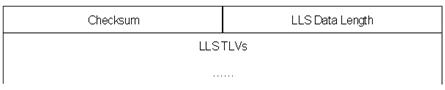
Two primary concepts are defined in the drafts: Link-local Signaling (LLS) which is used to negotiate about OOB capabilities and trigger GR processes and Out-of-band LSDB resynchronization (OOB) which is used to synchronize LSDB.
The L_bit set in a HELLO packet can negotiate about LLS capabilities and notify the peer about its own LLS data. The LR_bit set in the EO_TLV of the LLS data is used to negotiate about the OOB capabilities.
When a protocol is restarted, the protocol will notify the peer that it will be restarted and let the peer keep the neighbor relationship through the RS_bit set in the EO_TLV of a HELLO packet. The R_bit set in a DD packet indicates that this is an OOB process.
The neighbor will keep the neighbor relationship and set the Restartstat-flag after receiving HELLO packets of the RS_bit set.
When both neighbors exit from the OOB process, the standard OSPF algorithm is performed.
& Note:
The GR method on both OSPF neighbors must be the same. Different GR methods cannot perform the GR process successfully. A OSPF process can use only one GR method.
1.2.2 Packet Format of OSPF GR
I. Format of Grace LSA
This LSA is an Opaque-LSA generated by the Restarter. For this LSA, the LS-type is 9, Opaque type is 3 and Opaque ID is 0.
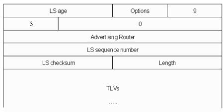
Figure 1-2 Format of Grace LSA
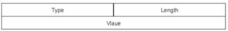
II. Format of TLV
III. Option fields extended by LLS
![]()
Figure 1-4 Option fields with L-bit
IV. Format of LLS data
V. TLV structure: EO_TLV and CA_TLV
1) Format of EO_TLV
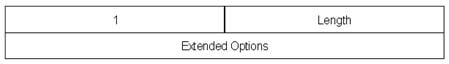
The meaning of each field in EO_TLV:
The type field refers to the type of TLV, and the type of EO_TLV is 1;
The Length field refers to the length of TLV, and the length of EO_TLV is 4;
The Extend Options field is the extend options of OSPF. RS_bit and LR_bit are set in this Option field in OSPF GR. The following figure describes the detailed format:
![]()
Figure 1-7 Format of Extend Option
2) Format of CA_TLV
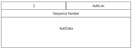
The meaning of each field in the CA_TLV:
The type field refers to the type of CA_TLV, and the type of CA_TLV is 2;
The AuthLen field refers to the length of CA_TLV, and the length of CA_TLV is 20;
The Sequence number and AuthData fields are determined by the OSPF check information.
& Note:
LLS data can be included in only HELLO packets and DD packets. Only one LLS data can be included in a packet. EO_TLV must be included in LLS data. Additionally, CA_TLV must be included in LLS data is OSPF is configured with MD5 check.
VI. Format of DD packets of extended OOB
The R_bit set in a DD packet indicates that this is an OOB process.
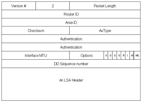
Figure 1-9 Format of DD Packets with R-bit set
1.2.3 OSPF GR Features Supported by CMW
The two GR methods above are supported in the implementation of CMW.
1.3 Configuring OSPF
OSPF configuration needs cooperation among routers: intra-area, area boundary, and AS boundary. If none of OSPF parameters is configured, their default settings apply. In this case, sent and received packets are not authenticated, and an individual interface does not belong to the area of any AS. When reconfiguring a default parameter on one router, make sure that the same change is made on all other involved routers.
In various configurations, you must first enable OSPF, specify the interface and area ID before configuring other functions. But the configuration of the functions related to the interface is not restricted by whether the OSPF is enabled or not. It should be noted that after OSPF is disabled, the OSPF-related interface parameters also become invalid.
OSPF configuration includes:
1) OSPF basic configuration
l Specifying an Interface to Run OSPF
2) Configuration related to OSPF route
l Configuring OSPF to Import Routes of Other Protocols
l Configuring OSPF to Advertise Default Routes
l Configuring OSPF Route Filtering
l Configuring the Route Summary of OSPF
3) Some OSPF configurations
l Setting OSPF Route Preference
l Configuring the Network Type of the OSPF Interface
l Configuring NBMA Neighbors for OSPF
l Setting the Interface Priority for DR Election
l Configuring an Interval Required for Sending LSU Packets
l Configuring the Cost for Sending Packets on an Interface
l Configuring to Fill the MTU Field When an Interface Transmits DD Packets
l Setting a Shortest Path First (SPF) Calculation Interval for OSPF
4) Configurations related to OSPF networking
l Disabling the Interface to Send OSPF Packets
l Configuring OSPF Authentication
l Configuring OSPF Virtual Link
l Configuring Stub Area of OSPF
l Configuring NSSA Area of OSPF
l Setting the Switch for Adjacency State Output
5) Configuration related to specific applications
l Configuring OSPF and Network Management System
6) Others
1.3.1 Configuring a Router ID
A router ID is a 32-bit unsigned integer in IP address format that uniquely identifies a router within an AS. A router ID can be configured manually. If no router ID is configured, the system will select the IP address of an interface automatically. When you do that manually, you must guarantee that the IDs of any two routers in the AS are unique. A common undertaking is to set the router ID to be the IP address of an interface on the router.
Perform the following configuration in system view to configure/remove a router ID:
|
To do... |
Use the command... |
|
Configure a router ID |
router id router-id |
|
Remove the router ID |
undo router id |
If no router ID is configured for an OSPF process, the OSPF process will use the router ID configured with the router id command as its router ID. To ensure stability of OSPF, the user should determine the division of router IDs and manually configure them when planning the network.
1.3.2 Enabling OSPF
Perform the following configuration in system view to enable/disable OSPF:
|
To do... |
Use the command... |
|
Enable OSPF and enter OSPF view |
ospf [ process-id [ router-id router-id | vpn-instance vpn-instance-name]] |
|
Disable one or all OSPF processes |
undo ospf [ process-id ] |
By default, OSPF is disabled.
When enabling OSPF, pay attention to the following points:
l The default OSPF process ID is 1. If no process ID is specified in the command, the default one is adopted.
l If a router is running multiple OSPF processes, you are recommended to use router-id in the command to specify different router IDs for different processes.
l When an OSPF process needs to use a virtual link, you are recommended to use the router-id argument in the above-mentioned command to specify a router ID for the process.
1.3.3 Entering OSPF Area View
OSPF divides an AS into different areas or logical groups of routers.
Perform the following configuration in OSPF view to enter OSPF area view/delete an OSPF area:
|
To do... |
Use the command... |
|
Enter OSPF area view |
area area-id |
|
Delete an OSPF area |
undo area area-id |
The area-id argument identifies an area. It can be a decimal integer in the range of 0 to 4,294,967,295, or in the format of IP address. Regardless of how it is specified, it is displayed in the format of IP address.
Note that when you configure OSPF routers in the same area, you should apply most configuration data to the whole area. Otherwise, the neighboring routers cannot exchange information. This may even block routing information or create routing loops.
1.3.4 Specifying an Interface to Run OSPF
After using the ospf command to enable OSPF in system view, you must specify the network to run OSPF. An ABR router can be in different areas, while a network segment can only belong to an area. That is, you must specify a specific area for each port running OSPF.
Perform the following configuration in OSPF area view to enable/disable OSPF on an interface:
|
To do... |
Use the command... |
|
Specify an interface to run OSPF |
network ip-address ip-mask |
|
Disable OSPF on the interface |
undo network ip-address ip-mask |
The ip-mask argument is IP address wildcard shielded text (similar to the complement of the IP address mask).
1.3.5 Configuring OSPF to Import Routes of Other Protocols
The dynamic routing protocols on the router can share the routing information. As far as OSPF is concerned, the routes discovered by other routing protocols are always processed as the external routes of AS. In the import-route commands, you can specify the route cost type, cost value and tag to overwrite the default route receipt parameters (refer to “Configuring parameters for OSPF to import external routes”).
The OSPF uses the following four types of routes (ordered by priority):
l Intra-area route
l Inter-area route
l External route type 1
l External route type 2
Intra-area and inter-area routes describe the internal AS topology whereas the external routes describe how to select the route to the destinations beyond the AS.
External routes type-1 refers to the calculated cost of the external routes. This cost is the same as the cost of routes within the AS. Also, such route cost and the route cost of the OSPF itself are comparable. That is, cost to reach the external route type 1 = cost to reach the corresponding ASBR from the local router + cost to reach the destination address of the route from the ASBR.
External routes type-2: OSPF assumes that the cost spent from the ASBR to reach the destinations beyond the AS is greatly higher than that spent from within the AS to the ASBR. So in route cost calculation, the former is mainly considered, that is, the cost spent to reach the external route type 2 = cost spent to the destination address of the route from the ASBR. If the two values are equal, then the cost of the router to the corresponding ASBR will be considered.
I. Configure OSPF route redistribution
Perform the following configuration in OSPF view to enable/disable OSPF route redistribution:
|
To do... |
Use the command... |
|
Configure OSPF to redistribute routes from another protocol |
import-route protocol [ cost value | type value | tag value | route-policy route-policy-name ]* |
|
Disable route redistribution from another routing protocol |
undo import-route protocol |
By default, OSPF does not redistribute routing information from other protocols. For a redistributed route, type is 2, cost is 1, and tag is 1 by default.
OSPF can redistribute routes from the following protocols: direct, static, rip, ospf-ase, ospf-nssa, nat, is-is, and bgp, or from other OSPF processes. When RIP redistributes BGP routes, the allow-ibgp keyword can be specified to import IBGP routes.
& Note:
l It is recommended to configure the imported route type, cost and tag for the import-route command simultaneously. Otherwise, the later configuration will overwrite the former configuration.
l After you configured the import-route command on the OSPF router to import external routing information, this OSPF router becomes an ASBR.
II. Configuring the maximum number of imported exterior routes
Perform the following configuration in OSPF view to configure/restore the maximum number of imported exterior routes:
|
To do... |
Use the command... |
|
Configure the maximum number of imported exterior routes |
import-route-limit num |
|
Restore the default value of the maximum number of imported exterior routes |
undo import-route-limit |
By default, the maximum number of imported exterior routes is 20 K.
III. Configuring parameters for OSPF to import external routes
When the OSPF imports the routing information discovered by other routing protocols in the autonomous system, some additional parameters need configuring, such as default route cost and default tag of route distribution. Route tag can be used to identify the protocol-related information. For example, OSPF can use it to identify the AS number when receiving BGP.
Perform the following configuration in OSPF view to configure/restore parameters for OSPF to import external routes:
|
To do... |
Use the command... |
|
Configure the default cost for the OSPF to import external routes |
default cost value |
|
Restore the default cost for the OSPF to import external routes |
undo default cost |
|
Configure the default tag for the OSPF to import external routes |
default tag tag |
|
Restore the default tag for the OSPF to import external routes |
undo default tag |
|
Configure the default type of external routes that OSPF will import |
default type { 1 | 2 } |
|
Restore the default type of the external routes imported by OSPF |
undo default type |
By default, the type of imported route is type-2, the cost is 1 and the tag is 1 for a imported route.
IV. Configuring the default interval and number for OSPF to import external routes
OSPF can import the external routing information and broadcast it to the entire autonomous system. Importing routes too often and importing too many external routes at one time will greatly affect the performance of the device. Therefore it is necessary to specify the default interval and number for the protocol to import external routes.
Perform the following configuration in OSPF view to configure/restore the default interval and number for OSPF to import external routes:
|
To do... |
Use the command... |
|
Configure the default interval for OSPF to import external routes |
default interval seconds |
|
Restore the default interval for OSPF to import external routes |
undo default interval |
|
Specify the upper limit of the routes that OSPF imports at a time |
default limit routes |
|
Restore the default upper limit |
undo default limit |
By default, the interval for importing external routes is 1 second. The upper limit is 1000 at a time.
1.3.6 Configuring OSPF to Advertise Default Routes
By default, there are no default routes in a common OSPF area (either a backbone area or a non-backbone area). Besides, the import-route command cannot be used to import the default route.
Both the default-route-advertise and nssa default-route-advertise commands can be used to advertise default routes. The default-route-advertise command advertises a default Type-5 LSA and the nssa default-route-advertise command advertises a default Type-7 LSA.
Perform the following configuration in OSPF view to configure OSPF to/not to advertise a default Type-5 LSA:
|
To do... |
Use the command... |
|
Advertise a default Type-5 LSA |
default-route-advertise [ always | cost value | type type-value | route-policy route-policy-name ]* |
|
Disable advertising a default Type-5 LSA |
undo default-route-advertise [ always | cost | type | route-policy ]* |
Perform the following configuration in OSPF area view to configure OSPF to/not to advertise a default Type-7 LSA:
|
To do… |
Use the command… |
|
Advertise a default Type-7 LSA |
nssa [ default-route-advertise | no-import-route | no-summary | translate-always ] * |
|
Disable advertising default Type-7 LSAs |
undo nssa |
Note the following when you use the default-route-advertise command:
l If you use the always keyword, the system will generate a default Type-5 LSA regardless of whether the default route is in the routing table or not.
l If the always keyword is not included, the system will generate a default Type-5 LSA only when the default route is available in the routing table.
l The default Type-5 LSA has the same advertising scope as a common Type-5 LSA.
Note the following when you use the nssa default-route-advertise command:
l If the router is the ABR in the NSSA area, the command generates a default Type-7 LSA no matter whether the default route is in the routing table or not.
l If the router is not the ABR in the NSSA area, the command generates a default Type-7 LSA only when the default route exists in the routing table.
l The default Type-7 LSA has the same advertising scope as a common Type-7 LSA.
Because OSPF does not calculate the LSAs it generated during SPF calculation, there is no default route in the OSPF route on this router. To ensure the correct routing information, you should configure to import the default route on the router only connected to the external network.
& Note:
After the default-route-advertise command is configured on the OSPF router, this router becomes an ASBR. For the OSPF router, the default-route-advertise and import-route commands have the similar effect.
1.3.7 Configuring OSPF Route Filtering
Perform the following configuration in OSPF view.
I. Configuring OSPF to filter the received routes
Follow these steps to enable OSPF to/not to filter the received routes:
|
To do... |
Use the command... |
|
Disable filtering the received global routing information |
filter-policy { acl-number | ip-prefix ip-prefix-name | gateway ip-prefix-name } import |
|
Cancel filtering the received global routing information |
undo filter-policy { acl-number | ip-prefix ip-prefix-name | gateway ip-prefix-name } import |
By default, OSPF will not filter the received routing information.
II. Configuring filtering the routes imported to OSPF
Use the filter-policy export command to configure the ASBR router to filter the external routes imported to OSPF. This command is only valid for the ASBR router.
Follow these steps to enable OSPF to/not to filter the imported routes of other routing protocols:
|
To do... |
Use the command... |
|
Enable OSPF to filter the routes advertised by other routing protocols |
filter-policy { acl-number | ip-prefix ip-prefix-name } export [ routing-protocol ] |
|
Disable OSPF to filter the advertised routes by other routing protocols |
undo filter-policy { acl-number | ip-prefix ip-prefix-name } export [ routing-protocol ] |
By default, OSPF does not receive the routes advertised by other routing protocols.
& Note:
l The filter-policy import command only filters the OSPF routes of this process received from the neighbors, and routes that cannot pass the filter will not be added to the routing table.
l The filter-policy export command only takes effect on the routes imported by the import-route command. If you configure the switch with only the filter-policy export command, but without configuring the import-route command to import other external routes (including OSPF routes of different process), then the filter-policy export command does not take effect.
l If the filter-policy export command does not specify which type of route is to be filtered, it takes effect on all routes imported by the local device using the import-route command.
l If no rule is specified in the filter-policy command, all routes are denied by default; if no IP prefix is specified, all routes are permitted by default.
III. Configuring filtering of received Type-3 LSAs
Use the following command to configure route filtering between OSPF areas.
Follow these steps to enable/disable filtering of received Type-3 LSAs:
|
To do... |
Use the command... |
|
Enable an OSPF area to filter received Type-3 LSAs |
filter-policy { acl-number | ip-prefix ip-prefix-name } import |
|
Disable an OSPF area from filtering received Type-3 LSAs |
undo filter-policy { acl-number | ip-prefix ip-prefix-name } import |
By default, the OSPF area does not filter received Type-3 LSAs.
IV. Configuring filtering of Type-3 LSAs advertised to other areas
Follow these steps to enable/disable filtering of Type-3 LSAs advertised to other areas:
|
To do... |
Use the command... |
|
Enable an OSPF area to filter Type-3 LSAs advertised to other areas |
filter-policy { acl-number | ip-prefix ip-prefix-name } export |
|
Disable an OSPF area from filtering Type-3 LSAs advertised to other areas |
undo filter-policy { acl-number | ip-prefix ip-prefix-name } export |
By default, an OSPF area does not filter Type-3 LSAs advertised to other areas.
& Note:
l The filter-policy import/export command filters only locally originated Type-3 LSAs, and does not filter Type-3 LSAs received from neighbors. This command is valid on ABR only.
l If no rule is specified in the filter-policy command, all routes are denied by default.
1.3.8 Configuring the Route Summary of OSPF
I. Configuring the route summary of OSPF area
Route summary means that ABR can aggregate information of the routes of the same prefix and advertise only one route to other areas. An area can be configured with multiple aggregate segments, thereby OSPF can summarize them. When the ABR transmits routing information to other areas, it will generate Sum_net_Lsa (type-3 LSA) per network. If some continuous networks exist in this area, you can use the abr-summary command to summarize these segments into one segment. Thus, the ABR only needs to send an aggregated LSA, and all the LSAs in the range of the aggregate segment specified by the command will not be transmitted separately. This can reduce the LSDB size in other areas.
Once the aggregated segment of a certain network is added to the area, all the internal routes of the IP addresses in the range of the aggregated segment will no longer be separately advertised to other areas. Only the route summary of the whole aggregated network will be advertised. But if the range of the segment is restricted by the keyword not-advertise, the route summary of this segment will not be advertised. This segment is represented by IP address and mask.
Route summary can take effect only when it is configured on ABRs.
Perform the following configuration in OSPF area view to configure/cancel the route summary of OSPF area:
|
To do... |
Use the command... |
|
Configure route summary of OSPF area |
abr-summary ip-address mask [ advertise | not-advertise ] |
|
Cancel route summary of OSPF area |
undo abr-summary ip-address mask |
By default, route summary is disabled on ABRs.
II. Configuring summarization of imported routes by OSPF
OSPF of the S9500 series supports route summary of imported routes.
Perform the following configurations in OSPF view to configure/cancel summarization of imported routes by OSPF:
|
To do... |
Use the command... |
|
Configure summarization of imported routes by OSPF |
asbr-summary ip-address mask [ not-advertise | tag value ] |
|
Remove summarization of routes imported into OSPF |
undo asbr-summary ip-address mask |
By default, summarization of imported routes is disabled.
After the summarization of imported routes is configured, if the local router is an autonomous system border router (ASBR), this command summarizes the imported Type-5 LSAs in the summary address range. When NSSA is configured, this command will also summarize the imported Type-7 LSA in the summary address range.
If the local router works as an area border router (ABR) and a router in the NSSA, this command summarizes Type-5 LSAs transformed from Type-7 LSAs. If the router is not the router in the NSSA, the summarization is disabled.
1.3.9 Setting OSPF Route Preference
Since maybe multiple dynamic routing protocols are running on one router concurrently, the problem of route sharing and selection between various routing protocols occurs. The system sets a preference for each routing protocol, which will be used in tie-breaking in case different protocols discover the same route.
Perform the following configuration in OSPF view to set/restore OSPF route preference:
|
To do... |
Use the command... |
|
Configure a preference for OSPF for comparing with the other routing protocols |
preference [ ase ] preference |
|
Restore the default protocol preference |
undo preference [ ase ] |
By default, the OSPF preference is 10, and that of the imported external routing protocol is 150.
1.3.10 Configuring OSPF Timers
I. Setting the interval for Hello packet transmission
Hello packets are a kind of most frequently used packets, which are periodically sent to the adjacent router for discovering and maintaining the adjacency, and for electing DR and BDR. The user can set the Hello timer.
According to RFC2328, the consistency of Hello intervals between network neighbors should be kept.
Perform the following configuration in interface view to set/resotre the Hello interval:
|
To do... |
Use the command... |
|
Set the hello interval of the interface |
ospf timer hello seconds |
|
Restore the default hello interval of the interface |
undo ospf timer hello |
|
Set the poll interval on the NBMA interface |
ospf timer poll seconds |
|
Restore the default poll interval |
undo ospf timer poll |
By default, p2p and broadcast interfaces send Hello packets every 10 seconds, and p2mp and nbma interfaces send Hello packets every 30 seconds.
II. Setting a dead timer for the neighboring routers
The dead timer of neighboring routers refers to the interval in which a router will regard the neighboring router as dead if no Hello packet is received from it. The user can set a dead timer for the neighboring routers.
Perform the following configuration in interface view to set/restore a dead timer for the neighboring routers:
|
To do... |
Use the command... |
|
Configure a dead timer for the neighboring routers |
ospf timer dead seconds |
|
Restore the default dead interval of the neighboring routers |
undo ospf timer dead |
By default, the dead interval for the neighboring routers of p2p or broadcast interfaces is 40 seconds and that for the neighboring routers of p2mp or nbma interfaces is 120 seconds.
Note that both hello and dead timer will restore to the default values after the user modify the network type.
III. Setting an interval for LSA retransmission between neighboring routers
If a router transmits a Link State Advertisements (LSA) to the peer, it requires the acknowledgement packet from the peer. If it does not receive the acknowledgement packet within the retransmit time, it will retransmit this LSA to the neighbor. The value of retransmit is user-configurable.
Perform the following configuration in interface view to set/restore the interval for LSA retransmission between neighboring routers:
|
To do... |
Use the command... |
|
Configure the interval of LSA retransmission for the neighboring routers |
ospf timer retransmit interval |
|
Restore the default LSA retransmission interval for the neighboring routers |
undo ospf timer retransmit |
By default, the interval for neighboring routers to retransmit LSAs is 5 seconds.
The value of interval should be bigger than the roundtrip value of a packet.
Note that you should not set the LSA retransmission interval too small. Otherwise, unnecessary retransmission will be caused.
1.3.11 Configuring the Network Type of the OSPF Interface
The route calculation of OSPF is based upon the topology of the adjacent network of the local router. Each router describes the topology of its adjacent network and transmits it to all the other routers.
OSPF divides networks into four types by link layer protocol:
l Broadcast: If Ethernet or FDDI is adopted, OSPF defaults the network type to broadcast.
l Non-Broadcast Multi-Access (nbma): If Frame Relay, ATM, HDLC or X.25 is adopted, OSPF defaults the network type to NBMA.
l Point-to-Multipoint (p2mp): OSPF will not default the network type of any link layer protocol to p2mp. A p2mp network is always changed from another type of network. The general undertaking is to change a partially connected NBMA network to p2mp network if the NBMA network is not fully connected.
l Point-to-point (p2p): If PPP, or HDLC is adopted, OSPF defaults the network type to p2p.
NBMA means that a network is non-broadcast and multi-accessible. ATM is a typical example for it. The user can configure the polling interval to specify the interval for sending polling hello packets before the adjacency of the neighboring routers is formed.
Set the network type to NBMA if routers not supporting multicast addresses exist in a broadcast network.
Set the interface type to p2mp if not all the routers are directly accessible on an NBMA network.
Change the interface type to p2p if the router has only one peer on the NBMA network.
The differences between NBMA and p2mp are listed below:
l With OSPF, NBMA refers to the networks that are fully connected, non-broadcast and multi-accessible. However, a p2mp network is not necessarily fully connected.
l DR and BDR are required on an NBMA network but not on p2mp network.
l NBMA is the default network type. For example, if ATM is adopted as the link layer protocol, OSPF defaults the network type on the interface to NBMA, regardless of whether the network is fully connected. p2mp is not the default network type. No link layer protocols are regarded as p2mp. You must change the network type to p2mp by force. The commonest undertaking is to change a partially connected NBMA network to a p2mp network.
l NBMA forwards packets by unicast and requires configuring neighbors manually. p2mp forwards packets by multicast.
Perform the following configuration in interface view to configure/restore the network type for an OSPF interface:
|
To do... |
Use the command... |
|
Configure the network type on the interface |
ospf network-type { broadcast | nbma | p2mp | p2p } |
|
Restore the default network type of the OSPF interface |
undo ospf network-type |
By default, OSPF determines the network type based on the link layer type. After the interface has been configured with a new network type, the original network type of the interface is removed automatically.
1.3.12 Configuring NBMA Neighbors for OSPF
For an NBMA network, some special configurations are required. Since an NBMA interface on the network cannot discover the adjacent router through broadcasting Hello packets, you must manually specify an IP address for the adjacent router for the interface, and specify whether the adjacent router is eligible for election.
Perform the following configuration in OSPF view to configure/remove the NBMA neighbors for OSPF:
|
To do... |
Use the command... |
|
Configure the NBMA neighbors for OSPF |
peer ip-address [ dr-priority dr-priority-number ] |
|
Remove the configured NBMA neighbors |
undo peer ip-address |
By default, the preference for NBMA neighbor is 1.
1.3.13 Setting the Interface Priority for DR Election
On a broadcast or NBMA network, a designated router (DR) and a backup designated router (BDR) must be elected.
The priority of a router interface determines the qualification of the interface in DR election. The router with the priority of 0 cannot be elected as the DR or BDR.
DR is not designated manually. Instead, it is elected by all the routers on the segment. Routers with the priorities larger than 0 in the network are eligible “candidates”. Votes are hello packets. Each router writes the expected DR in the packet and sends it to all the other routers on the segment. If two routers attached to the same segment concurrently declare themselves to be the DR, choose the one with higher priority. If the priorities are the same, choose the one with greater router ID. If the priority of a router is 0, it will not be elected as DR or BDR.
If DR fails due to some faults, the routers on the network must elect a new DR and synchronize with the new DR. The process will take a relatively long time, during which, the route calculation is incorrect. In order to speed up this process, OSPF puts forward the concept of BDR. In fact, BDR is a backup for DR. DR and BDR are elected in the meantime. The adjacencies are also established between the BDR and all the routers on the segment, and routing information is also exchanged between them. When the DR fails, the BDR will become the DR instantly. Since no re-election is needed and the adjacencies have already been established, the process is very short. But in this case, a new BDR should be elected. Although it will also take a quite long period of time, it will not exert any influence upon the route calculation.
Note the following:
l The DR on the network is not necessarily the router with the highest priority. Likewise, the BDR is not necessarily the router with the second highest priority. If a new router is added after DR and BDR election, it is impossible for the router to become the DR even if it has the highest priority.
l DR is based on the router interface in a certain segment. Maybe a router is a DR on one interface, but can be a BDR or DROther on another interface.
l DR election is only required for the broadcast or NBMA interfaces. For the p2p or p2mp interfaces, DR election is not required.
Perform the following configuration in interface view to set/restore the interface priority for DR election:
|
To do... |
Use the command... |
|
Configure the interface with a priority for DR election |
ospf dr-priority priority-num |
|
Restore the default interface priority |
undo ospf dr-priority |
By default, the priority of the interface is 1 in the DR election.
Use the ospf dr-priority and peer commands to set priorities with different usages:
l Use the ospf dr-priority command to set priority for DR selection.
l The priority you use the peer command to set indicates whether the adjacent router is eligible for election. If you specify the priority as 0 during neighbor configuration, the local router considers that this neighbor is not eligible for election, thus sending no Hello packets to this neighbor. This configuration can reduce the Hello packets on the network during DR and BDR selection. However, if the local router is DR or BDR, this router can also send Hello packets to the neighbor with priority 0 to establish adjacency relations.
1.3.14 Configuring an Interval Required for Sending LSU Packets
Trans-delay seconds should be added to the aging time of the LSA in an LSU packet. Setting the parameter like this mainly considers the time duration that the interface requires for transmitting a packet.
The user can configure the interval of sending LSU message. Obviously, more attention should be paid to this item over low speed networks.
Perform the following configuration in interface view to configure/restore an interval required for sending LSU packets:
|
To do... |
Use the command... |
|
Configure an interval for sending LSU packets |
ospf trans-delay seconds |
|
Restore the default interval for sending LSU packets |
undo ospf trans-delay |
By default, the LSU packets are transmitted per second.
1.3.15 Configuring the Cost for Sending Packets on an Interface
The user can control the network traffic by configuring different packet sending costs for different interfaces.
Perform the following configuration in interface view to configure/restore the cost for sending packets on an interface:
|
To do... |
Use the command... |
|
Configure the cost for sending packets on an interface |
ospf cost value |
|
Restore the default cost for packet transmission on the interface |
undo ospf cost |
For S9500 series, the default cost for running OSPF on the VLAN interface is 10.
1.3.16 Configuring to Fill the MTU Field When an Interface Transmits DD Packets
OSPF-running routers use Database Description (DD) packets to describe their own LSDBs during LSDB synchronization.
You can manually specify an interface to fill in the MTU field in a DD packet when it transmits the packet. The MTU should be set to the real MTU on the interface.
Perform the following configuration in interface view to configure whether the MTU field will be filled in when an interface transmits DD packets:
|
To do... |
Use the command... |
|
Enable an interface to fill in the MTU field when transmitting DD packets |
ospf mtu-enable |
|
Disable the interface to fill the MTU field when transmitting DD packets |
undo ospf mtu-enable |
By default, the interface does not fill in the MTU field when transmitting DD packets. In other words, MTU in the DD packets is 0.
1.3.17 Setting a Shortest Path First (SPF) Calculation Interval for OSPF
Whenever the LSDB of OSPF takes changes, the shortest path requires recalculation. Calculating the shortest path upon change will consume enormous resources as well as affect the operation efficiency of the router. Adjusting the SPF calculation interval, however, can restrain the resource consumption due to frequent network changes.
Perform the following configuration in OSPF view to set/restore the SPF calculation interval:
|
To do... |
Use the command... |
|
Set the SPF calculation interval |
spf-schedule-interval seconds |
|
Restore the SPF calculation interval |
undo spf-schedule-interval seconds |
By default, the interval of SPF recalculation is five seconds.
1.3.18 Disabling the Interface to Send OSPF Packets
To prevent OSPF routing information from being acquired by the routers on a certain network, use the silent-interface command to disable the interface to transmit OSPF packets.
Perform the following configuration in OSPF view to enable/disable OSPF packet transmission:
|
To do... |
Use the command... |
|
Disable the interface from sending OSPF packets |
silent-interface { default | vlan-interface vlan-interface-number } |
|
Enable the interface to send OSPF packets |
undo silent-interface { default | vlan-interface vlan-interface-number } |
By default, all interfaces are allowed to transmit and receive OSPF packets.
After an OSPF interface is set to be in silent status, the interface can still advertise its direct route. However, the OSPF hello packets of the interface will be blocked, and no neighboring relationship can be established on the interface. Thereby, the capability for OSPF to adapt to the networking can be enhanced, which will hence reduce the consumption of system resources. On a switch, this command can disable/enable the specified VLAN interface to send OSPF packets.
1.3.19 Configuring OSPF Authentication
I. Configuring the OSPF Area to Support Packet Authentication
All the routers in one area must use the same authentication mode (no authentication, simple text authentication or MD5 cipher text authentication). If the mode of supporting authentication is configured, all routers on the same segment must use the same authentication key. To configure a simple text authentication key, use the authentication-mode simple command. Use the authentication-mode md5 command to configure the MD5 cipher text authentication key if the area is configured to support MD5 cipher text authentication mode.
Perform the following configuration in OSPF area view to enable/disable packet authentication in the OSPF area:
|
To do... |
Use the command... |
|
Configure the area to support authentication type |
authentication-mode { simple | md5 } |
|
Cancel the configured authentication mode |
undo authentication-mode |
By default, the area does not support packet authentication.
II. Configuring OSPF packet authentication
OSPF supports simple authentication or MD5 authentication between neighboring routers.
The authentication type configured on an interface takes effect only after the area to which the interface belongs is configured with the corresponding authentication type.
Perform the following configuration in interface view to enable/disable OSPF packet authentication:
|
To do... |
Use the command... |
|
Specify a password for OSPF simple text authentication on the interface |
ospf authentication-mode simple password |
|
Cancel simple authentication on the interface |
undo ospf authentication-mode simple |
|
Specify the interface to use MD5 authentication |
ospf authentication-mode md5 key-id key |
|
Disable the interface to use MD5 authentication |
undo ospf authentication-mode md5 |
By default, the interface is not configured with either simple authentication or MD5 authentication.
1.3.20 Configuring OSPF Virtual Link
According to RFC2328, after the area partition of OSPF, not all the areas are equal. In which, an area is different from all the other areas. Its Area-id is 0.0.0.0 and it is usually called the backbone Area. The OSPF routes between non-backbone areas are updated with the help of the backbone area. OSPF stipulates that all the non-backbone areas should maintain the connectivity with the backbone area. That is, at least one interface on the ABR should fall into the area 0.0.0.0. If an area does not have a direct physical link with the backbone area 0.0.0.0, a virtual link must be created.
If the physical connectivity cannot be ensured due to the network topology restriction, a virtual link can satisfy this requirement. The virtual link refers to a logic channel set up through the area of a non-backbone internal route between two ABRs. Both ends of the logic channel should be ABRs and the connection can take effect only when both ends are configured. The virtual link is identified by the ID of the remote router. The area, which provides the ends of the virtual link with a non-backbone area internal route, is called the transit area. The ID of the transit area should be specified during configuration.
The virtual link is activated after the route passing through the transit area is calculated, which is equivalent to a p2p connection between two ends. Therefore, similar to the physical interfaces, you can also configure various interface parameters on this link, such as hello timer.
The "logic channel" means that the routers running OSPF between two ABRs only take the role of packet forwarding (the destination addresses of the protocol packets are not these routers, so these packets are transparent to them and the routers forward them as common IP packets). The routing information is directly transmitted between the two ABRs. The routing information herein refers to the Type-3 LSAs generated by the ABRs, for which the synchronization mode of the routers in the area will not be changed.
Perform the following configuration in OSPF area view to create/remove an OSPF virtual link:
|
To do... |
Use the command... |
|
Create and configure a virtual link |
vlink-peer router-id [ hello seconds | retransmit seconds | trans-delay seconds | dead seconds | simple password | md5 keyid key ]* |
|
Remove the created virtual link |
undo vlink-peer router-id |
By default, the value of hello seconds is 10 seconds, the value of retransmit seconds is 5 seconds, the value of trans-delay seconds is 1 second, and the value of dead seconds is 40 seconds.
1.3.21 Configuring Stub Area of OSPF
Stub areas are some special areas, in which the ABRs do not propagate the learned external routes of the AS.
The stub area is an optional configuration attribute, but not every area conforms to the configuration condition. Generally, stub areas, located at the AS boundaries, are those non-backbone areas with only one ABR. Even if this area has multiple ABRs, no virtual links are established between these ABRs.
To ensure that the routes to the destinations outside the AS are still reachable, the ABR in this area will generate a default route (0.0.0.0) and advertise it to the non-ABR routers in the area.
Pay attention to the following items when configuring a stub area:
l The backbone area cannot be configured to be the stub area and the virtual link cannot pass through the stub area.
l If you want to configure an area to be the stub area, then all the routers in this area should be configured with this attribute.
l No ASBR can exist in a stub area. In other words, the external routes of the AS cannot be propagated in the stub area.
Perform the following configuration in OSPF area view to configure/remove stub area of OSPF:
|
To do... |
Use the command... |
|
Configure an area to be the stub area |
stub [ no-summary ] |
|
Remove the configured stub area |
undo stub |
|
Configure the cost of the default route transmitted by OSPF to the stub area |
default-cost value |
|
Remove the cost of the default route to the stub area |
undo default-cost |
By default, the stub area is not configured, and the cost of the default route to the stub area is 1.
1.3.22 Configuring NSSA Area of OSPF
RFC3101 introduced a new type of area called NSSA area, and a new type of LSA called NSSA LSA (or Type-7 LSA).
NSSA areas are virtually variations of Stub areas. They are similar in many ways. Neither of them generates or imports AS-External-LSA (namely Type-5 LSA), and both of them can generate and import Type-7 LSA. Type-7 LSA is generated by ASBR of NSSA area, which can only be advertised in NSSA area. When Type-7 LSA reaches ABR of NSSA, the ABR with a neighbor in the FULL state in the backbone area will select whether to transform Type-7 LSA into AS-External-LSA so as to advertise to other areas.
For example, in the network below, the AS running OSPF comprises three areas: Area 1, Area 2 and Area 0. Among them, Area 0 is the backbone area. Also, there are other two ASs respectively running RIP. Area 1 is defined as an NSSA area. After RIP routes of the Area 1 are propagated to the NSSA ASBR, the NSSA ASBR will generate type-7 LSAs which will be propagated in Area 1. When the type-7 LSAs reach the NSSA ABR, the NSSA ABR will transform it into type-5 LSA, which will be propagated to Area 0 and Area 2. On the other hand, RIP routes of the AS running RIP will be transformed into type-5 LSAs that will be propagated in the OSPF AS. However, the type-5 LSAs will not reach Area 1 because Area 1 is an NSSA. NSSAs and stub areas have the same approach in this aspect.
Similar to a stub area, the NSSA cannot be configured with virtual links.

Perform the following configuration in OSPF area view to configure/cancel NSSA of OSPF:
|
To do... |
Use the command... |
|
Configure an area to be the NSSA area |
nssa [ default-route-advertise | no-import-route | no-summary | translate-always ] * |
|
Cancel the configured NSSA |
undo nssa |
|
Configure the default cost value of the route to the NSSA |
default-cost cost |
|
Restore the default cost value of the route to the NSSA area |
undo default-cost |
All the routers connected to the NSSA should use the nssa command to configure the area with the NSSA attribute.
The keyword default-route-advertise is used to generate default type-7 LSAs. When default-route-advertise is configured, a default type-7 LSA route will be generated on the ABR, even though no default route 0.0.0.0 is in the routing table. On an ASBR, however, a default type-7 LSA route can be generated only if the default route 0.0.0.0 is in the routing table.
Executing the keyword no-import-route on the ASBR will prevent the external routes that OSPF imported through the import-route command from being advertised to the NSSA. Generally, if an NSSA router is both ASBR and ABR, this keyword will be used.
Use the translate-always keyword to specify the NSSA ABR as the translator. If a neighbor in the FULL state exists in the backbone area, the translator will unconditionally translate the LSAs (whose P-BIT is true and forwarding address is not 0.0.0.0) corresponding to the Type-7 routes calculated locally into Type-5 LSAs.
The keyword default-cost is used on the ABR attached to the NSSA. Using this command, you can configure the default route cost on the ABR to NSSA.
By default, the NSSA is not configured, and the cost of the default route to the NSSA is 1.
1.3.23 Setting the Switch for Adjacency State Output
When the switch for adjacency state output is enabled, the OSPF adjacency state changes will be output to the configuration terminal until the switch for adjacency state output is disabled.
Perform the following configuration in OSPF view to set the switch for adjacency state output:
|
To do... |
Use the command... |
Description |
|
Enter system view |
system-view |
— |
|
Enter OSPF view |
ospf [ process-id [ router-id router-id | vpn-instance vpn-instance-name] ] |
Required |
|
Set the switch for adjacency state output |
log-peer-change |
Required The OSPF adjacency state changes are not reported by default |
1.3.24 Configuring OSPF and Network Management System
I. Configuring OSPF MIB binding
After multiple OSPF processes are enabled, you can configure to which OSPF process MIB is bound.
Perform the following configuration in system view to configure/restore OSPF MIB binding:
|
To do... |
Use the command... |
|
Configure OSPF MIB binding |
ospf mib-binding process-id |
|
Restore the default OSPF MIB binding |
undo ospf mib-binding |
By default, MIB is bound to the first enabled OSPF process.
II. Configuring OSPF TRAP
The OSPF Trap function enables the switch to send multiple types of SNMP Trap packets in case of OSPF process exceptions. In addition, you can specify an OSPF process ID so that this functions works only on that process. If no process ID is specified, this function works on all OSPF processes.
Perform the following configuration in system view to enable/disable OSPF TRAP function:
|
To do... |
Use the command... |
|
Enable OSPF TRAP function |
snmp-agent trap enable ospf [ process-id ] [ ifstatechange | virifstatechange | nbrstatechange | virnbrstatechange | ifcfgerror | virifcfgerror | ifauthfail | virifauthfail | ifrxbadpkt | virifrxbadpkt | iftxretransmit | viriftxretransmit | originatelsa | maxagelsa | lsdboverflow | lsdbapproachoverflow ] |
|
Disable OSPF TRAP function |
undo snmp-agent trap enable ospf [ process-id ] [ ifstatechange | virifstatechange | nbrstatechange | virnbrstatechange | ifcfgerror | virifcfgerror | ifauthfail | virifauthfail | ifrxbadpkt | virifrxbadpkt | iftxretransmit | viriftxretransmit | originatelsa | maxagelsa | lsdboverflow | lsdbapproachoverflow ] |
By default, OSPF TRAP function is disabled. That is, the switch does not send TRAP packets when any OSPF process is abnormal.
1.3.25 Configuring OSPF GR
I. Configuring GR method as RFC3623
Follow these steps to configure OSPF GR:
|
To do... |
Use the command... |
Description |
|
Enter system view |
system-view |
— |
|
Enter OSPF view |
ospf [ process-id [ [ router-id router-id ] vpn-instance vpn-instance-name ] ] |
— |
|
Configure GR |
graceful-restart [ value ] |
Required The time is 120 s by default |
II. Configuring GR method as IETF drafts
Follow these steps to configure OSPF GR:
|
To do... |
Use the command... |
Description |
|
Enter system view |
system-view |
— |
|
Enter OSPF view |
ospf [ process-id [ [ router-id router-id ] vpn-instance vpn-instance-name ] ] |
— |
|
Configure GR |
graceful-restart compatible |
Required |
1.3.26 Resetting the OSPF Process
If the undo ospf command is executed on a router and then the ospf command is used to restart the OSPF process, the previous OSPF configuration will lose. With the reset ospf command, you can restart the OSPF process without losing the previous OSPF configuration.
Perform the following configuration in user view to reset OSPF processes:
|
To do... |
Use the command... |
|
Reset one or all OSPF processes |
reset ospf [ statistics ] { all | process-id } |
Resetting the OSPF process can immediately clear invalid LSAs, and make the modified router ID effective or the DR and BDR are re-elected.
1.4 Displaying and Debugging OSPF
|
To do... |
Use the command... |
|
Display the brief information of the OSPF routing process |
display ospf [ process-id ] brief |
|
Display OSPF statistics |
display ospf [ process-id ] cumulative |
|
Display LSDB information of OSPF |
display ospf [ process-id ] [ area-id ] lsdb [ brief | [ asbr | ase | network | nssa | router | summary ] [ ip-address ] [ originate-router ip-address | self-originate ] [ verbose ] ] |
|
Display OSPF peer information |
display ospf [ process-id ] peer [ brief ] |
|
Display OSPF next hop information |
display ospf [ process-id ] nexthop |
|
Display OSPF routing table |
display ospf [ process-id ] routing |
|
Display OSPF virtual links |
display ospf [ process-id ] vlink |
|
Display OSPF request list |
display ospf [ process-id ] request-queue |
|
Display OSPF retransmission list |
display ospf [ process-id ] retrans-queue |
|
Display the information of OSPF ABR and ASBR |
display ospf [ process-id ] abr-asbr |
|
View OSPF inter-area route summarization information |
display ospf [ process-id ] abr-summary |
|
Display the summary information of OSPF imported routes |
display ospf [ process-id ] asbr-summary [ ip-address mask ] |
|
Display OSPF interface information |
display ospf [ process-id ] interface |
|
Display OSPF errors |
display ospf [ process-id ] error |
|
Display OSPF Graceful Restart information |
display ospf [ process-id ] graceful-restart status |
|
Display the state of the global OSPF debugging switches and the state of the debugging switches for each process |
|
|
Enable OSPF packet debugging |
debugging ospf packet [ ack | dd | hello | interface interface-type interface-number | request I update ] |
|
Disable OSPF packet debugging |
undo debugging ospf packet [ ack | dd | hello | interface interface-type interface-number | request I update ] |
|
Enable OSPF event debugging |
debugging ospf event |
|
Disable OSPF event debugging |
undo debugging ospf event |
|
Enable OSPF LSA packet debugging |
debugging ospf lsa-originate |
|
Disable OSPF LSA packet debugging |
undo debugging ospf lsa-originate |
|
Enable SPF debugging of OSPF |
debugging ospf spf |
|
Disable SPF debugging of OSPF |
undo debugging ospf spf |
1.5 OSPF Configuration Example
1.5.1 Configuring DR Election Based on OSPF Priority
I. Network requirements
Four the S9500 series switches, Switch A, Switch B, Switch C and Switch D, which can perform the router functions and run OSPF, are located on the same segment, as shown in the following figure.
Configure Switch A and Switch C as DR and BDR respectively. The priority of Switch A is 100, which is the highest on the network, so it is elected as the DR. Switch C has the second highest priority, that is, 2, so it is elected as the BDR. The priority of Switch B is 0, which means that it cannot be elected as the DR. Switch D does not have a priority, which takes 1 by default.
II. Network diagram
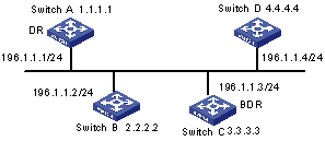
Figure 1-11 Network diagram for configuring DR election based on OSPF priority
III. Configuration procedure
# Configure Switch A.
[Switch A] interface Vlan-interface 1
[Switch A-Vlan-interface1] ip address 196.1.1.1 255.255.255.0
[Switch A-Vlan-interface1] ospf dr-priority 100
[Switch A] router id 1.1.1.1
[Switch A] ospf
[Switch A-ospf-1] area 0
[Switch A-ospf-1-area-0.0.0.0] network 196.1.1.0 0.0.0.255
# Configure Switch B.
[Switch B] interface Vlan-interface 1
[Switch B-Vlan-interface1] ip address 196.1.1.2 255.255.255.0
[Switch B-Vlan-interface1] ospf dr-priority 0
[Switch B] router id 2.2.2.2
[Switch B] ospf
[Switch B-ospf-1] area 0
[Switch B-ospf-1-area-0.0.0.0] network 196.1.1.0 0.0.0.255
# Configure Switch C.
[Switch C] interface Vlan-interface 1
[Switch C-Vlan-interface1] ip address 196.1.1.3 255.255.255.0
[Switch C-Vlan-interface1] ospf dr-priority 2
[Switch C] router id 3.3.3.3
[Switch C] ospf
[Switch C-ospf-1] area 0
[Switch C-ospf-1-area-0.0.0.0] network 196.1.1.0 0.0.0.255
# Configure Switch D.
[Switch D] interface Vlan-interface 1
[Switch D-Vlan-interface1] ip address 196.1.1.4 255.255.255.0
[Switch D] router id 4.4.4.4
[Switch D] ospf
[Switch D-ospf-1] area 0
[Switch D-ospf-1-area-0.0.0.0] network 196.1.1.0 0.0.0.255
On Switch A, execute the display ospf peer command to display the OSPF peers. Note that Switch A has three peers.
The state of each peer is full, which means that adjacency is set up between Switch A and each peer. (Switch A and Switch C should set up adjacencies with all the routers on the network for them to be DR and BDR on the network respectively.) Switch A is DR, while Switch C is BDR on the network. And all the other neighbors are DR others (which means that they are neither DRs nor BDRs).
# Change the priority of Switch B to 200.
[Switch B-Vlan-interface2000] ospf dr-priority 200
On Switch A, execute the display ospf peer command to show its OSPF neighbors. Note the priority of Switch B has changed to 200, but it is still not the DR.
Only when the current DR is offline will the DR be changed. Shut down Switch A, and execute the display ospf peer command on Switch D to display its neighbors. Note that the original BDR (Switch C) becomes the DR, and Switch B is BDR now.
If all Switches on the network are removed and added back again, Switch B will be elected as the DR (with the priority of 200), and Switch A becomes the BDR (with a priority of 100). To switch off and restart all of the switches will bring about a new round of DR/BDR selection.
1.5.2 Configuring OSPF Virtual Link
I. Network requirements
In Figure 1-12, Area 2 and Area 0 are not directly connected. Area 1 is required to be taken as a transit area for connecting Area 2 and Area 0. Configure a virtual link between Switch B and Switch C in Area 1.
II. Network diagram
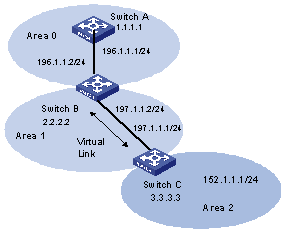
Figure 1-12 Network diagram for OSPF virtual link configuration
III. Configuration procedure
# Configure Switch A.
[Switch A] interface Vlan-interface 1
[Switch A-Vlan-interface1] ip address 196.1.1.1 255.255.255.0
[Switch A] router id 1.1.1.1
[Switch A] ospf
[Switch A-ospf-1] area 0
[Switch A-ospf-1-area-0.0.0.0] network 196.1.1.0 0.0.0.255
# Configure Switch B.
[Switch B] interface vlan-interface 7
[Switch B-Vlan-interface7] ip address 196.1.1.2 255.255.255.0
[Switch B] interface vlan-interface 8
[Switch B-Vlan-interface8] ip address 197.1.1.2 255.255.255.0
[Switch B] router id 2.2.2.2
[Switch B] ospf
[Switch B-ospf-1] area 0
[Switch B-ospf-1-area-0.0.0.0] network 196.1.1.0 0.0.0.255
[Switch B-ospf-1-area-0.0.0.0] quit
[Switch B-ospf-1] area 1
[Switch B-ospf-1-area-0.0.0.1] network 197.1.1.0 0.0.0.255
[Switch B-ospf-1-area-0.0.0.1] vlink-peer 3.3.3.3
# Configure Switch C.
[Switch C] interface Vlan-interface 1
[Switch C-Vlan-interface1] ip address 152.1.1.1 255.255.255.0
[Switch C] interface Vlan-interface 2
[Switch C-Vlan-interface2] ip address 197.1.1.1 255.255.255.0
[Switch C] router id 3.3.3.3
[Switch C] ospf
[Switch C-ospf-1] area 1
[Switch C-ospf-1-area-0.0.0.1] network 197.1.1.0 0.0.0.255
[Switch C-ospf-1-area-0.0.0.1] vlink-peer 2.2.2.2
[Switch C-ospf-1-area-0.0.0.1] quit
[Switch C-ospf-1] area 2
[Switch C-ospf-1-area-0.0.0.2] network 152.1.1.0 0.0.0.255
1.5.3 OSPF GR Configuration Example
I. Network requirements
l For the GR-enabled switch, the GR method must be configured in the view of the corresponding process. Additionally, the Neighbor State Machine (NSM) must be in the FULL state.
l Three switches S9500 A, S9500 B and S9500 C are connected adjacently with each other. S9500 A serves as the Restarter, and S9500 B and S8500 C serve as the Helper.
II. Network diagram
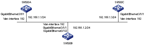
III. Configuration procedure
# Configure the switch S9500 A.
<S9500A> system-view
[S9500A] vlan 192
[S9500A-vlan192] port GigabitEthernet 3/1/1
[S9500A-vlan192] interface vlan 192
[S9500A-Vlan-interface192] ip address 192.168.1.1 24
[S9500A-Vlan-interface192] quit
[S9500A] ospf 1
[S9500A-ospf-1] graceful-restart 180
[S9500A-ospf-1] area 0
[S9500A-ospf-1-area-0.0.0.0] network 192.168.1.0 0.0.0.255
# Configure the switch S9500 B.
<S9500B> system-view
[S9500B] vlan 192
[S9500B-vlan192] port GigabitEthernet 3/1/1
[S9500B-vlan192] interface vlan 192
[S9500B-Vlan-interface192] ip address 192.168.1.2 24
[S9500B-Vlan-interface192] quit
[S9500B] interface GigabitEthernet 3/1/2
[S9500B-GigabitEthernet3/1/2] port access vlan 192
[S9500B-GigabitEthernet3/1/2] quit
[S9500B] ospf 1
[S9500B-ospf-1] graceful-restart 180
[S9500B-ospf-1] area 0
[S9500B-ospf-1-area-0.0.0.0] network 192.168.1.0 0.0.0.255
# Configure the switch S9500C.
<S9500C> system-view
[S9500C] vlan 192
[S9500C-vlan192] port GigabitEthernet 3/1/1
[S9500C-vlan192] interface vlan 192
[S9500C-Vlan-interface192] ip address 192.168.1.3 24
[S9500C-Vlan-interface192] quit
[S9500C] ospf 1
[S9500C-ospf-1] graceful-restart 180
[S9500C-ospf-1] area 0
[S9500C-ospf-1-area-0.0.0.0] network 192.168.1.0 0.0.0.255
1.6 Troubleshooting OSPF Configuration
Symptom 1: OSPF has been configured in accordance with the earlier-mentioned steps, but OSPF on the router cannot run normally.
Solution: Check according to the following procedure.
Local troubleshooting: Check whether the protocol between two directly connected routers is in normal operation. The normal sign is the peer state machine between the two routers reaches the FULL state. (Note: On a broadcast or NBMA network, if the interfaces for two routers are in DROther state, the peer state machines for the two routers are in 2-way state, instead of FULL state. The peer state machine between DR/BDR and all the other routers is in FULL state.
l Execute the display ospf peer command to view peers.
l Execute the display ospf interface command to view OSPF information on the interface.
l Check whether the physical connections and the lower layer protocol operate normally. You can execute the ping command to test. If the local router cannot ping the peer router, it indicates that faults have occurred to the physical link and the lower layer protocol.
l If the physical link and the lower layer protocol are normal, check the OSPF parameters configured on the interface. The parameters should be the same parameters configured on the router adjacent to the interface. The same area ID should be used, and the networks and the masks should also be consistent. (The p2p or virtually linked segment can have different segments and masks.)
l Ensure that the dead timer on the same interface is at least four times the value of the Hello timer.
l If the network type is NBMA, the peer must be manually specified, using the peer ip-address command.
l If the network type is broadcast or NBMA, there must be at least one interface with a priority greater than zero.
l If an area is set as the stub area, to which the routers are connected. The area on these routers must be also set as the stub area.
l The same interface type should be adopted for the neighboring routers.
l If more than two areas are configured, at least one area should be configured as the backbone area (that is to say, the area ID is 0).
l Ensure that the backbone area is connected to all other areas.
l The virtual links do not pass through the stub area.
Global troubleshooting: If OSPF cannot discover the remote routes yet in the case that the above steps are correctly performed, proceed to check the following configurations.
l If more than two areas are configured on a router, at least one area should be configured as the backbone area.
As shown in Figure 1-14: RTA and RTD are configured to belong to only one area, whereas RTB (Area0 and Area1) and RTC (Area1 and Area 2) are configured to belong to two areas. In which, RTB also belongs to area0, which is compliant with the requirement. However, none of the areas to which RTC belongs is Area0. Therefore, a virtual link should be set up between RTC and RTB. Ensure that Area2 and Area0 (backbone area) is connected.
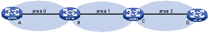
l The backbone area (Area 0) cannot be configured as the stub area and the virtual link cannot pass through the stub area. That is, if a virtual link has been set up between RTB and RTC, neither Area1 nor Area0 can be configured as a stub area. In the figure above, only Area 2 can be configured as the stub area.
l Routers in the stub area cannot receive external routes.
l The backbone area must guarantee the connectivity of all nodes.