- Table of Contents
-
- H3C S6800 & S6860 & S6861 Switches Configuration Examples-Release 27xx-6W100
- 01-Login Management Configuration Examples
- 02-RBAC Configuration Examples
- 03-Software Upgrade Examples
- 04-ISSU Configuration Examples
- 05-Software Patching Examples
- 06-Ethernet Link Aggregation Configuration Examples
- 07-Port Isolation Configuration Examples
- 08-Spanning Tree Configuration Examples
- 09-VLAN Configuration Examples
- 10-VLAN Tagging Configuration Examples
- 11-PBB Configuration Examples
- 12-DHCP Snooping Configuration Examples
- 13-Cross-Subnet Dynamic IP Address Allocation Configuration Examples
- 14-IPv6 over IPv4 Manual Tunneling with OSPFv3 Configuration Examples
- 15-ISATAP Tunnel and 6to4 Tunnel Configuration Examples
- 16-IPv6 over IPv4 GRE Tunnel Configuration Examples
- 17-GRE with OSPF Configuration Examples
- 18-OSPF Configuration Examples
- 19-IS-IS Configuration Examples
- 20-BGP Configuration Examples
- 21-Policy-Based Routing Configuration Examples
- 22-OSPFv3 Configuration Examples
- 23-IPv6 IS-IS Configuration Examples
- 24-Routing Policy Configuration Examples
- 25-IGMP Snooping Configuration Examples
- 26-IGMP Configuration Examples
- 27-BIDIR-PIM Configuration Examples
- 28-Multicast VPN Configuration Examples
- 29-MLD Snooping Configuration Examples
- 30-IPv6 Multicast VLAN Configuration Examples
- 31-Basic MPLS Configuration Examples
- 32-MPLS L3VPN Configuration Examples
- 33-ACL Configuration Examples
- 34-Control Plane-Based QoS Policy Configuration Examples
- 35-Traffic Policing Configuration Examples
- 36-GTS and Rate Limiting Configuration Examples
- 37-Priority Mapping and Queue Scheduling Configuration Examples
- 38-Traffic Filtering Configuration Examples
- 39-AAA Configuration Examples
- 40-Port Security Configuration Examples
- 41-Portal Configuration Examples
- 42-SSH Configuration Examples
- 43-IP Source Guard Configuration Examples
- 44-Ethernet OAM Configuration Examples
- 45-CFD Configuration Examples
- 46-DLDP Configuration Examples
- 47-VRRP Configuration Examples
- 48-BFD Configuration Examples
- 49-NTP Configuration Examples
- 50-SNMP Configuration Examples
- 51-NQA Configuration Examples
- 52-Mirroring Configuration Examples
- 53-sFlow Configuration Examples
- 54-FCoE Configuration Examples
- 55-SPBM Configuration Examples
- 56-OpenFlow Configuration Examples
- 57-MAC Address Table Configuration Examples
- 58-Static Multicast MAC Address Entry Configuration Examples
- 59-IP Unnumbered Configuration Examples
- 60-MVRP Configuration Examples
- 61-MCE Configuration Examples
- 62-Congestion Avoidance and Queue Scheduling Configuration Examples
- 63-Attack Protection Configuration Examples
- 64-Smart Link Configuration Examples
- 65-RRPP Configuration Examples
- 66-BGP Route Selection Configuration Examples
- 67-IS-IS Route Summarization Configuration Examples
- 68-IRF Configuration Examples
- 69-MPLS OAM Configuration Examples
- 70-MPLS TE Configuration Examples
- 71-GRE with VPN Configuration Examples
- 72-VXLAN Configuration Examples
- 73-DRNI Configuration Examples
- 74-IRF 3.1 Configuration Examples
- 75-DRNI and EVPN Configuration Examples
- 76-EVPN-DCI over an MPLS L3VPN Network Configuration Examples
- 77-VCF Fabric Configuration Examples
- 78-PTP Configuration Examples
- 79-S-MLAG Configuration Examples
- 80-MPLS SR Configuration Examples
- 81-Puppet Configuration Examples
- Related Documents
-
| Title | Size | Download |
|---|---|---|
| 77-VCF Fabric Configuration Examples | 123.50 KB |
|
|
|
H3C S6800 & S6860 & S6861 Switches |
|
VCF Fabric Configuration Examples |
|
|
Copyright © 2019 New H3C Technologies Co., Ltd. All rights reserved.
No part of this manual may be reproduced or transmitted in any form or by any means without prior written consent of New H3C Technologies Co., Ltd.
Except for the trademarks of New H3C Technologies Co., Ltd., any trademarks that may be mentioned in this document are the property of their respective owners.
The information in this document is subject to change without notice.
Contents
Example: Configuring automated VCF fabric deployment
Applicable hardware and software versions
Configuring the director server
Deploying the underlay network
Introduction
This document provides VCF fabric configuration examples.
Prerequisites
The configuration examples in this document were created and verified in a lab environment, and all the devices were started with the factory default configuration. When you are working on a live network, make sure you understand the potential impact of every command on your network.
This document assumes that you have basic knowledge of VCF fabric.
Example: Configuring automated VCF fabric deployment
Network configuration
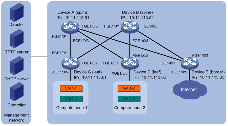
As shown in Figure 1, on a VXLAN network with distributed IP gateways, Device A and Device B are spine nodes, Device C and Device D are leaf nodes that act as the distributed IP gateways, and Device E is the border device that connects to the Internet. Device A through Device E communicate with the director server, the DHCP server, and the NTP server in the management network through their management Ethernet interfaces. VM 1-1 and VM 1-2 belong to Tenant network A, and VM 2-1 and VM 2-2 belong to Tenant network B.
In this example, Device A and Device B are S12500X-AF switch series. Device C, Device D, and Device E are S6800, S6860, or S6861 switch series.
Configure automated VCF fabric deployment to meet the following requirements:
· The DHCP server assigns IP addresses on subnet 10.11.113.0/24 to the devices.
· Device A through Device E download a template file issued by the director server to complete automated underlay network deployment after the first power-up.
· VMs that belong to the same VXLAN can communicate with each other. VMs that belong to different VXLANs can communicate with each other and can access the Internet through the distributed IP gateways.
Analysis
· Connect the devices and the servers with cables and make sure they can reach each other.
· Configure the DHCP server, the TFTP server, and the NTP server so they can provide services correctly.
· Automated underlay network deployment is implemented on the director server. In this example, H3C DR1000 server is used. With the DR1000 server, the deployment process is visible and network devices are automatically managed after the deployment. For more information about the DR1000 server, see the related user guide.
· To implement automated overlay network deployment, you can use OpenStack controller system or the Cloud OS+VCF controller solution. In this example, OpenStack controller system is used. For more information about the Cloud OS+VCF controller solution, see the related guide.
Applicable hardware and software versions
The following matrix shows the hardware and software versions to which this configuration example is applicable:
|
Hardware |
Software version |
|
S6800 switch series S6860 switch series S6861 switch series |
Release 2702 |
Restrictions and guidelines
To make sure VMs use the same IP gateway before and after migration, specify the same MAC address for the same VSI interface on each leaf node.
Spine nodes in a VXLAN network with distributed IP gateways are used as the core forwarder on the underlay network. No overlay network configuration is needed on the spine nodes.
Procedures
Configuring the DHCP server
1. Configure a DHCP address pool to dynamically assign IP addresses on subnet 10.11.113.0/24 to the devices.
2. Specify 10.11.113.19/24 as the IP address of the TFTP server.
3. Specify template file aaa.template as the boot file.
The name of the template file that a device obtains varies by device role in the VCF fabric. In this example, a leaf node will obtain boot file name aaa_leaf.template while a spine node will obtain boot file name aaa_spine.template.
Configuring the director server
1. Install ADDC Director and then install UBA and NTA components.
2. Install a DHCP plug-in to assign a fixed IP address to ADDC Director.
3. Configure basic auto configuration parameters, including the network topology type, the network scale, and the address subnets provided by the DHCP server.
4. Configure network automation parameters:
¡ MAC address of the master spine node.
¡ IP address subnets provided by the master spine node.
¡ Username and password for the master spine node to communicate with other devices.
¡ User role of the master spine node.
¡ Neutron server parameters.
Deploying the controller
Deploy an OpenStack controller node as needed. The following steps are for illustration only.
1. Install a MySQL database.
2. Install RabbitMQ.
3. Add and verify the OpenStack identity service.
4. Create an OpenStack client.
5. Add and verify the following services: OpenStack image service, OpenStack Nova service, and OpenStack Neutron service.
Deploying compute nodes
Deploy OpenStack compute nodes as needed. The following steps are for illustration only.
1. Install the OpenStack Nova related components, openvswitch, and neutron-ovs-agent.
2. Configure management component related parameters, including the IP address and the username and password to communicate with RabbitMQ.
3. Restart the services on the compute nodes.
4. Install OpenStack Dashboard on the controller and then verify that Compute node 1 and Compute node 2 are installed on the dashboard.
Deploying the underlay network
1. Power up zero-configuration devices Device A through Device E after the network planning is finished and the servers are correctly configured.
Each device performs the following steps to complete automated underlay network deployment after powering up:
a. Starts up without loading configuration.
b. Obtains the IP address of the management Ethernet interface, the IP address of the TFTP server, and the name of the boot file from the DHCP server.
c. Downloads a template file corresponding to its default role in the VCF fabric from the TFTP server.
d. Compares the version of the template file downloaded from the TFTP server and the version of the current template file. If the two versions are inconsistent, downloads the newer version.
e. Parses the template file and deploys static configuration in the template file.
Master spine node Device A also assigns an IP address to the loopback interface on Device B through Device E through NETCONF.
f. Assigns an IP address to the interfaces connected to upstream spine nodes or downstream leaf nodes and runs a routing protocol to implement Layer 3 interconnectivity.
2. (Optional.) Save the running configuration on the master spine node Device A by using the save command after the automated underlay network deployment finishes. This step prevents Device A from reallocating IP addresses to the loopback interface on Device B through Device E after restart.
Deploying the overlay network
Perform the following tasks on OpenStack Dashboard to complete the automated overlay network deployment:
1. Create a network named Network.
2. Create subnets subnet-1 and subnet-2 and then assign network address range 10.10.1.0/24 to subnet-1 and 10.1.1.0/24 to subnet-2.
3. Create a router named router on the dashboard and then bind a port on the router to subnet subnet-1 and another port to subnet subnet-2.
4. Create VM 1-1 and VM 2-1 on Compute node 1 and VM 1-2 and VM 2-2 on Compute node 2.
Verifying the configuration
1. Verify the underlay network topology.
# Display VCF fabric topology information on Device A.
[DeviceA] display vcf-fabric topology
Topology Information
---------------------------------------------------------------------------------
* indicates the master spine role among all spines
SpineIP Interface Link LeafIP Status
*10.11.113.51 FortyGigE1/0/1 Up 10.11.113.61 Deploying
FortyGigE1/0/2 Down -- --
FortyGigE1/0/3 Up 10.11.113.62 Deploying
FortyGigE1/0/4 Down -- --
FortyGigE1/0/5 Up 10.11.113.63 Deploying
FortyGigE1/0/6 Down -- --
10.11.113.52 FortyGigE1/0/1 Up 10.11.113.61 Deploying
FortyGigE1/0/2 Down -- --
FortyGigE1/0/3 Up 10.11.113.62 Deploying
FortyGigE1/0/4 Down -- --
FortyGigE1/0/5 Up 10.11.113.63 Deploying
FortyGiE1/0/6 Down -- --
2. Verify the automated underlay network deployment. In this example, the underlay network configuration on Device C is verified.
# Display information about automated underlay network deployment on Device C.
[DeviceC] display vcf-fabric underlay autoconfigure
success command:
#
system
clock timezone beijing add 08:00:00
#
system
lldp global enable
lldp compliance cdp
#
system
ospf 1
non-stop-routing
area 0.0.0.0
#
system
interface LoopBack0
#
system
l2vpn enable
#
system
vxlan tunnel mac-learning disable
vxlan tunnel arp-learning disable
#
system
stp global enable
#
system
ntp-service enable
ntp-service unicast-server 10.11.113.136 vpn-instance mgmt
#
system
netconf soap https enable
netconf ssh server enable
restful https enable
#
system
info-center loghost vpn-instance mgmt 10.11.113.136
#
system
local-user admin
password ******
service-type https
authorization-attribute user-role network-admin
#
system
line vty 0 63
authentication-mode scheme
user-role network-admin
#
system
vcf-fabric topology enable
#
system
neutron
rabbit user openstack
rabbit password ******
rabbit host ip 10.11.113.136 vpn-instance mgmt
restful user admin password ******
vpn-target 1:1 export-extcommunity
vsi-mac 789c-2f5f-0200
network-type distributed-vxlan
l2agent enable
l3agent enable
#
system
snmp-agent
snmp-agent community read public
snmp-agent community write private
snmp-agent sys-info version all
snmp-agent packet max-size 4096
snmp-agent target-host trap address udp-domain 192.181.1.30 vpn-insta
nce mgmt params securityname public v2c
#
system
telnet server enable
local-user admin
password ******
service-type telnet http https
authorization-attribute user-role network-admin
#
system
netconf soap http enable
netconf soap https enable
local-user admin
password ******
service-type http https
authorization-attribute user-role network-admin
#
system
bgp 100
non-stop-routing
address-family l2vpn evpn
#
Uplink interface:
FortyGigE1/0/1
FortyGigE1/0/2
IRF allocation:
Self Bridge Mac: 00e0-fc00-5100
IRF Status: No
Member List: [1]
BGP peer configuration:
10.100.16.17
10.100.16.16
3. Verify the automated overlay network deployment. In this example, the overlay network configuration on Device C is verified.
# Display VSI configuration on Device C.
[DeviceC] display current-configuration configuration vsi
#
vsi vxlan10071
gateway vsi-interface 8190
vxlan 10071
evpn encapsulation vxlan
route-distinguisher auto
vpn-target auto export-extcommunity
vpn-target auto import-extcommunity
#
return
# Display VSI interface configuration on Device C.
[DeviceC] display current-configuration interface Vsi-interface
interface Vsi-interface4091
ip binding vpn-instance neutron-1015
ip address 108.1.0.1 255.255.0.0 sub
mac-address 789c-2f5f-0200
arp mode uni
distributed-gateway local
#
# Display information about all VPN instances on Device C.
[DeviceC] display ip vpn-instance
Total VPN-Instances configured : 6
VPN-Instance Name RD Create time
mgmt 2018/04/17 08:49:59
neutron-1016 4227879168:1016 2018/04/17 08:50:59
neutron-1015 4227879168:1015 2018/04/17 08:51:01
neutron-1018 4227879168:1018 2018/04/17 08:51:03
neutron-1017 4227879168:1017 2018/04/17 08:51:07
neutron-1021 4227879168:1021 2018/04/17 08:51:08
4. Verify the connectivity between VMs. In this example, the connectivity between VM 1-1 and VM 2-2 is verified.
# Ping VM 2-2 on Compute node 2 from VM 1-1 on Compute node 1.
$ ping 10.1.1.3
Ping 10.1.1.3 (10.1.1.3): 56 data bytes, press CTRL_C to break
56 bytes from 10.1.1.3: icmp_seq=0 ttl=254 time=10.000 ms
56 bytes from 10.1.1.3: icmp_seq=1 ttl=254 time=4.000 ms
56 bytes from 10.1.1.3: icmp_seq=2 ttl=254 time=4.000 ms
56 bytes from 10.1.1.3: icmp_seq=3 ttl=254 time=3.000 ms
56 bytes from 10.1.1.3: icmp_seq=4 ttl=254 time=3.000 ms
--- Ping statistics for 10.1.1.3 ---
5 packet(s) transmitted, 5 packet(s) received, 0.0% packet loss
round-trip min/avg/max/std-dev = 3.000/4.800/10.000/2.638 ms
Configuration files
· Underlay network configuration on Device C:
#
irf mac-address persistent always
irf auto-update enable
undo irf link-delay
irf member 1 priority 1
#
vxlan tunnel mac-learning disable
#
ospf 1
non-stop-routing
area 0.0.0.0
#
lldp compliance cdp
lldp global enable
#
interface LoopBack0
ip address 19.1.1.254 255.255.255.255
#
interface FortyGigE1/0/1
port link-mode route
ip address unnumbered interface LoopBack0
ospf network-type p2p
ospf 1 area 0.0.0.0
lldp compliance admin-status cdp txrx
lldp management-address arp-learning
lldp tlv-enable basic-tlv management-address-tlv interface LoopBack0
#
interface FortyGigE1/0/2
port link-mode route
ip address unnumbered interface LoopBack0
ospf network-type p2p
ospf 1 area 0.0.0.0
lldp compliance admin-status cdp txrx
lldp management-address arp-learning
lldp tlv-enable basic-tlv management-address-tlv interface LoopBack0
#
bgp 100
non-stop-routing
peer 200.1.15.152 as-number 100
peer 200.1.15.152 connect-interface LoopBack0
peer 200.1.15.152 password cipher $c$3$CRkr6IFvbGrUgoWHuUCYfSf3XLYWbQ==
peer 200.1.15.153 as-number 100
peer 200.1.15.153 connect-interface LoopBack0
peer 200.1.15.153 password cipher $c$3$NzsdiaPMbqkfL5DJsga/5QHtP+w5tg==
#
address-family l2vpn evpn
peer 200.1.15.152 enable
peer 200.1.15.153 enable
· Overlay network configuration on Device C:
#
ip vpn-instance neutron-1017
route-distinguisher 4227879168:1017
description d3ca707e-ce59-4682-b2d8-7151744993a2
vpn-target 1017:1017 import-extcommunity
vpn-target 1017:1017 1:1 export-extcommunity
#
ip vpn-instance neutron-1018
route-distinguisher 4227879168:1018
description a9c509ca-8ec3-4860-bb03-4a6c9eae2698
vpn-target 1018:1018 import-extcommunity
vpn-target 1018:1018 1:1 export-extcommunity
#
interface vsi-interface4088
ip binding vpn-instance neutron-1018
ip address 10.1.1.1 255.255.255.0
mac-address 789c-2f5f-0200
arp mode uni
distributed-gateway local
#
interface vsi-interface4089
ip binding vpn-instance neutron-1018
ip address 10.1.11.1 255.255.255.0
mac-address 789c-2f5f-0200
arp mode uni
distributed-gateway local
#
l2vpn enable
#
vsi vxlan10081
arp suppression enable
folding disable all
vxlan 10081
evpn encapsulation vxlan
route-distinguisher auto
vpn-target auto export-extcommunity
vpn-target auto import-extcommunity
#
vsi vxlan10018
arp suppression enable
folding disable all
vxlan 10018
evpn encapsulation vxlan
route-distinguisher auto
vpn-target auto export-extcommunity
vpn-target auto import-extcommunity
#
interface Ten-GigabieEthernet1/0/5
port link-mode bridge
lldp compliance admin-status cdp txrx
service-instance 100
encapsulation s-vid 4088
xconnect vsi vxlan10018
service-instance 101
encapsulation s-vid 4089
xconnect vsi vxlan10081
#
Related documentation
· H3C S6800[S6860][S6861] (R27xx) & S6820 (R630x) Switch Series Network Management and Monitoring Configuration Guide
· H3C S6800[S6860][S6861] (R27xx) & S6820 (R630x) Switch Series Network Management and Monitoring Command Reference