- Table of Contents
-
- H3C S6800 & S6860 & S6861 Switches Configuration Examples-Release 27xx-6W100
- 01-Login Management Configuration Examples
- 02-RBAC Configuration Examples
- 03-Software Upgrade Examples
- 04-ISSU Configuration Examples
- 05-Software Patching Examples
- 06-Ethernet Link Aggregation Configuration Examples
- 07-Port Isolation Configuration Examples
- 08-Spanning Tree Configuration Examples
- 09-VLAN Configuration Examples
- 10-VLAN Tagging Configuration Examples
- 11-PBB Configuration Examples
- 12-DHCP Snooping Configuration Examples
- 13-Cross-Subnet Dynamic IP Address Allocation Configuration Examples
- 14-IPv6 over IPv4 Manual Tunneling with OSPFv3 Configuration Examples
- 15-ISATAP Tunnel and 6to4 Tunnel Configuration Examples
- 16-IPv6 over IPv4 GRE Tunnel Configuration Examples
- 17-GRE with OSPF Configuration Examples
- 18-OSPF Configuration Examples
- 19-IS-IS Configuration Examples
- 20-BGP Configuration Examples
- 21-Policy-Based Routing Configuration Examples
- 22-OSPFv3 Configuration Examples
- 23-IPv6 IS-IS Configuration Examples
- 24-Routing Policy Configuration Examples
- 25-IGMP Snooping Configuration Examples
- 26-IGMP Configuration Examples
- 27-BIDIR-PIM Configuration Examples
- 28-Multicast VPN Configuration Examples
- 29-MLD Snooping Configuration Examples
- 30-IPv6 Multicast VLAN Configuration Examples
- 31-Basic MPLS Configuration Examples
- 32-MPLS L3VPN Configuration Examples
- 33-ACL Configuration Examples
- 34-Control Plane-Based QoS Policy Configuration Examples
- 35-Traffic Policing Configuration Examples
- 36-GTS and Rate Limiting Configuration Examples
- 37-Priority Mapping and Queue Scheduling Configuration Examples
- 38-Traffic Filtering Configuration Examples
- 39-AAA Configuration Examples
- 40-Port Security Configuration Examples
- 41-Portal Configuration Examples
- 42-SSH Configuration Examples
- 43-IP Source Guard Configuration Examples
- 44-Ethernet OAM Configuration Examples
- 45-CFD Configuration Examples
- 46-DLDP Configuration Examples
- 47-VRRP Configuration Examples
- 48-BFD Configuration Examples
- 49-NTP Configuration Examples
- 50-SNMP Configuration Examples
- 51-NQA Configuration Examples
- 52-Mirroring Configuration Examples
- 53-sFlow Configuration Examples
- 54-FCoE Configuration Examples
- 55-SPBM Configuration Examples
- 56-OpenFlow Configuration Examples
- 57-MAC Address Table Configuration Examples
- 58-Static Multicast MAC Address Entry Configuration Examples
- 59-IP Unnumbered Configuration Examples
- 60-MVRP Configuration Examples
- 61-MCE Configuration Examples
- 62-Congestion Avoidance and Queue Scheduling Configuration Examples
- 63-Attack Protection Configuration Examples
- 64-Smart Link Configuration Examples
- 65-RRPP Configuration Examples
- 66-BGP Route Selection Configuration Examples
- 67-IS-IS Route Summarization Configuration Examples
- 68-IRF Configuration Examples
- 69-MPLS OAM Configuration Examples
- 70-MPLS TE Configuration Examples
- 71-GRE with VPN Configuration Examples
- 72-VXLAN Configuration Examples
- 73-DRNI Configuration Examples
- 74-IRF 3.1 Configuration Examples
- 75-DRNI and EVPN Configuration Examples
- 76-EVPN-DCI over an MPLS L3VPN Network Configuration Examples
- 77-VCF Fabric Configuration Examples
- 78-PTP Configuration Examples
- 79-S-MLAG Configuration Examples
- 80-MPLS SR Configuration Examples
- 81-Puppet Configuration Examples
- Related Documents
-
| Title | Size | Download |
|---|---|---|
| 43-IP Source Guard Configuration Examples | 178.87 KB |
|
|
|
H3C S6800 & S6860 & S6861 Switches |
|
IP Source Guard Configuration Examples |
|
|
Copyright © 2019 New H3C Technologies Co., Ltd. All rights reserved.
No part of this manual may be reproduced or transmitted in any form or by any means without prior written consent of New H3C Technologies Co., Ltd.
Except for the trademarks of New H3C Technologies Co., Ltd., any trademarks that may be mentioned in this document are the property of their respective owners.
The information in this document is subject to change without notice.
Contents
Example: Configuring static IPv4SG
Applicable hardware and software versions
Example: Configuring dynamic IPv4SG based on DHCP snooping
Applicable hardware and software versions
Example: Configuring dynamic IPv4SG based on DHCP relay agent
Applicable hardware and software versions
Example: Configuring static IPv6SG and dynamic IPv6SG
Introduction
This document provides IP source guard (IPSG) configuration examples.
IPSG prevents spoofing attacks by using IPSG bindings to filter incoming packets. IPSG bindings include static bindings that are configured manually and dynamic bindings that are generated based on information from DHCP-related modules. IPSG forwards only the packets that match IPSG bindings.
Prerequisites
The configuration examples in this document were created and verified in a lab environment, and all the devices were started with the factory default configuration. When you are working on a live network, make sure you understand the potential impact of every command on your network.
This document assumes that you have basic knowledge of IPSG.
Example: Configuring static IPv4SG
Network configuration
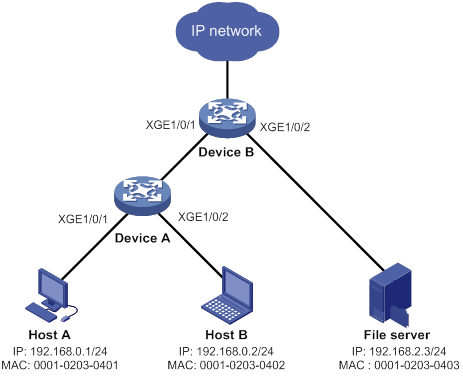
As shown in Figure 1, Host A, Host B, and the file server use static IPv4 addresses.
Enable static IPv4SG and configure static IPSG bindings on Device A and Device B to meet the following requirements:
· The interface Ten-GigabitEthernet 1/0/1 of Device A allows IP packets from Host A to pass.
· All interfaces of Device A allow IP packets from Host B to pass.
· The interface Ten-GigabitEthernet 1/0/1 of Device B allows only IP packets from Host A and Host B to pass.
· The interface Ten-GigabitEthernet 1/0/2 of Device B allows only IP packets from the file server to pass.
Analysis
To meet the network requirements, you must perform the following tasks:
· To allow IP packets from Host A to pass through Ten-GigabitEthernet 1/0/1 on Device A, configure a static IPSG binding for Host A on the interface.
· To allow IP packets from Host B to pass through all interfaces on Device A, configure a global static IPSG binding for Host B.
· To allow IP packets from both hosts to pass through Ten-GigabitEthernet 1/0/1 on Device B, configure static IPSG bindings for the hosts on the interface.
· To allow only IP packets from the file server to pass through Ten-GigabitEthernet 1/0/2 on Device B, configure a static IPSG binding for the file server on the interface.
Applicable hardware and software versions
The following matrix shows the hardware and software versions to which this configuration example is applicable:
|
Hardware |
Software version |
|
S6800 switch series S6860 switch series S6861 switch series |
Release 2702 |
Restrictions and guidelines
IPSG does not use the VLAN information (if specified) in static IPSG bindings to filter packets.
Procedures
Configuring Device A
# Create VLAN 10, and assign Ten-GigabitEthernet 1/0/1 through Ten-GigabitEthernet 1/0/2 to VLAN 10.
<DeviceA> system-view
[DeviceA] vlan 10
[DeviceA-vlan10] port ten-gigabitethernet 1/0/1 to ten-gigabitethernet 1/0/2
[DeviceA-vlan10] quit
# Create VLAN-interface 10, and assign an IP address to VLAN-interface 10.
[DeviceA] interface vlan-interface 10
[DeviceA-Vlan-interface10] ip address 192.168.0.10 255.255.255.0
[DeviceA-Vlan-interface10] quit
# Enable IPv4SG on Ten-GigabitEthernet 1/0/1 and GigabitEthernet 1/0/2.
[DeviceA] interface ten-gigabitethernet 1/0/2
[DeviceA-Ten-GigabitEthernet1/0/2] ip verify source ip-address mac-address
[DeviceA-Ten-GigabitEthernet1/0/2] quit
[DeviceA] interface ten-gigabitethernet 1/0/1
[DeviceA-Ten-GigabitEthernet1/0/1] ip verify source ip-address mac-address
# Configure a static IPSG binding for Host A on Ten-GigabitEthernet 1/0/1.
[DeviceA-Ten-GigabitEthernet1/0/1] ip source binding ip-address 192.168.0.1 mac-address 0001-0203-0401
[DeviceA-Ten-GigabitEthernet1/0/1] quit
# Configure a static IPSG binding for Host B.
[DeviceA] ip source binding ip-address 192.168.0.2 mac-address 0001-0203-0402
Configuring Device B
# Create VLAN 10, and assign Ten-GigabitEthernet 1/0/1 to VLAN 10.
<DeviceB> system-view
[DeviceB] vlan 10
[DeviceB-vlan10] port ten-gigabitethernet 1/0/1
[DeviceB-vlan10] quit
# Create VLAN-interface 10, and assign an IP address to VLAN-interface 10.
[DeviceB] interface vlan-interface 10
[DeviceB-Vlan-interface10] ip address 192.168.0.100 255.255.255.0
[DeviceB-Vlan-interface10] quit
# Create VLAN 20, and assign Ten-GigabitEthernet 1/0/2 to VLAN 20.
[DeviceB] vlan 20
[DeviceB-vlan20] port ten-gigabitethernet 1/0/2
[DeviceB-vlan20] quit
# Create VLAN-interface 20, and assign an IP address to VLAN-interface 20.
[DeviceB] interface vlan-interface 20
[DeviceB-Vlan-interface20] ip address 192.168.2.100 255.255.255.0
[DeviceB-Vlan-interface20] quit
# Enable IPv4SG on Ten-GigabitEthernet 1/0/1.
[DeviceB] interface ten-gigabitethernet 1/0/1
[DeviceB-Ten-GigabitEthernet1/0/1] ip verify source ip-address mac-address
# Configure static IPSG bindings for Host A and Host B on Ten-GigabitEthernet 1/0/1.
[DeviceB-Ten-GigabitEthernet1/0/1] ip source binding ip-address 192.168.0.1 mac-address 0001-0203-0401
[DeviceB-Ten-GigabitEthernet1/0/1] ip source binding ip-address 192.168.0.2 mac-address 0001-0203-0402
[DeviceB-Ten-GigabitEthernet1/0/1] quit
# Enable IPSG on Ten-GigabitEthernet 1/0/2.
[DeviceB] interface ten-gigabitethernet 1/0/2
[DeviceB-Ten-GigabitEthernet1/0/2] ip verify source ip-address mac-address
# Configure a static IPSG binding for the file server on Ten-GigabitEthernet 1/0/2.
[DeviceB-Ten-GigabitEthernet1/0/2] ip source binding ip-address 192.168.2.3 mac-address 0001-0203-0403
[DeviceB-Ten-GigabitEthernet1/0/2] quit
Verifying the configuration
# Verify that Host A can ping the IP addresses of Ten-GigabitEthernet 1/0/1 on both Device A and Device B. (Details not shown.)
# Verify that Host B can ping the IP addresses of all interfaces of Device A and Ten-GigabitEthernet 1/0/1 of Device B. (Details not shown.)
# Verify that the file server can ping the IP address of VLAN-interface 20 of Device B. (Details not shown.)
# Verify that Device A has static IPSG bindings for Host A and Host B.
[DeviceA] display ip source binding static
Total entries found: 2
IP Address MAC Address Interface VLAN Type
192.168.0.2 0001-0203-0402 N/A N/A Static
192.168.0.1 0001-0203-0401 XGE1/0/1 N/A Static
# Verify that Device B has static IPSG bindings for Host A, Host B, and the file server.
[DeviceB] display ip source binding static
Total entries found: 3
IP Address MAC Address Interface VLAN Type
192.168.0.1 0001-0203-0401 XGE1/0/1 N/A Static
192.168.0.2 0001-0203-0402 XGE1/0/1 N/A Static
192.168.2.3 0001-0203-0403 XGE1/0/2 N/A Static
# Verify that Host B can ping Device A when Host B is connected to Device A through Ten-GigabitEthernet 1/0/1. (Details not shown.)
# Verify that Host B cannot ping Device A when Host B is assigned an IP address different from 192.168.0.2. (Details not shown.)
# Verify that Host A cannot ping Device A when any of following conditions exist (details not shown):
· Host A is connected to Device A through Ten-GigabitEthernet 1/0/2 or Ten-GigabitEthernet 1/0/3.
· Host A is assigned an IP address different from 192.168.0.1.
Configuration files
· Device A:
#
ip source binding ip-address 192.168.0.2 mac-address 0001-0203-0402
#
vlan 10
#
interface Vlan-interface10
ip address 192.168.0.10 255.255.255.0
#
interface Ten-GigabitEthernet1/0/1
port link-mode bridge
port access vlan 10
ip verify source ip-address mac-address
ip source binding ip-address 192.168.0.1 mac-address 0001-0203-0401
#
interface Ten-GigabitEthernet1/0/2
port link-mode bridge
port access vlan 10
ip verify source ip-address mac-address
#
· Device B:
#
vlan 10
#
vlan 20
#
interface Vlan-interface10
ip address 192.168.0.100 255.255.255.0
#
interface Vlan-interface20
ip address 192.168.2.100 255.255.255.0
#
interface Ten-GigabitEthernet1/0/1
port link-mode bridge
port access vlan 10
ip verify source ip-address mac-address
ip source binding ip-address 192.168.0.1 mac-address 0001-0203-0401
ip source binding ip-address 192.168.0.2 mac-address 0001-0203-0402
#
interface Ten-GigabitEthernet1/0/2
port link-mode bridge
port access vlan 20
ip verify source ip-address mac-address
ip source binding ip-address 192.168.2.3 mac-address 0001-0203-0403
#
Example: Configuring dynamic IPv4SG based on DHCP snooping
Network configuration
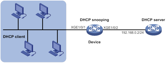
As shown in Figure 2, the DHCP clients obtain IP addresses from the DHCP server.
· Enable DHCP snooping on the device to make sure the DHCP clients obtain IP addresses from the authorized DHCP server.
· Enable dynamic IPv4SG on Ten-GigabitEthernet 1/0/1 to filter incoming packets by using the IPSG bindings that are generated based on DHCP snooping entries. Only packets from the DHCP clients are allowed to pass.
Analysis
To meet the network requirements, you must perform the following tasks:
· To enable the DHCP clients to obtain IP addresses from the DHCP server, configure Ten-GigabitEthernet 1/0/2 as the DHCP trusted port. By default, all ports are untrusted ports after DHCP snooping is enabled.
· To generate DHCP snooping entries for the DHCP clients, enable recording of client information in DHCP snooping entries on Ten-GigabitEthernet 1/0/1. By default, recording of DHCP snooping entries is disabled.
Applicable hardware and software versions
The following matrix shows the hardware and software versions to which this configuration example is applicable:
|
Hardware |
Software version |
|
S6800 switch series S6860 switch series S6861 switch series |
Release 2702 |
Procedures
This example uses an S6800, S6860, or S6861 switch as the DHCP server.
Configuring the DHCP server
# Create VLAN-interface 1, and assign an IP address to VLAN-interface 1.
<DHCPserver> system-view
[DHCPserver] interface vlan-interface 1
[DHCPserver-Vlan-interface1] ip address 192.168.0.2 24
# Enable the DHCP server on VLAN-interface 1.
[DHCPserver-Vlan-interface1] dhcp select server
[DHCPserver-Vlan-interface1] quit
# Enable DHCP.
[DHCPserver] dhcp enable
# Create DHCP address pool 1.
[DHCPserver] dhcp server ip-pool 1
# Specify the assignable subnet as 192.168.0.0/24 and the address lease duration as 7 days.
[DHCPserver-dhcp-pool-1] network 192.168.0.0 24
[DHCPserver-dhcp-pool-1] expired day 7
[DHCPserver-dhcp-pool-1] quit
Configuring the device
# Enable DHCP snooping.
<Device> system-view
[Device] dhcp snooping enable
# Configure Ten-GigabitEthernet 1/0/2 as a trusted port.
[Device] interface ten-gigabitethernet 1/0/2
[Device-Ten-GigabitEthernet1/0/2] dhcp snooping trust
[Device-Ten-GigabitEthernet1/0/2] quit
# Enable IPv4SG on Ten-GigabitEthernet 1/0/1 and verify the source IP address and MAC address for dynamic IPv4SG.
[Device] interface ten-gigabitethernet 1/0/1
[Device-Ten-GigabitEthernet1/0/1] ip verify source ip-address mac-address
# Enable recording of client information in DHCP snooping entries on Ten-GigabitEthernet 1/0/1.
[Device-Ten-GigabitEthernet1/0/1] dhcp snooping binding record
[Device-Ten-GigabitEthernet1/0/1] quit
Configuring the DHCP clients
# Configure the DHCP clients to use DHCP for IP address acquisition. (Details not shown.)
Verifying the configuration
# Verify that the device has generated dynamic IPSG bindings for the clients based on DHCP snooping entries.
[Device] display ip source binding dhcp-snooping
Total entries found: 4
IP Address MAC Address Interface VLAN Type
192.168.0.1 0001-0203-0401 XGE1/0/1 1 DHCP snooping
192.168.0.3 0001-0203-0403 XGE1/0/1 1 DHCP snooping
192.168.0.4 0001-0203-0404 XGE1/0/1 1 DHCP snooping
192.168.0.5 0001-0203-0405 XGE1/0/1 1 DHCP snooping
# Verify that the DHCP server can be pinged from the clients. (Details not shown.)
# Verify that the DHCP server cannot be pinged from the clients when the clients are assigned IP addresses manually. (Details not shown.)
Configuration files
#
vlan 1
#
dhcp snooping enable
#
interface Ten-GigabitEthernet1/0/1
port link-mode bridge
ip verify source ip-address mac-address
dhcp snooping binding record
#
interface Ten-GigabitEthernet1/0/2
port link-mode bridge
dhcp snooping trust
#
Example: Configuring dynamic IPv4SG based on DHCP relay agent
Network configuration
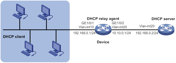
As shown in Figure 3, DHCP relay is enabled on the device. The DHCP clients obtain IP addresses from the DHCP server through the DHCP relay agent.
Enable dynamic IPv4SG on VLAN-interface 10 to filter incoming packets by using the dynamic IPSG bindings generated based on the DHCP relay entries.
Analysis
To generate DHCP relay entries for the DHCP clients, enable recording of relay entries on the delay agent. By default, the DHCP relay agent does not record client information in relay entries.
Applicable hardware and software versions
The following matrix shows the hardware and software versions to which this configuration example is applicable:
|
Hardware |
Software version |
|
S6800 switch series S6860 switch series S6861 switch series |
Release 2702 |
Procedures
This example uses an S6800, S6860, or S6861 switch as the DHCP server.
Configuring the DHCP server
# Create VLAN-interface 20, and assign an IP address to VLAN-interface 20.
<DHCPserver> system-view
[DHCPserver] interface vlan-interface 20
[DHCPserver-Vlan-interface20] ip address 10.10.0.2 24
# Enable the DHCP server on VLAN-interface 20.
[DHCPserver-Vlan-interface20] dhcp select server
[DHCPserver-Vlan-interface20] quit
# Enable DHCP.
[DHCPserver] dhcp enable
# Create DHCP address pool 1.
[DHCPserver] dhcp server ip-pool 1
# Specify the assignable subnet as 192.168.0.0/24 and the address lease duration as 7 days.
[DHCPserver-dhcp-pool-1] network 192.168.0.0 24
[DHCPserver-dhcp-pool-1] expired day 7
[DHCPserver-dhcp-pool-1] quit
# Configure a static route for the subnet where VLAN-interface 10 of the DHCP relay agent resides on the DHCP server.
[DHCPserver] ip route-static 192.168.0.0 24 10.10.0.1
Configuring the device
# Create VLAN 10, and assign Ten-GigabitEthernet 1/0/1 to VLAN 10.
<Device> system-view
[Device] vlan 10
[Device-vlan10] port ten-gigabitethernet 1/0/1
[Device-vlan10] quit
# Assign an IP address to VLAN-interface 10.
[Device] interface vlan-interface 10
[Device-Vlan-interface10] ip address 192.168.0.1 255.255.255.0
[Device-Vlan-interface10] quit
# Create VLAN 20, and assign Ten-GigabitEthernet 1/0/2 to VLAN 20.
[Device] vlan 20
[Device-vlan20] port ten-gigabitethernet 1/0/2
[Device-vlan20] quit
# Assign an IP address to VLAN-interface 20.
[Device] interface vlan-interface 20
[Device-Vlan-interface20] ip address 10.10.0.1 255.255.255.0
[Device-Vlan-interface20] quit
# Enable DHCP.
[Device] dhcp enable
# Enable recording of relay entries on the delay agent.
[Device] dhcp relay client-information record
# Enable the DHCP relay agent on VLAN-interface 10.
[Device] interface vlan-interface 10
[Device-Vlan-interface10] dhcp select relay
# Specify the IP address of the DHCP server on the relay agent.
[Device-Vlan-interface10] dhcp relay server-address 10.10.0.2
[Device-Vlan-interface10] quit
# Enable IPv4SG on VLAN-interface 10 and verify the source IP address and MAC address for dynamic IPSG.
[Device] interface vlan-interface 10
[Device-Vlan-interface10] ip verify source ip-address mac-address
[Device-Vlan-interface10] quit
Configuring the DHCP clients
# Configure the DHCP clients to use DHCP for IP address acquisition. (Details not shown.)
Verifying the configuration
# Verify that the device has generated dynamic IPSG bindings for the clients based on DHCP relay entries.
<Device> display ip source binding dhcp-relay
Total entries found: 4
IP Address MAC Address Interface VLAN Type
192.168.0.2 0001-0203-0402 Vlan10 10 DHCP relay
192.168.0.3 0001-0203-0403 Vlan10 10 DHCP relay
192.168.0.4 0001-0203-0404 Vlan10 10 DHCP relay
192.168.0.5 0001-0203-0405 Vlan10 10 DHCP relay
# Verify that the DHCP server can be pinged from the clients. (Details not shown.)
# Verify that the DHCP server cannot be pinged from the clients when the clients are assigned IP addresses manually. (Details not shown.)
Configuration files
#
dhcp enable
dhcp relay client-information record
#
vlan 10
#
vlan 20
#
interface Vlan-interface10
ip address 192.168.0.1 255.255.255.0
dhcp select relay
dhcp relay server-address 10.10.0.2
ip verify source ip-address mac-address
#
interface Vlan-interface20
ip address 10.10.0.1 255.255.255.0
#
interface Ten-GigabitEthernet1/0/1
port link-mode bridge
port access vlan 10
#
interface Ten-GigabitEthernet1/0/2
port link-mode bridge
port access vlan 20
#
Example: Configuring static IPv6SG and dynamic IPv6SG
Network configuration
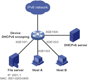
As shown in Figure 4, the file server uses static IPv6 address 2001::1. Host A and Host B obtain IP addresses from the DHCPv6 server.
Configure IPv6SG on the device to meet the following requirements:
· The interface Ten-GigabitEthernet 1/0/1 allows only packets from the file server to pass.
· The interface Ten-GigabitEthernet 1/0/2 allows only packets from Host A to pass.
· The interface Ten-GigabitEthernet 1/0/3 allows only packets from Host B to pass.
Analysis
To meet the network requirements, you must perform the following tasks:
· To enable Host A and Host B to obtain IP addresses from the DHCPv6 server, configure Ten-GigabitEthernet 1/0/4 as the DHCP trusted port. By default, all ports are untrusted ports after DHCPv6 snooping is enabled.
· To allow only incoming packets from the file server on Ten-GigabitEthernet 1/0/1, configure a static IPSG binding for the file server.
· To allow only packets from Host A to pass through Ten-GigabitEthernet 1/0/2 and only packets from Host B to pass through Ten-GigabitEthernet 1/0/3, perform the following tasks:
¡ Enable IPv6SG on Ten-GigabitEthernet 1/0/2 and Ten-GigabitEthernet 1/0/3.
¡ To generate DHCPv6 snooping entries for Host A and Host B, enable recording of client information in DHCPv6 snooping entries on Ten-GigabitEthernet 1/0/2 and Ten-GigabitEthernet 1/0/3. By default, recording of DHCP snooping entries is disabled.
Applicable hardware and software versions
The following matrix shows the hardware and software versions to which this configuration example is applicable:
|
Hardware |
Software version |
|
S6800 switch series S6860 switch series S6861 switch series |
Release 2702 |
Restrictions and guidelines
IPv6SG does not use the VLAN information (if specified) in static IPSG bindings to filter packets.
Procedures
# Configure the DHCPv6 server and the DHCPv6 clients (Host A and Host B). (Details not shown.)
# Enable IPv6SG on Ten-GigabitEthernet 1/0/1.
<Device> system-view
[Device] interface ten-gigabitethernet 1/0/1
[Device-Ten-GigabitEthernet1/0/1] ipv6 verify source ip-address mac-address
# Configure a static IPSG binding for the file server on Ten-GigabitEthernet 1/0/1.
[Device-Ten-GigabitEthernet1/0/1] ipv6 source binding ip-address 2001::1 mac-address 0001-0203-0405
[Device-Ten-GigabitEthernet1/0/1] quit
# Enable DHCPv6 snooping.
[Device] ipv6 dhcp snooping enable
# Configure Ten-GigabitEthernet 1/0/4 as a trusted port.
[Device] interface ten-gigabitethernet 1/0/4
[Device-Ten-GigabitEthernet1/0/4] ipv6 dhcp snooping trust
[Device-Ten-GigabitEthernet1/0/4] quit
# Enable IPv6SG on Ten-GigabitEthernet 1/0/2 and verify the source IPv6 address and MAC address for dynamic IPv6SG.
[Device] interface ten-gigabitethernet 1/0/2
[Device-Ten-GigabitEthernet1/0/2] ipv6 verify source ip-address mac-address
# Enable recording of client information in DHCPv6 snooping entries on Ten-GigabitEthernet 1/0/2.
[Device-Ten-GigabitEthernet1/0/2] ipv6 dhcp snooping binding record
[Device-Ten-GigabitEthernet1/0/2] quit
# Enable IPv6SG on Ten-GigabitEthernet 1/0/3 and verify the source IPv6 address and MAC address for dynamic IPv6SG.
[Device] interface ten-gigabitethernet 1/0/3
[Device-Ten-GigabitEthernet1/0/3] ipv6 verify source ip-address mac-address
# Enable recording of client information in DHCPv6 snooping entries on Ten-GigabitEthernet 1/0/3.
[Device-Ten-GigabitEthernet1/0/3] ipv6 dhcp snooping binding record
[Device-Ten-GigabitEthernet1/0/3] quit
Verifying the configuration
# Verify that the file server can ping the DHCPv6 server. (Details not shown.)
# Verify that the device has a static IPSG binding for the file server.
[Device] display ipv6 source binding static
Total entries found: 1
IPv6 Address MAC Address Interface VLAN Type
2001::1 0001-0203-0405 XGE1/0/1 N/A Static
# Verify that the device has generated dynamic IPSG bindings for Host A and Host B based on DHCP snooping entries.
[Device] display ipv6 source binding dhcpv6-snooping
Total entries found: 2
IPv6 Address MAC Address Interface VLAN Type
2001::2 0001-0203-0406 XGE1/0/2 1 DHCPv6 snooping
2001::3 0001-0203-0407 XGE1/0/3 1 DHCPv6 snooping
# Verify that Host A and Host B can ping the DHCPv6 server. (Details not shown.)
# Verify that Host A and Host B cannot ping the DHCPv6 server when they are assigned IPv6 addresses manually. (Details not shown.)
Configuration files
#
ipv6 dhcp snooping enable
#
interface Ten-GigabitEthernet1/0/1
port link-mode bridge
ipv6 verify source ip-address mac-address
ipv6 source binding ip-address 2001::1 mac-address 0001-0203-0405
#
interface Ten-GigabitEthernet1/0/2
port link-mode bridge
ipv6 verify source ip-address mac-address
ipv6 dhcp snooping binding record
#
interface Ten-GigabitEthernet1/0/3
port link-mode bridge
ipv6 verify source ip-address mac-address
ipv6 dhcp snooping binding record
#
interface Ten-GigabitEthernet1/0/4
port link-mode bridge
ipv6 dhcp snooping trust
#
Related documentation
· H3C S6800[S6860][S6861] (R27xx) & S6820 (R630x) Switch Series Security Configuration Guide
· H3C S6800[S6860][S6861] (R27xx) & S6820 (R630x) Switch Series Security Command Reference