- Table of Contents
-
- 06-Layer 3 - IP Routing Configuration Guide
- 00-Preface
- 01-IP Routing Basics
- 02-Static Routing Configuration
- 03-RIP Configuration
- 04-OSPF Configuration
- 05-IS-IS Configuration
- 06-BGP Configuration
- 07-Policy-Based Routing Configuration
- 08-IPv6 Static Routing Configuration
- 09-RIPng Configuration
- 10-OSPFv3 Configuration
- 11-IPv6 IS-IS Configuration
- 12-IPv6 BGP Configuration
- 13-IPv6 Policy-Based Routing Configuration
- 14-Routing Policy Configuration
- 15-QoS Policy Routing Configuration
- Related Documents
-
| Title | Size | Download |
|---|---|---|
| 14-Routing Policy Configuration | 198.73 KB |
Contents
Introduction to routing policy
Defining an extended community list
Displaying and maintaining the routing policy
Routing policy configuration examples
Applying a routing policy to IPv4 route redistribution
Applying a routing policy to IPv6 route redistribution
Applying a routing policy to filter received BGP routes
Troubleshooting routing policy configuration
IPv4 routing information filtering failure
IPv6 routing information filtering failure
Routing policies are used to receive, advertise and redistribute only specific routes and modify the attributes of some routes.
|
|
NOTE: Routing policy in this chapter involves both IPv4 routing policy and IPv6 routing policy. |
Introduction to routing policy
A routing policy is used to filter routes when they are received, advertised, or redistributed and modify the attributes of some routes.
Routing policy application
A routing policy has the following applications:
· Filters advertised routes.
· Filters received routes.
· Filters redistributed routes.
· Modifies or sets the attributes of some routes.
Routing policy implementation
To configure a routing policy, you must do the following:
1. Define some filters based on the attributes of routing information, such as destination address, and the advertising router’s address.
2. Apply the filters to the routing policy.
You can use multiple filters to define match criteria. For detailed information, see “Filters.”
Filters
You can use the following types of filters: ACL, IP prefix list, AS path ACL, community list, extended community list, and routing policy.
ACL
ACL involves IPv4 ACL and IPv6 ACL. An ACL is configured to match the destinations or next hops of routing information.
For more information about ACL, see ACL and QoS Configuration Guide.
IP prefix list
IP prefix list involves IPv4 prefix list and IPv6 prefix list.
An IP prefix list is configured to match the destination address of routing information. You can use the gateway option to allow only routing information from certain routers to be received. For gateway option information, see the chapters “Configuring RIP” and “Configuring OSPF.”
An IP prefix list, identified by name, can comprise multiple items. Each item, identified by an index number, can specify a prefix range to match. An item with a smaller index number is matched first. If one item is matched, the IP prefix list is passed, and the packet will not go to the next item.
AS-PATH list
An AS-PATH list, configured based on the BGP AS PATH attribute, can only be used to match BGP routing information.
For more information about AS-PATH list, see the chapter “Configuring BGP.”
Community list
A community list, configured based on the BGP community attribute, can only be used to match BGP routing information.
For more information about community list, see the chapter “Configuring BGP.”
Extended community list
An extended community list, configured based on the BGP extended community attribute (Route-Target for VPN, and Source of Origin), can only be used to match BGP routing information.
For more information about extended community list, see MPLS Configuration Guide.
Routing policy
A routing policy is used to match routing information and modify the attributes of permitted routes. It can reference the filters to define its own match criteria.
A routing policy can comprise multiple nodes, which are in logic OR relationship. Each routing policy node is a match unit, and a node with a smaller number is matched first. Once a node is matched, the routing policy is passed and the packet will not go to the next node.
A routing policy node comprises a set of if-match, apply, and continue clauses.
· The if-match clauses define the match criteria. The matching objects are some attributes of routing information. The if-match clauses of a routing policy node is in a logical AND relationship. A packet must match all the if-match clauses of the node to pass it.
· The apply clauses of the node specify the actions to be taken on the permitted packets, such as modifying a route attribute.
· The continue clause specifies the next routing policy node to be matched. With this clause configured, when a route matches the current routing policy node, it continues to match against the specified next node in the same routing policy. The continue clause combines the if-match and apply clauses of the two nodes to improve flexibility of the routing policy.
When you configure if-match, apply, and continue clauses, follow these guidelines:
· If you want to implement route filtering only, you do not need to configure apply clauses.
· If you do not configure any if-match clauses for a permit-mode node, the node permits all routes to pass.
· Configure a permit-mode node containing no if-match or apply clauses behind multiple deny-mode nodes to allow unmatched routes to pass.
Defining filters
Configuration prerequisites
Before you configure this task, you must determine IP-prefix list name, matching address range, and extcommunity list sequence number.
Defining an IP-prefix list
Defining an IPv4 prefix list
Identified by name, an IPv4 prefix list can comprise multiple items. Each item specifies a prefix range to match and is identified by an index number.
An item with a smaller index number is matched first. If one item is matched, the IP prefix list is passed, and the routing information will not go to the next item.
To define an IPv4 prefix list:
|
Step |
Command |
Remarks |
|
1. Enter system view. |
system-view |
N/A |
|
2. Define an IPv4 prefix list. |
ip ip-prefix ip-prefix-name [ index index-number ] { deny | permit } ip-address mask-length [ greater-equal min-mask-length ] [ less-equal max-mask-length ] |
Not defined by default |
|
|
NOTE: If all the items are set to the deny mode, no routes can pass the IPv4 prefix list. You must define the permit 0.0.0.0 0 less-equal 32 item following multiple deny items to allow other IPv4 routing information to pass. |
For example, the following configuration filters routes 10.1.0.0/16, 10.2.0.0/16 and 10.3.0.0/16, but allows other routes to pass.
<Sysname> system-view
[Sysname] ip ip-prefix abc index 10 deny 10.1.0.0 16
[Sysname] ip ip-prefix abc index 20 deny 10.2.0.0 16
[Sysname] ip ip-prefix abc index 30 deny 10.3.0.0 16
[Sysname] ip ip-prefix abc index 40 permit 0.0.0.0 0 less-equal 32
Defining an IPv6 prefix list
Identified by name, each IPv6 prefix list can comprise multiple items. Each item specifies a prefix range to match and is identified by an index number.
An item with a smaller index number is matched first. If one item is matched, the IPv6 prefix list is passed, and the routing information will not go to the next item.
To define an IPv6 prefix list:
|
Step |
Command |
Remarks |
|
1. Enter system view. |
system-view |
N/A |
|
2. Define an IPv6 prefix list. |
ip ipv6-prefix ipv6-prefix-name [ index index-number ] { deny | permit } ipv6-address prefix-length [ greater-equal min-prefix-length ] [ less-equal max-prefix-length ] |
Not defined by default |
|
|
NOTE: If all items are set to the deny mode, no routes can pass the IPv6 prefix list. You must define the permit :: 0 less-equal 128 item following multiple deny items to allow other IPv6 routing information to pass. |
For example, the following configuration filters routes 2000:1::/48, 2000:2::/48 and 2000:3::/48, but allows other routes to pass.
<Sysname> system-view
[Sysname] ip ipv6-prefix abc index 10 deny 2000:1:: 48
[Sysname] ip ipv6-prefix abc index 20 deny 2000:2:: 48
[Sysname] ip ipv6-prefix abc index 30 deny 2000:3:: 16
[Sysname] ip ipv6-prefix abc index 40 permit :: 0 less-equal 128
Defining an AS path list
You can define multiple items for an AS path list that is identified by number. The relation between items is logical OR. If a route matches one of these items, it passes the AS path list.
To define an AS path list:
|
Step |
Command |
Remarks |
|
1. Enter system view. |
system-view |
N/A |
|
2. Define an AS path ACL. |
ip as-path as-path-number { deny | permit } regular-expression |
Not defined by default |
Defining a community list
You can define multiple items for a community list that is identified by number. During matching, the relation between items is logic OR. If routing information matches one of these items, it passes the community list.
To define a community list:
|
Step |
Command |
Remarks |
|
1. Enter system view. |
system-view |
N/A |
|
2. Define a community list. |
·
Define a basic community list: |
Use either approach. Not defined by default. |
|
·
Define an advanced community list: |
Defining an extended community list
You can define multiple items for an extended community list that is identified by number. During matching, the relation between items is logic OR. If routing information matches one of these items, it passes the extended community list.
To define an extended community list:
|
Step |
Command |
Remarks |
|
1. Enter system view. |
system-view |
N/A |
|
2. Define an extended community list. |
ip extcommunity-list ext-comm-list-number { deny | permit } { rt route-target }&<1-16> |
Not defined by default |
Configuring a routing policy
A routing policy is used to filter routing information, and modify attributes of matching routing information. The match criteria of a routing policy can be configured by referencing the appropriate filters.
A routing policy can comprise multiple nodes, and each routing policy node contains:
· if-match clauses—Define the match criteria that routing information must satisfy. The matching objects are some attributes of routing information.
· apply clauses—Specify the actions to be taken on routing information that has satisfied the match criteria, such as route attribute modification.
· continue clauses—Specify the next routing policy node to be matched. With this clause configured, when a route matches the current routing policy node, it continues to match against the specified next node in the same routing policy.
Configuration prerequisites
Before you configure this task, you must configure filters and routing protocols, and decide on name of the routing policy and node numbers, match criteria, and attributes to be modified.
Creating a routing policy
To create a routing policy:
|
Step |
Command |
|
1. Enter system view. |
system-view |
|
2. Create a routing policy, specify a node for it and enter routing policy view. |
route-policy route-policy-name { deny | permit } node node-number |
|
|
NOTE: · If a routing policy node has the permit keyword specified, routing information matching all the if-match clauses of the node will be handled using the apply clauses of this node, without needing to match against the next node. If routing information does not match the node, it will go to the next node for a match. · If a routing policy node has the deny keyword specified, the apply clauses of the node will not be executed. When routing information matches all the if-match clauses of the node, it cannot pass the node, or go to the next node. If route information cannot match all the if-match clauses of the node, it will go to the next node for a match. · When a routing policy has more than one node, at least one node should be configured with the permit keyword. If the routing policy is used to filter routing information, routing information that does not meet any node cannot pass the routing policy. If all nodes of the routing policy are set with the deny keyword, no routing information can pass it. |
Defining if-match clauses
To define if-match clauses for a routing policy:
|
Step |
Command |
Remarks |
|
1. Enter system view. |
system-view |
N/A |
|
2. Enter routing policy view. |
route-policy route-policy-name { deny | permit } node node-number |
N/A |
|
3. Define match criteria for IPv4 routes. |
·
Match IPv4 routing information specified in
the ACL: ·
Match IPv4 routing information specified in
the IP prefix list: ·
Match IPv4 routing information whose next hop
or source is specified in the ACL or IP prefix list: |
Optional Not configured by default |
|
4. Match IPv6 routing information whose next hop or source is specified in the ACL or IP prefix list. |
if-match ipv6 { address | next-hop | route-source } { acl acl-number | prefix-list ipv6-prefix-name } |
Optional Not configured by default |
|
5. Match BGP routing information whose AS path attribute is specified in the AS path list (s). |
if-match as-path AS-PATH-number&<1-16> |
Optional Not configured by default |
|
6. Match BGP routing information whose community attribute is specified in the community list(s). |
if-match community { { basic-community-list-number | comm-list-name } [ whole-match ] | adv-community-list-number }&<1-16> |
Optional Not configured by default |
|
7. Match routes having the specified cost. |
if-match cost value |
Optional Not configured by default |
|
8. Match BGP routing information whose extended community attribute is specified in the extended community list(s). |
if-match extcommunity ext-comm-list-number&<1-16> |
Optional Not configured by default |
|
9. Match routing information having specified outbound interface(s). |
if-match interface { interface-type interface-number }&<1-16> |
Optional Not configured by default |
|
10. Match routing information having MPLS labels. |
if-match mpls-label |
Optional Not configured by default |
|
11. Match routing information having the specified route type. |
if-match route-type { external-type1 | external-type1or2 | external-type2 | internal | is-is-level-1 | is-is-level-2 | nssa-external-type1 | nssa-external-type1or2 | nssa-external-type2 } * |
Optional Not configured by default |
|
12. Match RIP, OSPF, and IS-IS routing information having the specified tag value. |
if-match tag value |
Optional Not configured by default |
|
|
NOTE: · The if-match clauses of a routing policy node are in logic AND relationship. Routing information has to satisfy all its if-match clauses before being executed with its apply clauses. If an if-match command exceeds the maximum length, multiple idendical if-match clauses are generated. These clauses are in logical OR relationship. Routing information only needs to match one of them. · You can specify any number of if-match clauses for a routing policy node. If no if-match clause is specified, and the routing policy node is in permit mode, all routing information can pass the node. If it is in deny mode, no routing information can pass it. · If the ACL referenced by an if-match clause does not exist, the clause is always satisfied; if no rules of the referenced ACL are matched or the matching rule is inactive, the clause is not satisfied. · An ACL specified in an if-match clause should be a non-VPN ACL. · The if-match commands for matching IPv4 destination, next hop and source address are different from those for matching IPv6 ones. · BGP does not support criteria for matching against outbound interfaces of routing information. |
Defining apply clauses
To define apply clauses for a routing policy:
|
Step |
Command |
Remarks |
|
1. Enter system view. |
system-view |
N/A |
|
2. Enter routing policy view. |
route-policy route-policy-name { deny | permit } node node-number |
Not created by default. |
|
3. Set the AS-PATH attribute for BGP routing information. |
Optional. Not set by default. |
|
|
4. Delete the community attribute of BGP routing information using the community list. |
apply comm-list { comm-list-number | comm-list-name } delete |
Optional. Not configured by default. |
|
5. Set the community attribute for BGP routing information. |
apply community { none | additive | { community-number&<1-16> | aa:nn&<1-16> | internet | no-advertise | no-export | no-export-subconfed } * [ additive ] } |
Optional. Not set by default. |
|
6. Set a cost for routing information. |
apply cost [ + | - ] value |
Optional. Not set by default. |
|
7. Set a cost type for routing information. |
apply cost-type [ external | internal | type-1 | type-2 ] |
Optional. Not set by default. |
|
8. Set the extended community attribute for BGP routing. |
apply extcommunity { rt { as-number:nn | ip-address:nn } }&<1-16> [ additive ] |
Optional Not set by default. |
|
9. Set the next hop. |
·
Set the next hop for IPv4 routes: ·
Set the next hop for IPv6 routes: |
Optional. Not set by default. The setting does not apply to redistributed routing information. |
|
10. Inject routing information to a specified ISIS level. |
apply isis { level-1 | level-1-2 | level-2 } |
Optional. Not configured by default. |
|
11. Set the local preference for BGP routing information. |
apply local-preference preference |
Optional. Not set by default. |
|
12. Set MPLS label. |
apply mpls-label |
Optional. Not set by default. |
|
13. Set the origin attribute for BGP routing information. |
apply origin { egp as-number | igp | incomplete } |
Optional Not set by default. |
|
14. Set the preference for the routing protocol. |
apply preference preference |
Optional. Not set by default. |
|
15. Set a preferred value for BGP routing information. |
apply preferred-value preferred-value |
Optional. Not set by default. |
|
16. Set a tag value for RIP, OSPF, IS-IS, RIPng, or IPv6 IS-IS routing information. |
apply tag value |
Optional. Not set by default. |
|
17. Set a FRR backup outbound interface and a backup next hop. |
apply fast-reroute backup-interface interface-type interface-number [ backup-nexthop ip-address ] |
Optional. Not configured by default. |
|
|
NOTE: · The difference between IPv4 and IPv6 apply clauses is the command for setting the next hop for routing information. · The apply ip-address next-hop and apply ipv6 next-hop commands do not apply to redistributed IPv4 and IPv6 routes respectively. · The apply tag command is not supported at present. |
Defining a continue clause
To define a continue clause for a routing policy:
|
Step |
Command |
Remarks |
|
1. Enter system view. |
system-view |
N/A |
|
2. Create a routing policy and enter routing policy view. |
route-policy route-policy-name { deny | permit } node node-number |
Not created by default. |
|
3. Specify the next routing policy node to be matched. |
Optional. Not configured by default. The node number specified must be larger than the current node number. |
|
|
NOTE: · If you configure the same type of apply clauses that set different values (including the apply community and apply extcommunity clauses with the additive keyword) on nodes that are combined by the continue clause, the apply clause configured on the last matching node takes effect. · If you configure the apply community clause for multiple nodes that are combined by the continue clause, the apply comm-list delete clause configured on the current node cannot delete the community attributes of preceding nodes. |
Displaying and maintaining the routing policy
|
Task |
Command |
Remarks |
|
Display BGP AS-PATH list information. |
display ip as-path [ as-path-number ] [ | { begin | exclude | include } regular-expression ] |
Available in any view |
|
Display BGP community list information. |
display ip community-list [ basic-community-list-number | adv-community-list-number | comm-list-name ] [ | { begin | exclude | include } regular-expression ] |
Available in any view |
|
Display BGP extended community list information. |
display ip extcommunity-list [ ext-comm-list-number ] [ | { begin | exclude | include } regular-expression ] |
Available in any view |
|
Display IPv4 prefix list statistics. |
display ip ip-prefix [ ip-prefix-name ] [ | { begin | exclude | include } regular-expression ] |
Available in any view |
|
Display IPv6 prefix list statistics. |
display ip ipv6-prefix [ ipv6-prefix-name ] [ | { begin | exclude | include } regular-expression ] |
Available in any view |
|
Display routing policy information. |
display route-policy [ route-policy-name ] [ | { begin | exclude | include } regular-expression ] |
Available in any view |
|
Clear IPv4 prefix list statistics. |
reset ip ip-prefix [ ip-prefix-name ] |
Available in user view |
|
Clear IPv6 prefix list statistics. |
reset ip ipv6-prefix [ ipv6-prefix-name ] |
Available in user view |
Routing policy configuration examples
Applying a routing policy to IPv4 route redistribution
Network requirements
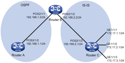
In Figure 1, Router B exchanges routing information with Router A using OSPF, and with Router C using IS-IS.
Configure Router B to redistribute IS-IS routes into the OSPF routing domain, and use a routing policy to set the cost of route 172.17.1.0/24 to 100, and the tag of route 172.17.2.0/24 to 20.
Configuration procedure
1. Configure IP addresses for interfaces. (Details not shown)
2. Configure IS-IS:
# Configure Router C.
<RouterC> system-view
[RouterC] isis
[RouterC-isis-1] is-level level-2
[RouterC-isis-1] network-entity 10.0000.0000.0001.00
[RouterC-isis-1] quit
[RouterC] interface POS 2/1/2
[RouterC-POS2/1/2] isis enable
[RouterC-POS2/1/2] quit
[RouterC] interface GigabitEthernet1/1/1
[RouterC-GigabitEthernet1/1/1] isis enable
[RouterC-GigabitEthernet1/1/1] quit
[RouterC] interface GigabitEthernet1/1/2
[RouterC-GigabitEthernet1/1/2] isis enable
[RouterC-GigabitEthernet1/1/2] quit
[RouterC] interface GigabitEthernet1/1/3
[RouterC-GigabitEthernet1/1/3] isis enable
[RouterC-GigabitEthernet1/1/3] quit
# Configure Router B.
<RouterB> system-view
[RouterB] isis
[RouterB-isis-1] is-level level-2
[RouterB-isis-1] network-entity 10.0000.0000.0002.00
[RouterB-isis-1] quit
[RouterB] interface POS 2/1/2
[RouterB-POS2/1/2] clock master
[RouterB-POS2/1/2] isis enable
[RouterB-POS2/1/2] quit
3. Configure OSPF and route redistribution:
# Configure OSPF on Router A.
<RouterA> system-view
[RouterA] ospf
[RouterA-ospf-1] area 0
[RouterA-ospf-1-area-0.0.0.0] network 192.168.1.0 0.0.0.255
[RouterA-ospf-1-area-0.0.0.0] quit
[RouterA-ospf-1] quit
# On Router B, configure OSPF and enable route redistribution from IS-IS.
[RouterB] ospf
[RouterB-ospf-1] area 0
[RouterB-ospf-1-area-0.0.0.0] network 192.168.1.0 0.0.0.255
[RouterB-ospf-1-area-0.0.0.0] quit
[RouterB-ospf-1] import-route isis 1
[RouterB-ospf-1] quit
# Display the OSPF routing table on Router A. The redistributed routes are available.
[RouterA] display ospf routing
OSPF Process 1 with Router ID 192.168.1.1
Routing Tables
Routing for Network
Destination Cost Type NextHop AdvRouter Area
192.168.1.0/24 1 Transit 192.168.1.1 192.168.1.1 0.0.0.0
Routing for ASEs
Destination Cost Type Tag NextHop AdvRouter
172.17.1.0/24 1 Type2 1 192.168.1.2 192.168.2.2
172.17.2.0/24 1 Type2 1 192.168.1.2 192.168.2.2
172.17.3.0/24 1 Type2 1 192.168.1.2 192.168.2.2
192.168.2.0/24 1 Type2 1 192.168.1.2 192.168.2.2
Total Nets: 5
Intra Area: 1 Inter Area: 0 ASE: 4 NSSA: 0
4. Configure filtering lists on Router B:
# Configure ACL 2002 to allow route 172.17.2.0/24 to pass.
[RouterB] acl number 2002
[RouterB-acl-basic-2002] rule permit source 172.17.2.0 0.0.0.255
[RouterB-acl-basic-2002] quit
# Configure IP prefix list prefix-a to allow route 172.17.1.0/24 to pass.
[RouterB] ip ip-prefix prefix-a index 10 permit 172.17.1.0 24
5. Configure a routing policy on Router B:
[RouterB] route-policy isis2ospf permit node 10
[RouterB-route-policy] if-match ip-prefix prefix-a
[RouterB-route-policy] apply cost 100
[RouterB-route-policy] quit
[RouterB] route-policy isis2ospf permit node 20
[RouterB-route-policy] if-match acl 2002
[RouterB-route-policy] apply tag 20
[RouterB-route-policy] quit
[RouterB] route-policy isis2ospf permit node 30
[RouterB-route-policy] quit
6. Apply the routing policy to route redistribution on Router B:
# On Router B, enable route redistribution from IS-IS and apply the routing policy.
[RouterB] ospf
[RouterB-ospf-1] import-route isis 1 route-policy isis2ospf
[RouterB-ospf-1] quit
# Display OSPF routing table information on Router A. The cost of route 172.17.1.0/24 is 100, and the tag of route 172.17.2.0/24 is 20.
[RouterA] display ospf routing
OSPF Process 1 with Router ID 192.168.1.1
Routing Tables
Routing for Network
Destination Cost Type NextHop AdvRouter Area
192.168.1.0/24 1 Transit 192.168.1.1 192.168.1.1 0.0.0.0
Routing for ASEs
Destination Cost Type Tag NextHop AdvRouter
172.17.1.0/24 100 Type2 1 192.168.1.2 192.168.2.2
172.17.2.0/24 1 Type2 20 192.168.1.2 192.168.2.2
172.17.3.0/24 1 Type2 1 192.168.1.2 192.168.2.2
192.168.2.0/24 1 Type2 1 192.168.1.2 192.168.2.2
Total Nets: 5
Intra Area: 1 Inter Area: 0 ASE: 4 NSSA: 0
Applying a routing policy to IPv6 route redistribution
Network requirements
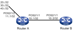
· In Figure 2, both Router A and Router B run RIPng.
· Enable RIPng and configure three static routes on Router A
· On Router A, enable static route redistribution into RIPng and apply a routing policy to permit routes 20::/32 and 40::/32 and deny route 30::/32.
· Display RIPng routing table information on Router B to verify the configuration.
Configuraion procedure
1. Configure Router A:
# Configure IPv6 addresses for interfaces POS2/1/1 and POS2/1/1, and enable PPP on them.
<RouterA> system-view
[RouterA] ipv6
[RouterA] interface POS 2/1/1
[RouterA-POS2/1/1] clock master
[RouterA-POS2/1/1] ipv6 address 10::1 32
[RouterA-POS2/1/1] link-protocol ppp
[RouterA-POS2/1/1] quit
[RouterA] interface POS 2/1/2
[RouterA-POS2/1/2] ipv6 address 11::1 32
[RouterA-POS2/1/2] link-protocol ppp
[RouterA-POS2/1/2] quit
# Enable RIPng on POS2/1/1.
[RouterA] interface POS 2/1/1
[RouterA-POS2/1/1] ripng 1 enable
[RouterA-POS2/1/1] quit
# Configure three static routes on Router A.
[RouterA] ipv6 route-static 20:: 32 POS 2/1/2
[RouterA] ipv6 route-static 30:: 32 POS 2/1/2
[RouterA] ipv6 route-static 40:: 32 POS 2/1/2
# Configure a routing policy.
[RouterA] ip ipv6-prefix a index 10 permit 30:: 32
[RouterA] route-policy static2ripng deny node 0
[RouterA-route-policy] if-match ipv6 address prefix-list a
[RouterA-route-policy] quit
[RouterA] route-policy static2ripng permit node 10
[RouterA-route-policy] quit
# Enable RIPng and apply routing policy static3ripng to filter redistributed static routes on Router A.
[RouterA] ripng
[RouterA-ripng-1] import-route static route-policy static2ripng
2. Configure Router B:
# Configure the IPv6 address of POS2/1/1, and enable PPP on it.
<RouterB> system-view
[RouterB] ipv6
[RouterB] interface POS 2/1/1
[RouterB-POS2/1/1] ipv6 address 10::2 32
[RouterB-POS2/1/1] link-protocol ppp
# Enable RIPng on the interface.
[RouterB-POS2/1/1] ripng 1 enable
[RouterB-POS2/1/1] quit
# Enable RIPng.
[RouterB] ripng
# Display RIPng routing table information.
[RouterB-ripng-1] display ripng 1 route
Route Flags: A - Aging, S - Suppressed, G - Garbage-collect
----------------------------------------------------------------
Peer FE80::7D58:0:CA03:1 on POS2/1/1
Dest 10::/32,
via FE80::7D58:0:CA03:1, cost 1, tag 0, A, 18 Sec
Dest 20::/32,
via FE80::7D58:0:CA03:1, cost 1, tag 0, A, 8 Sec
Dest 40::/32,
via FE80::7D58:0:CA03:1, cost 1, tag 0, A, 3 Sec
Applying a routing policy to filter received BGP routes
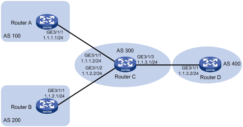
Network requirements
· In Figure 3, all the routers run BGP. Router C establishes EBGP connections with other routers.
· Configure a routing policy on Router D to reject routes from AS 200.
Configuration procedure
1. Configure IP addresses for interfaces. (Details not shown)
2. Configure BGP:
# Configure Router A.
<RouterA> system-view
[RouterA] bgp 100
[RouterA-bgp] router-id 1.1.1.1
[RouterA-bgp] peer 1.1.1.2 as-number 300
# Configure Router B.
<RouterB> system-view
[RouterB] bgp 200
[RouterB-bgp] router-id 2.2.2.2
[RouterB-bgp] peer 1.1.2.2 as-number 300
# Configure Router C.
<RouterC> system-view
[RouterC] bgp 300
[RouterC-bgp] router-id 3.3.3.3
[RouterC-bgp] peer 1.1.1.1 as-number 100
[RouterC-bgp] peer 1.1.2.1 as-number 200
[RouterC-bgp] peer 1.1.3.2 as-number 400
# Configure Router D.
<RouterD> system-view
[RouterD] bgp 400
[RouterD-bgp] router-id 4.4.4.4
[RouterD-bgp] peer 1.1.3.1 as-number 300
[RouterD-bgp] quit
# Inject routes 4.4.4.4/24, 5.5.5.5/24, and 6.6.6.6/24 on Router A.
[RouterA-bgp] network 4.4.4.4 24
[RouterA-bgp] network 5.5.5.5 24
[RouterA-bgp] network 6.6.6.6 24
# Inject routes 7.7.7.7/24, 8.8.8.8/24, and 9.9.9.9/24 on Router B.
[RouterB-bgp] network 7.7.7.7 24
[RouterB-bgp] network 8.8.8.8 24
[RouterB-bgp] network 9.9.9.9 24
# Display the BGP routing table information of Router D.
[RouterD-bgp] display bgp routing-table
Total Number of Routes: 6
BGP Local router ID is 4.4.4.4
Status codes: * - valid, > - best, d - damped,
h - history, i - internal, s - suppressed, S - Stale
Origin : i - IGP, e - EGP, ? - incomplete
Network NextHop MED LocPrf PrefVal Path/Ogn
*> 4.4.4.0/24 1.1.3.1 0 300 100i
*> 5.5.5.0/24 1.1.3.1 0 300 100i
*> 6.6.6.0/24 1.1.3.1 0 300 100i
*> 7.7.7.0/24 1.1.3.1 0 300 200i
*> 8.8.8.0/24 1.1.3.1 0 300 200i
*> 9.9.9.0/24 1.1.3.1 0 300 200i
The routing table information above shows that Router D has learned routes 4.4.4.0/24, 5.5.5.0/24, and 6.6.6.0/24 from AS 100 and 7.7.7.0/24, 8.8.8.0/24, and 9.9.9.0/24 from AS 200.
3. Configure Router D to reject the routes from AS 200:
# Configure AS-PATH list 1.
[RouterD] ip as-path 1 permit .*200.*
# Create routing policy rt1 with node 1, and specify the match mode as deny to deny routes from AS 200.
[RouterD] route-policy rt1 deny node 1
[RouterD-route-policy] if-match as-path 1
[RouterD-route-policy] quit
# On Router D, specify routing policy rt1 to filter routes received from peer 1.1.3.1.
[RouterD] bgp 400
[RouterD] peer 1.1.3.1 route-policy rt1 import
# Create routing policy rt1 with node 10, and specify the match mode as permit to permit routes from other ASs.
[RouterD] route-policy rt1 permit node 10
[RouterD-route-policy] quit
# Display the BGP routing table information of Router D.
[RouterD] display bgp routing-table
Total Number of Routes: 3
BGP Local router ID is 4.4.4.4
Status codes: * - valid, > - best, d - damped,
h - history, i - internal, s - suppressed, S - Stale
Origin : i - IGP, e - EGP, ? - incomplete
Network NextHop MED LocPrf PrefVal Path/Ogn
*> 4.4.4.0/24 1.1.3.1 0 300 100i
*> 5.5.5.0/24 1.1.3.1 0 300 100i
*> 6.6.6.0/24 1.1.3.1 0 300 100i
The output shows that Router D has learned only routes 4.4.4.0/24, 5.5.5.0/24, and 6.6.6.0/24 from AS 100.
Troubleshooting routing policy configuration
IPv4 routing information filtering failure
Symptom
The routing protocol is running properly, but filtering routing information failed.
Analysis
At least one item of the IP prefix list should be configured as permit mode, and at least one node in the routing policy should be configured as permit mode.
Solution
1. Use the display ip ip-prefix command to display IP prefix list information.
2. Use the display route-policy command to display routing policy information.
IPv6 routing information filtering failure
Symptom
The routing protocol is running properly, but filtering routing information failed.
Analysis
At least one item of the IPv6 prefix list should be configured as permit mode, and at least one node of the routing policy should be configured as permit mode.
Solution
1. Use the display ip ipv6-prefix command to display IP prefix list information.
2. Use the display route-policy command to display routing policy information.