- Table of Contents
-
- 06-Layer 3 - IP Routing Configuration Guide
- 00-Preface
- 01-IP Routing Basics
- 02-Static Routing Configuration
- 03-RIP Configuration
- 04-OSPF Configuration
- 05-IS-IS Configuration
- 06-BGP Configuration
- 07-Policy-Based Routing Configuration
- 08-IPv6 Static Routing Configuration
- 09-RIPng Configuration
- 10-OSPFv3 Configuration
- 11-IPv6 IS-IS Configuration
- 12-IPv6 BGP Configuration
- 13-IPv6 Policy-Based Routing Configuration
- 14-Routing Policy Configuration
- 15-QoS Policy Routing Configuration
- Related Documents
-
| Title | Size | Download |
|---|---|---|
| 05-IS-IS Configuration | 746.03 KB |
Contents
Configuring IS-IS basic functions
Configuring the IS level and circuit level
Configuring the network type of an interface as P2P
Configuring IS-IS routing information control
Specifying a priority for IS-IS
Configuring the maximum number of equal cost routes
Configuring IS-IS route summarization
Configuring IS-IS route redistribution
Configuring IS-IS route filtering
Configuring IS-IS route leaking
Tuning and optimizing IS-IS networks
Specifying intervals for sending IS-IS hello and CSNP packets
Specifying the IS-IS hello multiplier
Configuring a DIS priority for an interface
Disabling an interface from sending/receiving IS-IS packets
Disabling hello source address check for a PPP interface
Enabling an interface to send small hello packets
Configuring system ID to host name mappings
Enabling the logging of neighbor state changes
Enhancing IS-IS network security
Configuring neighbor relationship authentication
Configuring area authentication
Configuring routing domain authentication
Binding an IS-IS process with MIBs
Displaying and maintaining IS-IS
Configuring IS-IS route redistribution
IS-IS GR configuration example
IS-IS FRR configuration example
IS-IS authentication configuration example
IS-IS overview
Intermediate System-to-Intermediate System (IS-IS) is a dynamic routing protocol designed by the International Organization for Standardization (ISO) to operate on the connectionless network protocol (CLNP).
The IS-IS routing protocol was modified and extended in RFC 1195 by the International Engineer Task Force (IETF) for application in both TCP/IP and OSI reference models, and the new one is called “Integrated IS-IS” or “Dual IS-IS”.
IS-IS is an Interior Gateway Protocol (IGP) used within an Autonomous System. It adopts the Shortest Path First (SPF) algorithm for route calculation.
Basic concepts
IS-IS terminology
· Intermediate system (IS)—Similar to a router in TCP/IP, it is the basic unit in IS-IS to generate and propagate routing information. In the following text, an IS refers to a router.
· End system (ES)—Refers to a host system in TCP/IP. ISO defines the ES-IS protocol for communication between an ES and an IS. An ES does not participate in the IS-IS processing.
· Routing domain (RD)—A group of ISs exchanges routing information with each other using the same routing protocol in a routing domain.
· Area—A unit in a routing domain. The IS-IS protocol allows a routing domain to be divided into multiple areas.
· Link State Database (LSDB)—All link states in the network forms the LSDB. Each IS has at least one LSDB. The IS uses the SPF algorithm and LSDB to generate its own routes.
· Link State Protocol Data Unit (LSPDU) or Link State Packet (LSP)—Each IS can generate an LSP which contains all the link state information of the IS.
· Network Protocol Data Unit (NPDU)—A network layer protocol packet in OSI, which is equivalent to an IP packet in TCP/IP.
· Designated IS—On a broadcast network, the designated router is also known as the “designated IS”.
· Network service access point (NSAP)—An NSAP is an OSI network layer address. It identifies an abstract network service access point and describes the network address in the OSI reference model.
IS-IS address format
· NSAP
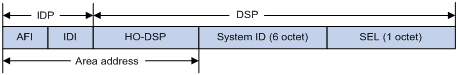
As shown in Figure 1, an NSAP address consists of the Initial Domain Part (IDP) and the Domain Specific Part (DSP). The IDP is equal to the network ID of an IP address, and the DSP is equal to the subnet and host ID.
The IDP includes the Authority and Format Identifier (AFI) and the Initial Domain Identifier (IDI).
The DSP includes the High Order Part of DSP (HO-DSP), System ID and SEL, where the HO-DSP identifies the area, the System ID identifies the host, and the SEL identifies the type of service.
The IDP and DSP are variable in length. The length of an NSAP address varies from 8 bytes to 20 bytes.
Figure 1 NSAP address format
· Area address
The area address comprises the IDP and the HODSP of the DSP, which identify the area and the routing domain. Different routing domains cannot have the same area address.
Typically, a router only needs one area address, and all nodes in the same routing domain must share the same area address. However, a router can have three area addresses at most to support smooth area merging, partitioning and switching.
· System ID
A system ID identifies a host or router uniquely. It has a fixed length of 48 bits (6 bytes).
The system ID of a router can be generated from the Router ID. For example, a router uses the IP address 168.10.1.1 of Loopback 0 as the Router ID. The system ID in IS-IS can be obtained in the following ways:
¡ Extend each decimal number of the IP address to 3 digits by adding 0s from the left, like 168.010.001.001.
¡ Divide the extended IP address into 3 sections with 4 digits in each section to get the system ID 1680.1000.1001.
If you use other methods to define a system ID, always make sure that it can uniquely identify a host or router.
· SEL
The NSAP Selector (SEL), or the N-SEL, is similar to the protocol identifier in IP. Different transport layer protocols correspond to different SELs. All SELs in IP are 00.
· Routing method
Because the area information is identified in IS-IS addresses, a Level-1 router can easily identify packets destined to other areas.
¡ A Level-1 router makes routing decisions based on the system ID. If the destination is not in the area, the packet is forwarded to the nearest Level-1-2 router.
¡ A Level-2 router routes packets across areas according to the area address.
NET
A network entity title (NET) indicates the network layer information of an IS and does not include transport layer information. It is a special NSAP address with the SEL being 0. The length of the NET is equal to the NSAP and is in the range 8 bytes to 20 bytes.
A NET comprises the following parts:
· Area ID—Its length is in the range of 1 to 13 bytes.
· System ID—A system ID uniquely identifies a host or router in the area and has a fixed 6-byte length.
· SEL—It has a value of 0 and a fixed 1-byte length.
For example, a NET is ab.cdef.1234.5678.9abc.00, where area ID is ab.cdef, system ID is 1234.5678.9abc, and SEL is 00.
Typically, a router only needs one NET, but it can have three NETs at most for smooth area merging and partitioning. When you configure multiple NETs, make sure their system IDs are the same.
IS-IS area
Two-level hierarchy
IS-IS has a two-level hierarchy to support large scale networks. A large scale routing domain is divided into multiple Areas. Typically, a Level-1 router is deployed within an area, a Level-2 router is deployed between areas, and a Level-1-2 router is deployed between Level-1 and Level-2 routers.
Level-1 and Level-2
· Level-1 router
A Level-1 router establishes neighbor relationships with Level-1 and Level-1-2 routers in the same area. The LSDB maintained by the Level-1 router contains the local area routing information. It directs the packets destined for an outside area to the nearest Level-1-2 router.
· Level-2 router
A Level-2 router establishes neighbor relationships with the Level-2 and Level-1-2 routers in the same or in different areas. It maintains a Level-2 LSDB which contains inter-area routing information. All the Level-2 and Level-1-2 routers must be contiguous to form the backbone of a routing domain.
· Level-1-2 router
A router with both Level-1 and Level-2 router functions is a Level-1-2 router. It can establish Level-1 neighbor relationships with the Level-1 and Level-1-2 routers in the same area, or establish Level-2 neighbor relationships with the Level-2 and Level-1-2 routers in different areas. A Level-1 router must be connected to other areas through a Level-1-2 router. The Level-1-2 router maintains two LSDBs, where the Level-1 LSDB is for routing within the area, and the Level-2 LSDB is for routing between areas.
|
|
NOTE: · The Level-1 routers in different areas can not establish neighbor relationships. · The neighbor relationship establishment of Level-2 routers has nothing to do with area. |
Figure 2 shows an IS-IS network topology. Area 1 comprises a set of Level-2 routers and is the backbone. The other four areas are non-backbone areas connected to the backbone through Level-1-2 routers.
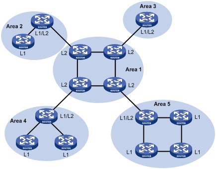
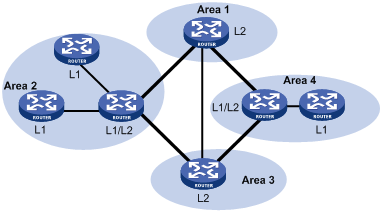
Figure 3 shows another IS-IS topology. The Level-1-2 routers connect to the Level-1 and Level-2 routers, and form the IS-IS backbone together with the Level-2 routers. No area is defined as the backbone in this topology. The backbone comprises all contiguous Level-2 and Level-1-2 routers which can reside in different areas.
|
|
NOTE: The IS-IS backbone does not need to be a specific Area. |
Both the Level-1 and Level-2 routers use the SPF algorithm to generate the shortest path tree (SPT).
Route leaking
An IS-IS routing domain is comprised of only one Level-2 area and multiple Level-1 areas. A Level-1 area consists of a group of Level-1 routers and is connected with a Level-2 area rather than other Level-1 areas.
The routing information of a Level-1 area is sent to the Level-2 area through the Level-1-2 router; therefore, the Level-2 router knows the routing information of the entire IS-IS routing domain. But the Level-1-2 router does not share the information of other Level-1 areas and the Level-2 area with the Level-1 area by default.
Since a Level-1 router simply sends packets destined for other areas to the nearest Level-1-2 router, this may cause that the best paths cannot be selected. To solve this problem, route leaking was introduced. A Level-2 router can advertise Level-2 routing information to a specified Level-1 area. By having the routing information of other areas, a Level-1 router in the area can make a better routing decision for a packet to another area.
IS-IS network type
Network types
IS-IS supports the following network types:
· Broadcast network, such as Ethernet and Token-Ring.
· Point-to-point network, such as PPP and HDLC.
|
|
NOTE: For a Non-Broadcast Multi-Access (NBMA) interface, such as an ATM interface, you need to configure subinterfaces for it and configure the interface type for the subinterfaces as point-to-point or broadcast. IS-IS cannot run on point to multipoint (P2MP) links. |
DIS and pseudonodes
On an IS-IS broadcast network, a router is elected as the Designated Intermediate System (DIS).
The Level-1 and Level-2 DISs are elected respectively. You can assign different priorities for different level DIS elections. The higher a router’s priority is, the more likely the router becomes the DIS. If multiple routers with the same highest DIS priority exist, the one with the highest SNPA (Subnetwork Point of Attachment) address (MAC address on a broadcast network) will be elected. A router can be the DIS for different levels.
IS-IS DIS election differs from OSPF DIS election in that:
· A router with priority 0 can also participate in the DIS election.
· When a router is added to the network and becomes the new DIS, an LDP flooding process is triggered.
As shown in Figure 4, the same level routers on a network including non-DIS routers establish adjacencies with each other.
Figure 4 DIS in the IS-IS broadcast network
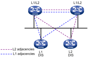
The DIS creates and updates pseudonodes as well as generates their LSPs to describe all routers on the network.
A pseudonode represents a virtual node on the broadcast network. It is not a real router. In IS-IS, it is identified by the system ID of the DIS and a one-byte Circuit ID (a non zero value).
Using pseudonodes can reduce the resources consumed by SPF and simplify network topology.
|
|
NOTE: On IS-IS broadcast networks, all routers are adjacent with each other. However, the DIS is responsible for the synchronization of their LSDBs. |
IS-IS PDUs
PDU header format
IS-IS packets are encapsulated into link layer frames. The Protocol Data Unit (PDU) consists of two parts, the headers and the variable length fields. The headers comprise the PDU common header and the PDU specific header. All PDUs have the same PDU common header. The specific headers vary by PDU type.
Figure 5 PDU format
![]()
Common header format
Figure 6 shows the PDU common header format.
Figure 6 PDU common header format
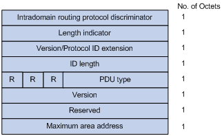
· Intradomain Routing Protocol Discriminator—Set to 0x83.
· Length Indicator—Length of the PDU header in bytes, including both common and specific headers.
· Version/Protocol ID Extension—Set to 1(0x01).
· ID Length—Length of the NSAP address and NET ID.
· R(Reserved)—Set to 0.
· PDU Type—For detailed information, see Table 1.
· Version—Set to 1(0x01).
· Maximum Area Address—Maximum number of area addresses supported.
Table 1 PDU type
|
Type |
PDU Type |
Acronym |
|
15 |
Level-1 LAN IS-IS hello PDU |
L1 LAN IIH |
|
16 |
Level-2 LAN IS-IS hello PDU |
L2 LAN IIH |
|
17 |
Point-to-Point IS-IS hello PDU |
P2P IIH |
|
18 |
Level-1 Link State PDU |
L1 LSP |
|
20 |
Level-2 Link State PDU |
L2 LSP |
|
24 |
Level-1 Complete Sequence Numbers PDU |
L1 CSNP |
|
25 |
Level-2 Complete Sequence Numbers PDU |
L2 CSNP |
|
26 |
Level-1 Partial Sequence Numbers PDU |
L1 PSNP |
|
27 |
Level-2 Partial Sequence Numbers PDU |
L2 PSNP |
Hello PDU
Hello packets are used by routers to establish and maintain neighbor relationships. A hello packet is also an IS-to-IS hello PDU (IIH). For broadcast networks, the Level-1 routers use the Level-1 LAN IIHs; and the Level-2 routers use the Level-2 LAN IIHs. The P2P IIHs are used on point-to-point networks.
Figure 7 illustrates the hello packet format in broadcast networks, where the blue fields are the common header.
Figure 7 L1/L2 LAN IIH format
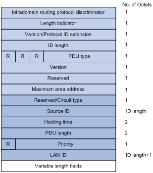
· Reserved/Circuit Type—The first 6 bits are reserved with a value of 0. The last 2 bits indicate the router type. 00 means reserved, 01 indicates L1, 10 indicates L2, and 11 indicates L1/2.
· Source ID—System ID of the router advertising the hello packet.
· Holding Time—If no hello packets are received from the neighbor within the holding time, the neighbor is considered down.
· PDU Length—Total length of the PDU in bytes.
· Priority—DIS priority.
· LAN ID—Includes the system ID and a one-byte pseudonode ID.
Figure 8 shows the hello packet format on the point-to-point networks.
Figure 8 P2P IIH format
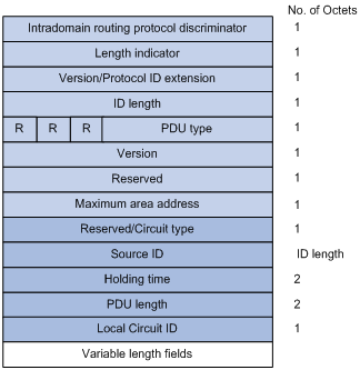
Instead of the priority and LAN ID fields in the LAN IIH, the P2P IIH has a Local Circuit ID field.
LSP
The Link State PDUs (LSP) carry link state information. LSP involves two types: Level-1 LSP and Level-2 LSP. The Level-2 LSPs are sent by the Level-2 routers, and the Level-1 LSPs are sent by the Level-1 routers. The level-1-2 router can send both types of LSPs.
The two types of LSPs have the same format, as shown in Figure 9.
Figure 9 L1/L2 LSP format
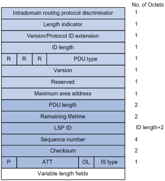
· PDU Length—Total length of the PDU in bytes.
· Remaining Lifetime—LSP remaining lifetime in seconds.
· LSP ID—Consists of the system ID, the pseudonode ID (one byte) and the LSP fragment number (one byte).
· Sequence Number—LSP sequence number.
· Checksum—LSP checksum.
· P (Partition Repair)—Only for L2 LSPs. It indicates whether the router supports partition repair.
· ATT (Attachment)—Generated by a L1/L1 router for L1 LSPs only. It indicates that the router generating the LSP is connected to multiple areas.
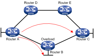
· OL (LSDB Overload)—Indicates that the LSDB is not complete because the router has run out of memory. Other routers will not send packets to the overloaded router, except packets destined to the networks directly connected to the router. For example, in Figure 10, Router A forwards packets to Router C through Router B. Once other routers know the OL field of LSPs from Router B is set to 1, Router A will send packets to Router C via Router D and Router E, but still send to Router B packets destined to the network directly connected to Router B.
· IS Type—Type of the router generating the LSP.
SNP
A sequence number PDU (SNP) acknowledges the latest received LSPs. It is similar to an Acknowledge packet, but more efficient.
SNP involves Complete SNP (CSNP) and Partial SNP (PSNP), which are further divided into Level-1 CSNP, Level-2 CSNP, Level-1 PSNP and Level-2 PSNP.
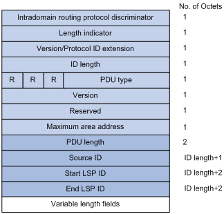
CSNP covers the summary of all LSPs in the LSDB to synchronize the LSDB between neighboring routers. On broadcast networks, CSNP is sent by the DIS periodically (10s by default). On point-to-point networks, CSNP is only sent during the adjacency establishment.
Figure 11 L1/L2 CSNP format
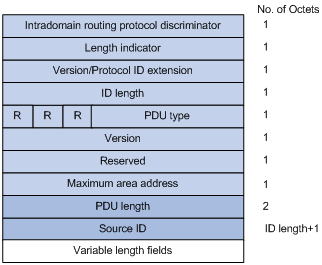
PSNP only contains the sequence numbers of one or multiple latest received LSPs. It can acknowledge multiple LSPs at one time. When LSDBs are not synchronized, a PSNP is used to request new LSPs from neighbors.
Figure 12 L1/L2 PSNP format
CLV
The variable fields of PDU comprise multiple Code-Length-Value (CLV) triplets.
Figure 13 CLV format
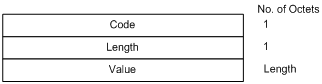
Table 2 shows that different PDUs contain different CLVs. Code 1 to 10 of CLV are defined in ISO 10589 (code 3 and 5 are not shown in the table), and others are defined in RFC 1195.
Table 2 CLV name and the corresponding PDU type
|
CLV Code |
Name |
PDU Type |
|
1 |
Area Addresses |
IIH, LSP |
|
2 |
IS Neighbors (LSP) |
LSP |
|
4 |
Partition Designated Level2 IS |
L2 LSP |
|
6 |
IS Neighbors (MAC Address) |
LAN IIH |
|
7 |
IS Neighbors (SNPA Address) |
LAN IIH |
|
8 |
Padding |
IIH |
|
9 |
LSP Entries |
SNP |
|
10 |
Authentication Information |
IIH, LSP, SNP |
|
128 |
IP Internal Reachability Information |
LSP |
|
129 |
Protocols Supported |
IIH, LSP |
|
130 |
IP External Reachability Information |
L2 LSP |
|
131 |
Inter-Domain Routing Protocol Information |
L2 LSP |
|
132 |
IP Interface Address |
IIH, LSP |
Supported IS-IS features
Multiple instances and processes
IS-IS supports multiple instances and processes. Multiple processes allow a IS-IS process to work in concert with a group of interfaces. A router can run multiple IS-IS processes, and each process corresponds to a unique group of interfaces.
For routers supporting VPN, each IS-IS process is associated with a VPN instance. The VPN instance is also associated with interfaces of the process.
Active/Standby failover
The router supports active/standby failover for IS-IS. The data is copied from the active main board (AMB) to the standby main board (SMB). Whenever the AMB is down, the SMB can switch to the active status to run IS-IS.
The router supports only the Graceful Restart (GR) backup mode. GR backs up only the configuration of IS-IS. After active/standby failover, IS-IS performs GR to synchronize the LSDB with neighbors.
IS-IS Graceful Restart
GR ensures the continuity of packet forwarding when a routing protocol restarts or an active/standby switchover occurs:
· GR Restarter—Graceful restarting router. It must be GR capable.
· GR Helper—A neighbor of the GR Restarter. It helps the GR Restarter to complete the GR process.
After an IS-IS GR Restarter restarts, it must complete the following tasks to synchronize the LSDB with its neighbors.
· Obtain IS-IS neighbor information without changing adjacencies.
· Obtain the LSDB.
To do so, the GR Restarter sends an OSPF GR signal to GR Helpers so that the GR Helpers keep their adjacencies with the GR Restarter, and restores the neighbor table after receiving responses from neighbors. The GR Restarter then synchronizes the LSDB with all GR capable neighbors, calculates routes, updates its routing table and forwarding table, and removes stale routes. The IS-IS routing convergence is complete.
IS-IS NSR
Non-stop Routing (NSR) is a new feature that overcomes the application limit of GR. It backs up IS-IS link state information from the AMB to the SMB. When an active/standby switchover occurs, NSR can complete link state recovery and route re-generation without requiring the cooperation of other routers.
IS-IS TE
IS-IS Traffic Engineering (TE) creates and maintains the Label Switched Path (LSP).
When creating the Constraint-based Routed LSP (CR LSP), MPLS needs to get the traffic attribute information of all links in the local area. The Traffic Engineering information of links is obtained from IS-IS.
|
|
NOTE: For detailed configuration of the IS-IS TE, see MPLS Configuration Guide. |
Management tag
Management tag simplifies routing information management by carrying the management information of the IP address prefixes (to control route redistribution from other routing protocols) and BGP community and extended community attributes.
LSP fragment extension
IS-IS advertises link state information by flooding LSPs. Because one LSP carries a limited amount of link state information, IS-IS fragments LSPs. Each LSP fragment is uniquely identified by a combination of the System ID, Pseudonode ID (0 for a common LSP or a non-zero value for a Pseudonode LSP), and LSP Number (LSP fragment number) of the node or pseudo node that generated the LSP. The one-byte LSP Number field, allowing a maximum of only 256 fragments to be generated by an IS-IS router, limits the amount of link information that the IS-IS router can advertise.
The LSP fragment extension feature allows an IS-IS router to generate more LSP fragments. Up to 50 additional virtual systems can be configured on the router, and each virtual system is capable of generating 256 LSP fragments to enable the IS-IS router to generate up to 13056 LSP fragments.
· Terms
¡ Originating System
It is the router actually running IS-IS. After LSP fragment extension is enabled, additional virtual systems can be configured for the router. Originating system is the actual IS-IS process that originally runs.
¡ System ID
System ID of the originating system.
¡ Additional System ID
Additional virtual system IDs are configured for the IS-IS router after LSP fragment extension is enabled. Each additional system ID can generate 256 LSP fragments. Both the additional system ID and the system ID must be unique in the entire routing domain.
· Virtual System
A virtual system is identified by an additional system ID and generates extended LSP fragments.
· Original LSP
It is the LSP generated by the originating system. The system ID in its LSP ID field is the system ID of the originating system.
· Extended LSP
Extended LSPs are generated by virtual systems. The system ID in its LSP ID field is the virtual system ID.
After additional system IDs are configured, an IS-IS router can advertise more link state information in extended LSP fragments. Each virtual system can be considered a virtual router. An extended LSP fragment is advertised by a virtual system identified by an additional system ID.
· Operation modes
The LSP fragment extension feature operates in the following modes:
¡ Mode-1
Applicable to a network where some routers do not support LSP fragment extension. In this mode, adjacencies are formed between the originating system and virtual systems, with the link cost from the originating system to each virtual system as 0. Each virtual system acts as a router connected to the originating system in the network, but the virtual systems are reachable through the originating system only. The IS-IS routers not supporting LSP fragment extension can operate properly without modifying the extended LSP fragments received, but some limitation is imposed on the link state information in the extended LSP fragments advertised by the virtual systems.
¡ Mode-2
Applicable to a network where all the routers support LSP fragment extension. In this mode, all the IS-IS routers know which virtual system belongs to which originating system; no limitation is imposed on the link state information of the extended LSP fragments advertised by the virtual systems.
The operation mode of LSP fragment extension is configured based on area and routing level. Mode-1 allows the routers supporting and not supporting LSP fragment extension to interoperate with each other, but it restricts the link state information in the extended fragments. Mode-2 does not restrict the link state information in the extended fragments, and is recommended for an area where all the routers are at the same routing level and support LSP fragment extension.
Dynamic host name mapping mechanism
The dynamic host name mapping mechanism provides the mappings between the host names and the system IDs for the IS-IS routers. The dynamic host name information is announced in the dynamic host name CLV of an LSP.
This mechanism also provides the mapping between a host name and the DIS of a broadcast network, which is announced in the dynamic host name TLV of a pseudonode LSP.
A host name is easier to remember than a system ID. After enabling this feature on the router, you can see the host names instead of system IDs using the display command.
BFD
|
|
NOTE: For more information about BFD, see High Availability Configuration Guide. |
Bidirectional forwarding detection (BFD) provides a single mechanism to quickly detect any link failures between IS-IS neighbors to reduce network convergence time.
Protocols and standards
· ISO 10589 ISO IS-IS Routing Protocol
· ISO 9542 ES-IS Routing Protocol
· ISO 8348/Ad2 Network Services Access Points
· RFC 1195, Use of OSI IS-IS for Routing in TCP/IP and Dual Environments
· RFC 2763, Dynamic Hostname Exchange Mechanism for IS-IS
· RFC 2966, Domain-wide Prefix Distribution with Two-Level IS-IS
· RFC 2973, IS-IS Mesh Groups
· RFC 3277, IS-IS Transient Blackhole Avoidance
· RFC 3358, Optional Checksums in ISIS
· RFC 3373, Three-Way Handshake for IS-IS Point-to-Point Adjacencies
· RFC 3567, Intermediate System to Intermediate System (IS-IS) Cryptographic Authentication
· RFC 3719, Recommendations for Interoperable Networks using IS-IS
· RFC 3786, Extending the Number of IS-IS LSP Fragments Beyond the 256 Limit
· RFC 3787, Recommendations for Interoperable IP Networks using IS-IS
· RFC 3784, IS-IS extensions for Traffic Engineering
· RFC 3847, Restart signaling for IS-IS
IS-IS configuration task list
Complete the following tasks to configure IS-IS:
|
Task |
Remarks |
|
|
Required |
||
|
Required |
||
|
Required |
||
|
Optional |
||
|
Required |
||
|
Optional |
||
|
Optional |
||
|
Optional |
||
|
Optional |
||
|
Optional |
||
|
Optional |
||
|
Specifying intervals for sending IS-IS hello and CSNP packets |
Optional |
|
|
Optional |
||
|
Optional |
||
|
Optional |
||
|
Optional |
||
|
Optional |
||
|
Optional |
||
|
Optional |
||
|
Optional |
||
|
Optional |
||
|
Optional |
||
|
Optional |
||
|
Optional |
||
|
Optional |
||
|
Optional |
||
|
Optional |
||
|
Optional |
||
|
Optional |
||
|
Optional |
||
Configuring IS-IS basic functions
Configuration prerequisites
Before the configuration, complete the following tasks:
· Configure the link layer protocol.
· Configure an IP address for each interface, and make sure all neighboring nodes are reachable to each other at the network layer.
Enabling IS-IS
To enable IS-IS:
|
Step |
Command |
Remarks |
|
1. Enter system view. |
system-view |
N/A |
|
2. Enable the IS-IS routing process and enter its view. |
isis [ process-id ] [ vpn-instance vpn-instance-name ] |
Not enabled by default |
|
3. Assign a network entity title (NET). |
network-entity net |
Not assigned by default |
|
4. Return to system view. |
quit |
N/A |
|
5. Enter interface view. |
interface interface-type interface-number |
N/A |
|
6. Enable an IS-IS process on the interface. |
isis enable [ process-id ] |
Disabled by default |
Configuring the IS level and circuit level
If only one area is available, perform the following operations:
· Configure the IS level of all routers as Level-1 or Level-2 rather than different levels because the routers do not need to maintain two identical LSDBs.
· Configure the IS level as Level-2 on all routers in an IP network for scalability.
For an interface of a Level-1 (or Level-2) router, the circuit level can only be Level-1 (or Level-2). For an interface of a Level-1-2 router, the default circuit level is Level-1-2; if the router only needs to form Level-1 (or Level-2) neighbor relationships, you can configure the circuit level for its interfaces as Level-1 (or Level-2) to limit neighbor relationship establishment.
To configure the IS level and circuit level:
|
Step |
Command |
Remarks |
|
1. Enter system view. |
system-view |
N/A |
|
2. Enter IS-IS view. |
isis [ process-id ] [ vpn-instance vpn-instance-name ] |
N/A |
|
3. Specify the IS level. |
is-level { level-1 | level-1-2 | level-2 } |
Optional. The default is Level-1-2. |
|
4. Return to system view. |
quit |
N/A |
|
5. Enter interface view. |
interface interface-type interface-number |
N/A |
|
6. Specify the circuit level. |
isis circuit-level [ level-1 | level-1-2 | level-2 ] |
Optional. The default is Level-1-2. |
Configuring the network type of an interface as P2P
Interfaces with different network types operate differently. For example, broadcast interfaces on a network must elect the DIS and flood CSNP packets to synchronize the LSDBs, but P2P interfaces on a network do not need to elect the DIS and have a different LSDB synchronization mechanism.
If only two routers exist on a broadcast network, configure the network type of attached interfaces as P2P to avoid DIS election and CSNP flooding, saving network bandwidth and speeding up network convergence.
To configure the network type of an interface:
|
Step |
Command |
Remarks |
|
1. Enter system view. |
system-view |
N/A |
|
2. Enter interface view. |
interface interface-type interface-number |
N/A |
|
3. Configure the network type for the interface as P2P. |
isis circuit-type p2p |
Optional. By default, the network type of an interface depends on the physical media. |
|
|
NOTE: You can only perform this configuration for a broadcast network with only two attached routers. |
Configuring IS-IS routing information control
Configuration prerequisites
Before the configuration, complete the following tasks:
· Configure network layer addresses for interfaces, and make sure that all neighboring nodes are reachable to each other at the network layer.
· Enable IS-IS.
Configuring IS-IS link cost
The IS-IS cost of an interface is determined in the following order:
· IS-IS cost specified in interface view.
· IS-IS cost specified in system view. The cost is applied to the interfaces associated to the IS-IS process.
· Automatically calculated cost—When the cost style is wide or wide-compatible, IS-IS automatically calculates the cost using the formula: interface cost = (bandwidth reference value/interface bandwidth) ×10. When the cost style is of another type: if the interface bandwidth does not exceed 10 Mbps, the interface cost equals 60; if the interface bandwidth does not exceed 100 Mbps, the interface cost equals 50; if the interface bandwidth does not exceed 155 Mbps, the interface cost equals 40; if the interface bandwidth does not exceed 622 Mbps, the interface cost equals 30; if the interface bandwidth does not exceed 2500 Mbps, the interface cost equals 20; if the interface bandwidth exceeds 2500 Mbps, the interface cost equals 10.
If none of the above costs is used, a default cost of 10 applies.
Configuring an IS-IS cost for an interface
To configure a cost for an interface:
|
Step |
Command |
Remarks |
|
1. Enter system view. |
system-view |
N/A |
|
2. Enter IS-IS view. |
isis [ process-id ] [ vpn-instance vpn-instance-name ] |
N/A |
|
3. Specify an IS-IS cost style. |
cost-style { narrow | wide | wide-compatible | { compatible | narrow-compatible } [ relax-spf-limit ] } |
Optional. narrow by default. |
|
4. Return to system view. |
quit |
N/A |
|
5. Enter interface view. |
interface interface-type interface-number |
N/A |
|
6. Specify a cost for the interface. |
isis cost value [ level-1 | level-2 ] |
Optional. By default, no cost is specified for the interface. |
Configuring a global IS-IS cost
To configure a global IS-IS cost:
|
Step |
Command |
Remarks |
|
1. Enter system view. |
system-view |
N/A |
|
2. Enter IS-IS view. |
isis [ process-id ] [ vpn-instance vpn-instance-name ] |
N/A |
|
3. Specify an IS-IS cost style. |
cost-style { narrow | wide | wide-compatible | { compatible | narrow-compatible } [ relax-spf-limit ] } |
Optional. narrow by default. |
|
4. Specify a global IS-IS cost. |
circuit-cost value [ level-1 | level-2 ] |
By default, no global cost is specified. |
Enabling automatic IS-IS cost calculation
To enable automatic IS-IS cost calculation:
|
Step |
Command |
Remarks |
|
1. Enter system view. |
system-view |
N/A |
|
2. Enter IS-IS view. |
isis [ process-id ] [ vpn-instance vpn-instance-name ] |
N/A |
|
3. Specify an IS-IS cost style. |
cost-style { wide | wide-compatible } |
narrow by default |
|
4. Enable automatic IS-IS cost calculation. |
auto-cost enable |
Disabled by default |
|
5. Configure a bandwidth reference value for automatic IS-IS cost calculation. |
bandwidth-reference value |
Optional 100 Mbps by default |
Specifying a priority for IS-IS
A router may run multiple routing protocols. When routes to the same destination are found by multiple routing protocols, the route learned by the protocol with the highest priority wins. You can reference a routing policy to specify a priority for specific routes. For information about routing policy, see the chapter “Configuration routing policies.”
To configure the priority of IS-IS.
|
Step |
Command |
Remarks |
|
1. Enter system view. |
system-view |
N/A |
|
2. Enter IS-IS view. |
isis [ process-id ] [ vpn-instance vpn-instance-name ] |
N/A |
|
3. Specify a priority for IS-IS. |
preference { route-policy route-policy-name | preference } * |
15 by default |
Configuring the maximum number of equal cost routes
If multiple equal cost routes reach the same destination, the traffic can be load balanced to enhance efficiency.
To configure the maximum number of equal cost routes:
|
Step |
Command |
|
1. Enter system view. |
system-view |
|
2. Enter IS-IS view. |
isis [ process-id ] [ vpn-instance vpn-instance-name ] |
|
3. Specify the maximum number of equal cost routes for load balancing. |
maximum load-balancing number |
Configuring IS-IS route summarization
This task allows you to configure a summary route, so routes falling into the network range of the summary route are summarized into one route for advertisement. Doing so can reduce the size of routing tables, as well as the scale of LSP and LSDB. Both IS-IS routes and redistributed routes can be summarized.
To configure route summarization:
|
Step |
Command |
Remarks |
|
1. Enter system view. |
system-view |
N/A |
|
2. Enter IS-IS view. |
isis [ process-id ] [ vpn-instance vpn-instance-name ] |
N/A |
|
3. Configure IS-IS route summarization. |
summary ip-address { mask | mask-length } [ avoid-feedback | generate_null0_route | tag tag | [ level-1 | level-1-2 | level-2 ] ] * |
By default, no route summarization is configured. |
|
|
NOTE: · The cost of the summary route is the lowest one among the costs of summarized routes. · The router summarizes only the routes in the locally generated LSPs. |
Advertising a default route
A router running IS-IS cannot redistribute any default route or advertise a default route to neighbors. You can use the following commands to advertise a default route of 0.0.0.0/0 to the same level neighbors.
To advertise a default route:
|
Step |
Command |
Remarks |
|
1. Enter system view. |
system-view |
N/A |
|
2. Enter IS-IS view. |
isis [ process-id ] [ vpn-instance vpn-instance-name ] |
N/A |
|
3. Advertise a default route. |
default-route-advertise [ route-policy route-policy-name | [ level-1 | level-1-2 | level-2 ] ] * |
By default, the function is disabled. |
|
|
NOTE: The default route is only advertised to routers at the same level. You can use a routing policy to generate the default route only when a local routing entry is matched by the policy. |
Configuring IS-IS route redistribution
Redistributing large numbers of routes on a router may affect the performance of other routers in the network. If this happens, you can configure a limit on the number of redistributed routes in order to limit the number of routes to be advertised.
To configure IS-IS route redistribution from other routing protocols:
|
Step |
Command |
Remarks |
|
1. Enter system view. |
system-view |
N/A |
|
2. Enter IS-IS view. |
isis [ process-id ] [ vpn-instance vpn-instance-name ] |
N/A |
|
3. Redistribute routes from another routing protocol. |
import-route protocol [ process-id | all-processes | allow-ibgp ] [ cost cost | cost-type { external | internal } | [ level-1 | level-1-2 | level-2 ] | route-policy route-policy-name | tag tag ] * |
By default, no route is redistributed. If no level is specified, routes are redistributed into the Level-2 routing table by default. |
|
4. Configure the maximum number of redistributed Level 1/Level 2 IPv4 routes. |
import-route limit number |
Optional. |
|
|
NOTE: Only active routes can be redistributed. Use the display ip routing-table protocol command to display route state information. |
Configuring IS-IS route filtering
You can reference a configured ACL, IP prefix list, or routing policy to filter routes calculated from the received LSPs and the routes redistributed from other routing protocols.
Filtering routes calculated from received LSPs
IS-IS saves the LSPs received from neighbors in the LSDB, uses the SPF algorithm to calculate the shortest path tree with itself as the root, and installs the routes into the IS-IS routing table.
By referencing a configured ACL, IP prefix list or routing policy, you can filter the calculated routes. Only the routes matching the filter can be added into the IS-IS routing table.
To filter routes calculated from received LSPs:
|
Step |
Command |
Remarks |
|
1. Enter system view. |
system-view |
N/A |
|
2. Enter IS-IS view. |
isis [ process-id ] [ vpn-instance vpn-instance-name ] |
N/A |
|
3. Filter routes calculated from received LSPs. |
filter-policy { acl-number | ip-prefix ip-prefix-name | route-policy route-policy-name } import |
By default, no filtering is configured. |
Filtering redistributed routes
IS-IS can redistribute routes from other routing protocols or other IS-IS processes, add them into the IS-IS routing table and advertise them in LSPs.
By reference a configured ACL, IP prefix list or routing policy, you can filter redistributed routes and only the routes matching the filter can be added into the IS-IS routing table and advertised to neighbors.
To configure the filtering of redistributed routes:
|
Step |
Command |
Remarks |
|
1. Enter system view. |
system-view |
N/A |
|
2. Enter IS-IS view. |
isis [ process-id ] [ vpn-instance vpn-instance-name ] |
N/A |
|
3. Configure the filtering of routes redistributed from another routing protocol or IS-IS process. |
filter-policy { acl-number | ip-prefix ip-prefix-name | route-policy route-policy-name } export [ protocol [ process-id ] ] |
Not configured by default |
Configuring IS-IS route leaking
With IS-IS route leaking enabled, the Level-1-2 router can advertise the routing information of other Level-1 areas and Level-2 area routing information to Level-1 routers.
To configure IS-IS route leaking:
|
Step |
Command |
Remarks |
|
1. Enter system view. |
system-view |
N/A |
|
2. Enter IS-IS view. |
isis [ process-id ] [ vpn-instance vpn-instance-name ] |
N/A |
|
3. Enable IS-IS route leaking. |
import-route isis level-2 into level-1 [ filter-policy { acl-number | ip-prefix ip-prefix-name | route-policy route-policy-name } | tag tag ] * |
Disabled by default |
|
|
NOTE: · If a filter policy is specified, only routes passing it can be advertised into Level-1 area. · You can specify a routing policy in the import-route isis level-2 into level-1 command to filter routes from Level-2 to Level-1. Other routing policies specified for route reception and redistribution does not affect the route leaking. |
Tuning and optimizing IS-IS networks
Configuration prerequisites
Before the configuration, complete the following tasks:
· Configure IP addresses for interfaces, and make sure that all neighboring nodes are reachable to each other at the network layer.
· Enable IS-IS.
Specifying intervals for sending IS-IS hello and CSNP packets
To configure intervals for sending IS-IS hello and CSNP packets:
|
Step |
Command |
Remarks |
|
1. Enter system view. |
system-view |
N/A |
|
2. Enter interface view. |
interface interface-type interface-number |
N/A |
|
3. Specify the interval for sending hello packets. |
isis timer hello seconds [ level-1 | level-2 ] |
Optional 10 seconds by default |
|
4. Specify the interval for sending CSNP packets on the DIS of a broadcast network. |
isis timer csnp seconds [ level-1 | level-2 ] |
Optional 10 seconds by default |
|
|
NOTE: The interval between hello packets sent by the DIS is 1/3 the hello interval set with the isis timer hello command. |
Specifying the IS-IS hello multiplier
If a neighbor receives no hello packets from the router within the advertised hold time, it considers the router down and recalculates the routes. The hold time is the hello multiplier multiplied by the hello interval.
To specify the IS-IS hello multiplier:
|
Step |
Command |
Remarks |
|
1. Enter system view. |
system-view |
N/A |
|
2. Enter interface view. |
interface interface-type interface-number |
N/A |
|
3. Specify the number of hello packets a neighbor must miss before declaring the router is down. |
isis timer holding-multiplier value [ level-1 | level-2 ] |
Optional 3 by default |
|
|
NOTE: On a broadcast link, Level-1 and Level-2 hello packets are advertised separately; therefore, you need to set a hello multiplier for each level. On a P2P link, Level-1 and Level-2 hello packets are advertised in P2P hello packets, and you do not need to specify Level-1 or Level-2. |
Configuring a DIS priority for an interface
On an IS-IS broadcast network, a router should be elected as the DIS at a routing level. You can specify a DIS priority at a level for an interface. The greater the interface’s priority is, the more likely it becomes the DIS. If multiple routers in the broadcast network have the same highest DIS priority, the router with the highest MAC address becomes the DIS.
To specify a DIS priority for an interface:
|
Step |
Command |
Remarks |
|
1. Enter system view. |
system-view |
N/A |
|
2. Enter interface view. |
interface interface-type interface-number |
N/A |
|
3. Specify a DIS priority for the interface. |
isis dis-priority value [ level-1 | level-2 ] |
Optional 64 by default |
Disabling an interface from sending/receiving IS-IS packets
After disabled from sending and receiving hello packets, an interface cannot form any neighbor relationship, but can advertise directly connected networks in LSPs through other interfaces. This can save bandwidth and CPU resources, and ensures other routers know networks directly connected to the interface.
To disable an interface from sending and receiving IS-IS packets:
|
Step |
Command |
Remarks |
|
1. Enter system view. |
system-view |
N/A |
|
2. Enter interface view. |
interface interface-type interface-number |
N/A |
|
3. Disable the interface from sending and receiving IS-IS packets. |
isis silent |
Not disabled by default |
Disabling hello source address check for a PPP interface
On a P2P link, IS-IS verifies the source IP address of the incoming hello packets is in the same network segment as the IP address of the receiving interface. If not, it discards the hello packets, and no neighbor relationship can be established with the peer router.
For a PPP interface, the peer’s IP address may reside on a different network segment. In this case, you can disable the hello source address check for the PPP interface to establish the neighbor relationship with the peer.
To enable neighbor relationships over different network segments:
|
Step |
Command |
Remarks |
|
1. Enter system view. |
system-view |
N/A |
|
2. Enter interface view. |
interface interface-type interface-number |
N/A |
|
3. Disable hello source address check for the PPP interface. |
isis peer-ip-ignore |
The command only applies to the PPP interface. By default, hello source address check is enabled. |
Enabling an interface to send small hello packets
IS-IS messages cannot be fragmented at the IP layer because they are directly encapsulated into frames. Any two IS-IS neighboring routers must negotiate a common MTU. To avoid sending big hellos for saving bandwidth, enable the interface to send small hello packets without CLVs.
To enable an interface to send small hello packets:
|
Step |
Command |
Remarks |
|
1. Enter system view. |
system-view |
N/A |
|
2. Enter interface view. |
interface interface-type interface-number |
N/A |
|
3. Enable the interface to send small hello packets without CLVs. |
isis small-hello |
By default, standard hello packets are sent. |
Configuring LSP parameters
Configuring LSP timers
1. Specify the maximum age of LSPs
Each LSP has an age that decreases in the LSDB. Any LSP with an age of 0 is deleted from the LSDB. You can adjust the age value based on the scale of a network.
To specify the maximum age of LSPs:
|
Step |
Command |
Remarks |
|
1. Enter system view. |
system-view |
N/A |
|
2. Enter IS-IS view. |
isis [ process-id ] [ vpn-instance vpn-instance-name ] |
N/A |
|
3. Specify the maximum LSP age. |
timer lsp-max-age seconds |
Optional 1200 seconds by default |
2. Specify the LSP refresh interval and generation interval
Each router needs to refresh LSPs generated by itself at a configurable interval and send them to other routers to prevent valid routes from being aged out. A smaller refresh interval speeds up network convergence but consumes more bandwidth.
When the network topology changes, for example, a neighbor is down/up, or the interface metric, system ID or area ID is changed, the router generates an LSP after a configurable interval. If such changes occur frequently, excessive LSPs are generated, consuming a large amount of router resources and bandwidth. To solve the problem, you can adjust the LSP generation interval.
To specify the LSP refresh interval and generation interval:
|
Step |
Command |
Remarks |
|
1. Enter system view. |
system-view |
N/A |
|
2. Enter IS-IS view. |
isis [ process-id ] [ vpn-instance vpn-instance-name ] |
N/A |
|
3. Specify the LSP refresh interval. |
timer lsp-refresh seconds |
Optional 900 seconds by default |
|
4. Specify the LSP generation interval. |
timer lsp-generation maximum-interval [ initial-interval [ second-wait-interval ] ] [ level-1 | level-2 ] |
Optional 2 seconds by default |
3. Specify LSP sending intervals
If a change occurs in the LSDB, IS-IS advertises the changed LSP to neighbors. You can specify the minimum interval for sending such LSPs.
On a P2P link, IS-IS requires an advertised LSP be acknowledged. If no acknowledgement is received within a configurable interval, IS-IS will retransmit the LSP.
To configure LSP sending intervals:
|
Step |
Command |
Remarks |
|
|
1. Enter system view. |
system-view |
N/A |
|
|
2. Enter interface view. |
interface interface-type interface-number |
N/A |
|
|
3. Specify the minimum interval for sending LSPs and the maximum LSP number that can be sent at a time. |
isis timer lsp time [ count count ] |
Optional. By default, the minimum interval is 33 milliseconds, and the maximum LSP number that can be sent at a time is 5. |
|
|
4. Specify the LSP retransmission interval on a P2P link. |
isis timer retransmit seconds |
Optional. 5 seconds by default. |
|
|
|
NOTE: Configure a proper LSP retransmission interval to avoid unnecessary retransmissions. |
Specifying LSP lengths
IS-IS messages cannot be fragmented at the IP layer because they are directly encapsulated in frames. IS-IS routers in an area must send LSPs smaller than the smallest interface MTU in this area.
If the IS-IS routers have different interface MTUs, H3C recommends configuring the maximum size of generated LSP packets to be smaller than the smallest interface MTU in this area. Otherwise, the routers have to dynamically adjust the LSP packet size to fit the smallest interface MTU, which takes time and affects other services.
To specify LSP lengths:
|
Step |
Command |
Remarks |
|
1. Enter system view. |
system-view |
N/A |
|
2. Enter IS-IS view. |
isis [ process-id ] [ vpn-instance vpn-instance-name ] |
N/A |
|
3. Specify the maximum length of generated Level-1 LSPs or Level-2 LSPs. |
lsp-length originate size [ level-1 | level-2 ] |
1497 bytes by default |
|
4. Specify the maximum length of received LSPs. |
lsp-length receive size |
1497 bytes by default |
Enabling LSP flash flooding
Because changed LSPs may trigger SPF recalculation, you can enable LSP flash flooding to advertise the changed LSPs before the router recalculates routes. Doing so can speed up network convergence.
To enable LSP flash flooding:
|
Step |
Command |
Remarks |
|
1. Enter system view. |
system-view |
N/A |
|
2. Enter IS-IS view. |
isis [ process-id ] [ vpn-instance vpn-instance-name ] |
N/A |
|
3. Enable LSP flash flooding. |
flash-flood [ flood-count flooding-count | max-timer-interval flooding-interval | [ level-1 | level-2 ] ] * |
Not enabled by default |
Enabling LSP fragment extension
To enable LSP fragment extension:
|
Step |
Command |
Remarks |
|
1. Enter system view. |
system-view |
N/A |
|
2. Enter IS-IS view. |
isis [ process-id ] [ vpn-instance vpn-instance-name ] |
N/A |
|
3. Enable LSP fragment extension and specify the working mode. |
lsp-fragments-extend [ [ level-1 | level-1-2 | level-2 ] | [ mode-1 | mode-2 ] ] * |
Not enabled by default |
|
4. Configure a virtual system ID. |
virtual-system virtual-system-id |
Not configured by default |
Limiting LSP flooding
In well-connected NBMA networks, many P2P links exist. Figure 14 shows a fully meshed network, where Routers A, B, C and D run IS-IS. When Router A generates an LSP, it floods the LSP out GigabitEthernet 1/1/1, GigabitEthernet 1/1/2 and GigabitEthernet 1/1/3. After receiving the LSP from GigabitEthernet 1/1/3, Router D floods it out GigabitEthernet 1/1/1 and GigabitEthernet 1/1/2 to Router B and Router C. However, Router B and Router C have already received the LSP from Router A. LSP flooding consumes extra bandwidth.
Figure 14 Network diagram of a fully meshed network
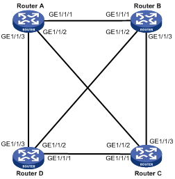
To avoid this, configure some interfaces as a mesh group, configure the blocked interfaces, or both.
· After receiving an LSP, a member interface in a mesh group floods it out the interfaces that does not belong to the mesh group.
· If an interface is blocked, it does not send LSPs unless the neighbor sends LSP requests to it.
Before configuring this task, you must consider redundancy for interfaces in case that LSP packets cannot be flooded due to link failures.
To add an interface into a mesh group and block an interface:
|
Step |
Command |
Remarks |
|
1. Enter system view. |
system-view |
N/A |
|
2. Enter interface view. |
interface interface-type interface-number |
N/A |
|
3. Add the interface to a mesh group or block the interface. |
·
Add the interface to a mesh group: ·
Block the interface: |
Use either approach. By default, the interface neither belongs to any mesh group nor is blocked. |
|
|
NOTE: The mesh group feature takes effect only on P2P interfaces. |
Configuring SPF parameters
When the LSDB changes on a router, a route calculation starts. Frequent route calculations consume a lot of system resources. You can set an appropriate interval for SPF calculations to improve efficiency.
To configure the SPF parameters:
|
Step |
Command |
Remarks |
|
1. Enter system view. |
system-view |
N/A |
|
2. Enter IS-IS view. |
isis [ process-id ] [ vpn-instance vpn-instance-name ] |
N/A |
|
3. Configure the SPF calculation interval. |
timer spf maximum-interval [ initial-interval [ second-wait-interval ] ] |
Optional. The default SPF calculation interval is 10 seconds. |
Setting the LSDB overload bit
By setting the overload bit in sent LSPs, a router informs other routers of a failure that makes it incapable of routing and forwarding packets.
When an IS-IS router cannot record the complete LSDB due to running out of memory or some other reasons, it will calculate wrong routes. To make troubleshooting easier, you can temporarily isolate the router from the IS-IS network by setting the overload bit.
To set the LSDB overload bit:
|
Step |
Command |
Remarks |
|
1. Enter system view. |
system-view |
N/A |
|
2. Enter IS-IS view. |
isis [ process-id ] [ vpn-instance vpn-instance-name ] |
N/A |
|
3. Set the overload bit. |
set-overload [ on-startup [ [ start-from-nbr system-id [ timeout1 [ nbr-timeout ] ] ] | timeout2 ] [ allow { external | interlevel } * ] |
Not set by default |
Configuring system ID to host name mappings
In IS-IS, a system ID identifies a router or host uniquely. A system ID has a fixed length of 6 bytes. When an administrator needs to view IS-IS neighbor information, routing table or LSDB information, using the system IDs in dotted decimal notation is not convenient. To solve it, you can configure the mappings between system IDs and host names since host names are easier to remember and use.
Such mappings can be configured manually or dynamically.
· Using the display isis lsdb command on a router configured with dynamic system ID to host name mapping displays router names rather than system IDs.
· If you configure both dynamic and static system ID to host name mappings on a router, the host name for dynamic system ID to host name mapping applies.
Configuring a static system ID to host name mapping
To configure a static system ID to host name mapping:
|
Step |
Command |
Remarks |
|
1. Enter system view. |
system-view |
N/A |
|
2. Enter IS-IS view. |
isis [ process-id ] [ vpn-instance vpn-instance-name ] |
N/A |
|
3. Configure a system ID to host name mapping for a remote IS. |
is-name map sys-id map-sys-name |
A system ID can only correspond to a host name. |
Configuring dynamic system ID to host name mapping
You need to configure a static system ID to host name mapping for any other router in a network. When a new router is added into the network or a mapping needs to be modified, perform configuration on all routers.
You can configure dynamic system ID to host name mapping. To do so, you must configure a host name for each router in the network. Each router advertises the host name in dynamic host name CLVs to other routers. At last, all routers in the network have all the mappings to generate a mapping table.
In addition, you can configure a name for the DIS in a broadcast network to help check the origin of LSPs in the LSDB.
To configure dynamic system ID to host name mapping:
|
Step |
Command |
Remarks |
|
1. Enter system view. |
system-view |
N/A |
|
2. Enter IS-IS view. |
isis [ process-id ] [ vpn-instance vpn-instance-name ] |
N/A |
|
3. Specify a host name for the router. |
is-name sys-name |
No specified by default. |
|
4. Return to system view. |
quit |
N/A |
|
5. Enter interface view. |
interface interface-type interface-number |
N/A |
|
6. Configure a DIS name. |
isis dis-name symbolic-name |
Optional. Not configured by default. This command takes effect only on a router with dynamic system ID to host name mapping configured. This command is not supported on P2P interfaces. |
Enabling the logging of neighbor state changes
To enable the logging of neighbor state changes:
|
Step |
Command |
Remarks |
|
1. Enter system view. |
system-view |
N/A |
|
2. Enter IS-IS view. |
isis [ process-id ] [ vpn-instance vpn-instance-name ] |
N/A |
|
3. Enable the logging of neighbor state changes. |
log-peer-change |
Enabled by default |
|
|
NOTE: With this feature enabled, the router delivers information about neighbor state changes to the terminal for display. |
Enhancing IS-IS network security
To enhance the security of an IS-IS network, you can configure IS-IS authentication. IS-IS authentication involves neighbor relationship authentication, area authentication and routing domain authentication.
Configuration prerequisites
Before this configuration, complete the following tasks:
· Configure IP addresses for interfaces, and make sure that all neighboring nodes are reachable to each other at the network layer.
· Enable IS-IS.
Configuring neighbor relationship authentication
With neighbor relationship authentication configured, an interface adds the password in the specified mode into hello packets to the peer and checks the password in the received hello packets. If the authentication succeeds, it forms the neighbor relationship with the peer.
The authentication mode and password at both ends must be identical.
To configure neighbor relationship authentication:
|
Step |
Command |
Remarks |
|
1. Enter system view. |
system-view |
N/A |
|
2. Enter interface view. |
interface interface-type interface-number |
N/A |
|
3. Specify the authentication mode and password. |
isis authentication-mode { md5 | simple } password [ level-1 | level-2 ] [ ip | osi ] |
By default, no authentication is configured. |
|
|
NOTE: · The level-1 and level-2 keywords are configurable on an interface that has IS-IS enabled with the isis enable command. · If you configure an authentication mode and a password without specifying a level, the authentication mode and password apply to both Level-1 and Level-2. · If neither ip nor osi is specified, the OSI related fields in LSPs are checked. |
Configuring area authentication
Area authentication enables a router not to install routing information from untrusted routers into the Level-1 LSDB. The router encapsulates the authentication password in the specified mode into Level-1 packets (LSP, CSNP, PSNP) and check the password in received Level-1 packets.
Routers in a common area must have the same authentication mode and password.
To configure area authentication:
|
Step |
Command |
Remarks |
|
1. Enter system view. |
system-view |
N/A |
|
2. Enter IS-IS view. |
isis [ process-id ] [ vpn-instance vpn-instance-name ] |
N/A |
|
3. Specify the area authentication mode and password. |
area-authentication-mode { md5 | simple } password [ ip | osi ] |
By default, no area authentication is configured. |
Configuring routing domain authentication
Routing domain authentication prevents untrusted routing information from entering into a routing domain. A router with the authentication configured encapsulates the password in the specified mode into Level-2 packets (LSP, CSNP, PSNP) and check the password in received Level-2 packets.
All the routers in the backbone must have the same authentication mode and password.
To configure routing domain authentication:
|
Step |
Command |
Remarks |
|
1. Enter system view. |
system-view |
N/A |
|
2. Enter IS-IS view. |
isis [ process-id ] [ vpn-instance vpn-instance-name ] |
N/A |
|
3. Specify the routing domain authentication mode and password. |
domain-authentication-mode { simple | md5 } password [ ip | osi ] |
By default, no routing domain authentication is configured. |
Configuring IS-IS GR
Restarting IS-IS on a router will cause network disconnections and route re-convergence.
With the Graceful Restart (GR) feature, the restarting router (known as the “GR restarter”) can notify the event to its GR capable neighbors. GR capable neighbors (known as the “GR helpers”) will keep their adjacencies with the router within a configurable GR interval. After the restart, the router contacts its neighbors to retrieve its routing table.
During the whole process, the network keeps stable.
To configure GR on the GR Restarter and GR Helper respectively:
|
Step |
Command |
Remarks |
|
1. Enter system view. |
system-view |
N/A |
|
2. Enable IS-IS, and enter IS-IS view. |
isis [ process-id ] [ vpn-instance vpn-instance-name ] |
Disabled by default. |
|
3. Enable the GR capability for IS-IS. |
graceful-restart |
Disabled by default. |
|
4. Set the Graceful Restart interval. |
graceful-restart interval timer |
300 seconds by default. The Graceful Restart interval is set as the holding time in the hello PDUs. Within the interval, the neighbors will keep their adjacency with the GR Restarter. |
|
5. Suppress the SA bit during restart. |
graceful-restart suppress-sa |
Optional. By default, the SA bit is not suppressed. By enabling the GR Restarter to suppress the Suppress-Advertisement (SA) bit in the hello PDUs, the neighbors will still advertise their adjacency with the GR Restarter. |
Configuring IS-IS FRR
|
|
NOTE: · Do not use FRR and BFD at the same time. Otherwise, FRR may fail to take effect. · The automatic backup next hop calculation of FRR and that of TE are mutually exclusive. |
Introduction
When a link fails, the packets on the path are discarded, or a routing loop occurs until IS-IS completes the routing convergence based on the new network topology.
You can enable IS-IS fast reroute (FRR) to reduce traffic recovery time.
Figure 15 Network diagram for IS-IS FRR

In Figure 15, after you enable FRR on Router B, IS-IS automatically calculates or designates a backup next hop when a link failure is detected. In this way, packets are directed to the backup next hop to reduce traffic recovery time. Meanwhile, IS-IS calculates the shortest path based on the new network topology, and forwards packets over the path after network convergence.
You can either enable IS-IS FRR to calculate a backup next hop automatically, or to designate a backup next hop with a routing policy for routes matching specific criteria.
Configuration prerequisites
Before you configure IS-IS FRR, complete the following tasks:
· Configure IP addresses for interfaces, and make sure that all neighboring nodes are reachable at the network layer.
· Enable IS-IS.
Configuring IS-IS FRR to automatically calculate the backup next hop
To configure IS-IS FRR:
|
Step |
Command |
Remarks |
|
1. Enter system view. |
system-view |
N/A |
|
2. Configure the source address of echo packets. |
bfd echo-source-ip ip-address |
Not configured by default |
|
3. Enter IS-IS view. |
isis [ process-id ] [ vpn-instance vpn-instance-name ] |
N/A |
|
4. Enable IS-IS FRR to automatically calculate a backup next hop. |
fast-reroute auto |
Not configured by default |
Configuring IS-IS FRR to designate the backup next hop with a routing policy
You can use the apply fast-reroute backup-interface command to specify a backup next hop in a routing policy for routes matching specific criteria. For more information about the apply fast-reroute backup-interface command and routing policy configurations, see the chapter “Configuring routing policies.”
To configure IS-IS FRR:
|
Step |
Command |
Remarks |
|
1. Enter system view. |
system-view |
N/A |
|
2. Configure the source address of echo packets. |
bfd echo-source-ip ip-address |
Not configured by default |
|
3. Enter IS-IS view. |
isis [ process-id ] [ vpn-instance vpn-instance-name ] |
N/A |
|
4. Enable IS-IS FRR to designate a backup next hop by using a routing policy. |
fast-reroute route-policy route-policy-name |
Not configured by default |
Enabling IS-IS SNMP trap
To enable IS-IS SNMP trap:
|
Step |
Command |
Remarks |
|
1. Enter system view. |
system-view |
N/A |
|
2. Enter IS-IS view. |
isis [ process-id ] [ vpn-instance vpn-instance-name ] |
N/A |
|
3. Enable SNMP trap. |
is-snmp-traps enable |
Enabled by default |
Binding an IS-IS process with MIBs
To bind an IS-IS process with MIBs:
|
Step |
Command |
Remarks |
|
1. Enter system view. |
system-view |
N/A |
|
2. Bind the IS-IS process with MIBs. |
isis mib-binding process-id |
By default, MIBs are bound with IS-IS process 1. |
Configuring BFD for IS-IS
To enable BFD on an IS-IS interface:
|
Step |
Command |
Remarks |
|
1. Enter system view. |
system-view |
N/A |
|
2. Enter interface view. |
interface interface-type interface-number |
N/A |
|
3. Enable IS-IS on the interface. |
isis enable [ process-id ] |
Disabled by default |
|
4. Enable BFD on the IS-IS interface. |
isis bfd enable |
Not enabled by default |
Displaying and maintaining IS-IS
|
Task |
Command |
Remarks |
|
Display brief IS-IS configuration information. |
display isis brief [ process-id | vpn-instance vpn-instance-name ] [ | { begin | exclude | include } regular-expression ] |
Available in any view |
|
Display the status of IS-IS debug switches. |
display isis debug-switches { process-id | vpn-instance vpn-instance-name } [ | { begin | exclude | include } regular-expression ] |
Available in any view |
|
Display the IS-IS Graceful Restart state. |
display isis graceful-restart status [ level-1 | level-2 ] [ process-id | vpn-instance vpn-instance-name ] [ | { begin | exclude | include } regular-expression ] |
Available in any view |
|
Display information about IS-IS enabled interfaces. |
display isis interface [ statistics | [ interface-type interface-number ] [ verbose ] ] [ process-id | vpn-instance vpn-instance-name ] [ | { begin | exclude | include } regular-expression ] |
Available in any view |
|
Display IS-IS LSDB information. |
display isis lsdb [ [ l1 | l2 | level-1 | level-2 ] | [ lsp-id lspid | lsp-name lspname ] | local | verbose ] * [ process-id | vpn-instance vpn-instance-name ] [ | { begin | exclude | include } regular-expression ] |
Available in any view |
|
Display IS-IS mesh group information. |
display isis mesh-group [ process-id | vpn-instance vpn-instance-name ] [ | { begin | exclude | include } regular-expression ] |
Available in any view |
|
Display the host-name-to-system-ID mapping table. |
display isis name-table [ process-id | vpn-instance vpn-instance-name ] [ | { begin | exclude | include } regular-expression ] |
Available in any view |
|
Display IS-IS neighbor information. |
display isis peer [ statistics | verbose ] [ process-id | vpn-instance vpn-instance-name ] [ | { begin | exclude | include } regular-expression ] |
Available in any view |
|
Display IS-IS IPv4 routing information. |
display isis route [ ipv4 ] [ [ level-1 | level-2 ] | verbose ] * [ process-id | vpn-instance vpn-instance-name ] [ | { begin | exclude | include } regular-expression ] |
Available in any view |
|
Display IS-IS SPF calculation log information. |
display isis spf-log [ process-id | vpn-instance vpn-instance-name ] [ | { begin | exclude | include } regular-expression ] |
Available in any view |
|
Display IS-IS statistics. |
display isis statistics [ level-1 | level-1-2 | level-2 ] [ process-id | vpn-instance vpn-instance-name ] [ | { begin | exclude | include } regular-expression ] |
Available in any view |
|
Clear IS-IS process data structure information. |
reset isis all [ process-id | vpn-instance vpn-instance-name ] |
Available in user view |
|
Clear the data structure information of an IS-IS neighbor. |
reset isis peer system-id [ process-id | vpn-instance vpn-instance-name ] |
Available in user view |
IS-IS configuration examples
IS-IS basic configuration
Network requirements
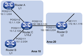
As shown in Figure 16, Router A, B, C and Router D reside in an autonomous system. They are interconnected through IS-IS.
Router A and Router B are Level-1 routers, Router D is a Level-2 router, and Router C is a Level-1-2 router connecting two areas. Router A, Router B, and Router C are in area 10, and Router D is in area 20.
Configuration procedure
1. Configure IP addresses for interfaces. (Details not shown)
2. Configure IS-IS:
# Configure Router A
<RouterA> system-view
[RouterA] isis 1
[RouterA-isis-1] is-level level-1
[RouterA-isis-1] network-entity 10.0000.0000.0001.00
[RouterA-isis-1] quit
[RouterA] interface POS 2/1/1
[RouterA-POS2/1/1] isis enable 1
[RouterA-POS2/1/1] quit
# Configure Router B.
<RouterB> system-view
[RouterB] isis 1
[RouterB-isis-1] is-level level-1
[RouterB-isis-1] network-entity 10.0000.0000.0002.00
[RouterB-isis-1] quit
[RouterB] interface POS 2/1/1
[RouterB-POS2/1/1] isis enable 1
[RouterB-POS2/1/1] quit
# Configure Router C.
<RouterC> system-view
[RouterC] isis 1
[RouterC-isis-1] network-entity 10.0000.0000.0003.00
[RouterC-isis-1] quit
[RouterC] interface POS 2/1/1
[RouterC-POS2/1/1] isis enable 1
[RouterC-POS2/1/1] quit
[RouterC] interface POS 2/1/2
[RouterC-POS2/1/2] isis enable 1
[RouterC-POS2/1/2] quit
[RouterC] interface POS 2/1/3
[RouterC-POS2/1/3] isis enable 1
[RouterC-POS2/1/3] quit
# Configure Router D
<RouterD> system-view
[RouterD] isis 1
[RouterD-isis-1] is-level level-2
[RouterD-isis-1] network-entity 20.0000.0000.0004.00
[RouterD-isis-1] quit
[RouterD] interface GigabitEthernet 1/1/1
[RouterD-GigabitEthernet1/1/1] isis enable 1
[RouterD-GigabitEthernet1/1/1] quit
[RouterD] interface POS 2/1/1
[RouterD-POS2/1/1] isis enable 1
[RouterD-POS2/1/1] quit
3. Verify the configuration:
# Display the IS-IS LSDB information of each router.
[RouterA] display isis lsdb
Database information for ISIS(1)
--------------------------------
Level-1 Link State Database
LSPID Seq Num Checksum Holdtime Length ATT/P/OL
--------------------------------------------------------------------------
0000.0000.0001.00-00* 0x0000000d 0xb184 879 68 0/0/0
0000.0000.0002.00-00 0x0000000c 0xcf65 493 68 0/0/0
0000.0000.0003.00-00 0x00000013 0x2f38 594 111 1/0/0
*-Self LSP, +-Self LSP(Extended), ATT-Attached, P-Partition, OL-Overload
[RouterB] display isis lsdb
Database information for ISIS(1)
--------------------------------
Level-1 Link State Database
LSPID Seq Num Checksum Holdtime Length ATT/P/OL
--------------------------------------------------------------------------
0000.0000.0001.00-00 0x0000000d 0xb184 707 68 0/0/0
0000.0000.0002.00-00* 0x0000000c 0xcd66 1167 68 0/0/0
0000.0000.0003.00-00 0x00000013 0x2d39 1136 111 1/0/0
*-Self LSP, +-Self LSP(Extended), ATT-Attached, P-Partition, OL-Overload
[RouterC] display isis lsdb
Database information for ISIS(1)
--------------------------------
Level-1 Link State Database
LSPID Seq Num Checksum Holdtime Length ATT/P/OL
------------------------------------------------------------------------
0000.0000.0001.00-00 0x0000000d 0xc57a 991 68 0/0/0
0000.0000.0002.00-00 0x0000000c 0xef4d 1025 68 0/0/0
0000.0000.0003.00-00* 0x00000013 0x93dd 1026 111 1/0/0
*-Self LSP, +-Self LSP(Extended), ATT-Attached, P-Partition, OL-Overload
Level-2 Link State Database
LSPID Seq Num Checksum Holdtime Length ATT/P/OL
------------------------------------------------------------------------
0000.0000.0003.00-00* 0x00000013 0xbb56 1026 100 0/0/0
0000.0000.0004.00-00 0x00000005 0xd086 904 84 0/0/0
*-Self LSP, +-Self LSP(Extended), ATT-Attached, P-Partition, OL-Overload
[RouterD] display isis lsdb
Database information for ISIS(1)
--------------------------------
Level-2 Link State Database
LSPID Seq Num Checksum Holdtime Length ATT/P/OL
------------------------------------------------------------------------
0000.0000.0003.00-00 0x00000013 0xbb56 910 100 0/0/0
0000.0000.0004.00-00* 0x00000005 0xd086 791 84 0/0/0
*-Self LSP, +-Self LSP(Extended), ATT-Attached, P-Partition, OL-Overload
# Display the IS-IS routing information of each router. The routing table of Level-1 routers must contain a default route with the next hop being the Level-1-2 router. The routing table of Level-2 router must contain all routes of Level-1 and Level-2.
[RouterA] display isis route
Route information for ISIS(1)
-----------------------------
ISIS(1) IPv4 Level-1 Forwarding Table
-------------------------------------
IPV4 Destination IntCost ExtCost ExitInterface NextHop Flags
--------------------------------------------------------------------------
10.1.1.0/24 10 NULL POS2/1/1 Direct D/L/-
10.1.2.0/24 20 NULL POS2/1/1 10.1.1.1 R/-/-
192.168.0.0/24 20 NULL POS2/1/1 10.1.1.1 R/-/-
0.0.0.0/0 10 NULL POS2/1/1 10.1.1.1 R/-/-
Flags: D-Direct, R-Added to RM, L-Advertised in LSPs, U-Up/Down Bit Set
[RouterC] display isis route
Route information for ISIS(1)
-----------------------------
ISIS(1) IPv4 Level-1 Forwarding Table
-------------------------------------
IPV4 Destination IntCost ExtCost ExitInterface NextHop Flags
--------------------------------------------------------------------------
10.1.1.0/24 10 NULL POS2/1/2 Direct D/L/-
10.1.2.0/24 10 NULL POS2/1/1 Direct D/L/-
192.168.0.0/24 10 NULL POS2/1/3 Direct D/L/-
Flags: D-Direct, R-Added to RM, L-Advertised in LSPs, U-Up/Down Bit Set
ISIS(1) IPv4 Level-2 Forwarding Table
-------------------------------------
IPV4 Destination IntCost ExtCost ExitInterface NextHop Flags
--------------------------------------------------------------------------
10.1.1.0/24 10 NULL POS2/1/2 Direct D/L/-
10.1.2.0/24 10 NULL POS2/1/1 Direct D/L/-
192.168.0.0/24 10 NULL POS2/1/3 Direct D/L/-
172.16.0.0/16 20 NULL POS2/1/3 192.168.0.2 R/-/-
Flags: D-Direct, R-Added to RM, L-Advertised in LSPs, U-Up/Down Bit Set
[RouterD] display isis route
Route information for ISIS(1)
-----------------------------
ISIS(1) IPv4 Level-2 Forwarding Table
-------------------------------------
IPV4 Destination IntCost ExtCost ExitInterface NextHop Flags
--------------------------------------------------------------------------
192.168.0.0/24 10 NULL POS2/1/1 Direct D/L/-
10.1.1.0/24 20 NULL POS2/1/1 192.168.0.1 R/-/-
10.1.2.0/24 20 NULL POS2/1/1 192.168.0.1 R/-/-
172.16.0.0/16 10 NULL GE1/1/1 Direct D/L/-
Flags: D-Direct, R-Added to RM, L-Advertised in LSPs, U-Up/Down Bit Set
DIS election configuration
Network requirements
As shown in Figure 17, on a broadcast network (Ethernet), Router A, Router B, Router C and Router D reside in IS-IS area 10. Router A and Router B are Level-1-2 routers, Router C is a Level-1 router, and Router D is a Level-2 router.
Change the DIS priority of Router A to make it selected as the Level-1-2 DIS router.
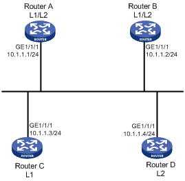
Configuration procedure
1. Configure an IP address for each interface. (Details not shown)
2. Enable IS-IS:
# Configure Router A.
<RouterA> system-view
[RouterA] isis 1
[RouterA-isis-1] network-entity 10.0000.0000.0001.00
[RouterA-isis-1] quit
[RouterA] interface GigabitEthernet 1/1/1
[RouterA-GigabitEthernet1/1/1] isis enable 1
[RouterA-GigabitEthernet1/1/1] quit
# Configure Router B.
<RouterB> system-view
[RouterB] isis 1
[RouterB-isis-1] network-entity 10.0000.0000.0002.00
[RouterB-isis-1] quit
[RouterB] interface GigabitEthernet 1/1/1
[RouterB-GigabitEthernet1/1/1] isis enable 1
[RouterB-GigabitEthernet1/1/1] quit
# Configure Router C.
<RouterC> system-view
[RouterC] isis 1
[RouterC-isis-1] network-entity 10.0000.0000.0003.00
[RouterC-isis-1] is-level level-1
[RouterC-isis-1] quit
[RouterC] interface GigabitEthernet 1/1/1
[RouterC-GigabitEthernet1/1/1] isis enable 1
[RouterC-GigabitEthernet1/1/1] quit
# Configure Router D.
<RouterD> system-view
[RouterD] isis 1
[RouterD-isis-1] network-entity 10.0000.0000.0004.00
[RouterD-isis-1] is-level level-2
[RouterD-isis-1] quit
[RouterD] interface GigabitEthernet 1/1/1
[RouterD-GigabitEthernet1/1/1] isis enable 1
[RouterD-GigabitEthernet1/1/1] quit
# Display information about IS-IS neighbors of Router A.
[RouterA] display isis peer
Peer information for ISIS(1)
----------------------------
System Id: 0000.0000.0002
Interface: GigabitEthernet1/1/1 Circuit Id: 0000.0000.0003.01
State: Up HoldTime: 21s Type: L1(L1L2) PRI: 64
System Id: 0000.0000.0003
Interface: GigabitEthernet1/1/1 Circuit Id: 0000.0000.0003.01
State: Up HoldTime: 6s Type: L1 PRI: 64
System Id: 0000.0000.0002
Interface: GigabitEthernet1/1/1 Circuit Id: 0000.0000.0004.01
State: Up HoldTime: 23s Type: L2(L1L2) PRI: 64
System Id: 0000.0000.0004
Interface: GigabitEthernet1/1/1 Circuit Id: 0000.0000.0004.01
State: Up HoldTime: 23s Type: L2 PRI: 64
# Display information about IS-IS interfaces of Router A.
[RouterA] display isis interface
Interface information for ISIS(1)
---------------------------------
Interface: GigabitEthernet1/1/1
Id IPV4.State IPV6.State MTU Type DIS
001 Up Down 1497 L1/L2 No/No
# Display IS-IS interfaces of Router C.
[RouterC] display isis interface
Interface information for ISIS(1)
---------------------------------
Interface: GigabitEthernet1/1/1
Id IPV4.State IPV6.State MTU Type DIS
001 Up Down 1497 L1/L2 Yes/No
# Display information about IS-IS interfaces of Router D.
[RouterD] display isis interface
Interface information for ISIS(1)
---------------------------------
Interface: GigabitEthernet1/1/1
Id IPV4.State IPV6.State MTU Type DIS
001 Up Down 1497 L1/L2 No/Yes
By using the default DIS priority, Router C is the Level-1 DIS, and Router D is the Level-2 DIS. The pseudonodes of Level-1 and Level-2 are 0000.0000.0003.01 and 0000.0000.0004.01 respectively.
3. Configure the DIS priority of Router A:
[RouterA] interface GigabitEthernet 1/1/1
[RouterA-GigabitEthernet1/1/1] isis dis-priority 100
# Display information about IS-IS neighbors of Router A.
[RouterA] display isis peer
Peer information for ISIS(1)
----------------------------
System Id: 0000.0000.0002
Interface: GigabitEthernet1/1/1 Circuit Id: 0000.0000.0001.01
State: Up HoldTime: 29s Type: L1(L1L2) PRI: 64
System Id: 0000.0000.0003
Interface: GigabitEthernet1/1/1 Circuit Id: 0000.0000.0001.01
State: Up HoldTime: 22s Type: L1 PRI: 64
System Id: 0000.0000.0002
Interface: GigabitEthernet1/1/1 Circuit Id: 0000.0000.0001.01
State: Up HoldTime: 22s Type: L2(L1L2) PRI: 64
System Id: 0000.0000.0004
Interface: GigabitEthernet1/1/1 Circuit Id: 0000.0000.0001.01
State: Up HoldTime: 22s Type: L2 PRI: 64
# Display information about IS-IS interfaces of Router A.
[RouterA] display isis interface
Interface information for ISIS(1)
---------------------------------
Interface: GigabitEthernet1/1/1
Id IPV4.State IPV6.State MTU Type DIS
001 Up Down 1497 L1/L2 Yes/Yes
After the DIS priority configuration, you can see Router A is the DIS for Level-1-2, and the pseudonode is 0000.0000.0001.01.
# Display information about IS-IS neighbors and interfaces of Router C.
[RouterC] display isis peer
Peer information for ISIS(1)
----------------------------
System Id: 0000.0000.0001
Interface: GigabitEthernet1/1/1 Circuit Id: 0000.0000.0001.01
State: Up HoldTime: 7s Type: L1 PRI: 100
System Id: 0000.0000.0002
Interface: GigabitEthernet1/1/1 Circuit Id: 0000.0000.0001.01
State: Up HoldTime: 23s Type: L1 PRI: 64
[RouterC] display isis interface
Interface information for ISIS(1)
---------------------------------
Interface: GigabitEthernet1/1/1
Id IPV4.State IPV6.State MTU Type DIS
001 Up Down 1497 L1/L2 No/No
# Display information about IS-IS neighbors and interfaces of Router D.
[RouterD] display isis peer
Peer information for ISIS(1)
----------------------------
System Id: 0000.0000.0001
Interface: GigabitEthernet1/1/1 Circuit Id: 0000.0000.0001.01
State: Up HoldTime: 7s Type: L2 PRI: 100
System Id: 0000.0000.0002
Interface: GigabitEthernet1/1/1 Circuit Id: 0000.0000.0001.01
State: Up HoldTime: 26s Type: L2 PRI: 64
[RouterD] display isis interface
Interface information for ISIS(1)
---------------------------------
Interface: GigabitEthernet1/1/1
Id IPV4.State IPV6.State MTU Type DIS
001 Up Down 1497 L1/L2 No/No
Configuring IS-IS route redistribution
Network requirements
As shown in Figure 18, Router A, Router B, Router C and Router D reside in the same AS. They use IS-IS to interconnect. Router A and Router B are Level-1 routers, Router D is a Level-2 router, and Router C is a Level-1-2 router.
Redistribute RIP routes into IS-IS on Router D.
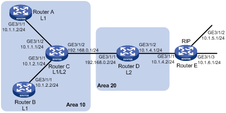
Configuration procedure
1. Configure IP addresses for interfaces. (Details not shown)
2. Configure IS-IS basic functions:
# Configure Router A.
<RouterA> system-view
[RouterA] isis 1
[RouterA-isis-1] is-level level-1
[RouterA-isis-1] network-entity 10.0000.0000.0001.00
[RouterA-isis-1] quit
[RouterA] interface GigabitEthernet 3/1/1
[RouterA-GigabitEthernet3/1/1] isis enable 1
[RouterA-GigabitEthernet3/1/1] quit
# Configure Router B.
<RouterB> system-view
[RouterB] isis 1
[RouterB-isis-1] is-level level-1
[RouterB-isis-1] network-entity 10.0000.0000.0002.00
[RouterB-isis-1] quit
[RouterB] interface GigabitEthernet 3/1/1
[RouterB-GigabitEthernet3/1/1] isis enable 1
[RouterB-GigabitEthernet3/1/1] quit
# Configure Router C.
<RouterC> system-view
[RouterC] isis 1
[RouterC-isis-1] network-entity 10.0000.0000.0003.00
[RouterC-isis-1] quit
[RouterC] interface GigabitEthernet 3/1/1
[RouterC-GigabitEthernet3/1/1] isis enable 1
[RouterC-GigabitEthernet3/1/1] quit
[RouterC] interface GigabitEthernet3/1/1
[RouterC-GigabitEthernet3/1/2] isis enable 1
[RouterC-GigabitEthernet3/1/2] quit
[RouterC] interface GigabitEthernet 3/1/3
[RouterC-GigabitEthernet3/1/3] isis enable 1
[RouterC-GigabitEthernet3/1/3] quit
# Configure Router D.
<RouterD> system-view
[RouterD] isis 1
[RouterD-isis-1] is-level level-2
[RouterD-isis-1] network-entity 20.0000.0000.0004.00
[RouterD-isis-1] quit
[RouterD] interface GigabitEthernet 3/1/1
[RouterD-GigabitEthernet3/1/1] isis enable 1
[RouterD-GigabitEthernet3/1/1] quit
# Display IS-IS routing information on each router.
[RouterA] display isis route
Route information for ISIS(1)
-----------------------------
ISIS(1) IPv4 Level-1 Forwarding Table
-------------------------------------
IPV4 Destination IntCost ExtCost ExitInterface NextHop Flags
--------------------------------------------------------------------------
10.1.1.0/24 10 NULL GE3/1/1 Direct D/L/-
10.1.2.0/24 20 NULL GE3/1/1 10.1.1.1 R/-/-
192.168.0.0/24 20 NULL GE3/1/1 10.1.1.1 R/-/-
0.0.0.0/0 10 NULL GE3/1/1 10.1.1.1 R/-/-
Flags: D-Direct, R-Added to RM, L-Advertised in LSPs, U-Up/Down Bit Set
[RouterC] display isis route
Route information for ISIS(1)
-----------------------------
ISIS(1) IPv4 Level-1 Forwarding Table
-------------------------------------
IPV4 Destination IntCost ExtCost ExitInterface NextHop Flags
--------------------------------------------------------------------------
10.1.1.0/24 10 NULL GE3/1/2 Direct D/L/-
10.1.2.0/24 10 NULL GE3/1/1 Direct D/L/-
192.168.0.0/24 10 NULL GE3/1/1 Direct D/L/-
Flags: D-Direct, R-Added to RM, L-Advertised in LSPs, U-Up/Down Bit Set
ISIS(1) IPv4 Level-2 Forwarding Table
-------------------------------------
IPV4 Destination IntCost ExtCost ExitInterface NextHop Flags
--------------------------------------------------------------------------
10.1.1.0/24 10 NULL GE3/1/2 Direct D/L/-
10.1.2.0/24 10 NULL GE3/1/1 Direct D/L/-
192.168.0.0/24 10 NULL GE3/1/3 Direct D/L/-
Flags: D-Direct, R-Added to RM, L-Advertised in LSPs, U-Up/Down Bit Set
[RouterD] display isis route
Route information for ISIS(1)
-----------------------------
ISIS(1) IPv4 Level-2 Forwarding Table
-------------------------------------
IPV4 Destination IntCost ExtCost ExitInterface NextHop Flags
--------------------------------------------------------------------------
192.168.0.0/24 10 NULL GE3/1/1 Direct D/L/-
10.1.1.0/24 20 NULL GE3/1/1 192.168.0.1 R/-/-
10.1.2.0/24 20 NULL GE3/1/1 192.168.0.1 R/-/-
Flags: D-Direct, R-Added to RM, L-Advertised in LSPs, U-Up/Down Bit Set
3. Configure RIPv2 on Router D and Router E, and configure route redistribution from RIP to IS-IS on Router D:
# Configure RIPv2 on Router D.
[RouterD] rip 1
[RouterD-rip-1] network 10.0.0.0
[RouterD-rip-1] version 2
[RouterD-rip-1] undo summary
# Configure RIPv2 on Router E.
[RouterE] rip 1
[RouterE-rip-1] network 10.0.0.0
[RouterE-rip-1] version 2
[RouterE-rip-1] undo summary
# Configure route redistribution from RIP to IS-IS on Router D.
[RouterD-rip-1] quit
[RouterD] isis 1
[RouterD–isis-1] import-route rip level-2
# Display IS-IS routing information on Router C.
[RouterC] display isis route
Route information for ISIS(1)
-----------------------------
ISIS(1) IPv4 Level-1 Forwarding Table
-------------------------------------
IPV4 Destination IntCost ExtCost ExitInterface NextHop Flags
--------------------------------------------------------------------------
10.1.1.0/24 10 NULL GE3/1/2 Direct D/L/-
10.1.2.0/24 10 NULL GE3/1/1 Direct D/L/-
192.168.0.0/24 10 NULL GE3/1/3 Direct D/L/-
Flags: D-Direct, R-Added to RM, L-Advertised in LSPs, U-Up/Down Bit Set
ISIS(1) IPv4 Level-2 Forwarding Table
-------------------------------------
IPV4 Destination IntCost ExtCost ExitInterface NextHop Flags
--------------------------------------------------------------------------
10.1.1.0/24 10 NULL GE3/1/2 Direct D/L/-
10.1.2.0/24 10 NULL GE3/1/1 Direct D/L/-
192.168.0.0/24 10 NULL GE3/1/3 Direct D/L/-
10.1.4.0/24 10 NULL GE3/1/3 192.168.0.2 R/L/-
10.1.5.0/24 20 NULL GE3/1/3 192.168.0.2 R/L/-
10.1.6.0/24 20 NULL GE3/1/3 192.168.0.2 R/L/-
Flags: D-Direct, R-Added to RM, L-Advertised in LSPs, U-Up/Down Bit Set
IS-IS GR configuration example
Network requirements
Router A, Router B, and Router C belong to the same IS-IS routing domain, as illustrated in Figure 19.
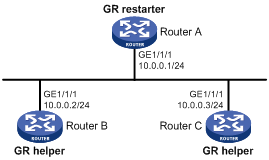
Configuration procedure
1. Configure IP addresses of the interfaces on each router and configure IS-IS:
Follow Figure 19 to configure the IP address and subnet mask of each interface on the router. (Details not shown)
Configure IS-IS on the routers, making sure that Router A, Router B and Router C can communicate with each other at Layer 3 and dynamic route update can be implemented among them with IS-IS. (Details not shown)
2. Configure IS-IS Graceful Restart:
# Enable IS-IS Graceful Restart on Router A and configure the Graceful Restart interval.
<RouterA> system-view
[RouterA] isis 1
[RouterA-isis-1] graceful-restart
[RouterA-isis-1] graceful-restart interval 150
[RouterA-isis-1] return
The configurations for Router B and Router C are similar and are not shown here.
3. Verify the configuration:
After Router A establishes adjacencies with Router B and Router C, they begin to exchange routing information. Restart IS-IS on Router A, which enters the restart state and sends connection requests to its neighbors through the Graceful Restart mechanism to synchronize the LSDB. Using the display isis graceful-restart status command can display the IS-IS GR status on Router A.
# Restart the IS-IS process on Router A.
<RouterA> reset isis all 1
Warning : Reset ISIS process? [Y/N]:y
# Check the IS-IS Graceful Restart state on Router A.
<RouterA> display isis graceful-restart status
Restart information for IS-IS(1)
--------------------------------------------------------------------
IS-IS(1) Level-1 Restart Status
Restart Interval: 150
SA Bit Supported
Total Number of Interfaces = 1
Restart Status: RESTARTING
Number of LSPs Awaited: 3
T3 Timer Status:
Remaining Time: 140
T2 Timer Status:
Remaining Time: 59
IS-IS(1) Level-2 Restart Status
Restart Interval: 150
SA Bit Supported
Total Number of Interfaces = 1
Restart Status: RESTARTING
Number of LSPs Awaited: 3
T3 Timer Status:
Remaining Time: 140
T2 Timer Status:
Remaining Time: 59
IS-IS FRR configuration example
Network requirements
Router S, Router A, and Router D belong to the same IS-IS routing domain as illustrated in Figure 20. Configure IS-IS FRR so that when the link between Router S and Router D fails, traffic can be switched to Link B immediately.
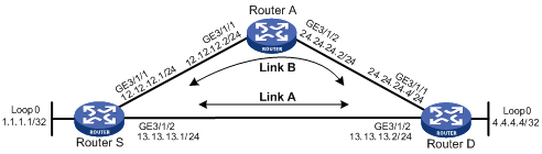
Configuration procedure
1. Configure IP addresses for the interfaces on each router and configure IS-IS:
Follow Figure 20 to configure the IP address and subnet mask of each interface on the routers. (Details not shown)
Configure IS-IS on the routers, ensuring that Router A, Router D, and Router S can communicate with each other at Layer 3. (Details not shown)
2. Configure IS-IS FRR:
You can enable IS-IS FRR to either automatically calculate a backup next hop, or to designate a backup next hop by using a routing policy.
¡ Method I
Enable IS-IS FRR to automatically calculate a backup next hop.
# Configure Router S.
<RouterS> system-view
[RouterS] bfd echo-source-ip 1.1.1.1
[RouterS] isis 1
[RouterS-isis-1] fast-reroute auto
[RouterS-isis-1] quit
# Configure Router D.
<RouterD> system-view
[RouterD] bfd echo-source-ip 4.4.4.4
[RouterD] isis 1
[RouterD-isis-1] fast-reroute auto
[RouterD-isis-1] quit
¡ Method II
Enable IS-IS FRR to designate a backup next hop by using a routing policy.
# Configure Router S.
<RouterS> system-view
[RouterS] bfd echo-source-ip 1.1.1.1
[RouterS] ip ip-prefix abc index 10 permit 4.4.4.4 32
[RouterS] route-policy frr permit node 10
[RouterS-route-policy] if-match ip-prefix abc
[RouterS-route-policy] apply fast-reroute backup-interface GigabitEthernet 3/1/1 backup-nexthop 12.12.12.2
[RouterS-route-policy] quit
[RouterS] isis 1
[RouterS-isis-1] fast-reroute route-policy frr
[RouterS-isis-1] quit
# Configure Router D.
<RouterD> system-view
[RouterD] bfd echo-source-ip 4.4.4.4
[RouterD] ip ip-prefix abc index 10 permit 1.1.1.1 32
[RouterD] route-policy frr permit node 10
[RouterD-route-policy] if-match ip-prefix abc
[RouterD-route-policy] apply fast-reroute backup-interface GigabitEthernet 3/1/1 backup-nexthop 24.24.24.2
[RouterD-route-policy] quit
[RouterD] isis 1
[RouterD-isis-1] fast-reroute route-policy frr
[RouterD-isis-1] quit
3. Verify the configuration:
# Display route 4.4.4.4/32 on Router S and you can view the backup next hop information.
[RouterS] display ip routing-table 4.4.4.4 verbose
Routing Table : Public
Summary Count : 1
Destination: 4.4.4.4/32
Protocol: ISIS Process ID: 1
Preference: 10 Cost: 10
NextHop: 13.13.13.2 Interface: GigabitEthernet3/1/2
BkNextHop: 12.12.12.2 BkInterface: GigabitEthernet3/1/1
RelyNextHop: 0.0.0.0 Neighbor : 0.0.0.0
Tunnel ID: 0x0 Label: NULL
State: Active Adv Age: 00h01m27s
Tag: 0
# Display route 1.1.1.1/32 on Router D. You can find the backup next hop information.
[RouterS] display ip routing-table 1.1.1.1 verbose
Routing Table : Public
Summary Count : 1
Destination: 1.1.1.1/32
Protocol: ISIS Process ID: 1
Preference: 10 Cost: 10
NextHop: 13.13.13.1 Interface: GigabitEthernet3/1/2
BkNextHop: 24.24.24.2 BkInterface: GigabitEthernet3/1/1
RelyNextHop: 0.0.0.0 Neighbor : 0.0.0.0
Tunnel ID: 0x0 Label: NULL
State: Active Adv Age: 00h01m27s
Tag: 0
IS-IS authentication configuration example
Network requirements
As shown in Figure 21, Router A, Router B, Router C and Router D reside in the same IS-IS routing domain.
Router A, Router B, and Router C belong to Area 10, and Router D belongs to Area 20.
Configure neighbor relationship authentication between neighbors. Configure area authentication in Area 10 to prevent untrusted routes from entering into the area. Configure routing domain authentication on Router C and Router D to prevent untrusted routes from entering the routing domain.
Figure 21 IS-IS authentication configuration
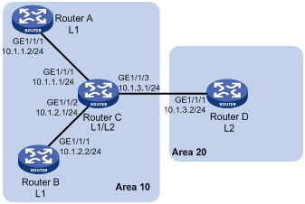
Configuration procedure
1. Configure IP addresses for interfaces. (Details not shown)
2. Configure IS-IS basic functions:
# Configure Router A.
<RouterA> system-view
[RouterA] isis 1
[RouterA-isis-1] network-entity 10.0000.0000.0001.00
[RouterA-isis-1] is-level level-1
[RouterA-isis-1] quit
[RouterA] interface GigabitEthernet 1/1/1
[RouterA-GigabitEthernet1/1/1] isis enable 1
[RouterA-GigabitEthernet1/1/1] quit
# Configure Router B.
<RouterB> system-view
[RouterB] isis 1
[RouterB-isis-1] network-entity 10.0000.0000.0002.00
[RouterA-isis-1] is-level level-1
[RouterB-isis-1] quit
[RouterB] interface GigabitEthernet 1/1/1
[RouterB-GigabitEthernet1/1/1] isis enable 1
[RouterB-GigabitEthernet1/1/1] quit
# Configure Router C.
<RouterC> system-view
[RouterC] isis 1
[RouterC-isis-1] network-entity 10.0000.0000.0003.00
[RouterC-isis-1] quit
[RouterC] interface GigabitEthernet 1/1/1
[RouterC-GigabitEthernet1/1/1] isis enable 1
[RouterC-GigabitEthernet1/1/1] quit
[RouterC] interface GigabitEthernet 1/1/2
[RouterC-GigabitEthernet1/1/2] isis enable 1
[RouterC-GigabitEthernet1/1/2] quit
[RouterC] interface GigabitEthernet 1/1/3
[RouterC-GigabitEthernet1/1/3] isis enable 1
[RouterC-GigabitEthernet1/1/3] quit
# Configure Router D.
<RouterD> system-view
[RouterD] isis 1
[RouterD-isis-1] network-entity 20.0000.0000.0001.00
[RouterD-isis-1] quit
[RouterD] interface GigabitEthernet 1/1/1
[RouterD-GigabitEthernet1/1/1] isis enable 1
[RouterD-GigabitEthernet1/1/1] quit
3. Configure neighbor relationship authentication between neighbors:
# Specify the MD5 authentication mode and password eRq on GigabitEthernet 1/1/1 of Router A and on GigabitEthernet 1/1/1 of Router C.
[RouterA] interface GigabitEthernet 1/1/1
[RouterA-GigabitEthernet1/1/1] isis authentication-mode md5 eRg
[RouterA-GigabitEthernet1/1/1] quit
[RouterC] interface GigabitEthernet 1/1/1
[RouterC-GigabitEthernet1/1/1] isis authentication-mode md5 eRg
[RouterC-GigabitEthernet1/1/1] quit
# Specify the MD5 authentication mode and password t5Hr on GigabitEthernet 1/1/1 of Router B and on GigabitEthernet 1/1/2 of Router C.
[RouterB] interface GigabitEthernet 1/1/1
[RouterB-GigabitEthernet1/1/1] isis authentication-mode md5 t5Hr
[RouterB-GigabitEthernet1/1/1] quit
[RouterC] interface GigabitEthernet 1/1/2
[RouterC-GigabitEthernet1/1/2] isis authentication-mode md5 t5Hr
[RouterC-GigabitEthernet1/1/2] quit
# Specify the MD5 authentication mode and password hSec on GigabitEthernet 1/1/3 of Router C and on GigabitEthernet 1/1/1 of Router D.
[RouterC] interface GigabitEthernet 1/1/3
[RouterC-GigabitEthernet1/1/3] isis authentication-mode md5 hSec
[RouterC-GigabitEthernet1/1/3] quit
[RouterD] interface GigabitEthernet 1/1/1
[RouterD-GigabitEthernet1/1/1] isis authentication-mode md5 hSec
[RouterD-GigabitEthernet1/1/1] quit
4. Configure area authentication. Specify the MD5 authentication mode and password 10Sec on Router A, Router B and Router C:
[RouterA] isis 1
[RouterA-isis-1] area-authentication-mode md5 10Sec
[RouterA-isis-1] quit
[RouterB] isis 1
[RouterB-isis-1] area-authentication-mode md5 10Sec
[RouterB-isis-1] quit
[RouterC] isis 1
[RouterC-isis-1] area-authentication-mode md5 10Sec
[RouterC-isis-1] quit
5. Configure routing domain authentication. Specify the MD5 authentication mode and password 1020Sec on Router C and Router D:
[RouterC] isis 1
[RouterC-isis-1] domain-authentication-mode md5 1020Sec
[RouterC-isis-1] quit
[RouterD] isis 1
[RouterD-isis-1] domain-authentication-mode md5 1020Sec
[RouterD-isis-1] isis 1
Configuring BFD for IS-IS
Network requirements
· As shown in Figure 22, IS-IS is enabled on Router A, Router B and Router C that are reachable to each other at the network layer.
· After the link over which Router A and Router B communicate through the Layer-2 switch fails, BFD can quickly detect the failure and notify IS-IS of the failure. Router A and Router B then communicate through Router C.
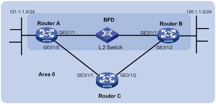
|
Device |
Interface |
IP address |
Device |
Interface |
IP address |
|
Router A |
GE3/1/1 |
192.168.0.102/24 |
Router B |
GE3/1/1 |
192.168.0.100/24 |
|
|
GE3/1/2 |
10.1.1.102/24 |
|
GE3/1/2 |
13.1.1.1/24 |
|
Router C |
GE3/1/1 |
10.1.1.100/24 |
|
|
|
|
|
GE3/1/2 |
13.1.1.2/24 |
|
|
|
Configuration procedure
1. Configure IP addresses for interfaces. (Details not shown)
2. Configure IS-IS basic functions:
# Configure Router A.
<RouterA> system-view
[RouterA] isis
[RouterA-isis-1] network-entity 10.0000.0000.0001.00
[RouterA-isis-1] quit
[RouterA] interface GigabitEthernet 3/1/1
[RouterA-GigabitEthernet3/1/1] isis enable
[RouterA-GigabitEthernet3/1/1] quit
[RouterA] interface GigabitEthernet 3/1/2
[RouterA-GigabitEthernet3/1/2] isis enable
[RouterA-GigabitEthernet3/1/2] quit
# Configure Router B.
<RouterB> system-view
[RouterB] isis
[RouterB-isis-1] network-entity 10.0000.0000.0002.00
[RouterB-isis-1] quit
[RouterB] interface GigabitEthernet 3/1/1
[RouterB-GigabitEthernet3/1/1] isis enable
[RouterB-GigabitEthernet3/1/1] quit
[RouterB] interface GigabitEthernet 3/1/2
[RouterB-GigabitEthernet3/1/2] isis enable
[RouterB-GigabitEthernet3/1/2] quit
# Configure Router C.
<RouterC> system-view
[RouterC] isis
[RouterC-isis-1] network-entity 10.0000.0000.0003.00
[RouterC-isis-1] quit
[RouterC] interface GigabitEthernet 3/1/1
[RouterC-GigabitEthernet3/1/1] isis enable
[RouterC-GigabitEthernet3/1/1] quit
[RouterC] interface GigabitEthernet 3/1/2
[RouterC-GigabitEthernet3/1/2] isis enable
[RouterC-GigabitEthernet3/1/2] quit
3. Configure BFD functions:
# Enable BFD on Router A and configure BFD parameters.
[RouterA] bfd session init-mode active
[RouterA] interface GigabitEthernet 3/1/1
[RouterA-GigabitEthernet3/1/1] isis bfd enable
[RouterA-GigabitEthernet3/1/1] bfd min-receive-interval 500
[RouterA-GigabitEthernet3/1/1] bfd min-transmit-interval 500
[RouterA-GigabitEthernet3/1/1] bfd detect-multiplier 7
# Enable BFD on Router B and configure BFD parameters.
[RouterB] bfd session init-mode active
[RouterB] interface GigabitEthernet 3/1/1
[RouterB-GigabitEthernet3/1/1] isis bfd enable
[RouterB-GigabitEthernet3/1/1] bfd min-receive-interval 500
[RouterB-GigabitEthernet3/1/1] bfd min-transmit-interval 500
[RouterB-GigabitEthernet3/1/1] bfd detect-multiplier 8
4. Verify the configuration:
The following configurations are performed on Router A. Configurations on Router B are similar. (Details not shown)
# Display the BFD information of Router A.
<RouterA> display bfd session
Total Session Num: 1 Init Mode: Active
Session Working Under Ctrl Mode:
LD/RD SourceAddr DestAddr State Holdtime Interface
3/1 192.168.0.102 192.168.0.100 Up 1700ms GE3/1/1
# Display route 120.1.1.0/24 on Router A, and you can see that Router A and Router B communicate through the Layer-2 switch.
<RouterA> display ip routing-table 120.1.1.0 verbose
Routing Table : Public
Summary Count : 2
Destination: 120.1.1.0/24
Protocol: ISIS Process ID: 0
Preference: 0 Cost: 2
NextHop: 192.168.0.100 Interface: GigabitEthernet3/1/1
BkNextHop: 0.0.0.0 BkInterface:
RelyNextHop: 0.0.0.0 Neighbor : 0.0.0.0
Tunnel ID: 0x0 Label: NULL
State: Active Adv Age: 00h58m10s
Tag: 0
Destination: 120.1.1.0/24
Protocol: ISIS Process ID: 1
Preference: 10 Cost: 4
NextHop: 10.1.1.100 Interface: GigabitEthernet3/1/2
BkNextHop: 0.0.0.0 BkInterface:
RelyNextHop: 0.0.0.0 Neighbor : 0.0.0.0
Tunnel ID: 0x0 Label: NULL
State: Invalid Adv Age: 00h58m05s
Tag: 0
# Enable debugging on Router A.
<RouterA> debugging isis bfd-event
<RouterA> terminal debugging
# When the link between Router B and the Layer-2 switch fails, BFD can quickly detect the failure.
#Aug 8 14:54:05:362 2008 RouterA IFNET/4/INTERFACE UPDOWN:
Trap 1.3.6.1.6.3.1.1.5.3<linkDown>: Interface 983041 is Down, ifAdminStatus is 1, ifOperStatus is 2
#Aug 8 14:54:05:363 2008 RouterA ISIS/4/ADJ_CHANGE:TrapID(1.3.6.1.2.1.138.0.17<isisAdjacencyChange>), ISIS Level-2 Adjencency IN Circuit-983041 State Change.
#Aug 8 14:54:05:364 2008 RouterA ISIS/4/ADJ_CHANGE:TrapID(1.3.6.1.2.1.138.0.17<isisAdjacencyChange>), ISIS Level-1 Adjencency IN Circuit-983041 State Change.
%Aug 8 14:54:05:365 2008 RouterA IFNET/4/LINK UPDOWN: GigabitEthernet3/1/1 link status is DOWN
%Aug 8 14:54:05:366 2008 RouterA IFNET/4/UPDOWN: Line protocol on the interface GigabitEthernet3/1/1 is DOWN
%Aug 8 14:54:05:367 2008 RouterA ISIS/4/ADJLOG:ISIS-1-ADJCHANGE: Adjacency To 0000.0000.0002 (GE3/1/1) DOWN, Level-2 Circuit Down.
%Aug 8 14:54:05:367 2008 RouterA ISIS/4/ADJLOG:ISIS-1-ADJCHANGE: Adjacency To 0000.0000.0002 (GE3/1/1) DOWN, Level-2 Adjacency clear.
%Aug 8 14:54:05:368 2008 RouterA ISIS/4/ADJLOG:ISIS-1-ADJCHANGE: Adjacency To 0000.0000.0002 (GE3/1/1) DOWN, Level-1 Circuit Down.
%Aug 8 14:54:05:369 2008 RouterA ISIS/4/ADJLOG:ISIS-1-ADJCHANGE: Adjacency To 0000.0000.0002 (GE3/1/1) DOWN, Level-1 Adjacency clear.
*Aug 8 14:54:05:370 2008 RouterA ISIS/6/ISIS:
ISIS-1-BFD: Success to send msg. Msg type 1 delete session. IfPhyIndex: 5 ,DstIPAddr: 192.168.0.100 , SrcIPAddr:192.168.0.102. NeighborType:Level-2.
*Aug 8 14:54:05:370 2008 RouterA ISIS/6/ISIS:
ISIS-1-BFD: Success to send msg. Msg type 1 delete session. IfPhyIndex: 5 ,DstIPAddr: 192.168.0.100 , SrcIPAddr:192.168.0.102. NeighborType:Level-1.
# Display the BFD information of Router A. Router A has removed its neighbor relationship with Router B and no information is output.
<RouterA> display bfd session
# Display route 120.1.1.0/24 on Router A, and you can see that Router A and Router B communicate through Router C.
<RouterA> display ip routing-table 120.1.1.0 verbose
Routing Table : Public
Summary Count : 2
Destination: 120.1.1.0/24
Protocol: ISIS Process ID: 1
Preference: 10 Cost: 4
NextHop: 10.1.1.100 Interface: GigabitEthernet3/1/2
BkNextHop: 0.0.0.0 BkInterface:
RelyNextHop: 0.0.0.0 Neighbor : 0.0.0.0
Tunnel ID: 0x0 Label: NULL
State: Active Adv Age: 00h58m10s
Tag: 0