- Table of Contents
-
- 06-Layer 3 - IP Routing Configuration Guide
- 00-Preface
- 01-IP Routing Basics
- 02-Static Routing Configuration
- 03-RIP Configuration
- 04-OSPF Configuration
- 05-IS-IS Configuration
- 06-BGP Configuration
- 07-Policy-Based Routing Configuration
- 08-IPv6 Static Routing Configuration
- 09-RIPng Configuration
- 10-OSPFv3 Configuration
- 11-IPv6 IS-IS Configuration
- 12-IPv6 BGP Configuration
- 13-IPv6 Policy-Based Routing Configuration
- 14-Routing Policy Configuration
- 15-QoS Policy Routing Configuration
- Related Documents
-
| Title | Size | Download |
|---|---|---|
| 09-RIPng Configuration | 238.34 KB |
Contents
RIPng packet processing procedure·
Configuring RIPng basic functions
Configuring RIPng route control
Configuring an additional routing metric
Configuring RIPng route summarization·
Configuring a RIPng route filtering policy
Configuring a priority for RIPng
Configuring RIPng route redistribution·
Tuning and optimizing the RIPng network
Configuring split horizon and poison reverse
Configuring zero field check on RIPng packets
Configuring the maximum number of equal cost routes for load balancing
Applying IPsec policies for RIPng
Displaying and maintaining RIPng
Configuring RIPng basic functions
Configuring RIPng route redistribution·
Configuring RIPng IPsec policies
Introduction to RIPng
RIP next generation (RIPng) is an extension of RIP-2 for IPv4. Most RIP concepts are applicable in RIPng.
RIPng for IPv6 has the following basic differences from RIP:
· UDP port number—RIPng uses UDP port 521 for sending and receiving routing information.
· Multicast address—RIPng uses FF02:9 as the link-local-router multicast address.
· Destination Prefix—128-bit destination address prefix.
· Next hop—128-bit IPv6 address.
· Source address—RIPng uses FE80::/10 as the link-local source address.
RIPng working mechanism
RIPng is a routing protocol based on the distance vector (D-V) algorithm. RIPng uses UDP packets to exchange routing information through port 521.
RIPng uses a hop count to measure the distance to a destination. The hop count is the metric or cost. The hop count from a router to a directly connected network is 0. The hop count between two directly connected routers is 1. When the hop count is greater than or equal to 16, the destination network or host is unreachable.
By default, the routing update is sent every 30 seconds. If the router receives no routing updates from a neighbor within 180 seconds, the routes learned from the neighbor are considered unreachable. If no routing update is received within another 240 seconds, the router removes these routes from the routing table.
RIPng supports split horizon and poison reverse to prevent routing loops and route redistribution.
Each RIPng router maintains a routing database, which includes route entries of all reachable destinations. A route entry contains the following information:
· Destination address—IPv6 address of a host or a network.
· Next hop address—IPv6 address of a neighbor along the path to the destination.
· Egress interface—Outbound interface that forwards IPv6 packets.
· Metric—Cost from the local router to the destination.
· Route time—Time that elapsed since a route entry is last changed. Each time a route entry is modified, the routing time is set to 0.
· Route tag—Identifies the route, used in a routing policy to control routing information. For more information about routing policy, see the chapter “Configuring routing policies.”
RIPng packet format
Basic format
A RIPng packet consists of a header and multiple route table entries (RTEs). The maximum number of RTEs in a packet depends on the IPv6 MTU of the sending interface.
Figure 1 RIPng basic packet format
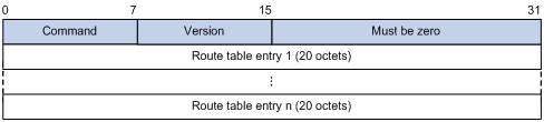
Packet header description:
· Command—Type of message. 0x01 indicates Request, 0x02 indicates Response.
· Version—Version of RIPng. It can only be 0x01 now.
· RTE—Route table entry, 20 bytes for each entry.
RTE format
The following are types of RTEs in RIPng:
· Next hop RTE—Defines the IPv6 address of a next hop.
· IPv6 prefix RTE—Describes the destination IPv6 address, route tag, prefix length and metric in the RIPng routing table.
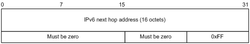
IPv6 next hop address is the IPv6 address of the next hop.
Figure 3 IPv6 prefix RTE format
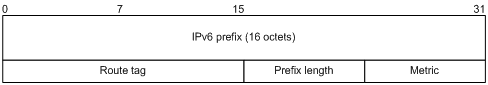
IPv6 prefix RTE format description:
· IPv6 prefix—Destination IPv6 address prefix
· Route tag—Route tag
· Prefix len—Length of the IPv6 address prefix
· Metric—Cost of a route
RIPng packet processing procedure
Request packet
When a RIPng router first starts or needs to update entries in its routing table, usually a multicast request packet is sent to ask for needed routes from neighbors.
The receiving RIPng router processes RTEs in the request. If only one RTE exists with the IPv6 prefix and prefix length both being 0, and with a metric value of 16, the RIPng router will respond with the entire routing table information in response messages. If multiple RTEs exist in the request message, the RIPng router will examine each RTE, update its metric, and send the requested routing information to the requesting router in the response packet.
Response packet
The response packet containing the local routing table information is generated as:
· A response to a request
· An update periodically
· A trigged update caused by route change
After receiving a response, a router checks the validity of the response before adding the route to its routing table, such as whether the source IPv6 address is the link-local address and whether the port number is correct. The response packet that failed the check will be discarded.
Protocols and standards
· RFC 2080, RIPng for IPv6
· RFC 2081, RIPng Protocol Applicability Statement
RIPng configuration task list
Complete the following tasks to configure RIPng:
|
Task |
Remarks |
|
|
Required |
||
|
Optional |
||
|
Optional |
||
|
Optional |
||
|
Optional |
||
|
Optional |
||
|
Optional |
||
|
Optional |
||
|
Optional |
||
|
Optional |
||
|
Configuring the maximum number of equal cost routes for load balancing |
Optional |
|
|
Optional |
||
Configuring RIPng basic functions
This section presents the information to configure the basic RIPng features.
You must enable RIPng first before configuring other tasks, but it is not necessary for RIPng related interface configurations, such as assigning an IPv6 address.
Configuration prerequisites
Before the configuration, complete the following tasks first:
· Enable IPv6.
· Configure IP addresses for interfaces, and make sure that all neighboring nodes are reachable to one another.
Configuration procedure
To configure the basic RIPng functions:
|
Command |
Remarks |
|
|
1. Enter system view. |
system-view |
N/A |
|
2. Create a RIPng process and enter RIPng view. |
ripng [ process-id ] [ vpn-instance vpn-instance-name ] |
Not created by default |
|
3. Return to system view. |
quit |
N/A |
|
4. Enter interface view. |
interface interface-type interface-number |
N/A |
|
5. Enable RIPng on the interface. |
ripng process-id enable |
Disabled by default |
|
|
NOTE: If RIPng is not enabled on an interface, the interface will not send or receive any RIPng route. |
Configuring RIPng route control
Before you configure RIPng, complete the following tasks:
· Configure IPv6 addresses for interfaces, and make sure that all neighboring nodes are reachable to one another.
· Configure RIPng basic functions
· Define an IPv6 ACL before using it for route filtering. See ACL and QoS Configuration Guide for related information.
· Define an IPv6 address prefix list before using it for route filtering. See the chapter “Configuring routing policies” for related information.
Configuring an additional routing metric
An additional routing metric can be added to the metric of an inbound or outbound RIP route.
The outbound additional metric is added to the metric of a sent route. The route’s metric in the routing table is not changed.
The inbound additional metric is added to the metric of a received route before the route is added into the routing table, so the route’s metric is changed.
To configure an inbound/outbound additional routing metric:
|
Command |
Remarks |
|
|
1. Enter system view. |
system-view |
N/A |
|
2. Enter interface view. |
interface interface-type interface-number |
N/A |
|
3. Specify an inbound routing additional metric. |
ripng metricin value |
Optional 0 by default |
|
4. Specify an outbound routing additional metric. |
ripng metricout value |
Optional 1 by default |
Configuring RIPng route summarization
To configure RIPng route summarization:
|
Step |
Command |
|
1. Enter system view. |
system-view |
|
2. Enter interface view. |
interface interface-type interface-number |
|
3. Advertise a summary IPv6 prefix. |
ripng summary-address ipv6-address prefix-length |
Advertising a default route
To advertise a default route:
|
Step |
Command |
Remarks |
|
1. Enter system view. |
system-view |
N/A |
|
2. Enter interface view. |
interface interface-type interface-number |
N/A |
|
3. Advertise a default route. |
ripng default-route { only | originate } [ cost cost ] |
Not advertised by default |
|
|
NOTE: With this feature enabled, a default route is advertised through the specified interface regardless of whether the default route is available in the local IPv6 routing table. |
Configuring a RIPng route filtering policy
You can reference a configured IPv6 ACL or prefix list to filter received/advertised routing information. You can also specify a routing protocol to filter outbound routes redistributed from the protocol.
To configure a RIPng route filtering policy:
|
Step |
Command |
Remarks |
|
1. Enter system view. |
system-view |
N/A |
|
2. Enter RIPng view. |
ripng [ process-id ] |
N/A |
|
3. Configure a filter policy to filter incoming routes. |
filter-policy { acl6-number | ipv6-prefix ipv6-prefix-name } import |
By default, RIPng does not filter incoming routing information. |
|
4. Configure a filter policy to filter outgoing routes. |
filter-policy { acl6-number | ipv6-prefix ipv6-prefix-name } export [ protocol [ process-id ] ] |
By default, RIPng does not filter outgoing routing information. |
Configuring a priority for RIPng
Any routing protocol has its own protocol priority used for optimal route selection. You can set a priority for RIPng manually. The smaller the value is, the higher the priority is.
To configure a RIPng priority:
|
Step |
Command |
Remarks |
|
1. Enter system view. |
system-view |
N/A |
|
2. Enter RIPng view. |
ripng [ process-id ] |
N/A |
|
3. Configure a RIPng priority. |
preference [ route-policy route-policy-name ] preference |
Optional. By default, the RIPng priority is 100. |
Configuring RIPng route redistribution
To configure RIPng route redistribution:
|
Step |
Command |
Remarks |
|
1. Enter system view. |
system-view |
N/A |
|
2. Enter RIPng view. |
ripng [ process-id ] |
N/A |
|
3. Configure a default routing metric for redistributed routes. |
default cost cost |
Optional. The default metric of redistributed routes is 0. |
|
4. Redistribute routes from another routing protocol. |
import-route protocol [ process-id ] [ allow-ibgp ] [ cost cost | route-policy route-policy-name ] * |
By default, no route redistribution is configured. |
Tuning and optimizing the RIPng network
This section describes how to tune and optimize the performance of the RIPng network as well as applications under special network environments. Before tuning and optimizing the RIPng network, complete the following tasks:
· Configure a network layer address for each interface.
· Configure the basic RIPng functions.
Configuring RIPng timers
You can adjust RIPng timers to optimize the performance of the RIPng network.
To configure RIPng timers:
|
Step |
Command |
Remarks |
|
1. Enter system view. |
system-view |
N/A |
|
2. Enter RIPng view. |
ripng [ process-id ] |
N/A |
|
3. Configure RIPng timers. |
timers { garbage-collect garbage-collect-value | suppress suppress-value | timeout timeout-value | update update-value } * |
Optional. The RIPng timers have the following defaults: · 30 seconds for the update timer · 180 seconds for the timeout timer · 120 seconds for the suppress timer · 120 seconds for the garbage-collect timer |
|
|
NOTE: When adjusting RIPng timers, consider the network performance and perform unified configurations on routers running RIPng to avoid unnecessary network traffic increase or route oscillation. |
Configuring split horizon and poison reverse
|
|
NOTE: If both split horizon and poison reverse are configured, only the poison reverse function takes effect. |
Configuring split horizon
The split horizon function disables a route learned from an interface from being advertised through the same interface to prevent routing loops between neighbors.
To configure split horizon:
|
Step |
Command |
Remarks |
|
1. Enter system view. |
system-view |
N/A |
|
2. Enter interface view. |
interface interface-type interface-number |
N/A |
|
3. Enable the split horizon function. |
ripng split-horizon |
Optional Enabled by default |
|
|
NOTE: H3C recommends enabling split horizon to prevent routing loops. |
Configuring the poison reverse function
The poison reverse function enables a route learned from an interface to be advertised through the interface. However, the metric of the route is set to 16, which causes the route to be unreachable.
To configure poison reverse:
|
Step |
Command |
Remarks |
|
1. Enter system view. |
system-view |
N/A |
|
2. Enter interface view. |
interface interface-type interface-number |
N/A |
|
3. Enable the poison reverse function. |
ripng poison-reverse |
Disabled by default |
Configuring zero field check on RIPng packets
Some fields in the RIPng packet must be zero, which are called “zero fields”. With zero field check on RIPng packets enabled, if such a field contains a non-zero value, the entire RIPng packet will be discarded. If you are sure that all packets are reliable, disable the zero field check to reduce the CPU processing time.
To configure RIPng zero field check:
|
Step |
Command |
Remarks |
|
1. Enter system view. |
system-view |
N/A |
|
2. Enter RIPng view. |
ripng [ process-id ] |
N/A |
|
3. Enable the zero field check. |
checkzero |
Optional Enabled by default |
Configuring the maximum number of equal cost routes for load balancing
To configure the maximum number of equal cost RIPng routes for load balancing:
|
Step |
Command |
Remarks |
|
1. Enter system view. |
system-view |
N/A |
|
2. Enter RIPng view. |
ripng [ process-id ] |
N/A |
|
3. Configure the maximum number of equal cost RIPng routes for load balancing. |
maximum load-balancing number |
Optional |
Applying IPsec policies for RIPng
To protect routing information and defend attacks, RIPng supports using an IPsec policy to authenticate protocol packets.
Outbound RIPng packets carry the Security Parameter Index (SPI) defined in the relevant IPsec policy. A router uses the SPI carried in a received packet to match against the configured IPsec policy. If they match, the router accepts the packet; otherwise, it discards the packet and will not establish a neighbor relationship with the sending router.
You can configure an IPsec policy for a RIPng process or interface. The IPsec policy configured for a process applies to all packets in the process. The IPsec policy configured on an interface applies to packets on the interface. If an interface and its process each have an IPsec policy configured, the interface uses its own IPsec policy.
Configuration prerequisites
Before you apply an IPsec policy for RIPng, complete following tasks:
· Create an IPsec proposal.
· Create an IPsec policy.
For more information about IPsec policy configuration, see Security Configuration Guide.
Configuration procedure
To apply an IPsec policy in a process:
|
Step |
Command |
Remarks |
|
1. Enter system view. |
system-view |
N/A |
|
2. Enter RIPng view. |
ripng [ process-id ] |
N/A |
|
3. Apply an IPsec policy in the process. |
enable ipsec-policy policy-name |
Not configured by default |
To apply an IPsec policy on an interface:
|
Step |
Command |
Remarks |
|
1. Enter system view. |
system-view |
N/A |
|
2. Enter interface view. |
interface interface-type interface-number |
N/A |
|
3. Apply an IPsec policy on the interface. |
ripng ipsec-policy policy-name |
Not configured by default |
|
|
NOTE: An IPsec policy used for RIPng can only be in manual mode. For more information, see Security Configuration Guide. |
Displaying and maintaining RIPng
|
Task |
Command |
Remarks |
|
Display configuration information of a RIPng process. |
display ripng [ process-id | vpn-instance vpn-instance-name ] [ | { begin | exclude | include } regular-expression ] |
Available in any view |
|
Display routes in the RIPng database. |
display ripng process-id database [ | { begin | exclude | include } regular-expression ] |
Available in any view |
|
Display the routing information of a specified RIPng process. |
display ripng process-id route [ | { begin | exclude | include } regular-expression ] |
Available in any view |
|
Display RIPng interface information. |
display ripng process-id interface [ interface-type interface-number ] [ | { begin | exclude | include } regular-expression ] |
Available in any view |
|
Reset a RIPng process. |
reset ripng process-id process |
Available in user view |
|
Clear statistics of a RIPng process. |
reset ripng process-id statistics |
Available in user view |
RIPng configuration examples
Configuring RIPng basic functions
Network requirements
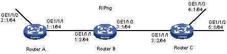
As shown in Figure 4, all routers learn IPv6 routing information through RIPng. Configure Router B to filter the route (3::/64) learned from Router C, which means the route will not be added to the routing table of Router B, and Router B will not forward it to Router A.
Configuration procedure
1. Configure the IPv6 address for each interface. (Details not shown)
2. Configure basic RIPng functions:
# Configure Router A.
<RouterA> system-view
[RouterA] ripng 1
[RouterA-ripng-1] quit
[RouterA] interface GigabitEthernet 1/1/1
[RouterA-GigabitEthernet1/1/1] ripng 1 enable
[RouterA-GigabitEthernet1/1/1] quit
[RouterA] interface GigabitEthernet 1/1/2
[RouterA-GigabitEthernet1/1/2] ripng 1 enable
[RouterA-GigabitEthernet1/1/2] quit
# Configure Router B.
<RouterB> system-view
[RouterB] ripng 1
[RouterB-ripng-1] quit
[RouterB] interface GigabitEthernet 1/1/1
[RouterB-GigabitEthernet1/1/1] ripng 1 enable
[RouterB-GigabitEthernet1/1/1] quit
[RouterB] interface GigabitEthernet 1/1/2
[RouterB-GigabitEthernet1/1/2] ripng 1 enable
[RouterB-GigabitEthernet1/1/2] quit
# Configure Router C.
<RouterC> system-view
[RouterC] ripng 1
[RouterC-ripng-1] quit
[RouterC] interface GigabitEthernet 1/1/1
[RouterC-GigabitEthernet1/1/1] ripng 1 enable
[RouterC-GigabitEthernet1/1/1] quit
[RouterC] interface GigabitEthernet 1/1/2
[RouterC-GigabitEthernet1/1/2] ripng 1 enable
[RouterC-GigabitEthernet1/1/2] quit
[RouterC] interface GigabitEthernet 1/1/3
[RouterC-GigabitEthernet1/1/3] ripng 1 enable
[RouterC-GigabitEthernet1/1/3] quit
# Display the routing table of Router B.
[RouterB] display ripng 1 route
Route Flags: A - Aging, S - Suppressed, G - Garbage-collect
----------------------------------------------------------------
Peer FE80::20F:E2FF:FE23:82F5 on GigabitEthernet1/1/1
Dest 1::/64,
via FE80::20F:E2FF:FE23:82F5, cost 1, tag 0, A, 6 Sec
Dest 2::/64,
via FE80::20F:E2FF:FE23:82F5, cost 1, tag 0, A, 6 Sec
Peer FE80::20F:E2FF:FE00:100 on GigabitEthernet1/1/2
Dest 3::/64,
via FE80::20F:E2FF:FE00:100, cost 1, tag 0, A, 11 Sec
Dest 4::/64,
via FE80::20F:E2FF:FE00:100, cost 1, tag 0, A, 11 Sec
Dest 5::/64,
via FE80::20F:E2FF:FE00:100, cost 1, tag 0, A, 11 Sec
3. Configure Router B to filter incoming and outgoing routes:
[RouterB] acl ipv6 number 2000
[RouterB-acl6-basic-2000] rule deny source 3::/64
[RouterB-acl6-basic-2000] rule permit
[RouterB-acl6-basic-2000] quit
[RouterB] ripng 1
[RouterB-ripng-1] filter-policy 2000 import
[RouterB-ripng-1] filter-policy 2000 export
# Display routing tables of Router B and Router A.
[RouterB] display ripng 1 route
Route Flags: A - Aging, S - Suppressed, G - Garbage-collect
----------------------------------------------------------------
Peer FE80::20F:E2FF:FE23:82F5 on GigabitEthernet1/1/1
Dest 1::/64,
via FE80::20F:E2FF:FE23:82F5, cost 1, tag 0, A, 2 Sec
Dest 2::/64,
via FE80::20F:E2FF:FE23:82F5, cost 1, tag 0, A, 2 Sec
Peer FE80::20F:E2FF:FE00:100 on GigabitEthernet1/1/2
Dest 4::/64,
via FE80::20F:E2FF:FE00:100, cost 1, tag 0, A, 5 Sec
Dest 5::/64,
via FE80::20F:E2FF:FE00:100, cost 1, tag 0, A, 5 Sec
[RouterA] display ripng 1 route
Route Flags: A - Aging, S - Suppressed, G - Garbage-collect
----------------------------------------------------------------
Peer FE80::20F:E2FF:FE00:1235 on GigabitEthernet2/1/1
Dest 1::/64,
via FE80::20F:E2FF:FE00:1235, cost 1, tag 0, A, 2 Sec
Dest 4::/64,
via FE80::20F:E2FF:FE00:1235, cost 2, tag 0, A, 2 Sec
Dest 5::/64,
via FE80::20F:E2FF:FE00:1235, cost 2, tag 0, A, 2 Sec
Configuring RIPng route redistribution
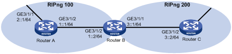
Network requirements
· Two RIPng processes are running on Router B, which communicates with Router A through RIPng 100 and with Router C through RIPng 200.
· Configure route redistribution on Router B, letting the two RIPng processes redistribute routes from each other. Set the default cost of redistributed routes from RIPng 200 to 3.
Configuration procedure
1. Configure IPv6 addresses for the interfaces. (Details not shown)
2. Configure RIPng basic functions:
# Enable RIPng 100 on Router A.
<RouterA> system-view
[RouterA] ripng 100
[RouterA-ripng-100] quit
[RouterA] interface GigabitEthernet 3/1/1
[RouterA-GigabitEthernet3/1/1] ripng 100 enable
[RouterA-GigabitEthernet3/1/1] quit
[RouterA] interface GigabitEthernet 3/1/2
[RouterA-GigabitEthernet3/1/2] ripng 100 enable
# Enable RIP 100 and RIP 200 on Router B.
<RouterB> system-view
[RouterB] ripng 100
[RouterB-ripng-100] quit
[RouterB] interface GigabitEthernet 3/1/2
[RouterB-GigabitEthernet3/1/2] ripng 100 enable
[RouterB-GigabitEthernet3/1/2] quit
[RouterB] ripng 200
[RouterB-ripng-200] quit
[RouterB] interface GigabitEthernet 3/1/1
[RouterB-GigabitEthernet3/1/1] ripng 200 enable
# Enable RIPng 200 on Router C.
<RouterC> system-view
[RouterC] ripng 200
[RouterC] interface GigabitEthernet 3/1/1
[RouterC-GigabitEthernet3/1/1] ripng 200 enable
[RouterC-GigabitEthernet3/1/1] quit
[RouterC] interface GigabitEthernet 3/1/2
[RouterC-GigabitEthernet3/1/2] ripng 200 enable
[RouterC-GigabitEthernet3/1/2] quit
# Display the routing table of Router A.
[RouterA] display ipv6 routing-table
Routing Table :
Destinations : 6 Routes : 6
Destination: ::1/128 Protocol : Direct
NextHop : ::1 Preference: 0
Interface : InLoop0 Cost : 0
Destination: 1::/64 Protocol : Direct
NextHop : 1::1 Preference: 0
Interface : GE3/1/2 Cost : 0
Destination: 1::1/128 Protocol : Direct
NextHop : ::1 Preference: 0
Interface : InLoop0 Cost : 0
Destination: 2::/64 Protocol : Direct
NextHop : 2::1 Preference: 0
Interface : GE3/1/1 Cost : 0
Destination: 2::1/128 Protocol : Direct
NextHop : ::1 Preference: 0
Interface : InLoop0 Cost : 0
Destination: FE80::/10 Protocol : Direct
NextHop : :: Preference: 0
Interface : NULL0 Cost : 0
3. Configure RIPng route redistribution:
# Configure route redistribution between the two RIPng processes on Router B.
[RouterB] ripng 100
[RouterB-ripng-100] default cost 3
[RouterB-ripng-100] import-route ripng 200
[RouterB-ripng-100] quit
[RouterB] ripng 200
[RouterB-ripng-200] import-route ripng 100
[RouterB-ripng-200] quit
# Display the routing table of Router A.
[RouterA] display ipv6 routing-table
Routing Table :
Destinations : 7 Routes : 7
Destination: ::1/128 Protocol : Direct
NextHop : ::1 Preference: 0
Interface : InLoop0 Cost : 0
Destination: 1::/64 Protocol : Direct
NextHop : 1::1 Preference: 0
Interface : GE3/1/2 Cost : 0
Destination: 1::1/128 Protocol : Direct
NextHop : ::1 Preference: 0
Interface : InLoop0 Cost : 0
Destination: 2::/64 Protocol : Direct
NextHop : 2::1 Preference: 0
Interface : GE3/1/1 Cost : 0
Destination: 2::1/128 Protocol : Direct
NextHop : ::1 Preference: 0
Interface : InLoop0 Cost : 0
Destination: 4::/64 Protocol : RIPng
NextHop : FE80::200:BFF:FE01:1C02 Preference: 100
Interface : GE3/1/2 Cost : 4
Destination: FE80::/10 Protocol : Direct
NextHop : :: Preference: 0
Interface : NULL0 Cost : 0
Configuring RIPng IPsec policies
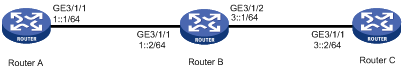
Network requirements
As shown in the following figure,
· Configure RIPng on the routers.
· Configure IPsec policies on the routers to authenticate and encrypt protocol packets.
Figure 6 Network diagram
Configuration procedure
1. Configure IPv6 addresses for interfaces. (Details not shown)
2. Configure RIPng basic functions:
# Configure Router A.
<RouterA> system-view
[RouterA] ripng 1
[RouterA-ripng-1] quit
[RouterA] interface GigabitEthernet 3/1/1
[RouterA-GigabitEthernet3/1/1] ripng 1 enable
[RouterA-GigabitEthernet3/1/1] quit
# Configure Router B.
<RouterB> system-view
[RouterB] ripng 1
[RouterB-ripng-1] quit
[RouterB] interface GigabitEthernet 3/1/1
[RouterB-GigabitEthernet3/1/1] ripng 1 enable
[RouterB-GigabitEthernet3/1/1] quit
[RouterB] interface GigabitEthernet 3/1/2
[RouterB-GigabitEthernet3/1/2] ripng 1 enable
[RouterB-GigabitEthernet3/1/2] quit
# Configure Router C.
<RouterC> system-view
[RouterC] ripng 1
[RouterC-ripng-1] quit
[RouterC] interface GigabitEthernet 3/1/1
[RouterC-GigabitEthernet3/1/1] ripng 1 enable
[RouterC-GigabitEthernet3/1/1] quit
3. Configure RIPng IPsec policies:
# On Router A, create an IPsec proposal named tran1, and set the encapsulation mode to transport mode, the security protocol to ESP, the encryption algorithm to DES, and authentication algorithm to SHA1; create an IPsec policy named policy001, specify the manual mode for it, reference IPsec proposal tran1, set the SPIs of the inbound and outbound SAs to 12345, and the keys for the inbound and outbound SAs using ESP to abcdefg.
[RouterA] ipsec proposal tran1
[RouterA-ipsec-proposal-tran1] encapsulation-mode transport
[RouterA-ipsec-proposal-tran1] transform esp
[RouterA-ipsec-proposal-tran1] esp encryption-algorithm des
[RouterA-ipsec-proposal-tran1] esp authentication-algorithm sha1
[RouterA-ipsec-proposal-tran1] quit
[RouterA] ipsec policy policy001 10 manual
[RouterA-ipsec-policy-manual-policy001-10] proposal tran1
[RouterA-ipsec-policy-manual-policy001-10] sa spi outbound esp 12345
[RouterA-ipsec-policy-manual-policy001-10] sa spi inbound esp 12345
[RouterA-ipsec-policy-manual-policy001-10] sa string-key outbound esp abcdefg
[RouterA-ipsec-policy-manual-policy001-10] sa string-key inbound esp abcdefg
[RouterA-ipsec-policy-manual-policy001-10] quit
# On Router B, create an IPsec proposal named tran1, and set the encapsulation mode to transport mode, the security protocol to ESP, the encryption algorithm to DES, and authentication algorithm to SHA1; create an IPsec policy named policy001, specify the manual mode for it, reference IPsec proposal tran1, set the SPIs of the inbound and outbound SAs to 12345, and the keys for the inbound and outbound SAs using ESP to abcdefg.
[RouterB] ipsec proposal tran1
[RouterB-ipsec-proposal-tran1] encapsulation-mode transport
[RouterB-ipsec-proposal-tran1] transform esp
[RouterB-ipsec-proposal-tran1] esp encryption-algorithm des
[RouterB-ipsec-proposal-tran1] esp authentication-algorithm sha1
[RouterB-ipsec-proposal-tran1] quit
[RouterB] ipsec policy policy001 10 manual
[RouterB-ipsec-policy-manual-policy001-10] proposal tran1
[RouterB-ipsec-policy-manual-policy001-10] sa spi outbound esp 12345
[RouterB-ipsec-policy-manual-policy001-10] sa spi inbound esp 12345
[RouterB-ipsec-policy-manual-policy001-10] sa string-key outbound esp abcdefg
[RouterB-ipsec-policy-manual-policy001-10] sa string-key inbound esp abcdefg
[RouterB-ipsec-policy-manual-policy001-10] quit
# On Router C, create an IPsec proposal named tran1, and set the encapsulation mode to transport mode, the security protocol to ESP, the encryption algorithm to DES, and authentication algorithm to SHA1; create an IPsec policy named policy001, specify the manual mode for it, reference IPsec proposal tran1, set the SPIs of the inbound and outbound SAs to 12345, and the keys for the inbound and outbound SAs using ESP to abcdefg.
[RouterC] ipsec proposal tran1
[RouterC-ipsec-proposal-tran1] encapsulation-mode transport
[RouterC-ipsec-proposal-tran1] transform esp
[RouterC-ipsec-proposal-tran1] esp encryption-algorithm des
[RouterC-ipsec-proposal-tran1] esp authentication-algorithm sha1
[RouterC-ipsec-proposal-tran1] quit
[RouterC] ipsec policy policy001 10 manual
[RouterC-ipsec-policy-manual-policy001-10] proposal tran1
[RouterC-ipsec-policy-manual-policy001-10] sa spi outbound esp 12345
[RouterC-ipsec-policy-manual-policy001-10] sa spi inbound esp 12345
[RouterC-ipsec-policy-manual-policy001-10] sa string-key outbound esp abcdefg
[RouterC-ipsec-policy-manual-policy001-10] sa string-key inbound esp abcdefg
[RouterC-ipsec-policy-manual-policy001-10] quit
4. Apply the IPsec policies in the RIPng process:
# Configure Router A.
[RouterA] ripng 1
[RouterA-ripng-1] enable ipsec-policy policy001
[RouterA-ripng-1] quit
# Configure Router B.
[RouterB] ripng 1
[RouterB-ripng-1] enable ipsec-policy policy001
[RouterB-ripng-1] quit
# Configure Router C.
[RouterC] ripng 1
[RouterC-ripng-1] enable ipsec-policy policy001
[RouterC-ripng-1] quit
5. Verify the configuration:
RIPng traffic between Routers A, B and C is protected by IPsec.