- Table of Contents
-
- 06-Layer 3 - IP Routing Configuration Guide
- 00-Preface
- 01-IP Routing Basics
- 02-Static Routing Configuration
- 03-RIP Configuration
- 04-OSPF Configuration
- 05-IS-IS Configuration
- 06-BGP Configuration
- 07-Policy-Based Routing Configuration
- 08-IPv6 Static Routing Configuration
- 09-RIPng Configuration
- 10-OSPFv3 Configuration
- 11-IPv6 IS-IS Configuration
- 12-IPv6 BGP Configuration
- 13-IPv6 Policy-Based Routing Configuration
- 14-Routing Policy Configuration
- 15-QoS Policy Routing Configuration
- Related Documents
-
| Title | Size | Download |
|---|---|---|
| 12-IPv6 BGP Configuration | 425.95 KB |
Contents
IPv6 BGP configuration task list
Configuring IPv6 BGP basic functions
Configuring a preferred value for routes from a peer/peer group
Specifying the source interface for establishing TCP connections
Allowing the establishment of a non-direct EBGP connection
Configuring a description for an IPv6 peer/peer group
Disabling session establishment to an IPv6 peer/peer group
Logging IPv6 peer/peer group state changes
Controlling route distribution and reception
Configuring IPv6 BGP route redistribution
Configuring IPv6 BGP route summarization
Advertising a default route to an IPv6 peer/peer group
Configuring outbound route filtering
Configuring inbound route filtering
Configuring IPv6 BGP and IGP route synchronization
Configuring IPv6 BGP route attributes
Configuring IPv6 BGP preference and default LOCAL_PREF and NEXT_HOP attributes
Configuring the AS_PATH attribute
Tuning and optimizing IPv6 BGP networks
Configuring IPv6 BGP soft reset
Enabling the IPv6 BGP ORF capability
Enabling 4-byte AS number suppression
Configuring the maximum number of load-balanced routes
Enabling MD5 authentication for TCP connections
Applying an IPsec policy to an IPv6 BGP peer or peer group
Configuring a large scale IPv6 BGP network
Configuring IPv6 BGP peer group
Configuring IPv6 BGP community
Configuring an IPv6 BGP route reflector
Configuring basic 6PE capabilities
Configuring optional 6PE capabilities
Displaying and maintaining IPv6 BGP
Resetting IPv6 BGP connections
IPv6 BGP configuration examples
IPv6 BGP route reflector configuration
IPv6 BGP IPsec policy configuration
Troubleshooting IPv6 BGP configuration
IPv6 BGP peer relationship not established
|
|
NOTE: · The term router in this document refers to both routers and Layer 3 switches. · This chapter describes only configuration for IPv6 BGP. For BGP related information, see the chapter “Configuring BGP.” |
IPv6 BGP overview
BGP-4 was designed to carry only IPv4 routing information, and other network layer protocols such as IPv6 are not supported.
To support multiple network layer protocols, IETF extended BGP-4 by introducing Multiprotocol BGP (MP-BGP), which is defined in RFC 2858 (multiprotocol extensions for BGP-4).
MP-BGP for IPv6 is called “IPv6 BGP” for short.
IPv6 BGP puts IPv6 network layer information into the attributes of Network Layer Reachability Information (NLRI) and NEXT_HOP.
The NLRI attribute of IPv6 BGP involves:
· MP_REACH_NLRI—Multiprotocol Reachable NLRI, for advertising reachable route and next hop information.
· MP_UNREACH_NLRI—Multiprotocol Unreachable NLRI, for withdrawal of unreachable routes.
The NEXT_HOP attribute of IPv6 BGP is identified by an IPv6 unicast address or IPv6 local link address.
IPv6 BGP has the same messaging and routing mechanisms as BGP.
IPv6 BGP configuration task list
Complete the following tasks to configure IPv6 BGP:
|
Task |
Remarks |
|
|
Required |
||
|
Optional |
||
|
Configuring a preferred value for routes from a peer/peer group |
Optional |
|
|
Specifying the source interface for establishing TCP connections |
Optional |
|
|
Optional |
||
|
Optional |
||
|
Optional |
||
|
Optional |
||
|
Optional |
||
|
Optional |
||
|
Optional |
||
|
Optional |
||
|
Optional |
||
|
Optional |
||
|
Optional |
||
|
Configuring IPv6 BGP preference and default LOCAL_PREF and NEXT_HOP attributes |
Optional |
|
|
Optional |
||
|
Optional |
||
|
Optional |
||
|
Optional |
||
|
Optional |
||
|
Optional |
||
|
Optional |
||
|
Optional |
||
|
Optional |
||
|
Optional |
||
|
Optional |
||
|
Optional |
||
|
Optional |
||
|
Optional |
||
|
Optional |
||
Configuring IPv6 BGP basic functions
Configuration prerequisites
Before you configure IPv6 BGP basic functions, complete the following tasks:
· Specify IP addresses for interfaces.
· Enable IPv6 with the ipv6 command in system view.
|
|
NOTE: Create a peer group before you configure basic functions for it. For related information, see “Configuring IPv6 BGP peer group.” |
Specifying an IPv6 BGP peer
To configure an IPv6 BGP peer:
|
Step |
Command |
Remarks |
|
1. Enter system view. |
system-view |
N/A |
|
2. Enter BGP view. |
bgp as-number |
N/A |
|
3. Specify a router ID. |
router-id router-id |
Optional. Required if no IP addresses are configured for any interfaces. |
|
4. Enter IPv6 address family view. |
ipv6-family |
N/A |
|
5. Specify an IPv6 peer. |
peer ipv6-address as-number as-number |
N/A |
Injecting a local IPv6 route
To configure advertise a local route into the routing table:
|
Step |
Command |
Remarks |
|
1. Enter system view. |
system-view |
N/A |
|
2. Enter BGP view. |
bgp as-number |
N/A |
|
3. Enter IPv6 address family view. |
ipv6-family |
N/A |
|
4. Inject a local route into the IPv6 BGP routing table. |
network ipv6-address prefix-length [ short-cut | route-policy route-policy-name ] |
Not added by default |
Configuring a preferred value for routes from a peer/peer group
To configure a preferred value for routes received from a peer/peer group:
|
Step |
Command |
Remarks |
|
1. Enter system view. |
system-view |
N/A |
|
2. Enter BGP view. |
bgp as-number |
N/A |
|
3. Enter IPv6 address family view. |
ipv6-family |
N/A |
|
4. Configure a preferred value for routes received from an IPv6 peer/peer group. |
peer { ipv6-group-name | ipv6-address } preferred-value value |
By default, the preferred value is 0. |
|
|
NOTE: If you both reference a routing policy and use the command peer { ipv6-group-name | ipv6-address } preferred-value value to set a preferred value for routes from a peer/peer group, the routing policy sets the preferred value for routes matching it. If the preferred value in the routing policy is zero, the routes matching it will use the value set with the peer { ipv6-group-name | ipv6-address } preferred-value value command. For how to use a routing policy to set a preferred value, see the command peer { group-name | ipv4-address | ipv6-address } route-policy route-policy-name { import | export } in this document, and the command apply preferred-value preferred-value in the chapter “Routing policy configuration commands.” |
Specifying the source interface for establishing TCP connections
To specify the source interface for establishing TCP connections to a BGP peer or peer group:
|
Step |
Command |
Remarks |
|
1. Enter system view. |
system-view |
N/A |
|
2. Enter BGP view. |
bgp as-number |
N/A |
|
3. Enter IPv6 address family view. |
ipv6-family |
N/A |
|
4. Specify the source interface for establishing TCP connections to an IPv6 BGP peer or peer group. |
peer { ipv6-group-name | ipv6-address } connect-interface interface-type interface-number |
By default, IPv6 BGP uses the outbound interface of the best route to the IPv6 BGP peer or peer group as the source interface for establishing a TCP connection. |
|
|
NOTE: To establish a BGP connection, you must specify on the local router the source interface for establishing the TCP connection to the peer on the peering BGP router; otherwise, the local BGP router may fail to establish TCP connection to the peer when using the outbound interface of the best route as the source interface. |
Allowing the establishment of a non-direct EBGP connection
To allow the establishment of EBGP connection to a non-directly connected peer/peer group:
|
Step |
Command |
Remarks |
|
1. Enter system view. |
system-view |
N/A |
|
2. Enter BGP view. |
bgp as-number |
N/A |
|
3. Enter IPv6 address family view. |
ipv6-family |
N/A |
|
4. Allow the establishment of EBGP connection to a non directly connected peer/peer group. |
peer { ipv6-group-name | ipv6-address } ebgp-max-hop [ hop-count ] |
Not configured by default |
|
|
NOTE: In general, direct links should be available between EBGP peers. If not, you can use the peer ebgp-max-hop command to establish a multi-hop TCP connection in between. However, you need not use this command for direct EBGP connections with loopback interfaces. |
Configuring a description for an IPv6 peer/peer group
To configure description for an IPv6 peer/peer group:
|
Step |
Command |
Remarks |
|
1. Enter system view. |
system-view |
N/A |
|
2. Enter BGP view. |
bgp as-number |
N/A |
|
3. Enter IPv6 address family view. |
ipv6-family |
N/A |
|
4. Configure a description for an IPv6 peer/peer group. |
peer { ipv6-group-name | ipv6-address } description description-text |
Optional Not configured by default |
|
|
NOTE: The peer group to be configured with a description must have been created. |
Disabling session establishment to an IPv6 peer/peer group
To disable session establishment to a peer/peer group:
|
Step |
Command |
Remarks |
|
1. Enter system view. |
system-view |
N/A |
|
2. Enter BGP view. |
bgp as-number |
N/A |
|
3. Enter IPv6 address family view. |
ipv6-family |
N/A |
|
4. Disable session establishment to an IPv6 peer/peer group. |
peer { ipv6-group-name | ipv6-address } ignore |
Optional Not disabled by default |
Logging IPv6 peer/peer group state changes
To configure to log on the session and event information of an IPv6 peer/peer group:
|
Step |
Command |
Remarks |
|
1. Enter system view. |
system-view |
N/A |
|
2. Enter BGP view. |
bgp as-number |
N/A |
|
3. Enable logging of peer changes globally. |
log-peer-change |
Optional Enabled by default |
|
4. Enter IPv6 address family view. |
ipv6-family |
N/A |
|
5. Enable the state change logging for an IPv6 peer or peer group. |
peer { ipv6-group-name | ipv6-address } log-change |
Optional Enabled by default |
|
|
NOTE: For information about the log-peer-change command, see the chapter “BGP configuration commands.” |
Controlling route distribution and reception
The task includes routing information filtering, routing policy application and route dampening.
Configuration prerequisites
Before you configure route distribution and reception control, complete the following tasks
· Enable IPv6 with the ipv6 command in system view.
· Configure IPv6 BGP basic functions.
Configuring IPv6 BGP route redistribution
To configure IPv6 BGP route redistribution:
|
Step |
Command |
Remarks |
|
1. Enter system view. |
system-view |
N/A |
|
2. Enter BGP view. |
bgp as-number |
N/A |
|
3. Enter IPv6 address family view. |
ipv6-family |
N/A |
|
4. Enable default route redistribution into the IPv6 BGP routing table. |
default-route imported |
Optional Not enabled by default |
|
5. Enable route redistribution from another routing protocol. |
import-route protocol [ process-id [ med med-value | route-policy route-policy-name ] * ] |
Not enabled by default |
|
|
NOTE: If the default-route imported command is not configured, using the import-route command cannot redistribute any IGP default route. |
Configuring IPv6 BGP route summarization
To reduce the routing table size on medium and large BGP networks, configure route summarization on BGP routers. BGP supports only manual summarization of IPv6 routes.
To configure IPv6 BGP route summarization:
|
Step |
Command |
Remarks |
|
1. Enter system view. |
system-view |
N/A |
|
2. Enter BGP view. |
bgp as-number |
N/A |
|
3. Enter IPv6 address family view. |
ipv6-family |
N/A |
|
4. Configure manual route summarization. |
aggregate ipv6-address prefix-length [ as-set | attribute-policy route-policy-name | detail-suppressed | origin-policy route-policy-name | suppress-policy route-policy-name ] * |
Not configured by default |
Advertising a default route to an IPv6 peer/peer group
To advertise a default route to an IPv6 peer/peer group:
|
Step |
Command |
Remarks |
|
1. Enter system view. |
system-view |
N/A |
|
2. Enter BGP view. |
bgp as-number |
N/A |
|
3. Enter IPv6 address family view. |
ipv6-family |
N/A |
|
4. Advertise a default route to an IPv6 peer/peer group. |
peer { ipv6-group-name | ipv6-address } default-route-advertise [ route-policy route-policy-name ] |
Not advertised by default |
|
|
NOTE: With the peer default-route-advertise command executed, the local router advertises a default route with itself as the next hop to the specified IPv6 peer/peer group, regardless of whether the default route is available in the routing table. |
Configuring outbound route filtering
To configure outbound route filtering:
|
Step |
Command |
Remarks |
|
1. Enter system view. |
system-view |
N/A |
|
2. Enter BGP view. |
bgp as-number |
N/A |
|
3. Enter IPv6 address family view. |
ipv6-family |
N/A |
|
4. Configure the filtering of outgoing routes. |
filter-policy { acl6-number | ipv6-prefix ipv6-prefix-name } export [ protocol process-id ] |
Not configured by default |
|
5. Apply a routing policy to routes advertised to an IPv6 peer/peer group. |
peer { ipv6-group-name | ipv6-address } route-policy route-policy-name export |
Not applied by default |
|
6. Specify an IPv6 ACL to filter routes advertised to an IPv6 peer/peer group. |
peer { ipv6-group-name | ipv6-address } filter-policy acl6-number export |
Not specified by default |
|
7. Specify an AS path ACL to filter routes advertised to an IPv6 peer/peer group. |
peer { ipv6-group-name | ipv6-address } as-path-acl as-path-acl-number export |
Not specified by default |
|
8. Specify an IPv6 prefix list to filter routes advertised to an IPv6 peer/peer group. |
peer { ipv6-group-name | ipv6-address } ipv6-prefix ipv6-prefix-name export |
Not specified by default |
|
|
NOTE: · The members of a peer group and the peer group must be configured with the same route advertisement policy. · IPv6 BGP advertises routes passing the specified policy to peers. Using the protocol argument can filter only the routes redistributed from the specified protocol. If no protocol is specified, IPv6 BGP filters all routes to be advertised, including redistributed routes and routes imported with the network command. |
Configuring inbound route filtering
To configure inbound route filtering:
|
Step |
Command |
Remarks |
|
1. Enter system view. |
system-view |
N/A |
|
2. Enter BGP view. |
bgp as-number |
N/A |
|
3. Enter IPv6 address family view. |
ipv6-family |
N/A |
|
4. Configure inbound route filtering. |
filter-policy { acl6-number | ipv6-prefix ipv6-prefix-name } import |
Not configured by default |
|
5. Apply a routing policy to routes from an IPv6 peer/peer group. |
peer { ipv6-group-name | ipv6-address } route-policy route-policy-name import |
Not applied by default |
|
6. Specify an ACL to filter routes imported from an IPv6 peer/peer group. |
peer { ipv6-group-name | ipv6-address } filter-policy acl6-number import |
Not specified by default |
|
7. Specify an AS path ACL to filter routing information imported from an IPv6 peer/peer group. |
peer { ipv6-group-name | ipv6-address } as-path-acl as-path-acl-number import |
Not specified by default |
|
8. Specify an IPv6 prefix list to filter routing information imported from an IPv6 peer/peer group. |
peer { ipv6-group-name | ipv6-address } ipv6-prefix ipv6-prefix-name import |
Not specified by default |
|
9. Specify the upper limit of prefixes allowed to receive from an IPv6 peer/peer group. |
peer { ipv6-group-name | ipv6-address } route-limit limit [ percentage ] |
Optional Unlimited by default |
|
|
NOTE: · Only routes passing the configured filtering can be added into the local IPv6 BGP routing table. · Members of a peer group can have different inbound route filtering policies. |
Configuring IPv6 BGP and IGP route synchronization
By default, upon receiving an IBGP route, an IPv6 BGP router checks the route’s next hop. If the next hop is reachable, the IPv6 BGP router advertises the route to EBGP peers. If the synchronization feature is configured, in addition to the reachability check of the next hop, the IPv6 BGP router must find an active IGP route with the same network segment before it can advertise the route. (Use the display ipv6 routing-table protocol command to display the IGP route state.)
To configure IPv6 BGP and IGP route synchronization:
|
Step |
Command |
Remarks |
|
1. Enter system view. |
system-view |
N/A |
|
2. Enter BGP view. |
bgp as-number |
N/A |
|
3. Enter IPv6 address family view. |
ipv6-family |
N/A |
|
4. Enable route synchronization between IPv6 BGP and IGP. |
synchronization |
Not enabled by default |
Configuring route dampening
To configure BGP route dampening:
|
Step |
Command |
Remarks |
|
1. Enter system view. |
system-view |
N/A |
|
2. Enter BGP view. |
bgp as-number |
N/A |
|
3. Enter IPv6 address family view. |
ipv6-family |
N/A |
|
4. Configure IPv6 BGP route dampening parameters. |
dampening [ half-life-reachable half-life-unreachable reuse suppress ceiling | route-policy route-policy-name ]* |
Optional Not configured by default |
Configuring IPv6 BGP route attributes
This section describes how to use IPv6 BGP route attributes to modify BGP routing policy. These attributes are:
· IPv6 BGP protocol preference
· Default LOCAL_PREF attribute
· MED attribute
· NEXT_HOP attribute
· AS_PATH attribute
Configuration rerequisites
Before you configure IPv6 BGP route attributes, complete the following tasks:
· Enable IPv6 with the ipv6 command in system view.
· Configure IPv6 BGP basic functions.
Configuring IPv6 BGP preference and default LOCAL_PREF and NEXT_HOP attributes
To perform this configuration:
|
Step |
Command |
Remarks |
|
1. Enter system view. |
system-view |
N/A |
|
2. Enter BGP view. |
bgp as-number |
N/A |
|
3. Enter IPv6 address family view. |
ipv6-family |
N/A |
|
4. Configure preference values for IPv6 BGP external, internal, local routes. |
preference { external-preference internal-preference local-preference | route-policy route-policy-name } |
Optional. The default preference values of external, internal and local routes are 255, 255, 130 respectively. |
|
5. Configure the default local preference. |
default local-preference value |
Optional. The value defaults to 100. |
|
6. Advertise routes to an IPv6 peer/peer group with the local router as the next hop. |
peer { ipv6-group-name | ipv6-address } next-hop-local |
By default, IPv6 BGP specifies the local router as the next hop for routes sent to an IPv6 EBGP peer/peer group, but not for routes sent to an IPv6 IBGP peer/peer group. |
|
|
NOTE: · To make sure an IBGP peer can find the correct next hop, you can configure routes advertised to the IPv6 IBGP peer/peer group to use the local router as the next hop. If BGP load balancing is configured, the local router specifies itself as the next hop of routes sent to an IPv6 IBGP peer/peer group regardless of whether the peer next-hop-local command is configured. · In a “third party next hop” network where the two IPv6 EBGP peers reside in a common broadcast subnet, the router does not change the next hop for routes sent to the IPv6 EBGP peer/peer group by default, unless the peer next-hop-local command is configured. |
Configuring the MED attribute
To configure the MED attribute:
|
Step |
Command |
Remarks |
|
1. Enter system view. |
system-view |
N/A |
|
2. Enter BGP view. |
bgp as-number |
N/A |
|
3. Enter IPv6 address family view. |
ipv6-family |
N/A |
|
4. Configure a default MED value. |
default med med-value |
Optional 0 by default |
|
5. Enable the comparison of MED for routes from different EBGP peers. |
compare-different-as-med |
Optional Not enabled by default |
|
6. Enable the comparison of MED for routes from each AS. |
bestroute compare-med |
Optional Disabled by default |
|
7. Enable the comparison of MED for routes from confederation peers. |
bestroute med-confederation |
Optional Disabled by default |
Configuring the AS_PATH attribute
To configure the AS_PATH attribute:
|
Step |
Command |
Remarks |
|
1. Enter system view. |
system-view |
N/A |
|
2. Enter BGP view. |
bgp as-number |
N/A |
|
3. Enter IPv6 address family view. |
ipv6-family |
N/A |
|
4. Allow the local AS number to appear in AS_PATH of routes from a peer/peer group and specify the repeat times. |
peer { ipv6-group-name | ipv6-address } allow-as-loop [ number ] |
Optional. Not allowed by default. |
|
5. Specify a fake AS number for an IPv6 peer/peer group. |
peer { ipv6-group-name | ipv6-address } fake-as as-number |
Optional. Not specified by default. |
|
6. Disable IPv6 MBGP from considering the AS_PATH during best route selection. |
bestroute as-path-neglect |
Optional. Enabled by default. |
|
7. Configure to carry only the public AS number in updates sent to a peer/peer group. |
peer { ipv6-group-name | ipv6-address } public-as-only |
Optional. By default, IPv6 BGP updates carry private AS number. |
|
8. Substitute the local AS number for the AS number of an IPv6 peer/peer group identified in the AS_PATH attribute. |
peer { ipv6-group-name | ipv6-address } substitute-as |
Optional. Not substituted by default |
Tuning and optimizing IPv6 BGP networks
This section describes configurations of IPv6 BGP timers, IPv6 BGP connection soft reset and the maximum number of load balanced routes.
· IPv6 BGP timers
After establishing an IPv6 BGP connection, two routers send keepalive messages periodically to each other to maintain the connection. If a router receives no keepalive message from the peer after the holdtime elapses, it tears down the connection.
When establishing an IPv6 BGP connection, the two parties compare their holdtimes, taking the shorter one as the common holdtime. If the holdtime is 0, neither keepalive massage is sent, nor holdtime is checked.
· IPv6 BGP connection soft reset
After modifying a route selection policy, you have to reset IPv6 BGP connections to make the new one take effect. The current IPv6 BGP implementation supports the route-refresh feature that enables dynamic route refresh without needing to disconnect IPv6 BGP links.
After this feature is enabled on all IPv6 BGP routers, a router that wants to apply a new route selection policy advertises a route-refresh message to its peers, which then send their routing information to the router. After receiving the routing information, the router can perform dynamic route update by using the new policy without tearing down connections.
If a peer not supporting route-refresh exists in the network, configure the peer keep-all-routes command to save all routes from the peer. When the routing policy is changed, the system will update the IPv6 BGP routing table and apply the new policy.
Configuration prerequisites
Before you configure IPv6 BGP timers, complete the following tasks:
· Enable IPv6.
· Configure IPv6 BGP basic functions.
Configuring IPv6 BGP timers
To configure IPv6 BGP timers:
|
Step |
Command |
Remarks |
|
1. Enter system view. |
system-view |
N/A |
|
2. Enter BGP view. |
bgp as-number |
N/A |
|
3. Enter IPv6 address family view. |
ipv6-family |
N/A |
|
4. Configure IPv6 BGP timers. |
·
Specify keepalive interval and holdtime: ·
Configure keepalive interval and holdtime for
an IPv6 peer/peer group: |
Optional. The keepalive interval defaults to 60 seconds, holdtime defaults to 180 seconds. |
|
5. Configure the interval for sending the same update to an IPv6 peer/peer group. |
peer { ipv6-group-name | ipv6-address } route-update-interval interval |
Optional. The interval for sending the same update to an IBGP peer or an EBGP peer defaults to 15 seconds or 30 seconds. |
|
|
NOTE: · Timers configured using the timer command have lower priority than timers configured using the peer timer command. · The holdtime interval must be at least three times the keepalive interval. |
Configuring IPv6 BGP soft reset
Enabling route refresh
To enable route refresh:
|
Step |
Command |
Remarks |
|
1. Enter system view. |
system-view |
N/A |
|
2. Enter BGP view. |
bgp as-number |
N/A |
|
3. Enter IPv6 address family view. |
ipv6-family |
N/A |
|
4. Enable route refresh. |
peer { ipv6-group-name | ipv6-address } capability-advertise route-refresh |
Optional Enabled by default |
Performing manual soft-reset
To perform manual soft reset:
|
Step |
Command |
Remarks |
|
1. Enter system view. |
system-view |
N/A |
|
2. Enter BGP view. |
bgp as-number |
N/A |
|
3. Enter IPv6 address family view. |
ipv6-family |
N/A |
|
4. Save all routes from an IPv6 peer/peer group, not letting them go through the inbound policy. |
peer { ipv6-group-name | ipv6-address } keep-all-routes |
Optional Not saved by default |
|
5. Return to user viewN/A |
return |
N/A |
|
6. Soft-reset BGP connections manually. |
refresh bgp ipv6 { all | ipv6-address | group ipv6-group-name | external | internal } { export | import } |
N/A |
|
|
NOTE: If the peer keep-all-routes command is used, all routes from the peer/peer group will be saved regardless of whether the filtering policy is available. These routes will be used to generate IPv6 BGP routes after soft-reset is performed. |
Enabling the IPv6 BGP ORF capability
The BGP Outbound Route Filter (ORF) feature allows a BGP speaker to send its BGP peer a set of ORFs through route-refresh messages. The peer then applies the ORFs, in addition to its local routing policies (if any), to filter updates to the BGP speaker, reducing the number of exchanged update messages and saving network resources.
After you enable the BGP ORF capability, the local BGP router negotiates the ORF capability with the BGP peer through Open messages. The local BGP router determines whether to carry ORF information in messages. If yes, it will further determine whether to carry non-standard ORF information in the packets. After completing the negotiation process and establishing the neighboring relationship, the BGP router and its BGP peer can exchange ORF information through specific route-refresh messages.
For the parameters configured on both sides for ORF capability negotiation, see Table 1.
To enable the BGP ORF capability:
|
Step |
Command |
Remarks |
|
1. Enter system view. |
system-view |
N/A |
|
2. Enter BGP view. |
bgp as-number |
N/A |
|
3. Enter IPv6 address family view. |
ipv6-family |
N/A |
|
4. Enable BGP route refresh for a peer/peer group. |
peer { group-name | ipv6-address } capability-advertise route-refresh |
Enabled by default. |
|
5. Enable the non-standard ORF capability for a BGP peer/peer group. |
peer { group-name | ipv6-address } capability-advertise orf non-standard |
Optional. By default, standard BGP ORF capability defined in RFC 5291 and RFC 5292 is supported. |
|
6. Enable the ORF IP prefix negotiation capability for a BGP peer/peer group. |
peer { group-name | ip-address | ipv6-address } capability-advertise orf ip-prefix { both | receive | send } |
Not supported by default. |
Table 1 Description of the both, send, and receive parameters and the negotiation result
|
Local parameter |
Peer parameter |
Negotiation result |
|
send |
· receive · both |
The ORF sending capability is enabled locally and the ORF receiving capability is enabled on the peer. |
|
receive |
· send · both |
The ORF receiving capability is enabled locally and the ORF sending capability is enabled on the peer. |
|
both |
both |
Both the ORF sending and receiving capabilities are enabled locally and on the peer, respectively. |
Enabling 4-byte AS number suppression
The device supports 4-byte AS numbers and uses 4-byte AS numbers by default. If the peer devices support only 2-byte AS numbers, you must enable the 4-byte AS number suppression function on the device.
To enable 4-byte AS number suppression:
|
Step |
Command |
Remarks |
|
1. Enter system view. |
system-view |
N/A |
|
2. Enter BGP view. |
bgp as-number |
N/A |
|
3. Enter IPv6 address family view. |
ipv6-family |
N/A |
|
4. Enable 4-byte AS number suppression. |
peer { group-name | ip-address } capability-advertise suppress-4-byte-as |
Disabled by default |
|
|
NOTE: If the peer device supports 4-byte AS numbers, do not enable the 4-byte AS number suppression function; otherwise, the BGP peer relationship cannot be established. |
Configuring the maximum number of load-balanced routes
To configure the maximum number of load balanced routes:
|
Step |
Command |
Remarks |
|
1. Enter system view. |
system-view |
N/A |
|
2. Enter BGP view. |
bgp as-number |
N/A |
|
3. Enter IPv6 address family view. |
ipv6-family |
N/A |
|
4. Configure the maximum number of load balanced routes. |
balance number |
By default, no load balancing is enabled. |
Enabling MD5 authentication for TCP connections
IPv6 BGP employs TCP as the transport protocol. To enhance security, configure IPv6 BGP to perform MD5 authentication when establishing a TCP connection. If the authentication fails, no TCP connection can be established.
To enable MD5 authentication for TCP connections:
|
Step |
Command |
Remarks |
|
1. Enter system view. |
system-view |
N/A |
|
2. Enter BGP view. |
bgp as-number |
N/A |
|
3. Enter IPv6 address family view. |
ipv6-family |
N/A |
|
4. Enable MD5 authentication when establishing a TCP connection to the peer/peer group. |
peer { ipv6-group-name | ipv6-address } password { cipher | simple } password |
Not enabled by default |
|
|
NOTE: · The MD5 authentication for establishing TCP connections does not apply to BGP packets. · The MD5 authentication requires that the two parties have the same authentication mode and password to establish a TCP connection; otherwise, no TCP connection can be established due to authentication failure. |
Applying an IPsec policy to an IPv6 BGP peer or peer group
To protect routing information and defend attacks, IPv6 BGP can authenticate protocol packets by using an IPsec policy.
Outbound IPv6 BGP packets carry the Security Parameter Index (SPI) defined in the IPsec policy. A router uses the SPI carried in a received packet to match against the configured IPsec policy. If they match, the router accepts the packet; otherwise, it discards the packet and will not establish a neighbor relationship with the sending router.
Configuration prerequisites
Before you applye an IPsec policy to a peer/peer group, complete following tasks:
· Create an IPsec proposal.
· Create an IPsec policy.
For more information about IPsec policy configuration, see Security Configuration Guide.
Configuration procedure
To apply an IPsec policy to a peer/peer group
|
Step |
Command |
Remarks |
|
1. Enter system view. |
system-view |
N/A |
|
2. Enter BGP view. |
bgp as-number |
N/A |
|
3. Enter IPv6 address family view. |
ipv6-family |
N/A |
|
4. Apply an IPsec policy to a peer/peer group. |
peer { group-name | ip-address } ipsec-policy policy-name |
Not configured by default |
Configuring a large scale IPv6 BGP network
In a large-scale IPv6 BGP network, configuration and maintenance become no convenient due to too many peers. Configuring peer groups makes management easier and improves route distribution efficiency. Peer group includes IBGP peer group, where peers belong to the same AS, and EBGP peer group, where peers belong to different ASs. If peers in an EBGP group belong to the same external AS, the EBGP peer group is a pure EBGP peer group, and if not, a mixed EBGP peer group.
In a peer group, all members have a common policy. Using the community attribute can make a set of IPv6 BGP routers in multiple ASs have the same policy, because community sending between IPv6 BGP peers is not limited by AS.
To ensure connectivity between IBGP peers, make them fully meshed, but it becomes unpractical when too many IBGP peers exist. Using route reflectors or confederation can solve it. In a large-scale AS, both of them can be used.
Confederation configuration of IPv6 BGP is identical to that of BGP4, so it is not mentioned here.
Configuration prerequisites
Before you configure a large-scale IPv6 BGP network, complete the following tasks:
· Make peer nodes accessible to each other at the network layer.
· Enable BGP and configure a router ID.
Configuring IPv6 BGP peer group
Configuring an IBGP peer group
To configure an IBGP group:
|
Step |
Command |
Remarks |
|
1. Enter system view. |
system-view |
N/A |
|
2. Enter BGP view. |
bgp as-number |
N/A |
|
3. Enter IPv6 address family view. |
ipv6-family |
N/A |
|
4. Create an IBGP peer group. |
group ipv6-group-name [ internal ] |
N/A |
|
5. Add a peer into the group. |
peer ipv6-address group ipv6-group-name [ as-number as-number ] |
Not added by default |
Creating a pure EBGP peer group
To configure a pure EBGP group:
|
Step |
Command |
Remarks |
|
1. Enter system view. |
system-view |
N/A |
|
2. Enter BGP view. |
bgp as-number |
N/A |
|
3. Enter IPv6 address family view. |
ipv6-family |
N/A |
|
4. Create an EBGP peer group. |
group ipv6-group-name external |
N/A |
|
5. Configure the AS number for the peer group. |
peer ipv6-group-name as-number as-number |
Not configured by default |
|
6. Add an IPv6 peer into the peer group. |
peer ipv6-address group ipv6-group-name |
Not added by default |
|
|
NOTE: · To create a pure EBGP peer group, you must specify an AS number for the peer group. · If a peer was added into an EBGP peer group, you cannot specify any AS number for the peer group. |
Creating a mixed EBGP peer group
To create a mixed EBGP peer group:
|
Step |
Command |
Remarks |
|
1. Enter system view. |
system-view |
N/A |
|
2. Enter BGP view. |
bgp as-number |
N/A |
|
3. Enter IPv6 address family view. |
ipv6-family |
N/A |
|
4. Create an EBGP peer group. |
group ipv6-group-name external |
N/A |
|
5. Specify the AS number of an IPv6 peer. |
peer ipv6-address as-number as-number |
Not specified by default |
|
6. Add the IPv6 peer into the peer group. |
peer ipv6-address group ipv6-group-name |
Not added by default |
|
|
NOTE: When creating a mixed EBGP peer group, you must create a peer and specify its AS number that can be different from AS numbers of other peers; however, you cannot specify AS number for the EBGP peer group. |
Configuring IPv6 BGP community
Advertising community attribute to an IPv6 peer/peer group
To advertise community attribute to an IPv6 peer/peer group:
|
Command |
Remarks |
|
|
1. Enter system view. |
system-view |
N/A |
|
2. Enter BGP view. |
bgp as-number |
N/A |
|
3. Enter IPv6 address family view. |
ipv6-family |
N/A |
|
4. Advertise community attribute to an IPv6 peer/peer group. |
peer { ipv6-group-name | ipv6-address } advertise-community |
Not advertised by default |
|
5. Advertise extended community attribute to an IPv6 peer/peer group. |
peer { ipv6-group-name | ipv6-address } advertise-ext-community |
Not advertised by default |
Applying a routing policy to routes advertised to a peer/peer group
To apply a routing policy to routes advertised to a peer/peer group:
|
Step |
Command |
Remarks |
|
1. Enter system view. |
system-view |
N/A |
|
2. Enter BGP view. |
bgp as-number |
N/A |
|
3. Enter IPv6 address family view. |
ipv6-family |
N/A |
|
4. Apply a routing policy to routes advertised to an IPv6 peer/peer group. |
peer { ipv6-group-name | ipv6-address } route-policy route-policy-name export |
Not applied by default |
|
|
NOTE: · When you configure IPv6 BGP community, you must configure a routing policy to define the community attribute, and apply the routing policy to route advertisement. · For routing policy configuration, see the chapter “Configuring routing policies.” |
Configuring an IPv6 BGP route reflector
To configure an IPv6 BGP route reflector:
|
Command |
Remarks |
|
|
1. Enter system view. |
system-view |
N/A |
|
2. Enter BGP view. |
bgp as-number |
N/A |
|
3. Enter IPv6 address family view. |
ipv6-family |
N/A |
|
4. Configure the router as a route reflector and specify an IPv6 peer/peer group as a client. |
peer { ipv6-group-name | ipv6-address } reflect-client |
Not configured by default. |
|
5. Enable route reflection between clients. |
reflect between-clients |
Optional. Enabled by default. |
|
6. Configure the cluster ID of the route reflector. |
reflector cluster-id cluster-id |
Optional. By default, a route reflector uses its router ID as the cluster ID. |
|
|
NOTE: · In general, since the route reflector forwards routing information between clients, you are not required to make clients of a route reflector fully meshed. If clients are fully meshed, H3C recommends disabling route reflection between clients to reduce routing costs. · If a cluster has multiple route reflectors, you must specify the same cluster ID for these route reflectors to avoid routing loops. |
Configuring 6PE
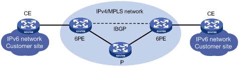
IPv6 provider edge (6PE) is a transition technology with which Internet service providers (ISPs) can use existing IPv4 backbone networks to provide access capability for sparsely populated IPv6 networks, allowing customer edge (CE) routers in these isolated IPv6 networks to communicate with IPv4 PE routers.
Work mechanism of 6PE:
IPv6 routing information from users is converted into IPv6 routing information with labels and then is flooded into IPv4 backbone networks of ISPs through BGP sessions. When IPv6 packets are forwarded, they will be labeled when entering tunnels of backbone networks. The tunnels can be MPLS LSPs.
IGPs running on ISP networks can be OSPF or IS-IS. Static routing, IGP, or EBGP can be used between CE and 6PE.
Figure 1 Network diagram for 6PE
|
|
NOTE: The P (Provider) router in the above figure refers to a backbone router in the network of a service provider. P is not directly connected with a CE and is required to have the basic MPLS capability. |
When an ISP wants to utilize the existing IPv4/MPLS network to provide IPv6 traffic switching capability, only the PE routers must be upgraded. Therefore, it is undoubtedly a high efficient solution. Furthermore, the operation risk of the 6PE technology is very low.
Configuration prerequisites
Before you configure 6PE, complete the following tasks:
· Configure the MPLS basic capability for the IPv4 MPLS backbone. For more information, see MPLS Configuration Guide.
· Configure the IPv6 BGP peer on the PE routers. For more information, see the chapter “Configuring BGP.”
· If a peer group is to be specified, create the peer group beforehand in BGP view.
|
|
NOTE: Because IPv6 packets have a length of 1280 bytes, you must configure the interface MTU and MPLS MTU for the PE router’s interface connecting to the IPv4 network to be larger than 1280 bytes and 1284 bytes, respectively. Otherwise, IPv6 packets are discarded. |
Configuring basic 6PE capabilities
To configure the 6PE basic capabilities:
|
Step |
Command |
Remarks |
|
1. Enter system view. |
system-view |
N/A |
|
2. Enter BGP view. |
bgp as-number |
N/A |
|
3. Specify the AS number for the 6PE peer or peer group. |
peer { ipv4-group-name | ipv4-address } as-number as-number |
Not specified by default |
|
4. Enter IPv6 address family view. |
ipv6-family |
N/A |
|
5. Enable the 6PE peer or peer group. |
peer { ipv4-group-name | ipv4-address | ipv6-address } enable |
Not enabled by default |
|
6. Enable the router to exchange labeled IPv6 routes with the 6PE peer or peer group. |
peer { ipv4-group-name | ipv4-address } label-route-capability |
Not enabled by default |
Configuring optional 6PE capabilities
To configure the 6PE optional capabilities:
|
Step |
Command |
Remarks |
|
1. Enter system view. |
system-view |
N/A |
|
2. Enter BGP view. |
bgp as-number |
N/A |
|
3. Specify the AS number for the 6PE peer or peer group. |
peer { ipv4-group-name | ipv4-address } as-number as-number |
Not specified by default |
|
4. Enter IPv6 address family view. |
ipv6-family |
N/A |
|
5. Enable the 6PE peer or peer group. |
peer { ipv4-group-name | ipv4-address | ipv6-address } enable |
Not enabled by default |
|
6. Advertise community attribute to the 6PE peer or peer group. |
peer { group-name | ipv4-address } advertise-community |
Optional Not advertised by default |
|
7. Advertise extended community attribute to the 6PE peer or peer group. |
peer { group-name | ipv4-address } advertise-ext-community |
Optional Not advertised by default |
|
8. Allow the local AS number to appear in routes from the peer or peer group and specify the repeat times. |
peer { group-name | ipv4-address } allow-as-loop [ number ] |
Optional Not allowed by default |
|
9. Specify an AS path ACL to filter routes from or to the 6PE peer or peer group. |
peer { group-name | ipv4-address } as-path-acl as-path-acl-number { import | export } |
Optional Not configured by default. |
|
10. Advertise a default route to the 6PE peer or peer group. |
peer { group-name | ipv4-address } default-route-advertise [ route-policy route-policy-name ] |
Optional Not advertised by default. |
|
11. Configure an inbound or outbound IPv6 ACL based filtering policy for the 6PE peer or peer group. |
peer { group-name | ipv4-address } filter-policy acl6-number { import | export } |
Optional Not configured by default. |
|
12. Add an 6PE peer to an existing peer group. |
peer ipv4-address group group-name [ as-number as-number ] |
Optional Not added by default |
|
13. Configure an inbound or outbound IPv6 prefix list based filtering policy for the 6PE peer or peer group. |
peer { group-name | ipv4-address } ipv6-prefix ipv6-prefix-name { import | export } |
Optional Not configured by default. |
|
14. Keep all routes from the 6PE peer or peer group, including routes not passing the inbound filtering policy. |
peer { group-name | ipv4-address } keep-all-routes |
Optional Not kept by default |
|
15. Configure the router as a route reflector and the 6PE peer or peer group as a client. |
peer { group-name | ipv4-address } reflect-client |
Optional Not configured by default. |
|
16. Configure an upper limit of IPv6 address prefixes that can be received from the 6PE peer or peer group. |
peer { group-name | ipv4-address } route-limit limit [ percentage ] |
Optional No limitation by default |
|
17. Apply a routing policy to routes outgoing or incoming from the 6PE peer or peer group. |
peer { group-name | ipv4-address } route-policy route-policy-name { import | export } |
Optional Not applied by default. |
|
18. Display information about the 6PE peer or peer group. |
display bgp ipv6 peer [ group-name log-info | ipv4-address verbose ] [ | { begin | exclude | include } regular-expression ] |
Optional Available in any view |
|
19. Display routes from or to the 6PE peer or peer group. |
display bgp ipv6 routing-table peer ipv4-address { advertised-routes | received-routes } [ network-address prefix-length | statistic ] [ | { begin | exclude | include } regular-expression ] |
Optional Available in any view |
|
20. Perform soft reset on the inbound or outbound BGP 6PE connection. |
refresh bgp ipv6 ipv4-address { export | import } |
Optional Available in user view |
|
21. Reset a BGP 6PE connection. |
reset bgp ipv6 ipv4-address |
Optional Available in user view |
Configuring BFD for IPv6 BGP
IPv6 BGP maintains neighbor relationships based on the keepalive timer and holdtime timer, which are set in seconds. IPv6 BGP defines that the holdtime interval must be at least three times the keepalive interval. This mechanism makes the detection of a link failure rather slow and thus causes a large quantity of packets to be dropped especially when the failed link is a high-speed link. You can enable BFD to detect the link to a peer. BFD can quickly detect any link failure and thus reduce network convergence time.
To enable BFD for a BGP peer:
|
Step |
Command |
Remarks |
|
1. Enter system view. |
system-view |
N/A |
|
2. Enable BGP and enter BGP view. |
bgp as-number |
Not enabled by default |
|
3. Enter IPv6 address family view. |
ipv6-family |
N/A |
|
4. Enable BFD for the specified BGP peer. |
peer ipv6-address bfd |
Not enabled for any BGP peer by default |
Displaying and maintaining IPv6 BGP
Displaying BGP
Resetting IPv6 BGP connections
|
Task |
Command |
Remarks |
|
Perform soft reset on IPv6 BGP connections. |
refresh bgp ipv6 { ipv4-address | ipv6-address | all | external | group ipv6-group-name | internal } { export | import } |
Available in any view |
|
Reset IPv6 BGP connections. |
reset bgp ipv6 { as-number | ipv4-address | ipv6-address [ flap-info ] | all | external | group group-name | internal } |
Available in any view |
Clearing IPv6 BGP information
|
Task |
Command |
Remarks |
|
Clear dampened IPv6 BGP routing information and release suppressed routes. |
reset bgp ipv6 dampening [ ipv6-address prefix-length ] |
Available in user view |
|
Clear IPv6 BGP route flap information. |
reset bgp ipv6 flap-info [ ipv6-address/prefix-length | as-path-acl as-path-acl-number | regexp as-path-regexp ] |
Available in user view |
IPv6 BGP configuration examples
|
|
NOTE: Some examples for IPv6 BGP configuration are similar to those of BGP. For related information, see the chapter “Configuring BGP”. |
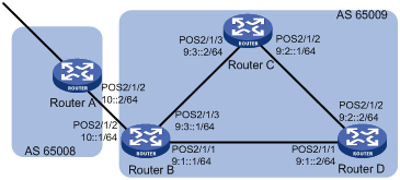
IPv6 BGP basic configuration
Network requirements
All routers in Figure 2 run IPv6 BGP. Between Router A and Router B is an EBGP connection. Router B, Router C, and Router D are fully meshed through IBGP connections.
Configuration procedure
1. Configure IPv6 addresses for interfaces. (Details not shown)
2. Configure IBGP connections:
# Configure Router B.
<RouterB> system-view
[RouterB] ipv6
[RouterB] bgp 65009
[RouterB-bgp] router-id 2.2.2.2
[RouterB-bgp] ipv6-family
[RouterB-bgp-af-ipv6] peer 9:1::2 as-number 65009
[RouterB-bgp-af-ipv6] peer 9:3::2 as-number 65009
[RouterB-bgp-af-ipv6] quit
[RouterB-bgp] quit
# Configure Router C.
<RouterC> system-view
[RouterC] ipv6
[RouterC] bgp 65009
[RouterC-bgp] router-id 3.3.3.3
[RouterC-bgp] ipv6-family
[RouterC-bgp-af-ipv6] peer 9:3::1 as-number 65009
[RouterC-bgp-af-ipv6] peer 9:2::2 as-number 65009
[RouterC-bgp-af-ipv6] quit
[RouterC-bgp] quit
# Configure Router D.
<RouterD> system-view
[RouterD] ipv6
[RouterD] bgp 65009
[RouterD-bgp] router-id 4.4.4.4
[RouterD-bgp] ipv6-family
[RouterD-bgp-af-ipv6] peer 9:1::1 as-number 65009
[RouterD-bgp-af-ipv6] peer 9:2::1 as-number 65009
[RouterD-bgp-af-ipv6] quit
[RouterD-bgp] quit
3. Configure the EBGP connection:
# Configure Router A.
<RouterA> system-view
[RouterA] ipv6
[RouterA] bgp 65008
[RouterA-bgp] router-id 1.1.1.1
[RouterA-bgp] ipv6-family
[RouterA-bgp-af-ipv6] peer 10::1 as-number 65009
[RouterA-bgp-af-ipv6] quit
[RouterA-bgp] quit
# Configure Router B.
[RouterB] bgp 65009
[RouterB-bgp] ipv6-family
[RouterB-bgp-af-ipv6] peer 10::2 as-number 65008
[RouterB-bgp-af-ipv6] quit
[RouterB-bgp] quit
# Display IPv6 peer information on Router B.
[RouterB] display bgp ipv6 peer
BGP local router ID : 2.2.2.2
Local AS number : 65009
Total number of peers : 3 Peers in established state : 3
Peer AS MsgRcvd MsgSent OutQ PrefRcv Up/Down State
10::2 65008 3 3 0 0 00:01:16 Established
9:3::2 65009 2 3 0 0 00:00:40 Established
9:1::2 65009 2 4 0 0 00:00:19 Established
# Display IPv6 peer information on Router C.
[RouterC] display bgp ipv6 peer
BGP local router ID : 3.3.3.3
Local AS number : 65009
Total number of peers : 2 Peers in established state : 2
Peer AS MsgRcvd MsgSent OutQ PrefRcv Up/Down State
9:3::1 65009 4 4 0 0 00:02:18 Established
9:2::2 65009 4 5 0 0 00:01:52 Established
Router A and B established an EBGP connection; Router B, C and D established IBGP connections with each other.
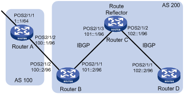
IPv6 BGP route reflector configuration
Network requirements
As shown in the following figure, Router B receives an EBGP update and sends it to Router C, which is configured as a route reflector with two clients: Router B and Router D.
Router B and Router D need not establish an IBGP connection because Router C reflects updates between them.
Figure 3 Network diagram
Configuration procedure
1. Configure IPv6 addresses for interfaces. (Details not shown)
2. Configure IPv6 BGP basic functions:
# Configure Router A.
<RouterA> system-view
[RouterA] ipv6
[RouterA] bgp 100
[RouterA-bgp] router-id 1.1.1.1
[RouterA-bgp] ipv6-family
[RouterA-bgp-af-ipv6] peer 100::2 as-number 200
[RouterA-bgp-af-ipv6] network 1:: 64
# Configure Router B
<RouterB> system-view
[RouterB] ipv6
[RouterB] bgp 200
[RouterB-bgp] router-id 2.2.2.2
[RouterB-bgp] ipv6-family
[RouterB-bgp-af-ipv6] peer 100::1 as-number 100
[RouterB-bgp-af-ipv6] peer 101::1 as-number 200
[RouterB-bgp-af-ipv6] peer 101::1 next-hop-local
# Configure Router C.
<RouterC> system-view
[RouterC] ipv6
[RouterC] bgp 200
[RouterC-bgp] router-id 3.3.3.3
[RouterC-bgp] ipv6-family
[RouterC-bgp-af-ipv6] peer 101::2 as-number 200
[RouterC-bgp-af-ipv6] peer 102::2 as-number 200
# Configure Router D.
<RouterD> system-view
[RouterD] ipv6
[RouterD] bgp 200
[RouterD-bgp] router-id 4.4.4.4
[RouterD-bgp] ipv6-family
[RouterD-bgp-af-ipv6] peer 102::1 as-number 200
3. Configure route reflector:
# Configure Router C as a route reflector, Router B and Router D as its clients.
[RouterC-bgp-af-ipv6] peer 101::2 reflect-client
[RouterC-bgp-af-ipv6] peer 102::2 reflect-client
4. Verify the configuration:
Use the display bgp ipv6 routing-table command on Router B and Router D respectively, you can find both of them have learned the network 1::/64.
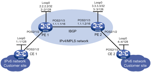
6PE configuration
Network requirements
As shown in the following figure:
· Routers PE 1 and PE 2 support 6PE;
· Routers CE 1 and CE 2 support IPv6;
· Between the PE routers is the IPv4/MPLS network of an ISP. The two PEs establish an IPv4 IBGP connection in between, and the IGP used is OSPF.
· The CEs reside in IPv6 networks. A CE and a PE use IPv6 link-local addresses to exchange routing information via a static route;
· Connect the two IPv6 networks through the IPv4/MPLS network with the 6PE feature.
Figure 4 Network diagram
Configuration procedure
1. Configure CE 1:
# Enable IPv6 packet forwarding.
<CE1> system-view
[CE1] ipv6
# Specify IP addresses for interfaces.
[CE1] interface Pos 2/1/2
[CE1-Pos2/1/2] ipv6 address auto link-local
[CE1-Pos2/1/2] quit
[CE1] interface loopback0
[CE1-LoopBack0] ipv6 address 1::1/128
[CE1-LoopBack0] quit
# Configure an IPv6 static route to PE 1.
[CE1] ipv6 route-static :: 0 Pos2/1/2
2. Configure PE 1:
# Enable IPv6 packet forwarding, MPLS and LDP.
<PE1> system-view
[PE1] ipv6
[PE1] mpls lsr-id 2.2.2.2
[PE1] mpls
[PE1-mpls] lsp-trigger all
[PE1-mpls] quit
[PE1] mpls ldp
[PE1-mpls-ldp] quit
# Configure an IPv6 link-local address for Pos2/1/2.
[PE1] interface Pos 2/1/2
[PE1-Pos2/1/2] ipv6 address auto link-local
[PE1-Pos2/1/2] quit
# Configure an IP address for Pos2/1/3 and enable MPLS and LDP.
[PE1] interface Pos 2/1/3
[PE1-Pos2/1/3] ip address 1.1.1.1 16
[PE1-Pos2/1/3] mpls
[PE1-Pos2/1/3] mpls ldp
[PE1-Pos2/1/3] quit
# Configure IP addresses for Loopback 0.
[PE1] interface loopback 0
[PE1-LoopBack0] ip address 2.2.2.2 32
[PE1-LoopBack0] ipv6 address 2::2/128
[PE1-LoopBack0] quit
# Configure IBGP, enable the peer’s 6PE capabilities, and redistribute IPv6 direct and static routes.
[PE1] bgp 65100
[PE1-bgp] peer 3.3.3.3 as-number 65100
[PE1-bgp] peer 3.3.3.3 connect-interface loopback 0
[PE1-bgp] ipv6-family
[PE1-bgp-af-ipv6] import-route direct
[PE1-bgp-af-ipv6] import-route static
[PE1-bgp-af-ipv6] peer 3.3.3.3 enable
[PE1-bgp-af-ipv6] peer 3.3.3.3 label-route-capability
[PE1-bgp-af-ipv6] quit
[PE1-bgp] quit
# Configure the static route to CE 1.
[PE1] ipv6 route-static 1::1 128 Pos2/1/2
# Configure OSPF for LSP establishment.
[PE1] ospf
[PE1-ospf-1] area 0
[PE1-ospf-1-area-0.0.0.0] network 2.2.2.2 0.0.0.0
[PE1-ospf-1-area-0.0.0.0] network 1.1.0.0 0.0.255.255
[PE1-ospf-1-area-0.0.0.0] quit
[PE1-ospf-1] quit
[PE1]
3. Configure PE 2:
<PE2> system-view
[PE2] ipv6
[PE2] mpls lsr-id 3.3.3.3
[PE2] mpls
[PE2-mpls] lsp-trigger all
[PE2-mpls] quit
[PE2] mpls ldp
[PE2-mpls-ldp] quit
[PE2] interface Pos 2/1/3
[PE2-Pos2/1/3] ip address 1.1.1.2 16
[PE2-Pos2/1/3] mpls
[PE2-Pos2/1/3] mpls ldp
[PE2-Pos2/1/3] quit
[PE2] interface Pos 2/1/2
[PE2-Pos2/1/2] ipv6 address auto link-local
[PE2-Pos2/1/2] quit
[PE2] interface loopback 0
[PE2-LoopBack0] ip address 3.3.3.3 32
[PE2-LoopBack0] ipv6 address 3::3/128
[PE2-LoopBack0] quit
# Configure IBGP, enable the peer’s 6PE capabilities, and redistribute IPv6 direct and static routes.
[PE2] bgp 65100
[PE2-bgp] peer 2.2.2.2 as-number 65100
[PE2-bgp] peer 2.2.2.2 connect-interface loopback 0
[PE2-bgp] ipv6-family
[PE2-bgp-af-ipv6] import-route direct
[PE2-bgp-af-ipv6] import-route static
[PE2-bgp-af-ipv6] peer 2.2.2.2 enable
[PE2-bgp-af-ipv6] peer 2.2.2.2 label-route-capability
[PE2-bgp-af-ipv6] quit
[PE2-bgp] quit
# Configure the static route to CE 2.
[PE1] ipv6 route-static 4::4 128 Pos2/1/2
# Configure OSPF for LSP establishment.
[PE1] ospf
[PE1-ospf-1] area 0
[PE1-ospf-1-area-0.0.0.0] network 3.3.3.3 0.0.0.0
[PE1-ospf-1-area-0.0.0.0] network 1.1.0.0 0.0.255.255
[PE1-ospf-1-area-0.0.0.0] quit
[PE1-ospf-1] quit
[PE1]
4. Configure CE 2:
# Enable IPv6 packet forwarding and specify IP addresses for interfaces.
<CE2> system-view
[CE2] ipv6
[CE2] interface Pos 2/1/2
[CE2-Pos2/1/2] ipv6 address auto link-local
[CE2-Pos2/1/2] quit
[CE2] interface loopback 0
[CE2-LoopBack0] ipv6 address 4::4/128
[CE2-LoopBack0] quit
# Configure the static route to PE 2.
[CE2] ipv6 route-static :: 0 Pos2/1/2
5. Verify the configuration:
# Display MPLS LSP information on PE 1.
<PE1> display mpls lsp
--------------------------------------------------------------
LSP Information: BGP IPV6 LSP
--------------------------------------------------------------
FEC : 1::1
In Label : 1024 Out Label : -----
In Interface : ----- OutInterface : -----
Vrf Name :
FEC : 2::2
In Label : 1025 Out Label : -----
In Interface : ----- OutInterface : -----
Vrf Name :
---------------------------------------------------------------
LSP Information: LDP LSP
---------------------------------------------------------------
FEC In/Out Label In/Out IF Vrf Name
3.3.3.3/32 NULL/3 -/S4/1/9:0
2.2.2.2/32 3/NULL S4/1/9:0/-
# Display the IPv6 BGP routing table on PE 1.
<PE1> display bgp ipv6 routing-table
Total Number of Routes: 4
BGP Local router ID is 2.2.2.2
Status codes: * - valid, ^ - VPNv4 best, > - best, d - damped,
h - history, i - internal, s - suppressed, S – Stale
Origin : i - IGP, e - EGP, ? - incomplete
*> Network : 1::1 PrefixLen : 128
NextHop : FE80::E142:0:4607:1 LocPrf :
PrefVal : 0 Label : NULL
MED : 0
Path/Ogn: ?
*> Network : 2::2 PrefixLen : 128
NextHop : ::1 LocPrf :
PrefVal : 0 Label : NULL
MED : 0
Path/Ogn: ?
*>i Network : 3::3 PrefixLen : 128
NextHop : ::FFFF:3.3.3.3 LocPrf : 100
PrefVal : 0 Label : NULL
MED : 0
Path/Ogn: ?
*>i Network : 4::4 PrefixLen : 128
NextHop : ::FFFF:3.3.3.3 LocPrf : 100
PrefVal : 0 Label : NULL
MED : 0
Path/Ogn: ?
After the above configuration, you can ping through the IPv6 address 4::4 of CE 2 from CE 1.
IPv6 BGP IPsec policy configuration
Network requirements
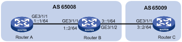
As shown in the following figure,
· Configure IPv6 BGP on the routers. Routers A and B establish an IBGP relationship. Routers B and C establish an EBGP relationship.
· Configure IPsec policies on the routers to authenticate and encrypt protocol packets.
Network Diagram
Figure 5 Network diagram
Configuration procedure
1. Configure IPv6 addresses for interfaces. (Details not shown)
2. Configure the IBGP connection:
# Configure Router A.
<RouterA> system-view
[RouterA] ipv6
[RouterA] bgp 65008
[RouterA-bgp] router-id 1.1.1.1
[RouterA-bgp] ipv6-family
[RouterA-bgp-af-ipv6] group ibgp internal
[RouterA-bgp-af-ipv6] peer 1::2 group ibgp
[RouterA-bgp-af-ipv6] quit
[RouterA-bgp] quit
# Configure Router B.
<RouterB> system-view
[RouterB] ipv6
[RouterB] bgp 65008
[RouterB-bgp] router-id 2.2.2.2
[RouterB-bgp] ipv6-family
[RouterB-bgp-af-ipv6] group ibgp internal
[RouterB-bgp-af-ipv6] peer 1::1 group ibgp
[RouterB-bgp-af-ipv6] quit
[RouterB-bgp] quit
3. Configure the EBGP connection:
# Configure Router C.
<RouterC> system-view
[RouterC] ipv6
[RouterC] bgp 65009
[RouterC-bgp] router-id 3.3.3.3
[RouterC-bgp] ipv6-family
[RouterC-bgp-af-ipv6] group ebgp external
[RouterC-bgp-af-ipv6] peer 3::1 as-number 65008
[RouterC-bgp-af-ipv6] peer 3::1 group ebgp
[RouterC-bgp-af-ipv6] quit
[RouterC-bgp] quit
# Configure Router B.
[RouterB-bgp] ipv6-family
[RouterB-bgp-af-ipv6] group ebgp external
[RouterB-bgp-af-ipv6] peer 3::2 as-number 65009
[RouterB-bgp-af-ipv6] peer 3::2 group ebgp
[RouterB-bgp-af-ipv6] quit
[RouterB-bgp] quit
4. Configure IPsec policies:
# On Router A, create an IPsec proposal named tran1, and set the encapsulation mode to transport mode, the security protocol to ESP, the encryption algorithm to DES, and authentication algorithm to SHA1; create an IPsec policy named policy001, specify the manual mode for it, reference IPsec proposal tran1, set the SPIs of the inbound and outbound SAs to 12345, and the keys for the inbound and outbound SAs using ESP to abcdefg.
[RouterA] ipsec proposal tran1
[RouterA-ipsec-proposal-tran1] encapsulation-mode transport
[RouterA-ipsec-proposal-tran1] transform esp
[RouterA-ipsec-proposal-tran1] esp encryption-algorithm des
[RouterA-ipsec-proposal-tran1] esp authentication-algorithm sha1
[RouterA-ipsec-proposal-tran1] quit
[RouterA] ipsec policy policy001 10 manual
[RouterA-ipsec-policy-manual-policy001-10] proposal tran1
[RouterA-ipsec-policy-manual-policy001-10] sa spi outbound esp 12345
[RouterA-ipsec-policy-manual-policy001-10] sa spi inbound esp 12345
[RouterA-ipsec-policy-manual-policy001-10] sa string-key outbound esp abcdefg
[RouterA-ipsec-policy-manual-policy001-10] sa string-key inbound esp abcdefg
[RouterA-ipsec-policy-manual-policy001-10] quit
# On Router B, create an IPsec proposal named tran1, and set the encapsulation mode to transport mode, the security protocol to ESP, the encryption algorithm to DES, and authentication algorithm to SHA1; create an IPsec policy named policy001, specify the manual mode for it, reference IPsec proposal tran1, set the SPIs of the inbound and outbound SAs to 12345, and the keys for the inbound and outbound SAs using ESP to abcdefg; create an IPsec proposal named tran2, and set the encapsulation mode to transport mode, the security protocol to ESP, the encryption algorithm to DES, and authentication algorithm to SHA1; create an IPsec policy named policy002, specify the manual mode for it, reference IPsec proposal tran2, set the SPIs of the inbound and outbound SAs to 54321, and the keys for the inbound and outbound SAs using ESP to gfedcba.
[RouterB] ipsec proposal tran1
[RouterB-ipsec-proposal-tran1] encapsulation-mode transport
[RouterB-ipsec-proposal-tran1] transform esp
[RouterB-ipsec-proposal-tran1] esp encryption-algorithm des
[RouterB-ipsec-proposal-tran1] esp authentication-algorithm sha1
[RouterB-ipsec-proposal-tran1] quit
[RouterB] ipsec policy policy001 10 manual
[RouterB-ipsec-policy-manual-policy001-10] proposal tran1
[RouterB-ipsec-policy-manual-policy001-10] sa spi outbound esp 12345
[RouterB-ipsec-policy-manual-policy001-10] sa spi inbound esp 12345
[RouterB-ipsec-policy-manual-policy001-10] sa string-key outbound esp abcdefg
[RouterB-ipsec-policy-manual-policy001-10] sa string-key inbound esp abcdefg
[RouterB-ipsec-policy-manual-policy001-10] quit
[RouterB] ipsec proposal tran2
[RouterB-ipsec-proposal-tran2] encapsulation-mode transport
[RouterB-ipsec-proposal-tran2] transform esp
[RouterB-ipsec-proposal-tran2] esp encryption-algorithm des
[RouterB-ipsec-proposal-tran2] esp authentication-algorithm sha1
[RouterB-ipsec-proposal-tran2] quit
[RouterB] ipsec policy policy002 10 manual
[RouterB-ipsec-policy-manual-policy002-10] proposal tran2
[RouterB-ipsec-policy-manual-policy002-10] sa spi outbound esp 54321
[RouterB-ipsec-policy-manual-policy002-10] sa spi inbound esp 54321
[RouterB-ipsec-policy-manual-policy002-10] sa string-key outbound esp gfedcba
[RouterB-ipsec-policy-manual-policy002-10] sa string-key inbound esp gfedcba
[RouterB-ipsec-policy-manual-policy002-10] quit
# On Router C, create an IPsec proposal named tran2, and set the encapsulation mode to transport mode, the security protocol to ESP, the encryption algorithm to DES, and authentication algorithm to SHA1; create an IPsec policy named policy002, specify the manual mode for it, reference IPsec proposal tran2, set the SPIs of the inbound and outbound SAs to 54321, and the keys for the inbound and outbound SAs using ESP to gfedcba.
[RouterC] ipsec proposal tran2
[RouterC-ipsec-proposal-tran2] encapsulation-mode transport
[RouterC-ipsec-proposal-tran2] transform esp
[RouterC-ipsec-proposal-tran2] esp encryption-algorithm des
[RouterC-ipsec-proposal-tran2] esp authentication-algorithm sha1
[RouterC-ipsec-proposal-tran2] quit
[RouterC] ipsec policy policy002 10 manual
[RouterC-ipsec-policy-manual-policy002-10] proposal tran2
[RouterC-ipsec-policy-manual-policy002-10] sa spi outbound esp 54321
[RouterC-ipsec-policy-manual-policy002-10] sa spi inbound esp 54321
[RouterC-ipsec-policy-manual-policy002-10] sa string-key outbound esp gfedcba
[RouterC-ipsec-policy-manual-policy002-10] sa string-key inbound esp gfedcba
[RouterC-ipsec-policy-manual-policy002-10] quit
5. Apply IPsec policies to IBGP peers:
# Configure Router A.
[RouterA] bgp 65008
[RouterA-bgp] ipv6-family
[RouterA-bgp-af-ipv6] peer 1::2 ipsec-policy policy001
[RouterA-bgp-af-ipv6] quit
[RouterA-bgp] quit
# Configure Router B.
[RouterB] bgp 65008
[RouterB-bgp] ipv6-family
[RouterB-bgp-af-ipv6] peer 1::1 ipsec-policy policy001
[RouterB-bgp-af-ipv6] quit
[RouterB-bgp] quit
6. Apply IPsec policies to EBGP peers:
# Configure Router C.
[RouterC] bgp 65009
[RouterC-bgp] ipv6-family
[RouterC-bgp-af-ipv6] peer ebgp ipsec-policy policy002
[RouterC-bgp-af-ipv6] quit
[RouterC-bgp] quit
# Configure Router B.
[RouterB] bgp 65008
[RouterB-bgp] ipv6-family
[RouterB-bgp-af-ipv6] peer ebgp ipsec-policy policy002
[RouterB-bgp-af-ipv6] quit
[RouterB-bgp] quit
7. Verify the configuration:
# Display detailed IPv6 BGP peer information.
[RouterB] display bgp ipv6 peer verbose
BGP Peer is 1::1, remote AS 65008,
Type: IBGP link
BGP version 4, remote router ID 1.1.1.1
BGP current state: Established, Up for 00h01m51s
BGP current event: RecvKeepalive
BGP last state: OpenConfirm
Port: Local – 1029 Remote - 179
Configured: Active Hold Time: 180 sec Keepalive Time: 60 sec
Received : Active Hold Time: 180 sec
Negotiated: Active Hold Time: 180 sec
Peer optional capabilities:
Peer support bgp multi-protocol extended
Peer support bgp route refresh capability
Address family IPv4 Unicast: advertised and received
Received: Total 0 messages, Update messages 0
Sent: Total 0 messages, Update messages 0
Maximum allowed prefix number: 4294967295
Threshold: 75%
Minimum time between advertisement runs is 30 seconds
Optional capabilities:
Route refresh capability has been enabled
ORF advertise capability based on prefix (type 64):
Local: both
Negotiated: send
Peer Preferred Value: 0
IPsec policy name: policy001, SPI :12345
Routing policy configured:
No routing policy is configured
BGP Peer is 3::2, remote AS 65009,
Type: EBGP link
BGP version 4, remote router ID 3.3.3.3
BGP current state: Established, Up for 00h01m51s
BGP current event: RecvKeepalive
BGP last state: OpenConfirm
Port: Local – 1029 Remote - 179
Configured: Active Hold Time: 180 sec Keepalive Time: 60 sec
Received : Active Hold Time: 180 sec
Negotiated: Active Hold Time: 180 sec
Peer optional capabilities:
Peer support bgp multi-protocol extended
Peer support bgp route refresh capability
Address family IPv4 Unicast: advertised and received
Received: Total 0 messages, Update messages 0
Sent: Total 0 messages, Update messages 0
Maximum allowed prefix number: 4294967295
Threshold: 75%
Minimum time between advertisement runs is 30 seconds
Optional capabilities:
Route refresh capability has been enabled
ORF advertise capability based on prefix (type 64):
Local: both
Negotiated: send
Peer Preferred Value: 0
IPsec policy name: policy002, SPI :54321
Routing policy configured:
No routing policy is configured
The output shows that both IBGP and EBGP neighbor relationships have been established, and all protocol packets are protected by IPsec.
Configuring BFD for IPv6 BGP
Network requirements
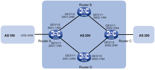
As shown in Figure 6,
· Configure OSPFv3 as the IGP in AS 200.
· Establish two IBGP connections between Router A and Router C. When both links are working, Router C adopts the link Router A<—>Router B<—>Router C to exchange packets with network 1200::0/64. Configure BFD over the link. Then if the link fails, BFD can quickly detect the failure and notify it to IPv6 BGP. Then the link Router A<—>Router D<—>Router C takes effect immediately.
Configuration procedure
1. Configure IP addresses for interfaces: (Details not shown)
2. Configure OSPFv3 to make sure that Router A and Router C are reachable to each other. (Details not shown)
3. Configure IPv6 BGP on Router A:
# Establish two IBGP connections between Router A and Router C.
<RouterA> system-view
[RouterA] bgp 200
[RouterA-bgp] ipv6-family
[RouterA-bgp-af-ipv6] peer 3002::2 as-number 200
[RouterA-bgp-af-ipv6] peer 2002::2 as-number 200
[RouterA-bgp-af-ipv6] quit
# When the two links between Router A and Router C are both up, Router C adopts the link Router A<—>Router B<—>Router C to exchange packets with network 1200::0/64. (Set a higher MED value for route 1200::0/64 sent to peer 2002::2 on Router A.)
¡ Create IPv6 ACL 2000 to permit 1200::0/64 to pass.
[RouterA] acl ipv6 number 2000
[RouterA-acl6-basic-2000] rule permit source 1200::0 64
[RouterA-acl6-basic-2000] quit
¡ Create two route policies, apply_med_50 and apply_med_100. Policy apply_med_50 sets the MED for route 1200::0/64 to 50. Policy apply_med_100 sets that to 100.
[RouterA] route-policy apply_med_50 permit node 10
[RouterA-route-policy] if-match ipv6 address acl 2000
[RouterA-route-policy] apply cost 50
[RouterA-route-policy] quit
[RouterA] route-policy apply_med_100 permit node 10
[RouterA-route-policy] if-match ipv6 address acl 2000
[RouterA-route-policy] apply cost 100
[RouterA-route-policy] quit
¡ Apply routing policy apply_med_50 to routes outgoing to peer 3002::2, and apply routing policy apply_med_100 to routes outgoing to peer 2002::2.
[RouterA] bgp 200
[RouterA-bgp] ipv6-family
[RouterA-bgp-af-ipv6] network 1200:: 64
[RouterA-bgp-af-ipv6] peer 3002::2 route-policy apply_med_50 export
[RouterA-bgp-af-ipv6] peer 2002::2 route-policy apply_med_100 export
# Configure BFD over the link to peer 3002::2 so that when the link Router A<—>Router B<—>Router C fails, BFD can quickly detect the failure and notify it to IPv6 BGP, and then the link Router A<—>Router D<—>Router C takes effect immediately.
[RouterA-bgp-af-ipv6] peer 3002::2 bfd
[RouterA-bgp-af-ipv6] quit
[RouterA-bgp] quit
4. Configure IPv6 BGP on Router C:
<RouterC> system-view
[RouterC] bgp 200
[RouterC-bgp] ipv6-family
[RouterC-bgp-af-ipv6] peer 3001::1 as-number 200
[RouterC-bgp-af-ipv6] peer 3001::1 bfd
[RouterC-bgp-af-ipv6] peer 2001::1 as-number 200
[RouterC-bgp-af-ipv6] quit
[RouterC-bgp] quit
5. Configure BFD parameters (you can use default BFD parameters instead):
# Configure Router A.
[RouterA] bfd session init-mode active
[RouterA] interface GigabitEthernet 3/1/2
¡ Configure the minimum interval for transmitting BFD control packets as 500 milliseconds.
[RouterA-GigabitEthernet3/1/2] bfd min-transmit-interval 500
¡ Configure the minimum interval for receiving BFD control packets as 500 milliseconds.
[RouterA-GigabitEthernet3/1/2] bfd min-receive-interval 500
¡ Configure the detect multiplier as 7.
[RouterA-GigabitEthernet3/1/2] bfd detect-multiplier 7
# Configure Router C.
[RouterC] bfd session init-mode active
[RouterC] interface GigabitEthernet 3/1/1
Configure the minimum interval for transmitting BFD control packets as 500 milliseconds.
[RouterC-GigabitEthernet3/1/1] bfd min-transmit-interval 500
Configure the minimum interval for receiving BFD control packets as 500 milliseconds.
[RouterC-GigabitEthernet3/1/1] bfd min-receive-interval 500
Configure the detect multiplier as 7.
[RouterC-GigabitEthernet3/1/1] bfd detect-multiplier 7
6. Verify the configuration:
The following operations are performed on Router C. Operations on Router A and Router B are similar. (Details not shown)
# Display detailed BFD session information.
<RouterC> display bfd session verbose
Total session number: 1 Up session number: 1 Init Mode: Active
IPv6 Session Working Under Ctrl Mode:
Local Discr: 17 Remote Discr: 13
Source IP: 3002::2
Destination IP: 3001::1
Session State: Up Interface: GigabitEthernet3/1/1
Min Trans Inter: 500ms Act Trans Inter: 500ms
Min Recv Inter: 500ms Act Detect Inter: 3500ms
Running Up for: 00:00:06 Auth mode: none
Connect Type: Indirect Board Num: 0
Protocol: BGP6
Diag Info: No Diagnostic
The output shows that a BFD session is established between Router A’s GigabitEthernet 3/1/2 and Router C’s GigabitEthernet 3/1/2 and that BFD runs properly.
# Display IPv6 peer information on Router C, and you can see that the neighborship between Router A and Router C is established.
<RouterC> display bgp ipv6 peer
BGP local router ID : 1.1.1.1
Local AS number : 200
Total number of peers : 2 Peers in established state : 2
Peer AS MsgRcvd MsgSent OutQ PrefRcv Up/Down State
2001::1 200 7 10 0 0 00:01:05 Established
3001::1 200 7 10 0 0 00:01:34 Established
# Display route 1200::0/64 on Router C, and you can see that Router A and Router C communicate through Router B.
<RouterC> display ipv6 routing-table 1200::0 64 verbose
Routing Table :
Summary Count : 2
Destination : 1200:: PrefixLength : 64
NextHop : 3001::1 Preference : 255
IpPrecedence : QosLcId :
RelayNextHop : FE80::3EE5:A6FF:FED1:A56E Tag : 0H
Neighbor : 3001::1 ProcessID : 0
Interface : GigabitEthernet3/1/1 Protocol : BGP4+
State : Active Adv GotQ Cost : 50
Tunnel ID : 0x0 Label : NULL
Age : 4538sec
Destination : 1200:: PrefixLength : 64
NextHop : 2001::1 Preference : 255
IpPrecedence : QosLcId :
RelayNextHop : FE80::223:89FF:FEEF:9A04 Tag : 0H
Neighbor : 2001::1 ProcessID : 0
Interface : GigabitEthernet3/1/2 Protocol : BGP4+
State : Inactive Adv GotQ Cost : 100
Tunnel ID : 0x0 Label : NULL
Age : 4515sec
The output shows that Router C has two routes to reach network 1200::0/64: Router C<—>Router B<—>Router A, which is the currently active route; Router C<—>Router D<—>Router A, which is the backup route.
# Enable BFD debugging on Router C.
<RouterC> debugging bfd scm
<RouterC> debugging bfd event
<RouterC> debugging bgp bfd
<RouterC> terminal monitor
<RouterC> terminal debugging
# The following debugging information shows that Router C can quickly detect the failure on Router B.
%Nov 5 11:42:24:172 2009 RouterC BFD/5/BFD_CHANGE_FSM: Sess[3002::2/3001::1,13/17,GE3/1/1,Ctrl], Sta: UP->DOWN, Diag: 1
%Nov 5 11:42:24:172 2009 RouterC BGP/5/BGP_STATE_CHANGED: 3001::1 state is changed from ESTABLISHED to IDLE.
*Nov 5 11:42:24:187 2009 RouterC RM/6/RMDEBUG: BGP_BFD: Recv BFD DOWN msg, Src IP 3002::2, Dst IP 3001::1, Instance ID 0.
*Nov 5 11:42:24:187 2009 RouterC RM/6/RMDEBUG: BGP_BFD: Reset BGP session 3001::1 for BFD session down.
*Nov 5 11:42:24:187 2009 RouterC RM/6/RMDEBUG: BGP_BFD: Send DELETE msg to BFD, Connection type DIRECT, Src IP 3002::2, Dst IP 3001::1, Instance ID 0.
# Display route 1200::0/64 on Router C, and you can see that Router A and Router C communicate through Router D.
<RouterC> display ipv6 routing-table 1200::0 64 verbose
Routing Table :
Summary Count : 1
Destination : 1200:: PrefixLength : 64
NextHop : 2001::1 Preference : 255
IpPrecedence : QosLcId :
RelayNextHop : FE80::223:89FF:FEEF:9A04 Tag : 0H
Neighbor : 2001::1 ProcessID : 0
Interface : GigabitEthernet3/1/2 Protocol : BGP4+
State : Active Adv GotQ Cost : 100
Tunnel ID : 0x0 Label : NULL
Age : 4635sec
The output shows that Router C has one route to reach network 1200::0/64, that is, Router C<—>Router D<—>Router A.
Troubleshooting IPv6 BGP configuration
IPv6 BGP peer relationship not established
Symptom
Display BGP peer information by using the display bgp ipv6 peer command. The state of the connection to the peer cannot become established.
Analysis
To become IPv6 BGP peers, any two routers must establish a TCP session using port 179 and exchange open messages successfully.
Solution
1. Use the display current-configuration command to check that the peer’s AS number is correct.
2. Use the display bgp ipv6 peer command to check that the peer’s IPv6 address is correct.
3. If a loopback interface is used, check that the loopback interface is specified with the peer connect-interface command.
4. If the peer is not directly connected, check that the peer ebgp-max-hop command is configured.
5. Check that a valid route to the peer is available.
6. Use the ping command to check the connectivity to the peer.
7. Use the display tcp ipv6 status command to check the TCP connection.
8. Check whether an ACL for disabling TCP port 179 is configured.