- Table of Contents
-
- 06-Layer 3 - IP Routing Configuration Guide
- 00-Preface
- 01-IP Routing Basics
- 02-Static Routing Configuration
- 03-RIP Configuration
- 04-OSPF Configuration
- 05-IS-IS Configuration
- 06-BGP Configuration
- 07-Policy-Based Routing Configuration
- 08-IPv6 Static Routing Configuration
- 09-RIPng Configuration
- 10-OSPFv3 Configuration
- 11-IPv6 IS-IS Configuration
- 12-IPv6 BGP Configuration
- 13-IPv6 Policy-Based Routing Configuration
- 14-Routing Policy Configuration
- 15-QoS Policy Routing Configuration
- Related Documents
-
| Title | Size | Download |
|---|---|---|
| 07-Policy-Based Routing Configuration | 142.13 KB |
Contents
Configuring policy-based routing
Introduction to policy-based routing
Displaying and maintaining PBR configuration
Configuring local PBR based on packet type
Configuring interface PBR based on packet type
Introduction to policy-based routing
What is policy-based routing
Policy-based routing (PBR) is a routing mechanism based on user-defined policies. Different from the traditional destination-based routing mechanism, PBR enables you to use a policy to route packets based on the source address, packet length, and other criteria. You can specify the VPN instance, packet priority, outgoing interface, next hop, default outgoing interface, default next hop, and other parameters to guide the forwarding of packets that match specific ACLs or have specific lengths.
PBR involves local PBR and interface PBR.
· Local PBR applies to locally generated packets only, such as the ICMP packets generated by using the ping command.
· Interface PBR applies to packets forwarded through the interface only.
In most cases, interface PBR is implemented to meet the forwarding and security requirements.
In general, PBR takes precedence over destination-based routing. PBR applies to the packets matching the specified criteria, and other packets are forwarded through destination-based routing. However, if PBR has a default outgoing interface (next hop) configured, destination-based routing takes precedence over PBR.
Policy
A policy that comprises one or multiple nodes is used to route IP packets.
Node
A node is identified by a node number. The node with the smallest node number has the highest priority.
A policy node consists of if-match and apply clauses. An if-match clause specifies a match criterion on a node, and an apply clause specifies an action to be taken on packets.
The action to be taken on matched packets depends on the match mode, which can be permit or deny.
if-match clause
The following type of if-match clause is available: if-match acl.
You can specify only one if-match clause in a policy node.
apply clause
Table 1 describes the following types of apply clauses.
Table 1 Priorities of the apply clauses in a policy node
|
Clause |
Meaning |
Priority |
|
apply access-vpn vpn-instance |
Sets VPN instances. |
If this clause is configured, other apply clauses, except the apply ip-df zero clause, will not be executed. If a packet matches a forwarding entry of a specified VPN instance, it is forwarded in the VPN instance; if it does not match any entry in all VPN instances specified, it is discarded. |
|
apply ip-precedence |
Sets an IP precedence. |
If configured for public network forwarding—the apply access-vpn vpn-instance clause is not configured, this clause will always be executed. |
|
apply ip-address next-hop |
Sets the next hop. |
If configured for public network forwarding—the apply access-vpn vpn-instance clause is not configured—and the configured next hop is valid, this clause will be executed. |
|
apply ip-address default next-hop |
Sets the default next hop. |
This clause takes effect only when no next hop is defined for packets, or the defined next hop is invalid and the destination address does not match any route in the routing table. |
|
|
NOTE: If a directly connected next hop is configured for PBR and the ARP entry of the next hop can be learned, the next hop is considered valid; otherwise, it is considered invalid. |
Relationship between the match mode and clauses
|
If a packet… |
Then… |
|
|
In permit mode |
In deny mode |
|
|
Matches all the if-match clauses on a policy node |
The apply clause is executed, and the packet will not go to the next policy node for a match. |
The apply clause is not executed, the packet will not go to the next policy node for a match, and will be forwarded according to the routing table. |
|
Fails to match an if-match clause on the policy node |
The apply clause is not executed, and the packet will go to the next policy node for a match. |
The apply clause is not executed, and the packet will go to the next policy node for a match. |
The nodes of a policy are in an OR relationship. If a packet matches a node, it passes the policy; if the packet does not match any node of the policy, it fails to pass the policy and is forwarded according to the routing table.
PBR and track
Associated with a track object, PBR can sense topology changes faster. You can associate PBR with a track entry when configuring the next hop and default next hop to dynamically determine link reachability. The PBR configuration takes effect when the status of the associated track object is Positive or Invalid.
|
|
NOTE: For more information about track-PBR collaboration, see High Availability Configuration Guide. |
Configuring PBR
Defining a policy
To define a policy:
|
Step |
Command |
Remarks |
|
1. Enter system view. |
system-view |
N/A |
|
2. Create a policy or policy node and enter PBR policy node view. |
policy-based-route policy-name [ deny | permit ] node node-number |
N/A |
|
3. Define an ACL match criterion. |
if-match acl acl-number |
Optional. |
|
4. Set a VPN instance. |
apply access-vpn vpn-instance vpn-instance-name |
Optional. |
|
5. Set an IP precedence. |
apply ip-precedence value |
Optional. |
|
6. Set next hops. |
apply ip-address next-hop ip-address [ direct ] [ track track-entry-number ] [ ip-address [ direct ] [ track track-entry-number ] ] |
Optional. Two next hops at most can be specified. Only one next hop can be active at a time. The other is for backup. |
|
7. Set default next hops. |
apply ip-address default next-hop ip-address [ track track-entry-number ] [ ip-address [ track track-entry-number ] ] |
Optional. Two default next hops at most can be specified. Only one default next hop can be active at a time. The other is for backup. |
|
|
NOTE: · If an ACL match criterion is defined, packets are matched against the ACL rules, whereas the permit or deny action of the specified ACL is ignored. If the specified ACL does not exist, no packet is matched. · You can configure two next hops by using the apply ip-address next-hop command twice (first case) or once (second case). After that, executing the apply ip-address next-hop command with a new next hop will replace the earlier configured next hop in the first case, or will replace the second next hop specified in the second case. To remove both next hops, execute the apply ip-address next-hop command again by specifying two next hops. · The rule you add to an ACL that has been used by a policy cannot take effect if hardware resources are insufficient or the policy does not support the rule. Such rules are marked as uncompleted in the output of the display acl { acl-number | all | name acl-name } slot slot-number command. To successfully apply the rule, you must delete the rule and reconfigure it when hardware resources are sufficient. For more information about the display acl command, see ACL and QoS Command Reference. |
|
|
CAUTION: · If a policy node has no if-match clause configured, all packets can match the policy node. However, an action is taken according to the match mode, and the packets will not go to the next policy node for a match. · If a permit-mode policy node has no apply clause configured, packets matching all the if-match clauses of the node can pass the policy node, and no action is taken. The matching packets will not go to the next policy node for a match, and will be forwarded according to the routing table. · If a policy node has neither if-match nor apply clauses configured, all packets can match the policy node. However, no action is taken. The packets will not go to the next policy node for a match, and will be forwarded according to the routing table. |
Configuring local PBR
Only one policy can be referenced for local PBR.
To configure local PBR:
|
Step |
Command |
Remarks |
|
1. Enter system view. |
system-view |
N/A |
|
2. Configure local PBR. |
ip local policy-based-route policy-name |
Not configured by default |
|
|
NOTE: If the specified policy does not exist, the local PBR configuration succeeds, but it takes effect only when the policy is created. |
Configuring interface PBR
Only one policy can be referenced by an interface for interface PBR.
To configure interface PBR:
|
Step |
Command |
Remarks |
|
1. Enter system view. |
system-view |
N/A |
|
2. Enter interface view. |
interface interface-type interface-number |
N/A |
|
3. Configure interface PBR. |
ip policy-based-route policy-name |
Not configured by default |
|
|
NOTE: If the specified policy does not exist, the interface PBR configuration succeeds, but it takes effect only when the policy is created. |
Displaying and maintaining PBR configuration
|
Command |
Remarks |
|
|
Display the PBR routing information. |
display ip policy-based-route [ | { begin | exclude | include } regular-expression ] |
Available in any view |
|
Display the specified PBR routing information. |
display ip policy-based-route setup { policy-name | interface interface-type interface-number [ slot slot-number ] | local [ slot slot-number ] } [ | { begin | exclude | include } regular-expression ] |
Available in any view |
|
Display PBR statistics. |
display ip policy-based-route statistics { interface interface-type interface-number | local } [ slot slot-number ] [ | { begin | exclude | include } regular-expression ] |
Available in any view |
|
Display the PBR policy information. |
display policy-based-route [ policy-name ] [ | { begin | exclude | include } regular-expression ] |
Available in any view |
|
Clear PBR statistics. |
reset policy-based-route statistics [ policy-name ] |
Available in user view |
|
|
NOTE: · If a policy has a node with no if-match or apply clause configured, all packets can pass the policy. However, no action is taken and the packets will not go to the next policy node for a match. The statistics of PBR will be changed. · If a policy node has if-match clauses but no apply clauses configured, packets will match against these if-match clauses. However, no apply clauses are applicable to the permitted packets, and the packets will not go to the next policy node for a match. The statistics of PBR will be changed. · If a policy node has no if-match clause but apply clauses configured, all packets can pass the policy, and then are forwarded according to the apply clauses if the permit keyword is specified for the node, or are denied if the deny keyword is specified. The packets will not go to the next policy node for a match. The statistics of PBR will be changed. · If the match mode of a policy node is deny, no apply clause will be executed for the packets satisfying all the if-match clauses, and the packets will not go to the next policy node for a match. They will be forwarded according to the routing table instead. Neither debugging information nor statistics for the deny match mode can be displayed. |
PBR configuration examples
Configuring local PBR based on packet type
Network requirements
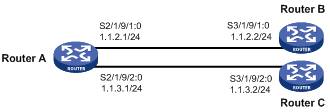
As shown in Figure 1, configure PBR on Router A, so that all TCP packets are forwarded to next hop 1.1.2.2 and other packets are forwarded according to the routing table.
Router A is directly connected to Router B and Router C. Router B and Router C are unreachable to each other.
Configuration procedure
1. Configure Router A:
# Define ACL 3101 to match TCP packets.
<RouterA> system-view
[RouterA] acl number 3101
[RouterA-acl-adv-3101] rule permit tcp
[RouterA-acl-adv-3101] quit
# Define Node 5 of policy aaa, so that TCP packets are forwarded via next hop 1.1.2.2.
[RouterA] policy-based-route aaa permit node 5
[RouterA-pbr-aaa-5] if-match acl 3101
[RouterA-pbr-aaa-5] apply ip-address next-hop 1.1.2.2
[RouterA-pbr-aaa-5] quit
# Apply policy aaa to Router A.
[RouterA] ip local policy-based-route aaa
# Configure the IP addresses of the serial ports.
[RouterA] interface Serial 2/1/9/1:0
[RouterA-Serial2/1/9/1:0] ip address 1.1.2.1 255.255.255.0
[RouterA-Serial2/1/9/1:0] quit
[RouterA] interface Serial 2/1/9/2:0
[RouterA-Serial2/1/9/2:0] ip address 1.1.3.1 255.255.255.0
2. Configure Router B:
# Configure the IP address of the serial port.
<RouterB> system-view
[RouterB] interface Serial 3/1/9/1:0
[RouterB-Serial3/1/9/1:0] ip address 1.1.2.2 255.255.255.0
[RouterB-Serial3/1/9/1:0] quit
3. Configure Router C:
# Configure the IP address of the serial port.
<RouterC> system-view
[RouterC] interface Serial 3/1/9/2:0
[RouterC-Serial3/1/9/2:0] ip address 1.1.3.2 255.255.255.0
[RouterC-Serial3/1/9/2:0] quit
4. Verify the configuration:
# Telnet to Router B (1.1.2.2/24) from Router A. The operation succeeds.
<RouterA> telnet 1.1.2.2
Trying 1.1.2.2 ...
Press CTRL+K to abort
Connected to 1.1.2.2 ...
******************************************************************************
* Copyright (c) 2004-2009 Hangzhou H3C Tech. Co., Ltd. All rights reserved. *
* Without the owner's prior written consent, *
* no decompiling or reverse-engineering shall be allowed. *
******************************************************************************
# Telnet to Router C (1.1.3.2/24) from Router A. The operation fails.
<RouterA> telnet 1.1.3.2
Trying 1.1.3.2 ...
Press CTRL+K to abort
Can't connect to the remote host!
# Ping Router C (1.1.3.2/24) from Router A. The operation succeeds.
<RouterA> ping 1.1.3.2
PING 1.1.3.2: 56 data bytes, press CTRL_C to break
Reply from 1.1.3.2: bytes=56 Sequence=1 ttl=255 time=2 ms
Reply from 1.1.3.2: bytes=56 Sequence=2 ttl=255 time=1 ms
Reply from 1.1.3.2: bytes=56 Sequence=3 ttl=255 time=1 ms
Reply from 1.1.3.2: bytes=56 Sequence=4 ttl=255 time=1 ms
Reply from 1.1.3.2: bytes=56 Sequence=5 ttl=255 time=1 ms
--- 1.1.3.2 ping statistics ---
5 packet(s) transmitted
5 packet(s) received
0.00% packet loss
round-trip min/avg/max = 1/1/2 ms
Telnet uses TCP, and ping uses ICMP. The preceding results show that all TCP packets of Router A are forwarded via next hop 1.1.2.2, and other packets are forwarded according to the routing table. The PBR configuration is effective.
Configuring interface PBR based on packet type
Network requirements
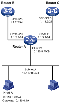
As shown in Figure 2, configure PBR on Router A, so that TCP packets arriving on GigabitEthernet 3/1/1 are forwarded via next hop 1.1.2.2 and other packets are forwarded according to the routing table.
Configuration procedure
|
|
NOTE: In this example, static routes are configured to ensure the reachability among routers. |
1. Configure Router A:
# Define ACL 3101 to match TCP packets.
<RouterA> system-view
[RouterA] acl number 3101
[RouterA-acl-adv-3101] rule permit tcp
[RouterA-acl-adv-3101] quit
# Define Node 5 of policy aaa so that TCP packets are forwarded via next hop 1.1.2.2.
[RouterA] policy-based-route aaa permit node 5
[RouterA-pbr-aaa-5] if-match acl 3101
[RouterA-pbr-aaa-5] apply ip-address next-hop 1.1.2.2
[RouterA-pbr-aaa-5] quit
# Apply the policy aaa to GigabitEthernet 3/1/1.
[RouterA] interface GigabitEthernet 3/1/1
[RouterA-GigabitEthernet3/1/1] ip address 10.110.0.10 255.255.255.0
[RouterA-GigabitEthernet3/1/1] ip policy-based-route aaa
[RouterA-GigabitEthernet3/1/1] quit
# Configure the IP addresses of the serial ports.
[RouterA] interface Serial 2/1/9/2:0
[RouterA-Serial2/1/9/2:0] ip address 1.1.2.1 255.255.255.0
[RouterA-Serial2/1/9/2:0] quit
[RouterA] interface Serial 2/1/9/1:0
[RouterA-Serial2/1/9/1:0] ip address 1.1.3.1 255.255.255.0
2. Configure Router B:
# Configure a static route to subnet 10.110.0.0/24.
<RouterB> system-view
[RouterB] ip route-static 10.110.0.0 24 1.1.2.1
# Configure the IP address of the serial port.
[RouterB] interface Serial 3/1/9/2:0
[RouterB-Serial3/1/9/2:0] ip address 1.1.2.2 255.255.255.0
[RouterB-Serial3/1/9/2:0] quit
3. Configure Router C:
# Configure a static route to subnet 10.110.0.0/24.
<RouterC> system-view
[RouterC] ip route-static 10.110.0.0 24 1.1.3.1
# Configure the IP address of the serial port.
[RouterC] interface Serial 3/1/9/1:0
[RouterC-Serial3/1/9/1:0] ip address 1.1.3.2 255.255.255.0
[RouterC-Serial3/1/9/1:0] quit
4. Verify the configuration:
Configure the IP address of Host A as 10.110.0.20/24, and the gateway as 10.110.0.10.
On Host A, telnet to Router B (1.1.2.2) that is directly connected to Router A. The operation succeeds.
On Host A, telnet to Router C (1.1.3.2) that is directly connected to Router A. The operation fails.
Ping Router C from Host A. The operation succeeds.
Telnet uses TCP, and ping uses ICMP. The preceding results show that all TCP packets arriving on GigabitEthernet 3/1/1 of Router A are forwarded via next hop 1.1.2.2, and other packets are forwarded via next hop 1.1.3.2 on Router C. The PBR configuration is effective.