- Table of Contents
-
- 06-Layer 3 - IP Routing Configuration Guide
- 00-Preface
- 01-IP Routing Basics
- 02-Static Routing Configuration
- 03-RIP Configuration
- 04-OSPF Configuration
- 05-IS-IS Configuration
- 06-BGP Configuration
- 07-Policy-Based Routing Configuration
- 08-IPv6 Static Routing Configuration
- 09-RIPng Configuration
- 10-OSPFv3 Configuration
- 11-IPv6 IS-IS Configuration
- 12-IPv6 BGP Configuration
- 13-IPv6 Policy-Based Routing Configuration
- 14-Routing Policy Configuration
- 15-QoS Policy Routing Configuration
- Related Documents
-
| Title | Size | Download |
|---|---|---|
| 02-Static Routing Configuration | 255.04 KB |
Contents
Static route configuration items
Detecting reachability of the static route’s next hop
Detecting next hop reachability through BFD
Detecting next hop reachability through track
Configuring BFD for static routes
Displaying and maintaining static routes
Static route configuration examples
Basic static route configuration example
Static route FRR configuration example
BFD for static routes configuration example (direct session)
BFD for static routes configuration example (indirect session)
Introduction
Static route
Static routes are manually configured. If a network’s topology is simple, you only need to configure static routes for the network to work properly. The proper configuration and usage of static routes can improve network performance and ensure bandwidth for important network applications.
The disadvantage of using static routes is that they cannot adapt to network topology changes. If a fault or a topological change occurs in the network, the routes will be unreachable and the network breaks. The network administrator has to modify the static routes manually.
Default route
Without a default route, a packet that does not match any routing entries is discarded.
A default route is used to forward packets that match no entry in the routing table. It can be configured in either of the following ways:
· The network administrator can configure a default route with both destination and mask being 0.0.0.0. The router forwards any packet whose destination address fails to match any entry in the routing table to the next hop of the default static route.
· Some dynamic routing protocols, such as OSPF, RIP and IS-IS, can also generate a default route. For example, an upstream router running OSPF can generate a default route and advertise it to other routers, which install the default route with the next hop being the upstream router.
Static route configuration items
Before you configure a static route, you must know the following concepts:
· Destination address and mask
In the ip route-static command, an IPv4 address is in dotted decimal format and a mask can be either in dotted decimal format or in the form of mask length—the number of consecutive 1s in the mask.
· Output interface and next hop address
When configuring a static route, specify either the output interface, next hop address, or both depending on the specific occasion. The next hop address cannot be a local interface IP address; otherwise, the route configuration will not take effect.
In fact, each route lookup operation has to find the next hop to resolve the destination link layer address.
When you specify the output interface, follow these guidelines:
¡ If the output interface is a Null 0 interface, no next hop address is required.
¡ If the output interface is a point-to-point interface, no next hop address is required. You need not change the configuration even if the peer’s address changes. For example, a PPP interface obtains the peer’s IP address through PPP negotiation, so you need only specify the output interface.
¡ If the output interface is an NBMA or P2MP interface, which support point-to-multipoint network, the IP address to link layer address mapping must be established. Therefore, H3C recommends you to configure both the next hop IP address and the output interface.
¡ H3C does not recommend you to specify a broadcast interface (such as an Ethernet interface or VLAN interface) as the output interface, because a broadcast interface may have multiple next hops. If you have to do so, you must specify the corresponding next hop for the output interface.
· Other attributes
You can configure different priorities for different static routes so that route management policies can be more flexible. For example, specifying the same priority for different routes to the same destination enables load sharing, but specifying different priorities for these routes enables route backup.
Configuring a static route
Configuration prerequisites
Before you configure a static route, complete the following tasks:
· Configure the physical parameters for related interfaces.
· Configure the link-layer attributes for related interfaces.
· Configure the IP addresses for related interfaces.
Configuration procedure
To configure a static route:
|
Step |
Command |
Remarks |
|
1. Enter system view. |
system-view |
N/A |
|
2. Configure a static route. |
·
Approach 1: ·
Approach 2: |
By default, preference for static routes is 60, tag is 0, and no description information is configured. Do not specify the permanent and track keywords simultaneously. If the outgoing interface is down, the permanent static route is still active. |
|
3. Configure the default preference for static routes. |
ip route-static default-preference default-preference-value |
Optional. 60 by default. |
|
|
NOTE: · When you configure a static route, the static route does not take effect if you specify the next hop address first and then configure it as the IP address of a local interface, such as Ethernet interface and VLAN interface. · If you do not specify the preference when configuring a static route, the default preference will be used. Reconfiguring the default preference applies only to newly created static routes. · You can flexibly control static routes by configuring tag values and using the tag values in the routing policy. · If the destination IP address and mask are both configured as 0.0.0.0 with the ip route-static command, the route is the default route. · For detailed information about track, see High Availability Configuration Guide. |
Detecting reachability of the static route’s next hop
If a static route fails due to a topology change or a fault, traffic over the route is interrupted. To improve reliability, the system must detect the reachability of the static route’s next hop and switch to a backup route once the next hop is unreachable.
There are two methods for this purpose. Only one of the two methods can be used at a time.
Detecting next hop reachability through BFD
Bidirectional forwarding detection (BFD) provides a general-purpose, standard, medium- and protocol-independent fast failure detection mechanism. It can uniformly and quickly detect the failures of the bidirectional forwarding paths between two routers for upper-layer protocols, such as routing protocols and Multiprotocol Label Switching (MPLS). For more information about BFD, see High Availability Configuration Guide.
After a static route is configured, you can enable BFD to detect the reachability of the static route's next hop.
Network requirements
To detect the reachability of the static route's next hop through BFD, you must enable BFD first. For BFD configuration, see High Availability Configuration Guide.
Configuration procedure
To detect reachability of the static route’s next hop through BFD:
|
Step |
Command |
Remarks |
|
1. Enter system view. |
system-view |
N/A |
|
2. Detect reachability of the static route’s next hop through BFD. |
· Approach 1: · Approach 2: |
Not configured by default |
|
|
NOTE: · To implement BFD in the control-packet mode, the remote end must create a BFD session; otherwise the BFD function cannot work. To implement BFD in the echo-packet mode, the BFD function can work without the remote end needing to create any BFD session. · If a route flap occurs, enabling BFD may worsen the flapping. Be cautious for use of this feature. |
Detecting next hop reachability through track
If you specify the next hop but not outgoing interface when configuring a static route, you can associate the static route with a track entry to check the static route validity.
· When the track entry is positive, the static route's next hop is reachable and the static route takes effect;
· When the track entry is negative, the static route's next hop is unreachable and the static route is invalid.
For more information about track, see High Availability Configuration Guide.
Network requirements
To detect the reachability of a static route's next hop through a Track entry, you must create a Track first. For the Track configuration procedure, see High Availability Configuration Guide.
Configuration procedure
To detect the reachability of a static route's next hop through Track:
|
Step |
Command |
Remarks |
|
1. Enter system view. |
system-view |
N/A |
|
2. Associate the static route with a track entry. |
· Approach 1: · Approach 2: |
Not configured by default |
|
|
NOTE: · To configure this feature for an existing static route, simply associate the static route with a track entry. For a non-existent static route, configure it and associate it with a Track entry. · If the track module uses NQA to detect the reachability of the private network static route's next hop, the VPN instance number of the static route's next hop must be identical to that configured in the NQA test group. · If a static route needs route recursion, the associated track entry must monitor the next hop of the recursive route instead of that of the static route. Otherwise, a valid route may be mistakenly considered invalid. |
Configuring BFD for static routes
A dynamic routing protocol notifies BFD of its neighbor information. BFD uses such information to establish sessions with neighbors by sending BFD control packets. Static routing has no neighbor discovery mechanism. This section describes how static routing implements BFD.
BFD control packet mode
To use BFD control packets for bidirectional detection between two devices, enable BFD control packet mode for each device’s static route destined to the peer.
To configure a static route and enable BFD control packet mode for it, specify an outbound interface and a direct next hop—BFD establishes a direct session, or specify an indirect next hop and a specific BFD packet source address—BFD establishes an indirect session—for the static route.
To configure a static route with BFD control packet mode enabled (direct session):
|
Step |
Command |
Remarks |
|
1. Enter system view. |
system-view |
N/A |
|
2. Configure a static route and enable BFD control packet mode for it. |
·
Approach 1: ·
Approach 2: |
Use either approach. |
To configure a static route with BFD control packet mode enabled (indirect session):
|
Step |
Command |
Remarks |
|
1. Enter system view. |
system-view |
N/A |
|
2. Configure a static route and enable BFD control packet mode for it. |
·
Approach 1: ·
Approach 2: |
Use either approach. |
BFD echo packet mode
With BFD echo packet mode enabled for a static route, the local device sends BFD echo packets to the peer, which loops it back to test the link.
To configure BFD echo packet mode for static routes:
|
Step |
Command |
Remarks |
|
1. Enter system view. |
system-view |
N/A |
|
2. Configure the source address of echo packets. |
bfd echo-source-ip ip-address |
Not configured by default |
|
3. Enable BFD echo packet mode for static routes. |
·
Approach 1: ·
Approach 2: |
Use either approach. |
|
|
NOTE: · If route flaps occur, enabling BFD could worsen them. · For the echo mode, only one end needs to establish the BFD session, and the source address of echo packets must be configured. · BFD cannot be used for a static route with the outbound interface having the spoofing attribute. · BFD can be used for static routes with direct next hops rather than indirect next hops. · A BFD session is established at only one end when the echo mode is used. · The BFD echo packet mode is not supported on tunnel interfaces at present. · For how to configure static routing, see the chapter “Configuring static routing.” |
Configuring static route FRR
When a link or a router fails, the packets on the path may be discarded, or a routing loop occurs. To avoid such problems, you can enable static route fast reroute (FRR).
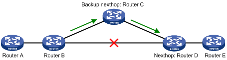
As shown in Figure 1, upon a link failure, FRR designates a backup next hop by using a routing policy for routes matching the specified criteria. Packets are directed to the backup next hop to avoid traffic interruption.
Configuration prerequisites
Create a routing policy to be referenced by FRR and use the apply fast-reroute backup-interface command to specify a backup next hop in the routing policy. For more information about the command and routing policy configurations, see the chapter “Configuring routing policies.”
Configuration procedure
To configure static route FRR:
|
Step |
Command |
Remarks |
|
1. Enter system view. |
system-view |
N/A |
|
2. Configure the source address of echo packets. |
bfd echo-source-ip ip-address |
Not configured by default |
|
3. Configure static route FRR. |
ip route-static [ vpn-instance vpn-instance-name ] fast-reroute route-policy route-policy-name |
Not configured by default |
|
|
NOTE: · Static route FRR takes effect only for static routes that have both the outbound interface and next hop specified. · Do not use FRR and BFD at the same time. |
Displaying and maintaining static routes
|
Task |
Command |
Remarks |
|
Display information of static routes. |
display ip routing-table protocol static [ inactive | verbose ] [ | { begin | exclude | include } regular-expression ] |
Available in any view |
|
Delete all the static routes. |
delete [ vpn-instance vpn-instance-name ] static-routes all |
Available in system view |
|
|
NOTE: For more information about the display ip routing-table protocol static [ inactive | verbose ] [ | { begin | exclude | include } regular-expression ] command, see the chapter “IP routing basics configuration commands.” |
Static route configuration examples
Basic static route configuration example
Network requirements
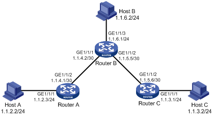
The routers’ interfaces and the hosts’ IP addresses and masks are shown in Figure 2. Static routes are required for interconnections between any two hosts.
Configuration procedure
1. Configuring IP addresses for interfaces. (Details not shown)
2. Configuring static routes:
# Configure a default route on Router A.
<RouterA> system-view
[RouterA] ip route-static 0.0.0.0 0.0.0.0 1.1.4.2
# Configure two static routes on Router B.
<RouterB> system-view
[RouterB] ip route-static 1.1.2.0 255.255.255.0 1.1.4.1
[RouterB] ip route-static 1.1.3.0 255.255.255.0 1.1.5.6
# Configure a default route on Router C.
<RouterC> system-view
[RouterC] ip route-static 0.0.0.0 0.0.0.0 1.1.5.5
3. Configure the hosts:
4. Verify the configuration:
# Display the IP routing table of Router A.
[RouterA] display ip routing-table
Routing Tables: Public
Destinations : 7 Routes : 7
Destination/Mask Proto Pre Cost NextHop Interface
0.0.0.0/0 Static 60 0 1.1.4.2 GE1/1/2
1.1.2.0/24 Direct 0 0 1.1.2.3 GE1/1/1
1.1.2.3/32 Direct 0 0 127.0.0.1 InLoop0
1.1.4.0/30 Direct 0 0 1.1.4.1 GE1/1/2
1.1.4.1/32 Direct 0 0 127.0.0.1 InLoop0
127.0.0.0/8 Direct 0 0 127.0.0.1 InLoop0
127.0.0.1/32 Direct 0 0 127.0.0.1 InLoop0
# Display the IP routing table of Router B.
[RouterB] display ip routing-table
Routing Tables: Public
Destinations : 10 Routes : 10
Destination/Mask Proto Pre Cost NextHop Interface
1.1.2.0/24 Static 60 0 1.1.4.1 GE1/1/1
1.1.3.0/24 Static 60 0 1.1.5.6 GE1/1/2
1.1.4.0/30 Direct 0 0 1.1.4.2 GE1/1/1
1.1.4.2/32 Direct 0 0 127.0.0.1 InLoop0
1.1.5.4/30 Direct 0 0 1.1.5.5 GE1/1/2
1.1.5.5/32 Direct 0 0 127.0.0.1 InLoop0
127.0.0.0/8 Direct 0 0 127.0.0.1 InLoop0
127.0.0.1/32 Direct 0 0 127.0.0.1 InLoop0
1.1.6.0/24 Direct 0 0 1.1.6.1 GE1/1/3
1.1.6.1/32 Direct 0 0 127.0.0.1 InLoop0
# Use the ping command on Host B to check the reachability of Host A, assuming Windows XP runs on the two hosts.
C:\Documents and Settings\Administrator> ping 1.1.2.2
Pinging 1.1.2.2 with 32 bytes of data:
Reply from 1.1.2.2: bytes=32 time=1ms TTL=128
Reply from 1.1.2.2: bytes=32 time=1ms TTL=128
Reply from 1.1.2.2: bytes=32 time=1ms TTL=128
Reply from 1.1.2.2: bytes=32 time=1ms TTL=128
Ping statistics for 1.1.2.2:
Packets: Sent = 4, Received = 4, Lost = 0 (0% loss),
Approximate round trip times in milli-seconds:
Minimum = 1ms, Maximum = 1ms, Average = 1ms
# Use the tracert command on Host B to check the reachability of Host A.
C:\Documents and Settings\Administrator>tracert 1.1.2.2
Tracing route to 1.1.2.2 over a maximum of 30 hops
1 <1 ms <1 ms <1 ms 1.1.6.1
2 <1 ms <1 ms <1 ms 1.1.4.1
3 1 ms <1 ms <1 ms 1.1.2.2
Trace complete.
Static route FRR configuration example
Network requirements
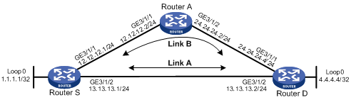
Router S, Router A, and Router D are interconnected through static routes, as illustrated in Figure 3. Configure static route FRR so that when the link between Router S and Router D fails, traffic can be switched to Link B immediately.
Configuration procedure
1. Configure IP addresses for the interfaces on each router and configure static routes:
Follow Figure 3 to configure the IP address and subnet mask of each interface on the routers. (Details not shown)
Configure static routes on Router S, Router A, and Router D so that Router S can reach Loopback 0 on Router D and Router D can reach Loopback 0 on Router S.
# Configure a static route on Router S.
<RouterS> system-view
[RouterS] ip route-static 4.4.4.4 32 GigabitEthernet 3/1/2 13.13.13.2
[RouterS] ip route-static 4.4.4.4 32 GigabitEthernet 3/1/2 12.12.12.2 preference 65
# Configure a static route on Router D.
<RouterD> system-view
[RouterD] ip route-static 1.1.1.1 32 GigabitEthernet 3/1/2 13.13.13.1
[RouterD] ip route-static 1.1.1.1 32 GigabitEthernet 3/1/2 24.24.24.2 preference 65
# Configure a static route on Router A.
<RouterA> system-view
[RouterA] ip route-static 4.4.4.4 32 GigabitEthernet 3/1/2 24.24.24.4
[RouterA] ip route-static 1.1.1.1 32 GigabitEthernet 3/1/1 12.12.12.1
2. Configure static route FRR:
# Configure Router S.
[RouterS] bfd echo-source-ip 1.1.1.1
[RouterS] ip ip-prefix abc index 10 permit 4.4.4.4 32
[RouterS] route-policy frr permit node 10
[RouterS-route-policy] if-match ip-prefix abc
[RouterS-route-policy] apply fast-reroute backup-interface GigabitEthernet 3/1/1 backup-nexthop 12.12.12.2
[RouterS-route-policy] quit
[RouterS] ip route-static fast-reroute route-policy frr
# Configure Router D.
[RouterD] bfd echo-source-ip 4.4.4.4
[RouterD] ip ip-prefix abc index 10 permit 1.1.1.1 32
[RouterD] route-policy frr permit node 10
[RouterD-route-policy] if-match ip-prefix abc
[RouterD-route-policy] apply fast-reroute backup-interface GigabitEthernet 3/1/1 backup-nexthop 24.24.24.2
[RouterD-route-policy] quit
[RouterD] ip route-static fast-reroute route-policy frr
3. Verify the configuration:
# Display route 4.4.4.4/32 on Router S to view the backup next hop information.
[RouterS] display ip routing-table 4.4.4.4 verbose
Routing Table : Public
Summary Count : 1
Destination: 4.4.4.4/32
Protocol: Static Process ID: 0
Preference: 60 Cost: 0
IpPrecedence: QosLcID:
NextHop: 13.13.13.2 Interface: GigabitEthernet3/1/2
BkNextHop: 12.12.12.2 BkInterface: GigabitEthernet3/1/1
RelyNextHop: 0.0.0.0 Neighbor : 0.0.0.0
Tunnel ID: 0x0 Label: NULL
State: Active Adv Age: 00h01m27s
Tag: 0
# Display route 1.1.1.1/32 on Router D to view the backup next hop information.
[RouterS] display ip routing-table 1.1.1.1 verbose
Routing Table : Public
Summary Count : 1
Destination: 1.1.1.1/32
Protocol: Static Process ID: 0
Preference: 60 Cost: 0
IpPrecedence: QosLcID:
NextHop: 13.13.13.1 Interface: GigabitEthernet3/1/2
BkNextHop: 24.24.24.2 BkInterface: GigabitEthernet3/1/1
RelyNextHop: 0.0.0.0 Neighbor : 0.0.0.0
Tunnel ID: 0x0 Label: NULL
State: Active Adv Age: 00h01m27s
Tag: 0
BFD for static routes configuration example (direct session)
Network requirements
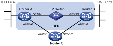
As shown in Figure 4, configure a static route to subnet 120.1.1.0/24 on Router A and configure a static route to subnet 121.1.1.0/24 on Router B. Enable BFD for both routes so that when the link between Router A and Router B through the Layer 2 switch fails, BFD can detect the failure immediately and Router A and Router B can communicate through Router C.
|
Device |
Interface |
IP address |
Device |
Interface |
IP address |
|
Router A |
GE3/1/1 |
12.1.1.1/24 |
Router B |
GE3/1/1 |
12.1.1.2/24 |
|
|
GE3/1/2 |
10.1.1.102/24 |
|
GE3/1/2 |
13.1.1.1/24 |
|
Router C |
GE3/1/1 |
10.1.1.100/24 |
|
|
|
|
|
GE3/1/2 |
13.1.1.2/24 |
|
|
|
Configuration procedure
1. Configure IP addresses for the interfaces. (Details not shown)
2. Configure BFD:
# Configure static routes on Router A and enable BFD control packet mode for the static route through the Layer 2 switch.
<RouterA> system-view
[RouterA] interface GigabitEthernet 3/1/1
[RouterA-GigabitEthernet3/1/1] bfd min-transmit-interval 500
[RouterA-GigabitEthernet3/1/1] bfd min-receive-interval 500
[RouterA-GigabitEthernet3/1/1] bfd detect-multiplier 9
[RouterA-GigabitEthernet3/1/1] quit
[RouterA] ip route-static 120.1.1.0 24 GigabitEthernet 3/1/1 12.1.1.2 bfd control-packet
[RouterA] ip route-static 120.1.1.0 24 GigabitEthernet 3/1/2 10.1.1.100 preference 65
[RouterA] quit
# Configure static routes on Router B and enable BFD control packet mode for the static route through the Layer 2 switch.
<RouterB> system-view
[RouterB] interface GigabitEthernet 3/1/1
[RouterB-GigabitEthernet3/1/1] bfd min-transmit-interval 500
[RouterB-GigabitEthernet3/1/1] bfd min-receive-interval 500
[RouterB-GigabitEthernet3/1/1] bfd detect-multiplier 9
[RouterB-GigabitEthernet3/1/1] quit
[RouterB] ip route-static 121.1.1.0 24 GigabitEthernet 3/1/1 12.1.1.1 bfd control-packet
[RouterB] ip route-static 121.1.1.0 24 GigabitEthernet 3/1/2 13.1.1.2 preference 65
[RouterB] quit
3. Verify the configuration:
The following operations are performed on Router A. The operations on Router B are similar.
<RouterA> display bfd session
Total Session Num: 1 Init Mode: Active
Session Working Under Ctrl Mode:
LD/RD SourceAddr DestAddr State Holdtime Interface
4/7 12.1.1.1 12.1.1.2 Up 2000ms GigabitEthernet3/1/1
# Display the static route information of Router A.
<RouterA> display ip routing-table protocol static
Public Routing Table : Static
Summary Count : 2
Static Routing table Status : < Active>
Summary Count : 1
Destination/Mask Proto Pre Cost NextHop Interface
120.1.1.0/24 Static 60 0 12.1.1.2 GE3/1/1
Direct Routing table Status : <Inactive>
Summary Count : 1
Destination/Mask Proto Pre Cost NextHop Interface
120.1.1.0/24 Static 65 0 10.1.1.100 GE3/1/2
# Enable BFD debugging on Router A. When the link between Router A and the switch fails, Router A can detect the failure.
<RouterA> debugging bfd event
<RouterA> debugging bfd scm
<RouterA> terminal debugging
%Jul 27 10:18:18:672 2007 RouterA BFD/4/LOG:Sess[12.1.1.1/12.1.1.2, GigabitEthernet3/1/1,Ctrl], Sta: UP->DOWN, Diag: 1
*Jul 27 10:18:18:672 2007 RouterA BFD/7/EVENT:Send sess-down Msg, [Src:12.1.1.1,Dst:12.1.1.2,GigabitEthernet3/1/1,Ctrl], instance:0, protocol:STATIC
*Jul 27 10:18:19:172 2007 RouterA BFD/7/EVENT:Receive Delete-sess, [Src:12.1.1.1,Dst:12.1.1.2,GigabitEthernet3/1/1,Ctrl], Direct, Instance:0x0, Proto:STATIC
*Jul 27 10:18:19:172 2007 RouterA BFD/7/EVENT:Notify driver to stop receiving bf
# Display the static route information on Router A again. Router A communicates with Router B over the static route passing Router C now.
<RouterA> display ip routing-table protocol static
Public Routing Table : Static
Summary Count : 2
Static Routing table Status : < Active>
Summary Count : 1
Destination/Mask Proto Pre Cost NextHop Interface
120.1.1.0/24 Static 65 0 10.1.1.100 GE3/1/2
Static Routing table Status : < Inactive>
Summary Count : 1
Destination/Mask Proto Pre Cost NextHop Interface
120.1.1.0/24 Static 60 0 12.1.1.2 GE3/1/1
BFD for static routes configuration example (indirect session)
Network requirements
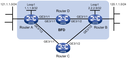
As shown in Figure 5, Router A has a route to interface Loopback1 (2.2.2.9/32) on Router B, with the outbound interface GigabitEthernet 3/1/1. Router B has a route to interface Loopback1 (1.1.1.9/32) on Router A, with the outbound interface GigabitEthernet 3/1/1. Router D has a route to 1.1.1.9/32, with the outbound interface GigabitEthernet 3/1/1, and a route to 2.2.2.9/32, with the outbound interface GigabitEthernet 3/1/2.
Configure a static route to subnet 120.1.1.0/24 on Router A and configure a static route to subnet 121.1.1.0/24 on Router B. Enable BFD for both routes so that when the link between Router A and Router B through Router D fails, BFD can detect the failure immediately and Router A and Router B can communicate through Router C.
|
Device |
Interface |
IP address |
Device |
Interface |
IP address |
|
Router A |
GE3/1/1 |
12.1.1.1/24 |
Router B |
GE3/1/1 |
11.1.1.2/24 |
|
|
GE3/1/2 |
10.1.1.102/24 |
|
GE3/1/2 |
13.1.1.2/24 |
|
|
Loop1 |
1.1.1.9/32 |
|
Loop1 |
2.2.2.9/32 |
|
Router C |
GE3/1/1 |
10.1.1.100/24 |
Router D |
GE3/1/1 |
12.1.1.2/24 |
|
|
GE3/1/2 |
13.1.1.2/24 |
|
GE3/1/2 |
11.1.1.1/24 |
Configuration procedure
1. Configure IP addresses for the interfaces. (Details not shown)
2. Configure BFD:
# Configure static routes on Router A and enable BFD control packet mode for the static route through Router D.
<RouterA> system-view
[RouterA] interface loopback 1
[RouterA-LoopBack1] bfd min-transmit-interval 500
[RouterA-LoopBack1] bfd min-receive-interval 500
[RouterA-LoopBack1] bfd detect-multiplier 9
[RouterA-LoopBack1] quit
[RouterA] ip route-static 120.1.1.0 24 2.2.2.9 bfd control-packet bfd-source 1.1.1.9
[RouterA] ip route-static 120.1.1.0 24 GigabitEthernet 3/1/2 10.1.1.100 preference 65
[RouterA] quit
# Configure static routes on Router B and enable BFD control packet mode for the static route through Router D.
<RouterB> system-view
[RouterB] interface loopback 1
[RouterB-LoopBack1] bfd min-transmit-interval 500
[RouterB-LoopBack1] bfd min-receive-interval 500
[RouterB-LoopBack1] bfd detect-multiplier 9
[RouterB-LoopBack1] quit
[RouterB] ip route-static 121.1.1.0 24 1.1.1.9 bfd control-packet bfd-source 2.2.2.9
[RouterB] ip route-static 121.1.1.0 24 GigabitEthernet 3/1/2 13.1.1.2 preference 65
[RouterB] quit
3. Verify the configuration:
The following operations are performed on Router A. The operations on Router B are similar.
# Display the BFD session information of Router A.
<RouterA> display bfd session
Total session number: 1 Up session number: 0 Init mode: Active
IPv4 session working under Ctrl mode:
LD/RD SourceAddr DestAddr State Holdtime Interface
4/7 1.1.1.9 2.2.2.9 Up 2000ms Loop1
# Display the static route information of Router A.
<RouterA> display ip routing-table protocol static
Public Routing Table : Static
Summary Count : 2
Static Routing table Status : < Active>
Summary Count : 1
Destination/Mask Proto Pre Cost NextHop Interface
120.1.1.0/24 Static 60 0 2.2.2.9 GE3/1/1
Static Routing table Status : <Inactive>
Summary Count : 1
Destination/Mask Proto Pre Cost NextHop Interface
120.1.1.0/24 Static 65 0 10.1.1.100 GE3/1/2
# Enable BFD debugging on Router A. When the link between Router A and Router D fails, Router A can detect the failure.
<RouterA> debugging bfd event
<RouterA> debugging bfd scm
<RouterA> terminal debugging
%Oct 10 10:18:18:672 2010 RouterA BFD/4/LOG:Sess[1.1.1.9/2.2.2.9, Loop1,Ctrl], Sta: UP->DOWN, Diag: 1
*Oct 10 10:18:18:672 2010 RouterA BFD/7/EVENT:Send sess-down Msg, [Src:1.1.1.9,Dst:2.2.2.9,Loop1,Ctrl], instance:0, protocol:STATIC
# Display the static route information on Router A again. Router A communicates with Router B over the static route passing Router C now.
<RouterA> display ip routing-table protocol static
Public Routing Table : Static
Summary Count : 2
Static Routing table Status : < Active>
Summary Count : 1
Destination/Mask Proto Pre Cost NextHop Interface
120.1.1.0/24 Static 65 0 10.1.1.100 GE3/1/2
Static Routing table Status : < Inactive>
Summary Count : 1
Destination/Mask Proto Pre Cost NextHop Interface
120.1.1.0/24 Static 60 0 2.2.2.9