- Table of Contents
-
- 06-Layer 3 - IP Routing Configuration Guide
- 00-Preface
- 01-IP Routing Basics
- 02-Static Routing Configuration
- 03-RIP Configuration
- 04-OSPF Configuration
- 05-IS-IS Configuration
- 06-BGP Configuration
- 07-Policy-Based Routing Configuration
- 08-IPv6 Static Routing Configuration
- 09-RIPng Configuration
- 10-OSPFv3 Configuration
- 11-IPv6 IS-IS Configuration
- 12-IPv6 BGP Configuration
- 13-IPv6 Policy-Based Routing Configuration
- 14-Routing Policy Configuration
- 15-QoS Policy Routing Configuration
- Related Documents
-
| Title | Size | Download |
|---|---|---|
| 11-IPv6 IS-IS Configuration | 162.25 KB |
Configuring IPv6 IS-IS basic functions
Configuring IPv6 IS-IS routing information control
Configuring BFD for IPv6 IS-IS
Displaying and maintaining IPv6 IS-IS
IPv6 IS-IS configuration examples
IPv6 IS-IS basic configuration example
|
|
NOTE: · IPv6 IS-IS supports all IPv4 IS-IS features, but advertises IPv6 routing information. This document describes only IPv6 IS-IS exclusive configuration tasks. For other configuration tasks, see the chapter “Configuring IS-IS.” · The term router in this document refers to both routers and Layer 3 switches. |
Introduction to IPv6 IS-IS
The IS-IS routing protocol (Intermediate System-to-Intermediate System intra-domain routing information exchange protocol) supports multiple network protocols, including IPv6. The international engineer task force (IETF) defines two type-length-values (TLVs) and a new network layer protocol identifier (NLPID) to enable IS-IS to support IPv6.
TLV is a variable-length field in the link state PDU or link state packet (LSP). The two TLVs are:
· IPv6 Reachability—Defines the prefix, metric of routing information to indicate network reachability, and has a type value of 236 (0xEC).
· IPv6 Interface Address—Same as the “IP Interface Address” TLV in IPv4 ISIS, except that the 32-bit IPv4 address is translated to the 128-bit IPv6 address.
The NLPID is an 8-bit field that identifies which network layer protocol is supported. For IPv6, the NLPID is 142 (0x8E), which must be carried in hello packets sent by a router that supports IPv6 IS-IS.
For information about IS-IS, see the chapter “Configuring IS-IS.”
Configuring IPv6 IS-IS basic functions
|
|
NOTE: You can implement IPv6 inter-networking through configuring IPv6 IS-IS in IPv6 network environment. |
Configuration prerequisites
Before the configuration, complete the following tasks:
· Enable IPv6 globally.
· Configure IP addresses for interfaces, and make sure that all neighboring nodes are reachable to each other.
· Enable IS-IS.
Configuration procedure
To configure the basic functions of IPv6 IS-IS:
|
Step |
Command |
Remarks |
|
1. Enter system view. |
system-view |
N/A |
|
2. Enable an IS-IS process and enter IS-IS view. |
isis [ process-id ] [ vpn-instance vpn-instance-name ] |
Not enabled by default |
|
3. Configure the network entity title for the IS-IS process. |
network-entity net |
Not configured by default |
|
4. Enable IPv6 for the IS-IS process. |
ipv6 enable |
Disabled by default |
|
5. Return to system view. |
quit |
N/A |
|
6. Enter interface view. |
interface interface-type interface-number |
N/A |
|
7. Enable IPv6 for an IS-IS process on the interface. |
isis ipv6 enable [ process-id ] |
Disabled by default |
Configuring IPv6 IS-IS routing information control
Configuration prerequisites
Complete the IPv6 IS-IS basic function configuration before configuring this task.
Configuration procedure
To configure IPv6 IS-IS routing information control:
|
Step |
Command |
Remarks |
|
1. Enter system view. |
system-view |
N/A |
|
2. Enter IS-IS view. |
isis [ process-id ] [ vpn-instance vpn-instance-name ] |
N/A |
|
3. Define the priority for IPv6 IS-IS routes. |
ipv6 preference { route-policy route-policy-name | preference } * |
Optional. 15 by default. |
|
4. Configure an IPv6 IS-IS summary route. |
ipv6 summary ipv6-prefix prefix-length [ avoid-feedback | generate_null0_route | [ level-1 | level-1-2 | level-2 ] | tag tag ] * |
Optional. Not configured by default. |
|
5. Generate an IPv6 IS-IS default route. |
ipv6 default-route-advertise [ [ level-1 | level-1-2 | level-2 ] | route-policy route-policy-name ] * |
Optional. By default, no IPv6 default route is defined. |
|
6. Configure IPv6 IS-IS to filter incoming routes. |
ipv6 filter-policy { acl6-number | ipv6-prefix ipv6-prefix-name | route-policy route-policy-name } import |
Optional. No filtering policy is defined by default. |
|
7. Configure IPv6 IS-IS to redistribute routes from another routing protocol. |
ipv6 import-route protocol [ process-id ] [ allow-ibgp ] [ cost cost | [ level-1 | level-1-2 | level-2 ] | route-policy route-policy-name | tag tag ] * |
Optional. Not configured by default. |
|
8. Configure the maximum number of redistributed Level 1/Level 2 IPv6 routes. |
ipv6 import-route limit number |
Optional. |
|
9. Configure the filtering of outgoing redistributed routes. |
ipv6 filter-policy { acl6-number | ipv6-prefix ipv6-prefix-name | route-policy route-policy-name } export [ protocol [ process-id ] ] |
Optional. Not configured by default. |
|
10. Enable route leaking. |
ipv6 import-route isisv6 level-2 into level-1 [ filter-policy { acl6-number | ipv6-prefix ipv6-prefix-name | route-policy route-policy-name } | tag tag ] * |
Optional. Not enabled by default. |
|
11. Specify the maximum number of equal-cost load balanced routes. |
ipv6 maximum load-balancing number |
Optional. By default, load balancing is disabled. |
|
|
NOTE: · The ipv6 filter-policy export command is usually used in combination with the ipv6 import-route command. If no protocol is specified for the ipv6 filter-policy export command, routes redistributed from all routing protocols are filtered before advertisement. If a protocol is specified, only routes redistributed from the routing protocol are filtered for advertisement. · For information about ACL, see ACL and QoS Configuration Guide. · For information about routing policy and IPv6 prefix list, see the chapter “Configuring routing policies.” |
Configuring BFD for IPv6 IS-IS
Bidirectional forwarding detection (BFD) provides a mechanism to quickly detect the connectivity of links between IPv6 IS-IS neighbors, thus to improve the convergence speed of IPv6 IS-IS.
To configure BFD for IPv6 IS-IS:
|
Step |
Command |
Remarks |
|
1. Enter system view. |
system-view |
N/A |
|
2. Enable an IS-IS process and enter IS-IS view. |
isis [ process-id ] |
N/A |
|
3. Configure the network entity title for the IS-IS process. |
network-entity net |
Not configured by default |
|
4. Enable IPv6 for the IS-IS process. |
ipv6 enable |
Disabled by default |
|
5. Return to system view. |
quit |
N/A |
|
6. Enter interface view. |
interface interface-type interface-number |
N/A |
|
7. Enable IPv6 for an IS-IS process on the interface. |
isis ipv6 enable [ process-id ] |
Disabled by default |
|
8. Enable BFD on the interface. |
isis ipv6 bfd enable |
Not enabled by default |
|
|
NOTE: For more information about BFD, see High Availability Configuration Guide. |
Displaying and maintaining IPv6 IS-IS
|
Command |
Remarks |
|
|
Display brief IPv6 IS-IS information. |
display isis brief [ | { begin | exclude | include } regular-expression ] |
Available in any view |
|
Display the status of the debug switches. |
display isis debug-switches { process-id | vpn-instance vpn-instance-name } [ | { begin | exclude | include } regular-expression ] |
Available in any view |
|
Display IS-IS enabled interface information. |
display isis interface [ statistics | [ interface-type interface-number ] [ verbose ] ] [ process-id | vpn-instance vpn-instance-name ] [ | { begin | exclude | include } regular-expression ] |
Available in any view |
|
Display LSDB information. |
display isis lsdb [ [ l1 | l2 | level-1 | level-2 ] | [ [ lsp-id lsp-id | lsp-name lspname | local ] | verbose ] * ] * [ process-id | vpn-instance vpn-instance-name ] [ | { begin | exclude | include } regular-expression ] |
Available in any view |
|
Display IS-IS mesh group information. |
display isis mesh-group [ process-id | vpn-instance vpn-instance-name ] [ | { begin | exclude | include } regular-expression ] |
Available in any view |
|
Display the mapping table between the host name and system ID. |
display isis name-table [ process-id | vpn-instance vpn-instance-name ] [ | { begin | exclude | include } regular-expression ] |
Available in any view |
|
Display IS-IS neighbor information. |
display isis peer [ statistics | verbose ] [ process-id | vpn-instance vpn-instance-name ] [ | { begin | exclude | include } regular-expression ] |
Available in any view |
|
Display IPv6 IS-IS routing information. |
display isis route ipv6 [ [ level-1 | level-2 ] | verbose ] * [ process-id | vpn-instance vpn-instance-name ] [ | { begin | exclude | include } regular-expression ] |
Available in any view |
|
Display SPF log information. |
display isis spf-log [ process-id | vpn-instance vpn-instance-name ] [ | { begin | exclude | include } regular-expression ] |
Available in any view |
|
Display the statistics of the IS-IS process. |
display isis statistics [ level-1 | level-1-2 | level-2 ] [ process-id | vpn-instance vpn-instance-name ] [ | { begin | exclude | include } regular-expression ] |
Available in any view |
|
Clear all IS-IS data structure information. |
reset isis all [ process-id | vpn-instance vpn-instance-name ] |
Available in user view |
|
Clear the IS-IS data information of a neighbor. |
reset isis peer system-id [ process-id | vpn vpn-instance-name ] |
Available in user view |
IPv6 IS-IS configuration examples
IPv6 IS-IS basic configuration example
Network requirements
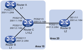
As shown in Figure 1, Router A, Router B, Router C and Router D, all enabled with IPv6, reside in the same autonomous system. Configure IPv6 IS-IS on the routers to make them reachable to each other.
Router A and Router B are Level-1 routers, Router D is a Level-2 router, and Router C is a Level-1-2 router. Router A, Router B, and Router C belong to area 10, and Router D is in area 20.
Configuration procedure
1. Configure IPv6 addresses for interfaces. (Details not shown)
2. Configure IPv6 IS-IS:
# Configure Router A.
<RouterA> system-view
[RouterA] isis 1
[RouterA-isis-1] is-level level-1
[RouterA-isis-1] network-entity 10.0000.0000.0001.00
[RouterA-isis-1] ipv6 enable
[RouterA-isis-1] quit
[RouterA] interface POS 2/1/1
[RouterA-POS2/1/1] isis ipv6 enable 1
[RouterA-POS2/1/1] quit
# Configure Router B.
<RouterB> system-view
[RouterB] isis 1
[RouterB-isis-1] is-level level-1
[RouterB-isis-1] network-entity 10.0000.0000.0002.00
[RouterB-isis-1] ipv6 enable
[RouterB-isis-1] quit
[RouterB] interface POS 2/1/1
[RouterB-POS2/1/1] isis ipv6 enable 1
[RouterB-POS2/1/1] quit
# Configure Router C.
<RouterC> system-view
[RouterC] isis 1
[RouterC-isis-1] network-entity 10.0000.0000.0003.00
[RouterC-isis-1] ipv6 enable
[RouterC-isis-1] quit
[RouterC] interface POS 2/1/1
[RouterC-POS2/1/1] isis ipv6 enable 1
[RouterC-POS2/1/1] quit
[RouterC] interface POS 2/1/2
[RouterC-POS2/1/2] isis ipv6 enable 1
[RouterC-POS2/1/2] quit
[RouterC] interface POS 2/1/3
[RouterC-POS2/1/3] isis ipv6 enable 1
[RouterC-POS2/1/3] quit
# Configure Router D.
<RouterD> system-view
[RouterD] isis 1
[RouterD-isis-1] is-level level-2
[RouterD-isis-1] network-entity 20.0000.0000.0004.00
[RouterD-isis-1] ipv6 enable
[RouterD-isis-1] quit
[RouterD] interface POS 2/1/1
[RouterD-POS2/1/1] isis ipv6 enable 1
[RouterD-POS2/1/1] quit
[RouterD] interface GigabitEthernet 1/1/1
[RouterD-GigabitEthernet1/1/1] isis ipv6 enable 1
[RouterD-GigabitEthernet1/1/1] quit
3. Verify the configuration:
# Display the IPv6 IS-IS routing table of Router A.
[RouterA] display isis route ipv6
Route information for ISIS(1)
-----------------------------
ISIS(1) IPv6 Level-1 Forwarding Table
-------------------------------------
Destination: :: PrefixLen: 0
Flag : R/-/- Cost : 10
Next Hop : FE80::200:FF:FE0F:4 Interface: S2/1/1
Destination: 2001:1:: PrefixLen: 64
Flag : D/L/- Cost : 10
Next Hop : Direct Interface: S2/1/1
Destination: 2001:2:: PrefixLen: 64
Flag : R/-/- Cost : 20
Next Hop : FE80::200:FF:FE0F:4 Interface: S2/1/1
Destination: 2001:3:: PrefixLen: 64
Flag : R/-/- Cost : 20
Next Hop : FE80::200:FF:FE0F:4 Interface: S2/1/1
Flags: D-Direct, R-Added to RM, L-Advertised in LSPs, U-Up/Down Bit Set
# Display the IPv6 IS-IS routing table of Router B.
[RouterB] display isis route ipv6
Route information for ISIS(1)
-----------------------------
ISIS(1) IPv6 Level-1 Forwarding Table
-------------------------------------
Destination: :: PrefixLen: 0
Flag : R/-/- Cost : 10
Next Hop : FE80::200:FF:FE0F:4 Interface: S2/1/1
Destination: 2001:1:: PrefixLen: 64
Flag : D/L/- Cost : 10
Next Hop : FE80::200:FF:FE0F:4 Interface: S2/1/1
Destination: 2001:2:: PrefixLen: 64
Flag : R/-/- Cost : 20
Next Hop : Direct Interface: S2/1/1
Destination: 2001:3:: PrefixLen: 64
Flag : R/-/- Cost : 20
Next Hop : FE80::200:FF:FE0F:4 Interface: S2/1/1
Flags: D-Direct, R-Added to RM, L-Advertised in LSPs, U-Up/Down Bit Set
# Display the IPv6 IS-IS routing table of Router C.
[RouterC] display isis route ipv6
Route information for ISIS(1)
-----------------------------
ISIS(1) IPv6 Level-1 Forwarding Table
-------------------------------------
Destination: 2001:1:: PrefixLen: 64
Flag : D/L/- Cost : 10
Next Hop : Direct Interface: S2/1/2
Destination: 2001:2:: PrefixLen: 64
Flag : D/L/- Cost : 10
Next Hop : Direct Interface: S2/1/1
Destination: 2001:3:: PrefixLen: 64
Flag : D/L/- Cost : 10
Next Hop : Direct Interface: S2/1/3
Flags: D-Direct, R-Added to RM, L-Advertised in LSPs, U-Up/Down Bit Set
ISIS(1) IPv6 Level-2 Forwarding Table
-------------------------------------
Destination: 2001:1:: PrefixLen: 64
Flag : D/L/- Cost : 10
Next Hop : Direct Interface: S2/1/2
Destination: 2001:2:: PrefixLen: 64
Flag : D/L/- Cost : 10
Next Hop : Direct Interface: S2/1/1
Destination: 2001:3:: PrefixLen: 64
Flag : D/L/- Cost : 10
Next Hop : Direct Interface: S2/1/3
Destination: 2001:4::1 PrefixLen: 128
Flag : R/-/- Cost : 10
Next Hop : FE80::20F:E2FF:FE3E:FA3D Interface: S2/1/3
Flags: D-Direct, R-Added to RM, L-Advertised in LSPs, U-Up/Down Bit Set
# Display the IPv6 IS-IS routing table of Router D.
[RouterD] display isis route ipv6
Route information for ISIS(1)
-----------------------------
ISIS(1) IPv6 Level-2 Forwarding Table
-------------------------------------
Destination: 2001:1:: PrefixLen: 64
Flag : R/-/- Cost : 20
Next Hop : FE80::200:FF:FE0F:4 Interface: S2/1/1
Destination: 2001:2:: PrefixLen: 64
Flag : R/-/- Cost : 20
Next Hop : FE80::200:FF:FE0F:4 Interface: S2/1/1
Destination: 2001:3:: PrefixLen: 64
Flag : D/L/- Cost : 10
Next Hop : Direct Interface: S2/1/1
Destination: 2001:4::1 PrefixLen: 128
Flag : D/L/- Cost : 0
Next Hop : Direct Interface: GE1/1/1
Flags: D-Direct, R-Added to RM, L-Advertised in LSPs, U-Up/Down Bit Set
Configuring BFD for IS-IS
Network requirements
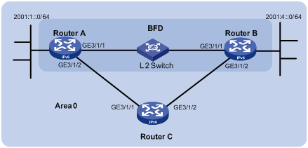
· As shown in Figure 2, configure IPv6 IS-IS on Router A, Router B and Router C and configure BFD over the link Router A<—>L2 Switch<—>Router B.
· After the link between Router B and the Layer-2 switch fails, BFD can quickly detect the failure and notify IPv6 IS-IS of the failure. Then Router A and Router B communicate through Router C.
|
Device |
Interface |
IPv6 address |
Device |
Interface |
IPv6 address |
|
Router A |
GE3/1/1 |
2001::1/64 |
Router B |
GE3/1/1 |
2001::2/64 |
|
|
GE3/1/2 |
2001:2::1/64 |
|
GE3/1/2 |
2001:3::2/64 |
|
Router C |
GE3/1/1 |
2001:2::2/64 |
|
|
|
|
|
GE3/1/2 |
2001:3::1/64 |
|
|
|
Configuration procedure
1. Configure IP addresses for interfaces. (Details not shown)
2. Configure IPv6 IS-IS:
# Configure Router A.
<RouterA> system-view
[RouterA] ipv6
[RouterA] isis 1
[RouterA-isis-1] is-level level-1
[RouterA-isis-1] network-entity 10.0000.0000.0001.00
[RouterA-isis-1] ipv6 enable
[RouterA-isis-1] quit
[RouterA] interface GigabitEthernet 3/1/1
[RouterA-GigabitEthernet3/1/1] isis ipv6 enable 1
[RouterA-GigabitEthernet3/1/1] quit
[RouterA] interface GigabitEthernet 3/1/2
[RouterA-GigabitEthernet3/1/2] isis ipv6 enable 1
[RouterA-GigabitEthernet3/1/2] quit
# Configure Router B.
<RouterB> system-view
[RouterA] ipv6
[RouterB] isis 1
[RouterB-isis-1] is-level level-1
[RouterB-isis-1] network-entity 10.0000.0000.0002.00
[RouterB-isis-1] ipv6 enable
[RouterB-isis-1] quit
[RouterB] interface GigabitEthernet 3/1/1
[RouterB-GigabitEthernet3/1/1] isis ipv6 enable 1
[RouterB-GigabitEthernet3/1/1] quit
[RouterB] interface GigabitEthernet 3/1/2
[RouterB-GigabitEthernet3/1/2] isis ipv6 enable 1
[RouterB-GigabitEthernet3/1/2] quit
# Configure Router C.
<RouterC> system-view
[RouterA] ipv6
[RouterC] isis 1
[RouterC-isis-1] network-entity 10.0000.0000.0003.00
[RouterC-isis-1] ipv6 enable
[RouterC-isis-1] quit
[RouterC] interface GigabitEthernet 3/1/1
[RouterC-GigabitEthernet3/1/1] isis ipv6 enable 1
[RouterC-GigabitEthernet3/1/1] quit
[RouterC] interface GigabitEthernet 3/1/2
[RouterC-GigabitEthernet3/1/2] isis ipv6 enable 1
[RouterC-GigabitEthernet3/1/2] quit
3. Configure BFD functions:
# Enable BFD on Router A and configure BFD parameters.
[RouterA] bfd session init-mode active
[RouterA] interface GigabitEthernet 3/1/1
[RouterA-GigabitEthernet3/1/1] isis ipv6 bfd enable
[RouterA-GigabitEthernet3/1/1] bfd min-transmit-interval 500
[RouterA-GigabitEthernet3/1/1] bfd min-receive-interval 500
[RouterA-GigabitEthernet3/1/1] bfd detect-multiplier 7
[RouterA-GigabitEthernet3/1/1] return
# Enable BFD on Router B and configure BFD parameters.
[RouterB] bfd session init-mode active
[RouterB] interface GigabitEthernet 3/1/1
[RouterB-GigabitEthernet3/1/1] isis ipv6 bfd enable
[RouterB-GigabitEthernet3/1/1] bfd min-transmit-interval 500
[RouterB-GigabitEthernet3/1/1] bfd min-receive-interval 500
[RouterB-GigabitEthernet3/1/1] bfd detect-multiplier 6
4. Verify configuration:
The following operations are performed on Router A. Operations for Router B are similar. (Details not shown)
# Display the BFD information of Router A.
<RouterA> display bfd session
Total Session Num: 1 Init Mode: Active
IPv6 Session Working Under Ctrl Mode:
Local Discr: 1441 Remote Discr: 1450
Source IP: FE80::20F:FF:FE00:1202 (link-local address of GigabitEthernet3/1/1 on Router A)
Destination IP: FE80::20F:FF:FE00:1200 (link-local address of GigabitEthernet3/1/1 on Router B)
Session State: Up Interface: GE3/1/1
Hold Time: /
# Display route 2001:4::0/64 on Router A, and you can see that Router A and Router B communicate through the Layer 2 switch.
<RouterA> display ipv6 routing-table 2001:4::0 64 verbose
Routing Table :
Summary Count : 2
Destination : 2001:4::0 PrefixLength : 64
NextHop : 2001::2 Preference : 15
RelayNextHop : :: Tag : 0H
Neighbor : :: ProcessID : 0
Interface : GigabitEthernet3/1/1 Protocol : ISISv6
State : Active Adv Cost : 20
Tunnel ID : 0x0 Label : NULL
Age : 4538sec
Destination : 2001:4::0 PrefixLength : 64
NextHop : 2001:2::2 Preference : 15
RelayNextHop : :: Tag : 0H
Neighbor : :: ProcessID : 0
Interface : GigabitEthernet3/1/2 Protocol : ISISv6
State : Invalid Adv Cost : 30
Tunnel ID : 0x0 Label : NULL
Age : 4515sec
# Enable BFD debugging on Router A.
<RouterA> debugging bfd scm
<RouterA> debugging bfd event
<RouterA> debugging isis event bfd
<RouterA> terminal debugging
# When the link between Router B and the Layer-2 switch fails, BFD can quickly detect the failure.
#Aug 8 14:54:05:362 2009 RouterA IFNET/4/INTERFACE UPDOWN:
Trap 1.3.6.1.6.3.1.1.5.3<linkDown>: Interface 983041 is Down, ifAdminStatus is 1, ifOperStatus is 2
#Aug 8 14:54:05:363 2009 RouterA ISIS/4/ADJ_CHANGE:TrapID(1.3.6.1.2.1.138.0.17<isisAdjacencyChange>), ISIS Level-2 Adjencency IN Circuit-983041 State Change.
#Aug 8 14:54:05:364 2008 RouterA ISIS/4/ADJ_CHANGE:TrapID(1.3.6.1.2.1.138.0.17<isisAdjacencyChange>), ISIS Level-1 Adjencency IN Circuit-983041 State Change.
%Aug 8 14:54:05:365 2009 RouterA IFNET/4/LINK UPDOWN: GigabitEthernet3/1/1: link status is DOWN
%Aug 8 14:54:05:366 2008 RouterA IFNET/4/UPDOWN: Line protocol on the interface GigabitEthernet3/1/1 is DOWN
%Aug 8 14:54:05:367 2009 RouterA ISIS/4/ADJLOG:ISIS-1-ADJCHANGE: Adjacency To 0000.0000.0002 (GE3/1/1) DOWN, Level-2 Circuit Down.
%Aug 8 14:54:05:367 2009 RouterA ISIS/4/ADJLOG:ISIS-1-ADJCHANGE: Adjacency To 0000.0000.0002 (GE3/1/1) DOWN, Level-2 Adjacency clear.
%Aug 8 14:54:05:368 2009 RouterA ISIS/4/ADJLOG:ISIS-1-ADJCHANGE: Adjacency To 0000.0000.0002 (GE3/1/1) DOWN, Level-1 Circuit Down.
%Aug 8 14:54:05:369 2009 RouterA ISIS/4/ADJLOG:ISIS-1-ADJCHANGE: Adjacency To 0000.0000.0002 (GE3/1/1) DOWN, Level-1 Adjacency clear.
*Aug 8 14:54:05:369 2009 RouterA ISIS/6/ISIS: ISIS-1-BFD: Recieve BFD session down . Type 0. DstIPAddr: FE80::20F:FF:FE00:1200 , SrcIPAddr: FE80::20F:FF:FE00:1202
*Aug 8 14:54:05:370 2009 RouterA ISIS/6/ISIS: ISIS-1-BFD: Success to send msg. Msg type 1 delete session. IfPhyIndex: 5 ,DstIPAddr: FE80::20F:FF:FE00:1200 , SrcIPAddr: FE80::20F:FF:FE00:1202 . NeighborType: Level-1.
# Display the BFD information of Router A. You can see that Router A has removed its neighbor relationship with Router B and therefore no information is output.
<RouterA> display bfd session
# Display route 2001:4::0/64 on Router A, and you can see that Router A and Router B communicate through Router C.
<RouterA> display ipv6 routing-table 2001:4::0 64 verbose
Routing Table :
Summary Count : 1
Destination : 2001:4::0 PrefixLength : 64
NextHop : 2001:2::2 Preference : 15
RelayNextHop : :: Tag : 0H
Neighbor : :: ProcessID : 0
Interface : GigabitEthernet3/1/2 Protocol : ISISv6
State : Invalid Adv Cost : 30
Tunnel ID : 0x0 Label : NULL
Age : 4610sec