- Table of Contents
-
- 06-Layer 3—IP Routing Configuration Guide
- 00-Preface
- 01-Basic IP routing configuration
- 02-Static routing configuration
- 03-RIP configuration
- 04-OSPF configuration
- 05-IS-IS configuration
- 06-EIGRP configuration
- 07-BGP configuration
- 08-Policy-based routing configuration
- 09-IPv6 static routing configuration
- 10-RIPng configuration
- 11-OSPFv3 configuration
- 12-IPv6 policy-based routing configuration
- 13-Routing policy configuration
- 14-DCN configuration
- Related Documents
-
| Title | Size | Download |
|---|---|---|
| 04-OSPF configuration | 2.25 MB |
Area-based OSPF network partition
OSPF neighbor flapping suppression
Restrictions and guidelines: OSPF configuration
Configuring basic OSPF functions
Configuring OSPF network types
Restrictions and guidelines for configuring OSPF network types
Configuring the broadcast network type for an interface
Configuring the NBMA network type for an interface
Configuring the P2MP network type for an interface
Configuring the P2P network type for an interface
Configuring OSPF route control
Configuring OSPF inter-area route summarization
Configuring redistributed route summarization
Configuring received OSPF route filtering
Configuring Type-3 LSA filtering
Setting an OSPF cost for an interface
Changing the link cost of a Layer 3 aggregate interface when its bandwidth falls below the threshold
Enabling OSPF to advertise the maximum link cost to neighbors
Setting the maximum number of ECMP routes
Configuring discard routes for summary networks
Redistributing routes from another routing protocol
Adjusting the route tagging mechanism to prevent routing loops
Redistributing a default route
Advertising OSPF link state information to BGP
Configuring OSPF to advertise network performance parameters
About OSPF network performance parameters
Advertising link delay information
Advertising link bandwidth information
Configuring OSPF packet timers
Setting LSA transmission delay
Setting SPF calculation interval
Setting the LSA reception interval
Setting the LSA update interval
Setting OSPF exit overflow interval
Configuring OSPF packet parameters
Disabling interfaces from receiving and sending OSPF packets
Adding the interface MTU into DD packets
Setting the DSCP value for outgoing OSPF packets
Setting the maximum length of OSPF packets that can be sent by an interface
Enabling OSPF to limit the LSU packet transmission rate
Controlling LSA generation, advertisement, and reception
Setting the maximum number of external LSAs in LSDB
Filtering outbound LSAs on an interface
Filtering LSAs for the specified neighbor
Configuring update suppression
Accelerating OSPF convergence speed
Configuring prefix suppression
Configuring prefix prioritization
Configuring advanced OSPF features
Enabling compatibility with RFC 1583
Configuring OSPF dynamic host name mappings
Configuring OSPF neighbor flapping suppression
Configuring the virtual system feature
Configuring bidirectional control detection
Configuring single-hop echo detection
Enabling OSPF to adjust the interface cost according to the BFD session state
Suppressing interface cost adjustment according to the BFD session state upon BFD session flapping
Restrictions and guidelines for OSPF FRR
Configuring OSPF remote LFA FRR
Configuring OSPF FRR to use a backup next hop specified in a routing policy
Setting the priority for FRR backup path selection policies
Configuring BFD control packet mode for OSPF FRR
Configuring BFD echo packet mode for OSPF FRR
Enabling OSPF to adjust the interface cost according to the link quality
Configuring OSPF authentication
About OSPF area and interface authentication
Configuring OSPF area authentication
Configuring OSPF interface authentication
Restrictions and guidelines for GTSM
Configuring GTSM in OSPF area view
Configuring GTSM in interface view
Configuring OSPF multi-area adjacency
Enabling OSPF on a multi-area adjacency interface
Setting the OSPF cost on a multi-area adjacency interface
Setting the authentication mode and key on a multi-area adjacency interface
Configuring fast convergence for a multi-area adjacent interface
Enabling OSPF to adjust the cost of a multi-area adjacency interface according to the link quality
Enabling a multi-area adjacency interface to add its MTU into DD packets
Setting the maximum length of OSPF packets that can be sent by a multi-area adjacency interface
Configuring OSPF logging and SNMP notifications
Logging neighbor state changes
Configuring the OSPF logging feature
Configuring OSPF network management
Setting the maximum number of OSPF neighbor relationship troubleshooting entries
Display and maintenance commands for OSPF
Example: Configuring basic OSPF
Example: Configuring OSPF route redistribution
Example: Configuring OSPF route summarization
Example: Configuring OSPF stub area
Example: Configuring OSPF NSSA area
Example: Configuring OSPF DR election
Example: Configuring OSPF virtual link
Example: Configuring BFD for OSPF
Example: Configuring an OSPF stub router
Troubleshooting OSPF configuration
No OSPF neighbor relationship established
Configuring OSPF
About OSPF
Open Shortest Path First (OSPF) is a link state-based interior gateway protocol (IGP) developed by the OSPF working group of the IETF. OSPF version 2 is used for IPv4. OSPF refers to OSPFv2 throughout this chapter.
OSPF features
Before OSPF was developed, Routing Information Protocol (RIP) was widely used. Due to its slow convergence, susceptibility to routing loops, and poor expansion capabilities, RIP, a distance-vector IGP, was gradually replaced by OSPF.
Typical IGPs include RIP, OSPF, and IS-IS. The differences between them are shown in Table 1.
Table 1 Differences between IGPs
|
Item |
RIP |
OSPF |
IS-IS |
|
Protocol type |
IP Layer protocol |
IP layer protocol |
Link layer protocol |
|
Application scope |
Suitable for small networks. |
Suitable for medium-sized networks |
Suitable for large networks. |
|
Routing algorithm |
Uses the distance-vector algorithm. |
Uses the Shortest Path First (SPF) algorithm. OSPF advertises the network topology through Link State Advertisements (LSAs), creates a Shortest Path Tree (SPT) based on that topology, calculates the shortest path to all destinations on the network, and exchanges routing information. |
Uses the Shortest Path First (SPF) algorithm. IS-IS creates a SPT based on the network topology and calculates the shortest paths to all destinations on the network. |
|
Convergence speed |
Low. |
High. |
High. |
|
Scalability |
Not scalable. |
Enhances the scalability of the OSPF network by splitting an AS into areas. |
Enhances the scalability of the IS-IS network by a 2-level hierarchy of routers. |
OSPF has the following features:
· Wide scope—Supports multiple network sizes and several hundred routers in an OSPF routing domain.
· Fast convergence—Advertises routing updates instantly upon network topology changes.
· Loop free—Computes routes with the SPF algorithm to avoid routing loops.
· Area-based network partition—Splits an AS into multiple areas to facilitate management. This feature reduces the LSDB size on routers to save memory and CPU resources, and reduces route updates transmitted between areas to save bandwidth.
· ECMP routing—Supports multiple equal-cost routes to a destination.
· Routing hierarchy—Supports a 4-level routing hierarchy that prioritizes routes into intra-area, inter-area, external Type-1, and external Type-2 routes.
· Authentication—Supports area- and interface-based packet authentication to ensure secure packet exchange.
· Support for multicasting—Multicasts protocol packets on some types of links to avoid impacting other devices.
Router ID
A router ID uniquely identifies a router in an AS. For a router to run OSPF, it must have a router ID. You can choose to manually specify a router ID, automatically obtain a router ID, or use the global router ID for an OSPF process.
Manual configuration
When you create an OSPF process, you can manually specify a router ID. To make sure the router ID is unique in the AS, you can specify the IP address of an interface on the router as the router ID.
Automatic configuration
When you create an OSPF process, you can enable the OSPF process to automatically obtain a router ID. The OSPF process obtains a router ID in the following ways:
· During the startup of the OSPF process, the primary IPv4 address of the first interface that runs the process is specified as the router ID.
· During the reboot of the router, the primary IPv4 address of the first interface that runs the process is specified as the router ID.
· During the restart of the OSPF process, the highest primary IPv4 address of the loopback interface that runs the process is specified as the router ID. If no loopback address is available, the highest primary IPv4 address of the interface that runs the process is used, regardless of the interface state (up or down).
Using the global router ID
If you do not specify a router ID when creating an OSPF process, the global router ID is used. As a best practice, manually specify a router ID or enable the OSPF process to automatically obtain a router ID when you create the OSPF process.
Area-based OSPF network partition
In large OSPF routing domains, SPF route computations consume too many storage and CPU resources, and enormous OSPF packets generated for route synchronization occupy excessive bandwidth.
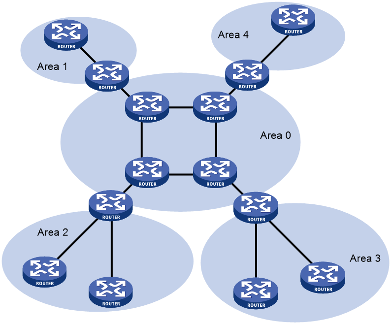
To resolve these issues, OSPF splits an AS into multiple areas. Each area is identified by an area ID. The boundaries between areas are routers rather than links. A network segment (or a link) can only reside in one area as shown in Figure 1.
You can configure route summarization on ABRs to reduce the number of LSAs advertised to other areas and minimize the effect of topology changes.
Figure 1 Area-based OSPF network partition
OSPF areas
OSPF supports the following types of areas:
· Standard area.
· Backbone area.
· Stub area.
· Totally stub area.
· Not-so-stubby area (NSSA).
· Totally NSSA area.
Standard area
A standard area is the default OSPF area, which transmits intra-area routes, inter-area routes, and external routes.
Backbone area
Each AS has a backbone area that distributes routing information between non-backbone areas. Routing information between non-backbone areas must be forwarded by the backbone area. OSPF has the following requirements:
· All non-backbone areas must maintain connectivity to the backbone area.
· The backbone area must maintain connectivity within itself.
In practice, these requirements might not be met due to lack of physical links. OSPF virtual links can solve this issue.
Stub area and totally stub area
A stub area does not distribute Type-5 LSAs to reduce the routing table size and LSAs advertised within the area. The ABR of the stub area advertises a default route in a Type-3 LSA so that the routers in the area can reach external networks through the default route.
To further reduce the routing table size and advertised LSAs, you can configure the stub area as a totally stub area. The ABR of a totally stub area does not advertise inter-area routes or external routes. It advertises a default route in a Type-3 LSA so that the routers in the area can reach external networks through the default route.
NSSA area and totally NSSA area
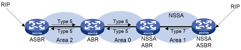
An NSSA area does not import AS external LSAs (Type-5 LSAs) but can import Type-7 LSAs generated by the NSSA ASBR. The NSSA ABR translates Type-7 LSAs into Type-5 LSAs and advertises the Type-5 LSAs to other areas.
As shown in Figure 2, the OSPF AS contains Area 1, Area 2, and Area 0. The other two ASs run RIP. Area 1 is an NSSA area where the ASBR redistributes RIP routes in Type-7 LSAs into Area 1. Upon receiving the Type-7 LSAs, the NSSA ABR translates them to Type-5 LSAs, and advertises the Type-5 LSAs to Area 0.
The ASBR of Area 2 redistributes RIP routes in Type-5 LSAs into the OSPF routing domain. However, Area 1 does not receive Type-5 LSAs because it is an NSSA area.

Router types
As shown in Figure 3, OSPF routers are classified into different types, including internal routers, ABRs, backbone routers, and ASBRs.
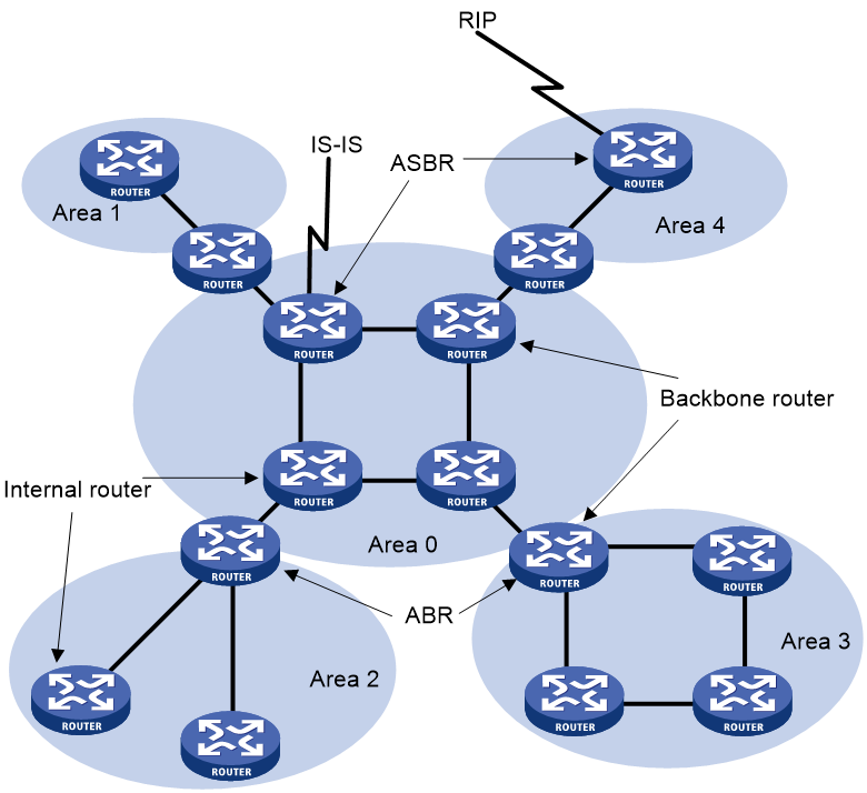
Internal router
All interfaces on an internal router belong to one OSPF area.
ABR
An ABR belongs to more than two areas, one of which must be the backbone area. ABR connects the backbone area to a non-backbone area. An ABR and the backbone area can be connected through a physical or logical link.
Backbone router
No less than one interface of a backbone router must reside in the backbone area. All ABRs and internal routers in Area 0 are backbone routers.
ASBR
An ASBR exchanges routing information with another AS. An ASBR might not reside on the border of the AS. It can be an internal router or an ABR.
OSPF packet types
OSPF packets are carried directly over IP. The protocol number is 89.
OSPF uses the following packet types:
· Hello—Periodically sent to find and maintain neighbors, containing timer values, information about the DR, BDR, and known neighbors.
· Database description (DD)—Describes the digest of each LSA in the LSDB, exchanged between two routers for data synchronization.
· Link state request (LSR)—Requests needed LSAs from a neighbor. After exchanging the DD packets, the two routers know which LSAs of the neighbor are missing from their LSDBs. They then exchange LSR packets requesting the missing LSAs. LSR packets contain the digest of the missing LSAs.
· Link state update (LSU)—Transmits the requested LSAs to the neighbor.
· Link state acknowledgment (LSAck)—Acknowledges received LSU packets. It contains the headers of received LSAs (an LSAck packet can acknowledge multiple LSAs).
OSPF packet formats
OSPF packet header
OSPF packets of the five types share the same 24-byte header format. The OSPF packet header format is as shown in Figure 4.
Figure 4 OSPF packet header format
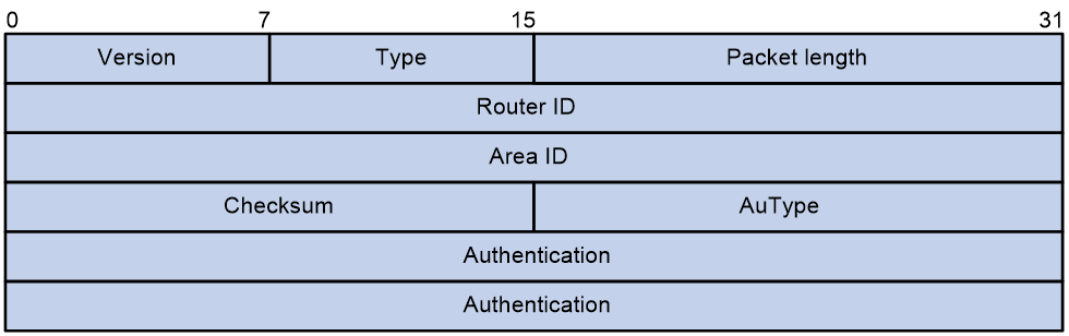
OSPF packet header fields are as shown in Table 2.
Table 2 OSPF packet header fields
|
Field |
Length |
Description |
|
Version |
8-bit |
Version number of the OSPF protocol. The value of this field is 2 for OSPFv2. |
|
Type |
8-bit |
Type of the OSPF packet. Options include: · 1—Hello packet. · 2—DD packet. · 3—LSR packet. · 4—LSU packet. · 5—LSAck packet. |
|
Packet length |
16-bit |
Length of the OSPF packet, including the header, in bytes. |
|
Router ID |
32-bit |
Router ID of the device that sends the packet. |
|
Area ID |
32-bit |
Area to which the device sending the packet belongs. |
|
Checksum |
16-bit |
Checksum for the entire packet, excluding the authentication field. |
|
AuTpye |
16-bit |
Authentication type. Options include: · 0—Not authenticated. · 1—Simple authentication. · 2—MD5 authentication. |
|
Authentication |
64-bit |
Value of this field varies by authentication type: · 0—This field is not defined. · 1—This field contains password information. · 2—This field contains information including the key ID, MD5 authentication data length, and serial number. |
Hello packet
Hello packets establish and maintain adjacency relationships. The format of a hello packet is shown in Figure 5.
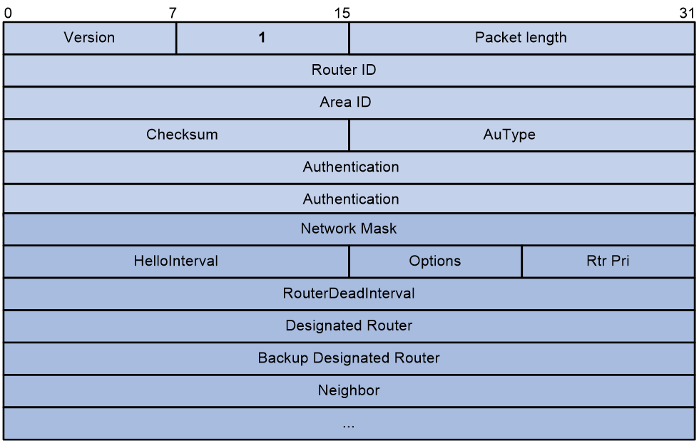
Fields in a hello packet are as shown in Table 3.
Table 3 Fields in a hello packet
|
Field |
Length |
Description |
|
Network Mask |
32-bit |
The mask of the network where the interface that transmits hello packets is located. |
|
HelloInterval |
16-bit |
Transmitting interval for the hello packet. |
|
Options |
8-bit |
The options of the hello packet: · DC—On-demand link · N/P—Processing method for Type-7 LSAs. · MC—Whether to forward multicast packets. · E—Whether flooding of AS-External LSAs is permitted. ¡ 1—Flooding of AS-External LSAs is permitted. ¡ 0—Flooding of AS-External LSAs is not permitted. |
|
Rtr Pri |
8-bit |
DR priority. The default value is 1. |
|
RouterDeadInterval |
32-bit |
Neighbor dead interval. If a hello packet from the neighbor is not received within the interval, the neighbor is considered unreachable. |
|
Designated Router |
32-bit |
DR interface address. |
|
Backup Designated Router |
32-bit |
BDR interface address. |
|
Neighbor |
32-bit |
Neighbor, identified by Router ID. |
The destination address type of hello packets sent by the device, the transmitting interval type, and the interval default vary by network type, as shown in Table 4.
Table 4 Hello packets sent on different types of networks
|
Network type |
Destination address type for transmitting hello packets |
Transmiting interval type |
Default value for the transmiting interval |
|
Broadcast |
Multicast address |
HelloInterval |
By default, the hello packet transmitting interval of an interface is 10 seconds. |
|
NBMA |
Unicast address |
· PollInterval—For polling hello packets sent to neighbors in Down state. · HelloInterval—For hello packets in other cases. |
By default, the hello packet transmitting interval of an interface is 30 seconds. By default, the polling hello packet transmitting interval of an interface is 30 seconds. |
|
P2P |
Multicast address |
HelloInterval |
By default, the hello packet transmitting interval of an interface is 10 seconds. |
|
P2MP |
Multicast address |
HelloInterval |
By default, the hello packet transmitting interval of an interface is 30 seconds. |
DD packet
The DD packet format is as shown in Figure 6.
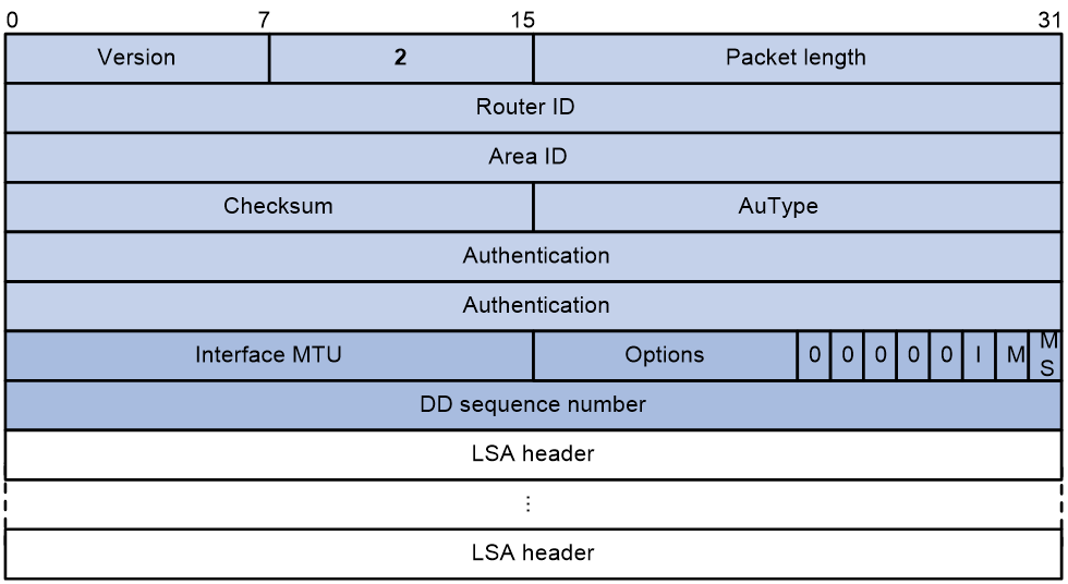
Fields in a DD packet are as shown in Table 5.
Table 5 Fields in a DD packet
|
Field |
Length |
Description |
|
Interface MTU |
16-bit |
Maximum length for IP packets that the interface can transmit without fragmentation. |
|
Options |
8-bit |
Options in a Hello packet, including: · DC: On-demand link. · N/P: Processing method for Type-7 LSA. · MC: Whether IP multicast packets can be forwarded. · E: Whether AS-External LSA flooding is allowed. When the E flag is set to 1, it indicates AS-External LS flooding is allowed. When the E flag is set to 0, it indicates AS-External LS flooding is not allowed. |
|
I |
1-bit |
Init bit. The value of 1 indicates that the transmitted packet is the first DD packet. If it is not the first DD packet, the value is set to 0. |
|
M |
1-bit |
More bit. The value of 1 indicates that the transmitted packet is not the final DD packet. If it is the final DD packet, this field is set to 0. |
|
MS |
1-bit |
Master/Slave bit. This field is set to 1 only in the DD packets transmitted by the master. |
|
DD sequence number |
32-bit |
DD packet sequence number, used to sort DD packets. Both master and slave devices use the sequence number to ensure the reliability and integrity of DD packets during transmission. |
|
LSA header |
- |
LSA header information in the DD packet. |
LSR packet
LSR packets request the necessary LSAs. The format of an LSR packet is as shown in Figure 7.
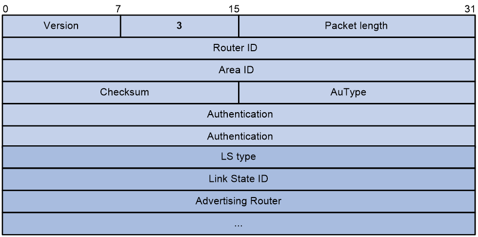
Fields in an LSR packet are as shown in Table 6.
Table 6 Fields in an LSR packet
|
Field |
Length |
Description |
|
LS type |
32-bit |
type of the LSA. An LSA is uniquely identified by the LS type, Link State ID, and Advertising Router. When two LSAs have the same LS type, Link State ID, and Advertising Router, the device determines the recency of the LSAs based on the LS sequence number, LS checksum, and LS age. |
|
Link State ID |
32-bit |
Link state ID. |
|
Advertising Router |
32-bit |
Router ID of the device that generated this LSA. |
LSU packet
LSU packets transmit the required LSAs. The format of an LSU packet is as shown in Figure 8.
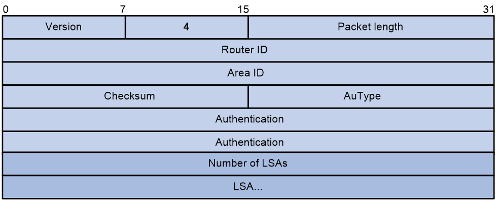
Fields in an LSU packet are as shown in Table 7.
Table 7 Fields in an LSU packet
|
Field |
Length |
Description |
|
Number of LSAs |
32-bit |
Number of LSAs in the LSU packet. |
LSAck packet
LSAck packets validate the received LSAs. The format of an LSAck packet is as shown in Figure 9.
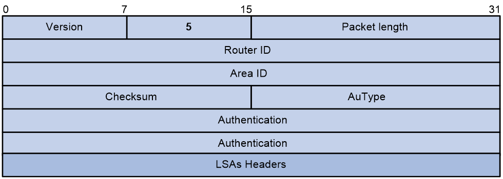
Fields in an LSAck packet are as shown in Table 8.
Table 8 Fields in an LSAck packet
|
Field |
Length |
Description |
|
LSAs Headers |
Vary by head length of the LSA that requires acknowledgement. |
Header information of each acknowledged LSA. |
OSPF LSA types
OSPF advertises routing information in Link State Advertisements (LSAs). The following LSAs are commonly used:
· Router LSA—Type-1 LSA, originated by all routers and flooded throughout a single area only. This LSA describes the collected states of the router's interfaces to an area.
· Network LSA—Type-2 LSA, originated for broadcast and NBMA networks by the designated router, and flooded throughout a single area only. This LSA contains the list of routers connected to the network.
· Network Summary LSA—Type-3 LSA, originated by Area Border Routers (ABRs), and flooded throughout the LSA's associated area. Each summary-LSA describes a route to a destination outside the area, yet still inside the AS (an inter-area route).
· ASBR Summary LSA—Type-4 LSA, originated by ABRs and flooded throughout the LSA's associated area. Type 4 summary-LSAs describe routes to Autonomous System Boundary Router (ASBR).
· AS External LSA—Type-5 LSA, originated by ASBRs, and flooded throughout the AS (except stub and NSSA areas). Each AS-external-LSA describes a route to another AS.
· NSSA LSA—Type-7 LSA, as defined in RFC 1587, originated by ASBRs in NSSAs and flooded throughout a single NSSA. NSSA LSAs describe routes to other ASs.
· Opaque LSA—A proposed type of LSA. Its format consists of a standard LSA header and application specific information. Opaque LSAs are used by the OSPF protocol or by some applications to distribute information into the OSPF routing domain. The opaque LSA includes Type 9, Type 10, and Type 11. The Type 9 opaque LSA is flooded into the local subnet, the Type 10 is flooded into the local area, and the Type 11 is flooded throughout the AS.
Type-1, Type-2, Type-3, Type-5, Type-7 LSAs are flooded in different areas as shown in Figure 10 and Figure 10Table 9.
Figure 10 Type-1, 2, 3, 5, 7 LSAs flooded in different types of areas
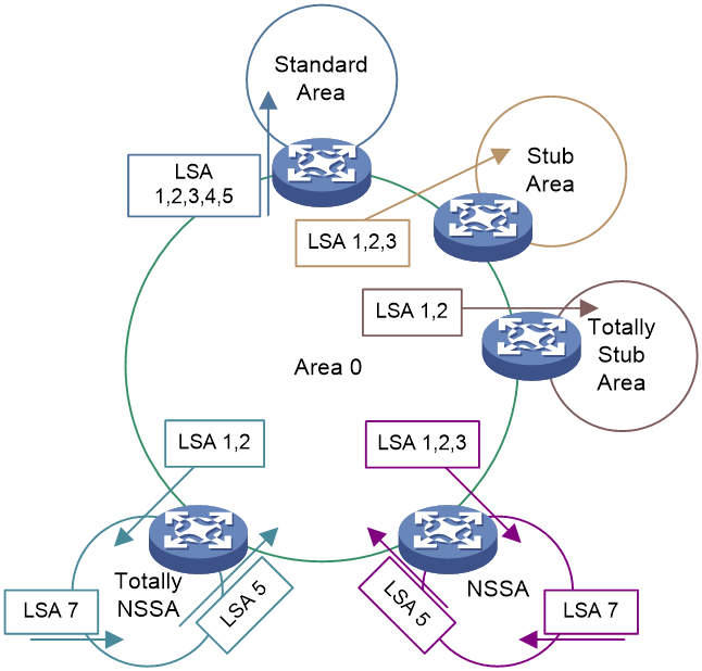
Table 9 Type-1, 2, 3, 5, 7 LSAs flooded in different types of areas
|
Area type |
Router LSA (Type-1) |
Network LSA (Type-2) |
Network Summary LSA (Type-3) |
ASBR Summary LSA (Type-4) |
AS External LSA (Type-5) |
NSSA External LSA (Type-7) |
|
Standard area and backbone area |
Supported |
Supported |
Supported |
Supported |
Supported |
Not supported |
|
Stub area |
Supported |
Supported |
Supported |
Not supported |
Not supported |
Not supported |
|
Totally stub area |
Supported |
Supported |
Support for Type-3 (which announces only the default route) is not available. |
Not supported |
Not supported |
Not supported |
|
NSSA area |
Supported |
Supported |
Supported |
Not supported |
Not supported |
Supported |
|
Totally NSSA area |
Supported |
Supported |
The system does not support Type-3, which only announces the default route. |
Not supported |
Not supported |
Supported |
OSPF LSA formats
LSA header
All OSPF LSAs share the same packet header format, as shown in Figure 11.
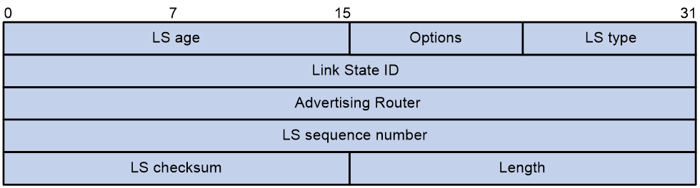
Fields in an LSA header are as shown in Table 10.
Table 10 Fields in an LSA header
|
field |
Length |
Description |
|
LS age |
16-bit |
After generation, the LSA's age, measured in seconds, continually increases during transmission over the link or while stored in the LSDB. |
|
Options |
8-bit |
Options include: · DC—On-demand link · N/P—Processing method for Type-7 LSAs. · MC—Whether to forward multicast packets. · E—Whether flooding of AS-External LSAs is permitted. ¡ 1—Flooding of AS-External LSAs is permitted. ¡ 0—Flooding of AS-External LSAs is not permitted. |
|
LS type |
8-bit |
LSA type. Options include: · 1—Router LSA. · 2—Network LSA. · 3—Network Summary LSA. · 4—ASBR Summary LSA. · 5—AS External LSA. · 7—NSSA LSA. |
|
Link State ID |
32-bit |
Link state ID, which depends on the type of LSA. For example, in a Network LSA, the link state ID is the IP address of the DR interface. |
|
Advertising Router |
32-bit |
Router ID of the device that generated this LSA. |
|
LS sequence number |
32-bit |
Sequence number of the LSA, for other devices to determine the LSA's recency when they receive it. |
|
LS checksum |
16-bit |
Checksum of the entire LSA content, excluding the LS age field. |
|
Length |
16-bit |
Total length of the LSA, including the LSA header, in bytes. |
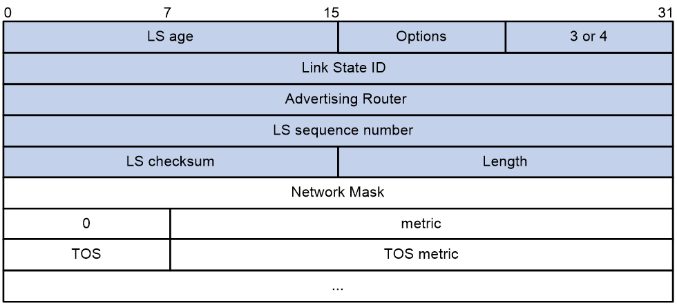
Router LSA
Each router generates Router LSAs, which describe the router's link state and cost, and advertise these LSAs within the originating area. The format of a Router LSA is as shown in Figure 12.
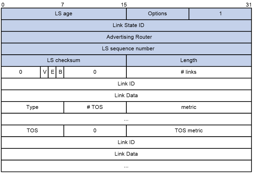
Fields in a Router LSA are as shown in Table 11.
Table 11 Fields in a Router LSA
|
field |
Length |
Description |
|
Link State ID |
32-bit |
Router ID of the device that generated the LSA. |
|
V(V is for virtual link endpoint) |
1-bit |
· 1—Device generating the LSA is a virtual link endpoint. · 0—Device generating the LSA is not a virtual link endpoint. |
|
E(E is for external) |
1-bit |
· 1—Device generating the LSA is an ASBR. · 0—Device generating the LSA is not an ASBR. |
|
B(B is for border) |
1-bit |
· 1—Device generating the LSA is an ABR. · 0—Device generating the LSA is not an ABR. |
|
# links |
16-bit |
Number of links the LSA describes. These details must include the state information for all links (interfaces) on the device within a specific area. |
|
Link ID |
32-bit |
Object to which the device connects. The link ID depends on the connection type. Options include: · 1—Router ID. · 2—IP address of the DR interface. · 3—Network segment/subnet number. · 4—Router ID of the peer in the virtual link. |
|
Link Data |
32-bit |
Link data, which depends on the connection type. Options include: · Interface index. · Subnet mask. · Device interface IP address. |
|
Type |
8-bit |
Description of the device connection status: · 1—Connect to another device in a point-to-point manner. · 2—Connect to the transmission network. · 3—Connect to the Stub network. · 4—Virtual link. |
|
# TOS |
8-bit |
The number of ToS (Type of Service) metrics. OSPF can calculate routes separately for each ToS. To differentiate routes based on ToS, you can configure interface cost for each ToS separately. |
|
metric |
16-bit |
Cost of the link. |
|
TOS |
8-bit |
Type of service. |
|
TOS metric |
16-bit |
Metric corresponding to the type of service. |
Network LSA
The DR generates Network LSAs that describe the link state for all routers in the network segment, which is advertised within the originating area. The format of a Network LSA is as shown in Figure 13.
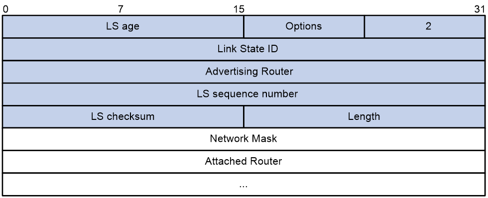
Fields in a Network LSA are as shown in Table 12.
Table 12 Fields in a Network LSA
|
Field |
Length |
Description |
|
Link State ID |
32-bit |
IP address of the DR interface. |
|
Network Mask |
32-bit |
Mask of the address used by the broadcast network or NBMA network. |
|
Attached Router |
32-bit |
Router IDs of all devices that establish adjacency with the DR in the broadcast or NBMA network, including the Router ID of the DR itself. |
Summary LSA
Summary LSAs include Network Summary (Type-3) LSAs and ASBR Summary (Type-4) LSAs.
The ABR generates Network Summary LSAs to describe the routes for a network segment within a area and advertise it to other areas.
The ABR generates ASBR Summary LSAs to describe the routes to the ASBR and advertise it to the relevant areas.
Network Summary LSAs and ASBR Summary LSAs are in the same format, as shown in Figure 14.
Fields in a Summary LSA are as shown in Table 13.
Table 13 Fields in a Summary LSA
|
Field |
Length |
Description |
|
Link State ID |
32-bit |
· For a Type-3 LSA, the field is the IP address of the network or subnet announced in the LSA. · For a Type-4 LSA, the field is the ASBR's Router ID. |
|
Network Mask |
32-bit |
· For a Type-3 LSA, this field is the mask for the announced network or subnet. · For a Type-4 LSA, the field is meaningless and is fixed at 0.0.0.0. |
|
Metric |
24-bit |
Cost of the path to the destination. |
|
TOS |
8-bit |
Type of Service (ToS). |
|
TOS metric |
24-bit |
Metric corresponding to the type of service. |
AS External LSA
The ASBR generates AS External (Type-5) LSAs to describe routes to other ASs, and advertise them to all areas except stub and NSSA areas. The format of an AS External LSA is as shown in Figure 15.
Figure 15 AS External LSA format
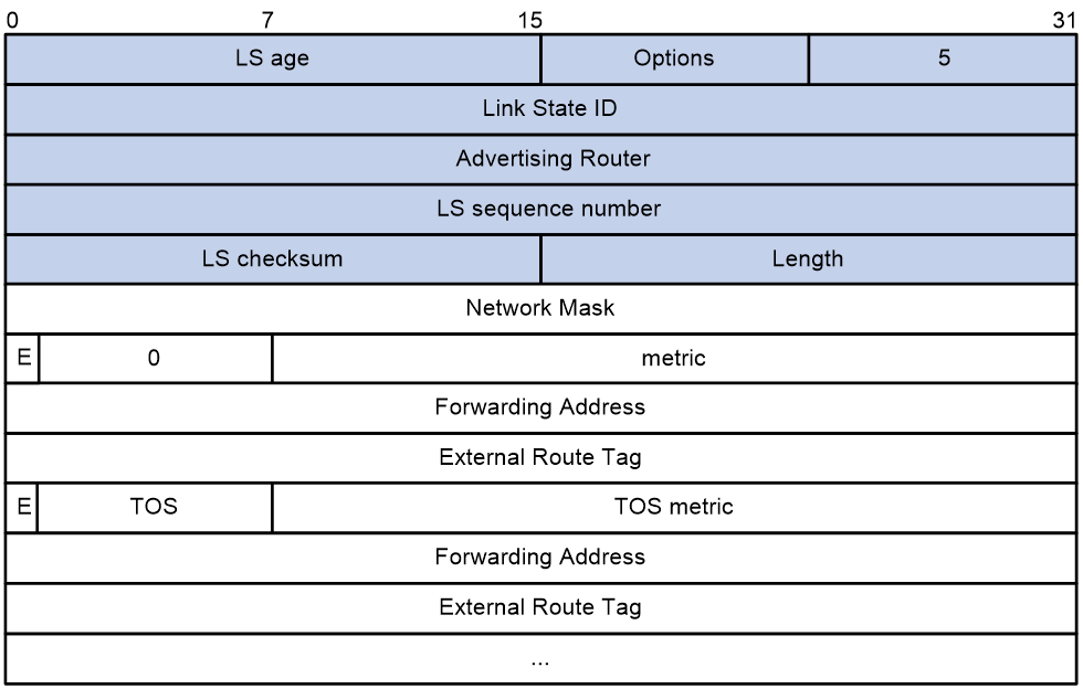
Fields in an AS External are as shown in Table 14.
Table 14 Fields in an AS External LSA
|
field |
Length |
Description |
|
Link Stat ID |
32-bit |
IP address of the network or subnet that the LSA announces. |
|
Network Mask |
32-bit |
Mask of the the network or subnet that the LSA announces. |
|
E |
1-bit |
The metric type for external routes: · 0—Type-1 external routes. · 4—Type-2 external routes. |
|
metric |
24-bit |
Cost of the path to the destination. |
|
Forwarding Address |
32-bit |
Address to which traffic destined for the LSA-announced destination will be forwarded. If the Forwarding Address is 0.0.0.0, traffic will be redirected to the ASBR that generated this LSA. |
|
External Router Tag |
32-bit |
Tag added to external routes. OSPF does not use this field itself. It can be used for external route management. |
|
TOS |
8-bit |
Type of Service. |
|
TOS metric |
24-bit |
Metric corresponding to the type of service. |
Route types
OSPF classifies routes into the following categories, with the priority in descending order:
· Intra-area routes.
· Inter-area routes.
· Type-1 external routes—Have high credibility. The cost of Type-1 external routes is comparable with the cost of OSPF internal routes. The cost of a Type-1 external route equals the cost from the router to the ASBR plus the cost from the ASBR to the external route's destination. When multiple ASBRs exist, OSPF calculates the cost for each path as mentioned above, and performs route selection based on the calculated cost values.
· Type-2 external routes—Have low credibility. OSPF considers the cost from the ASBR to the destination of a Type-2 external route is much bigger than the cost from the ASBR to an OSPF internal router. The cost of a Type-2 external route equals the cost from the ASBR to the route's destination. When multiple ASBRs exist, OSPF compares the costs of paths and redistributes the route with the lowest cost. If multiple routes have the same cost between the corresponding ASBR and the destination, OSPF redistributes the route with the lowest cost from the local router to the corresponding ASBR. In this case, the cost of the Type-2 external route is still the cost from the ASBR to the route's destination.
The intra-area and inter-area routes describe the network topology of the AS, while external routes describe routes to destinations outside the AS.
OSPF network types
OSPF classifies networks into the following types, depending on different link layer protocols:
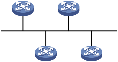
· Broadcast—If the link layer protocol is Ethernet or FDDI, OSPF considers the network type as broadcast by default. On a broadcast network, hello, LSU, and LSAck packets are multicast to 224.0.0.5 that identifies all OSPF routers or to 224.0.0.6 that identifies the DR and BDR. DD packets and LSR packets are unicast.
Figure 16 Broadcast network
 '
'
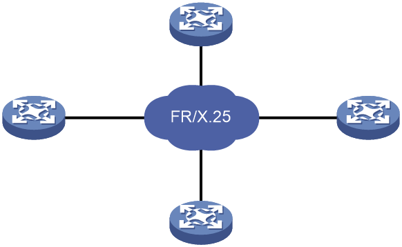
· NBMA—If the link layer protocol is ATM, or X.25, OSPF considers the network type as NBMA by default. OSPF packets are unicast on an NBMA network.
Figure 17 NBMA network.
· P2MP—No link is P2MP type by default. P2MP must be a conversion from other network types such as NBMA. On a P2MP network, OSPF packets are multicast to 224.0.0.5.
Figure 18 P2MP network
· P2P—If the link layer protocol is PPP or HDLC, OSPF considers the network type as P2P. On a P2P network, DD packets are unicast and other OSPF packets are multicast to 224.0.0.5 by default.
Figure 19 P2P network
![]()
The following are the differences between NBMA and P2MP networks:
· NBMA networks are fully meshed. P2MP networks are not required to be fully meshed.
· NBMA networks require DR and BDR election. P2MP networks do not have DR or BDR.
· On an NBMA network, OSPF packets are unicast, and neighbors are manually configured. On a P2MP network, OSPF packets are multicast by default, and you can configure OSPF to unicast protocol packets.
DR and BDR
DR and BDR mechanism
On a broadcast or NBMA network, any two routers must establish an adjacency to exchange routing information with each other. If n routers are present on the network, n(n-1)/2 adjacencies are established. Any topology change on the network results in an increase in traffic for route synchronization, which consumes a large amount of system and bandwidth resources.
Using the DR and BDR mechanisms can solve this problem.
· DR—Elected to advertise routing information among other routers. If the DR fails, routers on the network must elect another DR and synchronize information with the new DR. Using this mechanism without BDR is time-consuming and is prone to route calculation errors.
· BDR—Elected along with the DR to establish adjacencies with all other routers. If the DR fails, the BDR immediately becomes the new DR, and other routers elect a new BDR.
Routers other than the DR and BDR are called DR Others. They do not establish adjacencies with one another, so the number of adjacencies is reduced.
The role of a router is subnet (or interface) specific. It might be a DR on one interface and a BDR or DR Other on another interface.
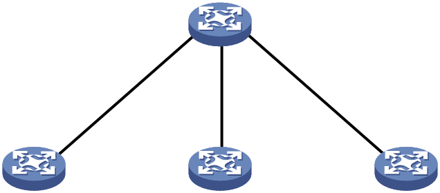
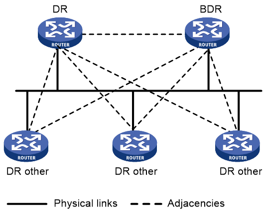
As shown in Figure 20, solid lines are Ethernet physical links, and dashed lines represent OSPF adjacencies. With the DR and BDR, only seven adjacencies are established.
Figure 20 DR and BDR in a network
|
|
NOTE: In OSPF, neighbor and adjacency are different concepts. After startup, OSPF sends a hello packet on each OSPF interface. A receiving router checks parameters in the packet. If the parameters match its own, the receiving router considers the sending router an OSPF neighbor. Two OSPF neighbors establish an adjacency relationship after they synchronize their LSDBs through exchange of DD packets and LSAs. |
DR and BDR election
DR election is performed on broadcast or NBMA networks but not on P2P and P2MP networks.
Routers on a broadcast or NBMA network elect the DR and BDR by router priority and ID. Routers with a router priority value higher than 0 are candidates for DR and BDR election.
The election votes are hello packets. Each router sends the DR elected by itself in a hello packet to all the other routers. If two routers on the network declare themselves as the DR, the router with the higher router priority wins. If router priorities are the same, the router with the higher router ID wins.
If a router with a higher router priority becomes active after DR and BDR election, the router cannot replace the DR or BDR until a new election is performed. Therefore, the DR of a network might not be the router with the highest priority, and the BDR might not be the router with the second highest priority.
OSPF state machines
Interface state machine
On receipt of link state information, OSPF establishes adjacency relationships with neighboring devices, and then exchanges LSAs with them. The state of an OSPF interface indicates the role of the device in an OSPF link. Two neighboring devices can correctly form an adjacency relationship by checking each other's interface state.
The interface state machine involves the following interface states:
· Down—Initial interface state.
An OSPF interface in this state cannot be used for traffic sending or receiving.
· Loopback—The network-attached interface is looped back on the device.
A loopback interface is not available for regular data transmission. However, to obtain link quality information on the interface, you might either send ICMP ping packets to the loopback interface or have a bit error test. To meet this potential requirement, each OSPF device advertises loopback interface information in Router LSAs.
· Waiting—The device is determining the DR and BDR for the network.
When the device does not run for the DR or BDR, the interface starts a wait timer. The hello packets sent by the device does not contain any DR or BDR information unless the wait timer expires. The device cannot be elected as the DR or BDR on the network until it exits from Waiting state. The wait timer mechanism prevents unnecessary DR and BDR changes.
This interface state is supported only on NBMA networks and broadcast networks.
· Point-to-point—The interface is connected to a physical P2P network or to a virtual link.
If an interface enters this state, it attempts to establish an adjacency relationship with the neighboring device.
This interface state is supported only on P2P networks and P2MP networks.
· DR Other—The interface is connected to a broadcast or NBMA network on which another device has been elected as the DR.
A device in DR Other state is neither elected as the DR nor the BDR. When DR and BDR election is complete on the network, each DR Other device establishes adjacencies with both the DR and the BDR.
· BDR—The device is the BDR on the attached network.
As the BDR, the device establishes adjacencies with all other devices on the attached network. It will immediately become the new DR if the existing DR fails.
· DR—The device is the DR on the attached network.
As the DR, the device establishes adjacencies with all other devices on the attached network.
A number of input events (IE) can cause OSPF interface state changes. As shown in Figure 21, the relationships between IEs and state changes form the OSPF interface state machine.
Figure 21 OSPF interface state machine
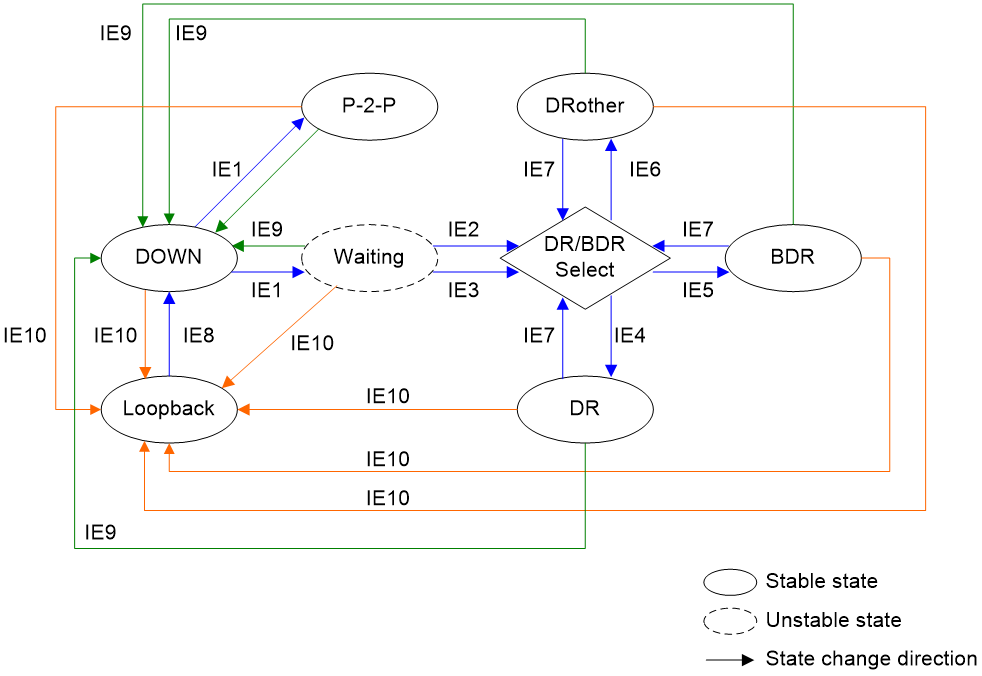
Table 15 shows the IEs that can cause interface state changes.
|
Input event |
Description |
|
IE1 |
InterfaceUp event: Lower-level protocols have indicated that the interface is operational. |
|
IE2 |
WaitTimer event: The wait timer has expired and the device can run for the DR or the BDR. |
|
IE3 |
BackupSeen event: The device has detected the existence or non-existence of a BDR on the attached network through one of the following methods: · The interface receives a hello packet from a neighbor that claims itself to be the BDR. · The interface receives a hello packet from a neighbor that claims itself to be the DR. The hello packet also indicates that there is no BDR. This event marks an end to Waiting state and indicates that the device and the neighbor can have bidirectional communication. |
|
IE4 |
The interface is elected as the DR. |
|
IE5 |
The interface is elected as the BDR. |
|
IE6 |
The interface is neither elected as the DR nor the BDR. |
|
IE7 |
NeighborChange event: A neighbor associated with the interface has a change. The DR and BDR need to be re-elected. The following neighbor changes might lead to the re-election of DR and BDR: · The device can have bidirectional communication with a neighbor. · The device no longer has bidirectional communication with a neighbor. · A neighbor claims itself as DR or BDR. The device detects this event again by examining the hello packets from the neighbor. · A neighbor no longer claims itself as DR or BDR. The device detects this event again by examining the hello packets from the neighbor. · The DR priority for a neighbor has changed. The device detects this event again by examining the hello packets from the neighbor. |
|
IE8 |
UnloopInd event: Network management or lower-level protocols has indicated that the interface is no longer looped back. |
|
IE9 |
InterfaceDown event: Lower-level protocols has indicated that the interface is not operational. If this event occurs, the interface state might change to Down. |
|
IE10 |
LoopInd event: Network management or lower-level protocols has indicated that the interface is looped back. If this event occurs, the interface state might change to Loopback. |
Neighbor state machine
On an OSPF network,
The process of OSPF adjacency establishment involves a series of neighbor state changes that transition from Down state to Full state.
The neighbor state machine involves the following neighbor states:
· Down—Initial state of a neighbor conversation.
This state indicates that the local device does not receive any hello packets from the neighbor within the neighbor dead interval. An OSPF device sends hello packets at intervals of PollInterval.
Whether an OSPF device sends hello packets to neighbors in Down state depends on its network type. The device sends hello packets to neighbors in Down state only when its network type is NBMA.
· Attempt—In this state, the local device attempts to establish neighbor relationships with the manually specified neighbors by sending hello packets at intervals of HelloInterval.
This state is valid only for the neighbors on NBMA networks.
· Init—This state indicates that the local device has received a hello packet from a neighbor before the neighbor dead interval elapses. However, the local device has not established bidirectional communication with the neighbor, because the received hello packet does not contain the local device's router ID.
· 2-Way—This state indicates that the local device has established a neighbor relationship with a neighboring device. Each of the two devices has received a hello packet from another and has seen its own router ID in the received hello packet.
If the neighbor relationship between two devices does not prompt to an adjacency, the neighbor state will remain 2-Way.
DR and BDR election starts only when the neighbor state is 2-Way or greater.
· ExStart—This state indicates that the local device and the neighbor is deciding which is the master. This step is to determine the sequence number for initial DD packets. The devices can then exchange DD packets in order.
· Exchange—This state indicates that the local device is exchanging DD packets with the neighbor. The local device describes its LSDB information in DD packets and sends them to the neighbor.
· Loading—This state indicates that the local device and the neighbor are having bidirectional LSDB synchronization. They send LSRs to each other to request the most recent LSAs, and then synchronize their LSDBs through exchanges of LSUs and LSAcks.
· Full—This state indicates that the local device and the neighbor has completed bidirectional LSDB synchronization and they are fully adjacent.
As shown in Figure 22, the relationships between IEs and state changes form the OSPF neighbor state machine.
Figure 22 OSPF neighbor state machine
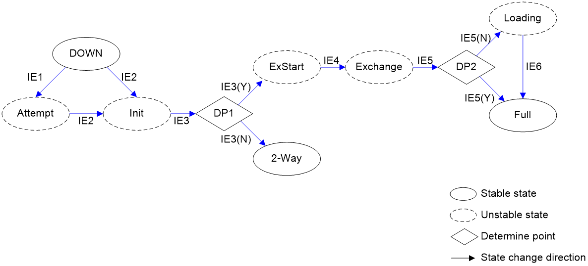
Table 16 shows the IEs that can cause neighbor state changes.
|
Input event |
Description |
|
IE1 |
Start event: The OSPF device attempts to establish a neighbor relationship with the neighbor by sending hello packets at intervals of HelloInterval. This event is supported only on NBMA networks. |
|
IE2 |
HelloReceived event: The OSPF device has received a hello packet from the neighbor. |
|
IE3 |
2-WayReceived event: The OSPF device has received a hello packet from the neighbor and has seen its router ID in the received hello packet. The two neighboring devices have established bidirectional communication. The OSPF device then performs the following task: · If the OSPF device needs to form an adjacency with the neighbor, it changes the neighbor state to ExStart. · If the OSPF device should not form an adjacency with the neighbor, it changes the neighbor state to 2-Way. |
|
IE4 |
NegotiationDone event: The OSPF device and the neighbor have completed master/secondary relationship negotiation and have determined the sequence number for initial DD packets. |
|
IE5 |
ExchangeDone event: The OSPF device have exchanged DD packets with the neighbor. The OSPF device then performs the following task: · If the LSR list is empty, the device changes the neighbor state to Full. This neighbor state indicates that bidirectional LSDB synchronization is complete and the device has established an adjacency with the neighbor. · If the LSR list is not empty, the device changes the neighbor state to Loading, and then sends LSRs to the neighbor to request missing link state information. |
|
IE6 |
LoadingDone event: The LSR list is already empty. |
OSPF route calculation
The route calculation process of the OSPF protocol is as follows:
1. Establish adjacency.
a. The local device transmits hello packets to establish a neighborhood with the remote device.
b. Two devices negotiate master-slave relationships and switch DD packets.
c. Both devices synchronize the LSDB by updating the LSA.
2. OSPF uses the SPF algorithm to calculate routes.
Adjacency establishment
OSPF establishes adjacency relationships differently across various network types.
Establish OSPF adjacency in a broadcast network
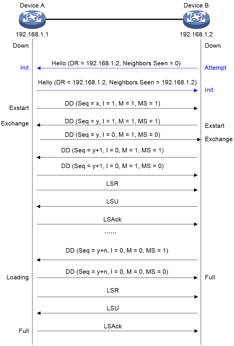
Figure 23 shows the process of establishing OSPF adjacency between devices in a broadcast network.
Figure 23 Establishing OSPF adjacency in a broadcast network

The process for establishing OSPF adjacency between devices in a broadcast network is:
2. Establish a neighbor relationship.
a. Device A enabled OSPF on a broadcast-type network interface and then transmitted a hello packet with the multicast address 224.0.0.5 as the destination IP address. At this point, Device A does not know which device is the Designated Router (DR=0.0.0.0) and is also uncertain about the identity of its neighbors (Neighbors seen=0).
b. After Device B receives the hello packet from Device A, it responds by transmitting a hello packet back to Device A. Device B includes Device A's Router ID (Neighbors seen=192.168.1.1) in the "Neighbors seen" field of the packet, indicating receipt of Device A's hello packet and declaring itself as the Designated Router (DR=192.168.1.2). Then, Device B changes the neighbor state of Device A to Init.
c. After Device A receives the hello packet response from Device B, it changes the state of Device B to 2-way. Next, both devices start transmitting their own link state databases.
|
|
NOTE: In a broadcast network, devices with OSPF interface state set to DR Other do not perform the following steps. |
3. Negotiate master-slave relationships and switch DD packets.
a. Device A first transmits a DD packet, declaring itself as the Master (MS=1), with a sequence number Seq=x. The I=1 indicates this is the first DD packet, which does not include LSA digest information and is only for negotiating the master-slave relationship. M=1 signifies that this is not the final DD packet.
To increase the efficiency of transmission, Device A and Device B first determine which LSAs they need to update. If an LSA already exists in the LSDB, there's no need to request an update. To achieve this, they transmit DD packets containing digest information for each LSA in the LSDB. Both devices can then decide whether an LSA already exists in their LSDB based on the DD packets received from the other device.
To ensure reliable transmission, establish the master-slave relationship before exchanging DD packets. The master sets a sequence number (Seq) and increments it by 1 with each new DD packet sent. The slave uses the Seq from the last DD packet received from the master as the Seq in its own DD packets.
b. After receiving the DD packet transmitted by Device A, Device B transitions the neighbor state of Device A to Exstart and responds with a DD packet that also does not contain LSA digest information. Since Device B has a larger Router ID, it considers itself the Master and resets the sequence number to Seq=y.
c. After Device A receives the DD packet transmitted by Device B, it changes Device B's neighbor state to Exchange. Device A then transmits a DD packet with an LSA digest using sequence number Seq=y. In the packet, Device A sets the MS bit to 0, indicating it is the Slave.
d. After receiving the packet, Device B changes the neighbor state of Device A to Exchange and transmits a DD packet containing the LSA digest with a sequence number Seq=y+1.
Device A and Device B continuously engage in the process described above. During this process, Device A validates receipt of Device B's packets by repeating Device B's sequence number. Device B validates receipt of Device A's packets by incrementing the sequence number, Seq, by 1. When Device B transmits the final DD packet, it sets the M bit to 0.
4. Synchronize the LSDB.
a. After receiving the final Database Description (DD) packet, Device A notices it is missing several Link State Advertisements (LSAs) from Device B's database, and transitions its neighbor state to Loading. At the same time, Device B receives the final DD packet transmitted by Device A. Since Device B already has all LSAs from Device A's Link State Database (LSDB), it transitions the neighbor state of Device A to Full.
b. Device A transmits an LSR packet to request LSA updates from itself. Device B responds to Device A's request by transmitting an LSU packet. Upon receiving the LSU packet, Device A sends an LSAck back to Device B for validation.
The process continues until Device A completes the synchronization of LSAs in Device B's LSDB. At that point, Device A transitions the neighbor state of Device B to Full, and both devices establish their adjacency relationship.
Establish OSPF adjacency in an NBMA network
The process of establishing OSPF adjacency between devices in an NBMA network is as shown. The only difference from establishing adjacency in a broadcast network is the step before switching DD packets.
Figure 24 Establishing OSPF adjacency in an NBMA network
In a broadcast network, the process for establishing OSPF adjacency between devices is as follows:
5. Establish a neighbor relationship
a. After Device B transmits a hello packet to an OSPF protocol interface on Device A with a status of Down, Device B changes the neighbor state to Attempt. At this point, Device B considers itself the DR (DR=192.68.1.2) but is unsure which device is the neighbor (Neighbors=0).
b. After receiving a hello packet, Device A changes the neighbor state of Device B to Init. Then, Device A replies with a hello packet. At this point, Device A accepts Device B as the Designated Router (DR=192.68.1.2) and enters its Router ID (Neighbors Seen=192.68.1.2) in the "Neighbors Seen" field.
|
|
NOTE: In an NBMA network, devices with OSPF interface state set to DR Other do not perform the following steps. |
6. The process of negotiating master/slave relationships and switching DD packets is the same as the process of establishing adjacency relationships in a broadcast network.
7. The process of synchronizing the LSDB is the same as establishing adjacency relationships in a broadcast network.
Route calculation
OSPF uses the Shortest Path First (SPF) algorithm to calculate routes for fast convergence.
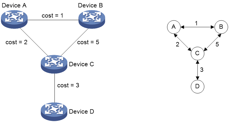
OSPF announces Link State Advertisements (LSAs) to describe network topology information. Each device maintains the topology of the entire autonomous system (AS) through the Link State Database (LSDB) and converts the LSDB into a weighted directed graph. As shown in Figure 25, when the network topology is stable, the weighted directed graphs derived from the LSDB by all devices are identical.
Figure 25 The device generates a weighted directed graph based on the LSDB
As shown in Figure 26, each device calculates its own shortest path tree (SPT) based on a weighted directed graph using the SPF algorithm and builds the routing table accordingly.
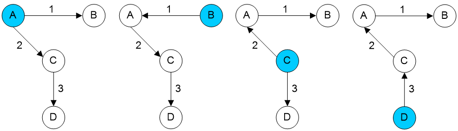
The specific process for route calculation is as follows:
2. Calculate intra-area routes.
Devices calculate the shortest path to other devices within the zone by running the SPF algorithm, which uses the link state information described in Router LSA and Network LSA. If multiple equal cost paths exist, the SPF algorithm reserves all of them in the LSDB.
3. Calculate inter-area routes.
Devices calculate routes to areas outside the zone by running the SPF algorithm, based on link state information described in the Network Summary LSA.
|
|
NOTE: When calculating routes outside its area, an ABR only requires the Network Summary LSA from the backbone area. RFC 1583 compatibility mode and non-compatibility mode affect routing rules. To prevent routing loops, it is best practice for routers within the same routing domain to have a uniform configuration of the same selection rules. |
4. Calculate routes outside the autonomous system.
Devices calculate the shortest path to external autonomous system destinations by running the SPF algorithm based on the link state information described in AS External LSAs.
OSPF multi-process
OSPF supports multi-process. A router can run multiple OSPF processes independently. The routing exchanges between different OSPF processes are performed in the same way as routing exchanges between different routing protocols. A router interface can only run one OSPF process.
A typical application of OSPF multi-process is running OSPF on the PE and CE in a VPN scenario and on the VPN backbone network. On the PE, these two OSPF processes do not interfere with each other.
OSPF default routes
A default route is a route where both the destination address and mask are 0, used when a device does not find an exact match in the routing table entries.
OSPF default routes are typically used in two scenarios:
· The area border router (ABR) releases a default route using Network Summary LSA (Type-3) to direct devices within the area on how to forward packets between areas.
· The autonomous system boundary router (ASBR) releases a default route using either AS External LSA (Type-5) or NSSA External LSA (Type-7) to direct devices within the autonomous system to forward packets to external systems.
The default route released through a Network Summary LSA (Type-3) has a higher privilege level than the default routes released by AS External LSA (Type-5) or NSSA External LSA (Type-7).
The principles for OSPF to release a default route are as follows:
· An OSPF device can only release a default route LSA when it has an external exit.
· If an OSPF device has already released a default route LSA, it will no longer learn default routes of the same type from other devices. That is, during route calculation, default route LSAs released by other devices are not considered, even if they exist in the LSDB.
· If the released external default route depends on other routes, the dependent route must not be one within the same OSPF routing domain, meaning it's not learned by this OSPF process. This is because the purpose of an external default route is to direct packet forwarding outside the domain, while the next hops of routes within the OSPF routing domain all point inward, unable to guide packets outward.
· When a device releases a default route, it checks for neighbors in the FULL state in the backbone area. The device releases the default route only if there are FULL state neighbors in the backbone area. This is because without FULL state neighbors, the backbone area lacks forwarding capability, making the release of a default route meaningless.
Table 17 shows the principles for advertising the default routes in different types of areas.
Table 17 Principles for advertising the default routes in different types of areas
|
Area type |
Principle for advertising a default route |
|
Standard area and backbone area |
Under the default conditions, OSPF devices within a standard OSPF area do not generate a default route, even if one exists on the device. When an ASBR device has a default route generated by other protocols, it must announce this default route throughout the entire OSPF routing domain. To accomplish this, configure the 'default-route-advertise' command on the ASBR device. Once configured, the device will release the default route via Type-5 LSA. A default route is released via Type-5 LSA on an ASBR device only if there is an existing default route generated by another protocol. |
|
Stub area |
Stub areas do not allow the propagation of external routes (Type-5 LSA) from outside the autonomous system within the area. Devices within a Stub area must learn routes external to the autonomous system (AS) through the Area Border Router (ABR). This is achieved by the ABR automatically announcing a default route to the entire Stub area using Type-3 Link State Advertisements (LSAs). Consequently, devices in the Stub area can reach outside the autonomous system (AS) via the ABR. |
|
Totally stub area |
A Totally Stub area does not permit the propagation of external routes from outside the autonomous system (Type-5 LSA) within the area, nor does it allow inter-area routing other than the announce of a default route (Type-3 LSA) to propagate within the area. Devices within a Totally Stub area must learn external routes and routes from other areas via the ABR. To implement this, configure the area as a Totally Stub area, and the ABR will automatically announce a default route to the entire Totally Stub area using Type-3 LSA. This enables devices within the Totally Stub area to reach other areas and the external autonomous system through the ABR. |
|
NSSA area |
Not-so-stubby areas (NSSA) allow devices to introduce external routes without permitting the propagation of external routes (Type-5 LSA) from other areas within the area. If a neighbor in the backbone area is in FULL state and an interface is Up, the ABR will automatically announce a default route to the entire NSSA via Type-7 LSA. Consequently, devices can reach other areas through the ABR. After configuring the command nssa default-route-advertise on the ASBR device, it will announce the default route to the entire NSSA area using Type-7 LSA. Consequently, devices within the NSSA area can generate external routes with the ASBR as the next hop. An ABR will not translate a Type-7 LSA default route into a Type-5 LSA default route and flood it throughout the entire OSPF area. |
|
Totally NSSA area |
A Totally not-so-stubby area (NSSA) neither allows the propagation of external routes (Type-5 LSA) within the area nor permits inter-area routing, except for the announce of the default route (Type-3 LSA). Devices within a Totally NSSA area must learn routes to other areas via the ABR. This is achieved by configuring the area as a Totally NSSA, after which the ABR automatically propagates the default route throughout the Totally NSSA area using Type-3 LSA and Type-7 LSA. Consequently, both external routes from outside the autonomous system and inter-area routing can be propagated within the area through the ABR. |
Virtual links
A virtual link is established between two ABRs through a non-backbone area. It must be configured on both ABRs to take effect. The non-backbone area is called a transit area.
As shown in Figure 27, Area 2 has no direct physical link to the backbone Area 0. You can configure a virtual link between the two ABRs to connect Area 2 to the backbone area.
Figure 27 Virtual link application 1

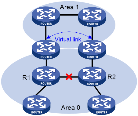
Virtual links can also be used as redundant links. If a physical link failure breaks the internal connectivity of the backbone area, you can configure a virtual link to replace the failed physical link, as shown in Figure 28.
Figure 28 Virtual link application 2
The virtual link between the two ABRs acts as a point-to-point connection. You can configure interface parameters, such as hello interval, on the virtual link as they are configured on a physical interface.
The two ABRs on the virtual link unicast OSPF packets to each other, and the OSPF routers in between convey these OSPF packets as normal IP packets.
OSPF NSSA
Background
A Stub area cannot import external routes, thus reducing the load on devices within the area. However, in scenarios where there's a need to import external routes while avoiding their resource consumption, a Stub area falls short. Therefore, OSPF has defined a new type of area, the not-so-stubby area (NSSA).
Not-so-stubby areas (NSSA) are similar to Stub areas and do not allow Type-5 LSA flooding from other areas into the area. The difference is that NSSA allows the introduction of external routes from outside the autonomous system (AS), which are announced to the area by an ASBR through Type-7 LSA. When Type-7 LSA reaches the ABR of an NSSA, the ABR translates it into Type-5 LSA for propagation to other areas.
N-bit
The Option field in the hello packet transmitted by the device interface includes an N-bit, which describes the device's NSSA capability.
· Setting the N-bit to 1 indicates that the interface transmitting the hello packet is in a not-so-stubby area (NSSA).
· Setting the N-bit to 0 indicates that the interface transmitting the hello packet is not part of a not-so-stubby area (NSSA).
Only devices with the same N-bit can establish OSPF neighbors.
P-bit
The Propagate bit (P-bit) in a Type-7 LSA indicates whether the Area Border Router (ABR) responsible for converting the Type-7 LSA into a Type-5 LSA needs to perform the translation in the not-so-stubby area (NSSA).
Under the default condition, the ABR with the largest Router ID in the not-so-stubby area (NSSA) is responsible for translating Type-7 LSAs into Type-5 LSAs. The ABR only performs this translation when the Type-7 LSA meets the following condition:
· The P-bit is set.
· The Forwarding Address (FA) is not zero. The FA indicates the next-hop address for reaching the route advertised by the Type-7 LSA. OSPF prefers to use the address of a Loopback interface within the area as the FA. If no Loopback interface exists, it selects the address with the smallest logical index from the interfaces that are up within the area.
The default route in the Type-7 LSA generated by ABR does not set the P-bit.
Operating mechanism
As shown in Figure 29, the OSPF AS contains Area 1, Area 2, and Area 0. The other two ASs run RIP. Area 1 is an NSSA area where the ASBR redistributes RIP routes in Type-7 LSAs into Area 1. Upon receiving the Type-7 LSAs, the NSSA ABR translates them to Type-5 LSAs, and advertises the Type-5 LSAs to Area 0.
The ASBR of Area 2 redistributes RIP routes in Type-5 LSAs into the OSPF routing domain. However, Area 1 does not receive Type-5 LSAs because it is an NSSA area.
BFD for OSPF
OSPF periodically sends hello packets to neighbors to detect their states. If OSPF does not receive a hello packet from a neighbor within a specific period, OSPF considers the neighbor unavailable. Such a failure detection mechanism cannot achieve high data reliability, because it takes a long time and causes data loss.
Bidirectional Forwarding Detection (BFD) can quickly detects link faults and informs OSPF, thus enhancing the convergence speed of OSPF when link state changes. The convergence speed comparison of OSPF with and without BFD colleboration is shown in Table 18.
Table 18 Convergence speed with or without BFD for OSPF
|
BFD enabled for OSPF |
Link fault detection mechanism |
Convergence speed |
|
Yes |
The OSPF dead timer expires. |
Seconds |
|
No |
The BFD session state changes to Down. |
Milliseconds |
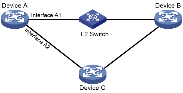
As shown in Figure 30, Device A, Device B, and Device C are OSPF neighbors. When a fault occurs on the link used by Device A and Device B to communicate through the L2 Switch, BFD quickly detects it and announces to OSPF, then performs a switchover to the path through Device C. The specific process is as follows:
2. When the OSPF neighbor state between Device A and Device B changes to Full, OSPF notifies BFD to establish a session.
3. When a link fault occurs on the link for communication between Device A and Device B via an L2 Switch, BFD detects the fault first, sets the session state to Down, and then notifies Device A.
4. After receiving a BFD notification, Device A recalculates the route. The new outgoing interface is Interface A2, which passes through Device C to reach Device B.
Figure 30 OSPF and BFD colleboration
OSPF GTSM
The Generalized TTL Security Mechanism (GTSM) protects the device by comparing the TTL value in the IP header of incoming OSPF packets against a valid TTL range. If the TTL value is within the valid TTL range, the packet is accepted. If not, the packet is discarded.
The valid TTL range is from 255 – the configured hop count + 1 to 255.
When GTSM is configured, the OSPF packets sent by the device have a TTL of 255.
OSPF neighbor flapping suppression
Background
Neighbor state changes will cause neighbor relationship reestablishment, LSDB synchronization, and route calculation. A large number of packets will be exchanged, which affects stability of existing neighbors and operation of OSPF and relevant services. To resolve this issue, enable OSPF neighbor flapping suppression to delay neighbor relationship establishment or traffic forwarding through neighbor links.
Use this feature to avoid frequent flooding and topology changes during neighbor relationship establishment. Before the specified neighbor flapping suppression timer expires, OSPF does not establish neighbor relationships.
Operating mechanism
The OSPF neighbor flapping suppression mechanism is as follows:
· The interface starts a flapping counter to count neighbor flapping events. When the device detects a neighbor flapping event, it increases the flapping counter by 1.
A neighbor flapping event occurs when the time interval between two consecutive neighbor state changes (from Full to another state) is less than the specified detect interval.
· If the time interval between two consecutive neighbor state changes (from Full to another state) is greater than the specified resume interval, the flapping counter is reset.
· If the flapping counter reaches or exceeds the specified threshold, OSPF starts flapping suppression for all neighbors on the interface.
· During the flapping suppression period, if the device detects another neighbor flapping event, it resets the resume interval.
You can enable OSPF neighbor flapping suppression by executing the suppress-flapping hold-down or ospf peer suppress-flapping hold-max-cost command.
· Use the suppress-flapping hold-down command to avoid frequent flooding and topology changes during neighbor relationship establishment. Before the specified neighbor flapping suppression timer expires, OSPF does not establish neighbor relationships.
· Use the ospf peer suppress-flapping hold-max-cost command to set the cost of all neighbor links to the maximum value 65535 within the neighbor flapping suppression period (resume interval).
OSPF neighbor flapping suppression is disabled when one of the following conditions is met:
· The neighbor flapping suppression timer expires.
· The OSPF process is restarted by using the reset ospf process command.
OSPF multi-area adjacency
According to OSPF protocols, intra-area paths have higher priority than inter-area paths. Assume an area contains a high-speed link. Devices in other areas cannot use it for data transmission, because the interface belongs to only one area. To address this issue, you can configure multiple subinterfaces and enable them in different areas. However, this method requires assigning a unique IP address to each subinterface, which increases the total number of routes released by the device.
OSPF multi-area adjacency can enable an OSPF interface into multiple areas, allowing a single path to be shared among multiple areas.
Multi-area adjacency interfaces
You can use the network command or the ospf area command to enable an OSPF interface as the primary interface. Then, use the ospf multi-area command to add more areas to the primary interface. The additional OSPF logical interfaces are multi-area adjacency interfaces.
Multi-area adjacency provides the following features:
· Multi-area adjacency interfaces and the primary interface belong to different OSPF areas.
· The network type for multi-area adjacency interfaces must be P2P, and they run independent OSPF interface state machines and OSPF neighbor state machines.
· Multi-area adjacency interfaces and the primary interface have the same interface type and number, sharing the same packet transmission channel. You can identify whether a packet is sent from a multi-area adjacency interface based on the area ID in the OSPF packet header and the configuration.
Operating mechanism
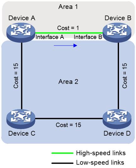
As shown in Figure 31, only the link between Device A and Device B in Area 1 is a high-speed link. Before the OSPF multi-area adjacency feature is enabled, the traffic forwarding path from Device A to Device B in Area 2 is Device A -> Device C -> Device D -> Device B. To use the traffic forwarding path Device A -> Device B, enable the OSPF multi-area adjacency feature.
Figure 31 OSPF multi-area adjacency disabled

As shown in Figure 32, create multi-area adjacency interfaces on primary interfaces Interface A and Interface B on Device A and Device B, respectively. The multi-area adjacency interfaces belong to Area 2. Then, establish neighbor relationship between the multi-area adjacency interfaces on Device A and Device B. When Device A calculates routes to Device B, it finds that the link cost between the multi-area adjacency interfaces in Area 2 is the lowest. Therefore, the traffic forwarding path from Device A to Device B in Area 2 is determined as Device A -> Device B, achieving the goal of sharing a path across multiple areas.
Figure 32 OSPF multi-area adjacency enabled
OSPF FRR
OSPF Fast Reroute (FRR) calculates a backup path based on the LSDB or specifies a backup path by using a routing policy. Then, it saves the backup path information to the FIB. When the primary path fails, the system immediately switches traffic to the backup path to prevent traffic loss and reduce the route convergence time.
OSPF supports Loop Free Alternate (LFA) FRR and remote LFA FRR.
OSPF LFA FRR
A link or router failure on a path can cause packet loss until OSPF completes routing convergence based on the new network topology. FRR enables fast rerouting to minimize the impact of link or node failures.
OSPF remote LFA FRR
In a network topology where OSPF LFA FRR cannot calculate the backup path, configure remote LFA FRR to ensure network reliability.
Remote LFA uses the following concepts:
· P space—Use the source node of the protected link as the root to establish a shortest path tree. All nodes that are reachable from the source node without passing the protected link form the P space. Nodes in the P space are called P nodes.
· Extended P space—Use the source node of the protected link and its neighbors as the roots to establish shortest path trees. All nodes that are reachable from the source node or one of its neighbors without passing the protected link form the extended P space. The P space is a subset of the extended P space.
· Q space—Use the destination node of the protected link as the root to establish a reverse shortest path tree. All nodes that are reachable from the root node without passing the protected link form the Q space. Nodes in the Q space are called Q nodes.
· PQ node—A PQ node refers to a node that resides in both the extended P space and the Q space. Remote LFA uses a PQ node as the destination node of a protected link.
As shown in Figure 33, the traffic forwarding path is PE 1—P 1—P 2—PE 2. To avoid traffic loss caused by link failures between P 1 and P 2, the system establishes an LDP tunnel between P 1 and P 4, which is the PQ node. When the link between P 1 and P 2 fails, P 1 encapsulates IP packets in MPLS packets and sends the MPLS packets to P 4 through the LDP tunnel. After receiving the MPLS packets, P 4 removes the MPLS labels of the packets and then forwards the packets to the next hop based on the IP routing table.
The system determines P 4 as the PQ node as follows:
1. Uses P 1 (source node of the protected link) and its neighbors except P 2 (which passes the protected link) as the roots to establish shortest path trees.
2. Finds out all nodes that are reachable from P 1 or one of its neighbors without passing the protected link, which are PE 1, P 1, P 3, and P 4.
These nodes form the extended P space.
3. Uses P 2 (destination node of the protected link) as the root to establish a reverse shortest path tree.
4. Finds out all nodes that are reachable from P 2 without passing the protected link, which are PE 2 and P 4.
These nodes form the Q space.
5. Finds out all nodes that reside in both the extended P space and the Q space.
Only P 4 resides in both the extended P space and the Q space, so P 4 is the PQ node of the protected link.
Figure 33 Network diagram for OSPF remote LFA FRR

Priority for FRR backup path selection policies
OSPF FRR uses specific policies for backup path calculation. This command defines the priority for the backup path selection policy. The higher the value, the higher the priority of the associated backup path selection policy. Changing the backup path selection policy priority can affect the backup path calculation result for OSPF FRR. The backup paths can provide node protection or link protection for traffic, or provide both node protection and link protection.
OSPF FRR supports the following backup path selection policies that are used to generate different topologies for backup path calculation:
· Node protection—OSPF FRR performs backup path calculation after excluding the primary next hop node.
· Lowest cost—OSPF FRR performs backup path calculation after excluding the direct primary link.
· SRLG disjoint—When one link in the SRLG fails, the other links in the SRLG might also fail. If you use a link in this SRLG as the backup link for the faulty link, protection does not take effect. To avoid this issue, OSPF FRR excludes the local links in the same SRLG as the direct primary link and then performs backup path calculation.
For OSPF FRR, the SRLG disjoint policy depends on the node protection and lowest cost policies.
If multiple backup path selection policies exist in an OSPF process, the policy with the highest priority is used to calculate the backup path. If the policy fails to calculate the backup path, the policy with the highest priority in the remaining policies is used. OSPF performs backup path calculation by using the node protection and lowest cost policies as follows:
· If the node protection policy has higher priority and fails to calculate the backup path, OSPF uses the lowest cost policy to calculate the backup path. If the lowest cost policy still fails to calculate the backup path, reliability cannot be ensured upon primary link failure.
· If the lowest cost policy has higher priority and fails to calculate the backup path, OSPF does not perform further backup path calculation with the node protection policy. Reliability cannot be ensured upon primary link failure.
Table 19 shows the backup path selection mechanism for OSPF FRR based on priorities of backup path selection policies.
Table 19 Backup path selection mechanism for OSPF FRR based on priorities of link selection policies
|
Priorities of link selection policies |
Backup path selection mechanism for OSPF FRR |
|
Node protection > lowest cost > SRLG disjoint |
OSPF FRR performs calculations based on the node protection and lowest cost policies in descending order of priority. OSPF FRR performs a maximum of two calculations. If OSPF FRR calculates a backup path with a link selection policy, it does not perform further calculations. |
|
Node protection > SRLG disjoint > lowest cost |
OSPF FRR performs calculations based on the node protection, node protection + SRLG disjoint, lowest cost + SRLG disjoint, and lowest cost policies in descending order of priority. OSPF FRR performs a maximum of four calculations. If OSPF FRR calculates a backup path with a link selection policy, it does not perform further calculations. |
|
SRLG disjoint > node protection > lowest cost |
OSPF FRR performs calculations based on the node protection + SRLG disjoint, lowest cost + SRLG disjoint, node protection, and lowest cost policies in descending order of priority. OSPF FRR performs a maximum of four calculations. If OSPF FRR calculates a backup path with a link selection policy, it does not perform further calculations. |
|
Lowest cost > node protection > SRLG disjoint |
OSPF FRR performs calculations based on the lowest cost policy. OSPF FRR performs only one calculation. |
|
Lowest cost > SRLG disjoint > node protection |
OSPF FRR performs calculations based on the lowest cost policy. OSPF FRR performs only one calculation. |
|
SRLG disjoint > lowest cost > node protection |
OSPF FRR performs calculations based on the node protection + SRLG disjoint, lowest cost + SRLG disjoint, and lowest cost policies in descending order of priority. OSPF FRR performs a maximum of three calculations. If OSPF FRR calculates a backup path with a link selection policy, it does not perform further calculations. |
In a multi-active and multi-backup scenario, multiple load balancing paths exist between the source node and the destination node. You can enable OSPF FRR to calculate a backup path separately for each load balancing path. By default, OSPF FRR preferentially selects the path with the lowest cost as the backup path when it uses the node protection or lowest cost policy for backup path calculation. OSPF FRR does not identify whether the selected backup path is a load balancing path, except in the following situations:
· OSPF FRR uses the node protection policy to calculate backup paths. Only if the non-ECMP policy takes precedence over the node protection policy, OSPF FRR prefers non-load-balancing paths during backup path selection. If no non-load-balancing path exists, OSPF FRR selects a load balancing path as the backup path. If the lowest cost policy fails to calculate the backup path, OSPF FRR uses the lowest cost policy for further calculation.
· OSPF FRR uses the lowest cost policy to calculate backup paths. Only if the non-ECMP policy takes precedence over the lowest cost policy, OSPF FRR prefers non-load-balancing paths during backup path selection. If no non-load-balancing path exists, OSPF FRR selects a load balancing path as the backup path. If the lowest cost policy fails to calculate the backup path, OSPF FRR does not use the node protection policy to calculate backup paths.
OSPF FRR uses different backup path selection policies to select the backup path as follows:
· Node protection policy.
As shown in Figure 34, Device A uses the node protection policy and selects path Device A->Device B->Device D as the backup path.
Figure 34 Node protection backup path selection

· Lowest cost policy.
As shown in Figure 35, Device A uses the lowest cost policy and selects path Device A->Device E->Device D as the backup path.
Figure 35 Lowest cost backup path selection
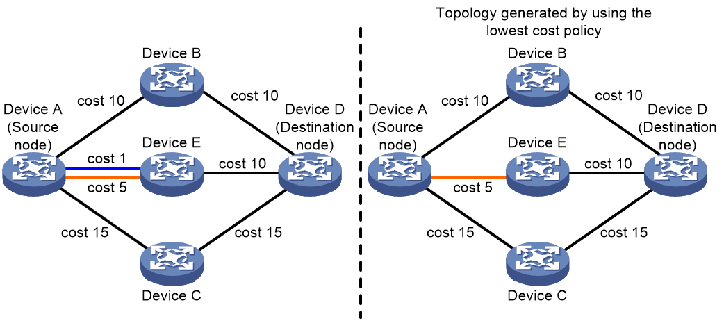
· Node protection and SRLG disjoint policies.
As shown in Figure 36, Device A uses the node protection and SRLG disjoint policies and selects path Device A->Device B->Device D as the backup path.
Figure 36 SRLG disjoint backup path selection

OSPF authentication
OSPF supports packet authentication to prevent routing information leakage and protect OSPF routers from malicious attacks.
OSPF adds the configured key into sent packets, and uses the key to authenticate received packets. Only packets that pass the authentication can be received. If a packet fails the authentication, the OSPF neighbor relationship cannot be established.
OSPF provides the following authentication features:
· Area authentication—Authenticate OSPF packets on all OSPF interfaces in an area. All devices in the same area must have the same authentication settings.
· Interface authentication—Authenticate OSPF packets on an OSPF interfaces. Interfaces attached to the same network segment must have the same authentication settings.
Protocols and standards
· RFC 1245, OSPF protocol analysis
· RFC 1246, Experience with the OSPF protocol
· RFC 1370, Applicability Statement for OSPF
· RFC 1403, BGP OSPF Interaction
· RFC 1745, BGP4/IDRP for IP---OSPF Interaction
· RFC 1765, OSPF Database Overflow
· RFC 1793, Extending OSPF to Support Demand Circuits
· RFC 2154, OSPF with Digital Signatures
· RFC 2328, OSPF Version 2
· RFC 3101, OSPF Not-So-Stubby Area (NSSA) Option
· RFC 3166, Request to Move RFC 1403 to Historic Status
· RFC 3509, Alternative Implementations of OSPF Area Border Routers
· RFC 4167, Graceful OSPF Restart Implementation Report
· RFC 4577, OSPF as the Provider/Customer Edge Protocol for BGP/MPLS IP Virtual Private Networks (VPNs)
· RFC 4750, OSPF Version 2 Management Information Base
· RFC 4811, OSPF Out-of-Band LSDB Resynchronization
· RFC 4812, OSPF Restart Signaling
· RFC 5088, OSPF Protocol Extensions for Path Computation Element (PCE) Discovery
· RFC 5250, The OSPF Opaque LSA Option
· RFC 5613, OSPF Link-Local Signaling
· RFC 5642, Dynamic Hostname Exchange Mechanism for OSPF
· RFC 5709, OSPFv2 HMAC-SHA Cryptographic Authentication
· RFC 5786, Advertising a Router's Local Addresses in OSPF Traffic Engineering (TE) Extensions
· RFC 6571, Loop-Free Alternate (LFA) Applicability in Service Provider (SP) Networks
· RFC 6860, Hiding Transit-Only Networks in OSPF
· RFC 6987, OSPF Stub Router Advertisement
Restrictions and guidelines: OSPF configuration
Before you configure OSPF, make a proper configuration plan to avoid incorrect settings that can result in route blocking and routing loops.
OSPF tasks at a glance
To configure OSPF, perform the following tasks:
1. Configuring basic OSPF functions
2. (Optional.) Configuring OSPF areas
3. (Optional.) Configuring OSPF network types
¡ Configuring the broadcast network type for an interface
¡ Configuring the NBMA network type for an interface
¡ Configuring the P2MP network type for an interface
¡ Configuring the P2P network type for an interface
4. (Optional.) Configuring OSPF route control
¡ Configuring OSPF inter-area route summarization
¡ Configuring redistributed route summarization
¡ Configuring received OSPF route filtering
¡ Configuring Type-3 LSA filtering
¡ Setting an OSPF cost for an interface
¡ Enabling OSPF to advertise the maximum link cost to neighbors
¡ Setting the maximum number of ECMP routes
¡ Configuring discard routes for summary networks
¡ Redistributing routes from another routing protocol
¡ Adjusting the route tagging mechanism to prevent routing loops
¡ Redistributing a default route
¡ Advertising OSPF link state information to BGP
¡ Configuring OSPF to advertise network performance parameters
5. (Optional.) Setting OSPF timers
¡ Configuring OSPF packet timers
¡ Setting LSA transmission delay
¡ Setting SPF calculation interval
¡ Setting the LSA reception interval
¡ Setting the LSA update interval
¡ Setting OSPF exit overflow interval
6. (Optional.) Configuring OSPF packet parameters
¡ Disabling interfaces from receiving and sending OSPF packets
¡ Adding the interface MTU into DD packets
¡ Setting the DSCP value for outgoing OSPF packets
¡ Setting the maximum length of OSPF packets that can be sent by an interface
¡ Enabling OSPF to limit the LSU packet transmission rate
7. (Optional.) Controlling LSA generation, advertisement, and reception
¡ Setting the maximum number of external LSAs in LSDB
¡ Filtering outbound LSAs on an interface
¡ Filtering LSAs for the specified neighbor
¡ Configuring update suppression
8. (Optional.) Accelerating OSPF convergence speed
¡ Configuring prefix suppression
¡ Configuring prefix prioritization
9. (Optional.) Configuring advanced OSPF features
¡ Enabling compatibility with RFC 1583
¡ Configuring OSPF dynamic host name mappings
¡ Configuring OSPF neighbor flapping suppression
¡ Configuring the virtual system feature
10. (Optional.) Enhancing OSPF availability
¡ Enabling OSPF to adjust the interface cost according to the link quality
11. (Optional.) Configuring OSPF security features
¡ Configuring OSPF authentication
12. (Optional.) Configuring OSPF multi-area adjacency
13. (Optional.) Configuring OSPF logging and SNMP notifications
¡ Logging neighbor state changes
¡ Configuring the OSPF logging feature
¡ Configuring OSPF network management
¡ Setting the maximum number of OSPF neighbor relationship troubleshooting entries
Configuring basic OSPF functions
Enabling an OSPF process
1. Enter system view.
system-view
2. (Optional.) Configure a global router ID.
router id router-id
By default, no global router ID is configured.
If no global router ID is configured, the highest loopback interface IP address, if any, is used as the router ID. If no loopback interface IP address is available, the highest physical interface IP address is used, regardless of the interface status (up or down).
3. Enter OSPF view.
ospf [ process-id | router-id { auto-select | router-id } | vpn-instance vpn-instance-name ] *
By default, OSPF is disabled.
4. (Optional.) Configure a description for the OSPF process.
description text
By default, no description is configured for the OSPF process.
As a best practice, configure a description for each OSPF process.
Configuring an OSPF area
1. Enter system view.
system-view
2. (Optional.) Configure a global router ID.
router id router-id
By default, no global router ID is configured.
3. Enter OSPF view.
ospf [ process-id | router-id { auto-select | router-id } | vpn-instance vpn-instance-name ] *
By default, OSPF is disabled.
4. (Optional.) Configure a description for the OSPF process.
description text
By default, no description is configured for the OSPF process.
As a best practice, configure a description for each OSPF process.
5. Create an OSPF area, and enter OSPF area view.
area area-id
6. (Optional.) Configure a description for the area.
description text
By default, no description is configured for the area.
As a best practice, configure a description for each OSPF area.
This configuration is available only in OSPF area view.
Enabling OSPF
About this task
To enable OSPF on a router, you must perform the following tasks:
1. Create an OSPF process.
2. Create an OSPF area for the process.
3. Specify a network in the area.
The interface attached to the network will run the OSPF process in the area. OSPF advertises the direct route of the interface.
OSPF supports multiple processes. To run multiple OSPF processes, you must specify an ID for each process. The process IDs take effect locally and has no influence on packet exchange between routers. Two routers with different process IDs can exchange packets.
You can configure an OSPF process to run in a VPN instance. An OSPF process with no VPN instance specified runs on the public network. For more information about VPN, see MPLS Configuration Guide.
Restrictions and guidelines for enabling OSPF
When you configure OSPF on an interface, follow these restrictions and guidelines:
· You can enable OSPF on the network where the interface resides or directly enable OSPF on that interface. If you configure both, the latter takes precedence.
· If the specified OSPF process and area do not exist, the operation creates an OSPF process and area for the interface. Disabling an OSPF process on an interface does not delete the OSPF process or the area.
Enabling OSPF on a network
1. Enter system view.
system-view
2. Enter OSPF view.
ospf [ process-id | router-id { auto-select | router-id } | vpn-instance vpn-instance-name ] *
3. Enter OSPF area view.
area area-id
4. Specify a network to enable the interface attached to the network to run the OSPF process in the area.
network ip-address wildcard-mask
By default, no network is specified.
A network can be added to only one area.
This configuration is available only in OSPF area view.
Enabling OSPF on an interface
1. Enter system view.
system-view
2. Enter interface view.
interface interface-type interface-number
3. Enable an OSPF process on the interface.
ospf process-id area area-id [ exclude-subip ]
By default, OSPF is disabled on an interface.
Configuring OSPF areas
About OSPF area configuration
This task allows you to configure an OSPF area as a stub area or NSSA area. It also allows you to create a virtual link if no connectivity can be achieved between a non-backbone area and backbone area, or in the backbone area.
Configuring a stub area
About this task
You can configure a non-backbone area at an AS edge as a stub area. To do so, execute the stub command on all routers attached to the area. The routing table size is reduced because Type-5 LSAs will not be flooded within the stub area. The ABR generates a default route into the stub area so all packets destined outside of the AS are sent through the default route.
To further reduce the routing table size and routing information exchanged in the stub area, configure a totally stub area by using the stub no-summary command on the ABR. AS external routes and inter-area routes will not be distributed into the area. All the packets destined for outside of the AS or area will be sent to the ABR for forwarding.
A stub or totally stub area cannot have an ASBR because external routes cannot be distributed into the area.
Restrictions and guidelines
Do not configure the backbone area as a stub area or totally stub area.
To configure an area as a stub area, execute the stub command on all routers attached to the area.
To configure an area as a totally stub area, execute the stub command on all routers attached to the area, and execute the stub no-summary command on the ABR.
Procedure (OSPF area view)
1. Enter system view.
system-view
2. Enter OSPF view.
ospf [ process-id | router-id { auto-select | router-id } | vpn-instance vpn-instance-name ] *
3. Enter area view.
area area-id
4. Configure the area as a stub area.
stub [ default-route-advertise-always | no-summary ] *
By default, no stub area is configured.
5. (Optional.) Set a cost for the default route advertised to the stub area.
default-cost cost-value
By default, the cost is 1 for the default route advertised to the stub area.
This command takes effect only on the ABR of a stub area or totally stub area.
Configuring an NSSA area
About this task
A stub area cannot import external routes, but an NSSA area can import external routes into the OSPF routing domain while retaining other stub area characteristics.
To configure an area as a totally NSSA area, use the nssa no-summary command. The ABR of the area does not advertise inter-area routes into the area.
Restrictions and guidelines
Do not configure the backbone area as an NSSA area or totally NSSA area.
To configure an NSSA area, configure the nssa command on all the routers attached to the area.
To configure a totally NSSA area, configure the nssa command on all the routers attached to the area and configure the nssa no-summary command on the ABR.
Procedure (OSPF area view)
1. Enter system view.
system-view
2. Enter OSPF view.
ospf [ process-id | router-id { auto-select | router-id } | vpn-instance vpn-instance-name ] *
3. Enter area view.
area area-id
4. Configure the area as an NSSA area.
nssa [ default-route-advertise [ cost cost-value | nssa-only | route-policy route-policy-name | type type ] * | no-import-route | no-summary | suppress-fa | [ [ [ translate-always ] [ translate-ignore-checking-backbone ] ] | translate-never ] | translator-stability-interval value ] *
By default, no area is configured as an NSSA area.
5. (Optional.) Set a cost for the default route advertised to the NSSA area.
default-cost cost-value
By default, the cost is 1 for the default route advertised to the NSSA area.
This command takes effect only on the ABR/ASBR on an NSSA area or totally NSSA area.
Configuring a virtual link
About this task
You can configure a virtual link to maintain connectivity between a non-backbone area and the backbone, or in the backbone itself.
Restrictions and guidelines
A virtual link cannot traverse a stub area, totally stub area, NSSA area, or totally NSSA area.
Procedure
1. Enter system view.
system-view
2. Enter OSPF view.
ospf [ process-id | router-id { auto-select | router-id } | vpn-instance vpn-instance-name ] *
area area-id
4. Configure a virtual link.
vlink-peer router-id [ dead seconds | hello seconds | { { hmac-md5 | hmac-sha-256 | md5 } key-id { cipher | plain } string | keychain keychain-name | simple { cipher | plain } string } | retransmit seconds | trans-delay seconds ] *
Configure this command on both ends of a virtual link. The hello and dead intervals must be identical on both ends of the virtual link.
This command is available only in OSPF area view.
Configuring OSPF network types
Based on the link layer protocol, OSPF classifies networks into different types, including broadcast, NBMA, P2MP, and P2P.
Restrictions and guidelines for configuring OSPF network types
When an NBMA network becomes fully meshed, change the network type to broadcast to avoid manual configuration of neighbors.
If any routers in a broadcast network do not support multicasting, change the network type to NBMA.
An NBMA network must be fully meshed. OSPF requires that an NBMA network be fully meshed. If a network is partially meshed, change the network type to P2MP.
If a router on an NBMA network has only one neighbor, you can change the network type to P2P to save costs.
Two broadcast-, NBMA-, and P2MP-interfaces can establish a neighbor relationship only when they are on the same network segment.
Configuring the broadcast network type for an interface
1. Enter system view.
system-view
2. Enter interface view.
interface interface-type interface-number
3. Configure the OSPF network type for the interface as broadcast.
ospf network-type broadcast
By default, the network type of an interface depends on the link layer protocol.
When the link layer protocol is Ethernet or FDDI, OSPF classifies the network type as broadcast by default.
4. (Optional.) Set a router priority for the interface.
ospf dr-priority priority
The default router priority is 1.
Configuring the NBMA network type for an interface
Restrictions and guidelines
After you configure the network type as NBMA, you must specify neighbors and their router priorities because NBMA interfaces cannot find neighbors by broadcasting hello packets.
Procedure
1. Enter system view.
system-view
2. Enter interface view.
interface interface-type interface-number
3. Configure the OSPF network type for the interface as NBMA.
ospf network-type nbma
By default, the network type of an interface depends on the link layer protocol.
When the link layer protocol is ATM or X.25, OSPF classifies the network type as NBMA by default.
4. (Optional.) Set a router priority for the interface.
ospf dr-priority priority
The default router priority for an interface is 1.
The router priority configured with this command is for DR election.
5. Return to system view.
quit
6. Enter OSPF view.
ospf [ process-id | router-id { auto-select | router-id } | vpn-instance vpn-instance-name ] *
7. Specify an NBMA neighbor.
peer ip-address [ dr-priority priority ]
By default, no neighbor is specified.
The priority configured with this command indicates whether a neighbor has the election right or not. If you configure the router priority for a neighbor as 0, the local router determines the neighbor has no election right. It does not send hello packets to this neighbor. However, if the local router is the DR or BDR, it still sends hello packets to the neighbor for neighbor relationship establishment.
Configuring the P2MP network type for an interface
Restrictions and guidelines
After you configure the OSPF network type for an interface as P2MP unicast, all packets are unicast over the interface. The interface cannot broadcast hello packets to discover neighbors, so you must manually specify the neighbors.
Procedure
1. Enter system view.
system-view
2. Enter interface view.
interface interface-type interface-number
3. Configure the OSPF network type for the interface as P2MP.
ospf network-type p2mp [ unicast ]
By default, the network type of an interface depends on the link layer protocol.
4. Return to system view.
quit
5. Enter OSPF view.
ospf [ process-id | router-id { auto-select | router-id } | vpn-instance vpn-instance-name ] *
6. Specify a P2MP neighbor.
peer ip-address [ cost cost-value ]
By default, no neighbor is specified.
This step is required if the interface network type is P2MP unicast.
Configuring the P2P network type for an interface
1. Enter system view.
system-view
2. Enter interface view.
interface interface-type interface-number
3. Configure the OSPF network type for the interface as P2P.
ospf network-type p2p [ multicast | peer-address-check ] *
By default, the network type of an interface depends on the link layer protocol.
When the link layer protocol is PPP, LAPB, or HDLC, OSPF classifies the network type as P2P by default.
Configuring OSPF route control
This section describes how to control the advertisement and reception of OSPF routing information, as well as route redistribution from other protocols.
Configuring OSPF inter-area route summarization
About this task
OSPF inter-area route summarization reduces the routing information exchanged between areas and the size of routing tables, and improves routing performance.
OSPF inter-area route summarization enables an ABR to summarize contiguous networks into a single network and advertise the network to other areas. For example, three internal networks 19.1.1.0/24, 19.1.2.0/24, and 19.1.3.0/24 are available within an area. You can configure the ABR to summarize the three networks into network 19.1.0.0/16, and advertise the summary network to other areas in a Type-3 LSA. This configuration reduces the scale of LSDBs on routers in other areas and the influence of topology changes.
Procedure
1. Enter system view.
system-view
2. Enter OSPF view.
ospf [ process-id | router-id { auto-select | router-id } | vpn-instance vpn-instance-name ] *
3. Enter OSPF area view.
area area-id
4. Configure ABR route summarization.
abr-summary ip-address { mask-length | mask } [ advertise | not-advertise ] [ cost cost-value ]
By default, route summarization is not configured on an ABR.
Configuring redistributed route summarization
About this task
Perform this task to enable an ASBR to summarize external routes within the specified address range into a single route. The ASBR advertises only Type-5 LSAs to reduce the number of LSAs in the LSDB.
An ASBR can summarize routes in the following LSAs:
· Type-5 LSAs.
· Type-7 LSAs in an NSSA area.
Restrictions and guidelines
If an ASBR (also an ABR) is a translator in an NSSA area, it summarizes routes in Type-5 LSAs translated from Type-7 LSAs. If it is not a translator, it does not summarize routes in in Type-5 LSAs translated from Type-7 LSAs.
Procedure
1. Enter system view.
system-view
2. Enter OSPF view.
ospf [ process-id | router-id { auto-select | router-id } | vpn-instance vpn-instance-name ] *
3. Configure ASBR route summarization.
asbr-summary ip-address { mask-length | mask } [ cost cost-value | not-advertise | nssa-only | tag tag ] *
By default, route summarization is not configured on an ASBR.
Configuring received OSPF route filtering
About this task
Perform this task to filter routes calculated using received LSAs.
The following filtering methods are available:
· Use an ACL or IP prefix list to filter routing information by destination address.
· Use the gateway prefix-list-name option to filter routing information by next hop.
· Use an ACL or IP prefix list to filter routing information by destination address. At the same time use the gateway prefix-list-name option to filter routing information by next hop.
· Use the route-policy route-policy-name option to filter routing information.
Procedure
1. Enter system view.
system-view
2. Enter OSPF view.
ospf [ process-id | router-id { auto-select | router-id } | vpn-instance vpn-instance-name ] *
3. Configure OSPF to filter routes calculated using received LSAs.
filter-policy { ipv4-acl-number [ gateway prefix-list-name ] | gateway prefix-list-name | prefix-list prefix-list-name [ gateway prefix-list-name ] | route-policy route-policy-name } import
By default, OSPF accepts all routes calculated by using received LSAs.
Configuring Type-3 LSA filtering
About this task
Perform this task to filter Type-3 LSAs advertised into the local area or other areas on an ABR.
Procedure
1. Enter system view.
system-view
2. Enter OSPF view.
ospf [ process-id | router-id { auto-select | router-id } | vpn-instance vpn-instance-name ] *
3. Enter OSPF area view.
area area-id
4. Configure Type-3 LSA filtering.
filter { ipv4-acl-number | prefix-list prefix-list-name | route-policy route-policy-name } { export | import }
By default, the ABR does not filter Type-3 LSAs.
Setting an OSPF cost for an interface
About this task
Set an OSPF cost for an interface by using either of the following methods:
· Set the cost value in interface view.
· Set a bandwidth reference value for the interface. OSPF computes the cost with this formula: Interface OSPF cost = Bandwidth reference value (100 Mbps) / Expected interface bandwidth (Mbps). The expected bandwidth of an interface is configured with the bandwidth command (see Interface Command Reference).
¡ If the calculated cost is greater than 65535, the value of 65535 is used. If the calculated cost is less than 1, the value of 1 is used.
¡ If no cost or bandwidth reference value is configured for an interface, OSPF computes the interface cost based on the interface bandwidth and default bandwidth reference value.
Setting an OSPF cost for an interface
1. Enter system view.
system-view
2. Enter interface view.
interface interface-type interface-number
3. Set an OSPF cost for the interface.
ospf cost cost-value
By default, the OSPF cost is calculated according to the interface bandwidth. For a loopback interface, the OSPF cost is 0 by default.
Setting a bandwidth reference value
1. Enter system view.
system-view
2. Enter OSPF view.
ospf [ process-id | router-id { auto-select | router-id } | vpn-instance instance-name ] *
3. Set a bandwidth reference value.
bandwidth-reference value
The default setting is 100 Mbps.
Changing the link cost of a Layer 3 aggregate interface when its bandwidth falls below the threshold
About this task
When a member port of a Layer 3 aggregate interface goes down, the bandwidth of the aggregate interface decreases and services might be interrupted. To resolve this issue, perform this task to change the link cost of a Layer 3 aggregate interface as follows:
· When the bandwidth of the Layer 3 aggregate interface falls below the specified threshold, the aggregate interface uses the specified link cost. Make sure the link cost you specified is larger than the original link cost, so that OSPF can select an optimal path for traffic forwarding.
· When the bandwidth of the Layer 3 aggregate interface is equal to or larger than the bandwidth threshold, the aggregate interface uses the original link cost.
For more information about OSPF link cost, see "Setting an OSPF cost for an interface."
Restrictions and guidelines
This feature applies to only Layer 3 aggregate interfaces and Layer 3 aggregate subinterfaces.
Procedure
1. Enter system view.
system-view
2. Enter interface view.
interface interface-type interface-number
3. Change the link cost of the interface to the specified value when the bandwidth of the interface falls below the specified threshold.
ospf cost-fallback cost-value threshold bandwidth-value [ instance instance-id ]
By default, an aggregate interface uses the original link cost.
Enabling OSPF to advertise the maximum link cost to neighbors
About this task
On an OSPF network, when a link recovers from failures or the state of an interface changes, OSPF will re-establish neighbor relationships and perform route convergence. During the route convergence process, routing loops and traffic loss might occur because the convergence speeds of the nodes are different. To address this issue, enable OSPF to advertise the maximum link cost to neighbors within the specified period of time, so the traffic forwarding path remains unchanged. After the specified period of time, OSPF advertises the original link cost to neighbors and performs optimal route selection again.
Procedure
1. Enter system view.
system-view
2. Enter interface view.
interface interface-type interface-number
3. Enable OSPF to advertise the maximum link cost to neighbors within the specified period of time.
ospf peer hold-max-cost duration time
By default, OSPF advertises the original link cost to neighbors during route convergence.
Setting the maximum number of ECMP routes
About this task
OSPF might find multiple optimal equal-cost routes to the same destination, which can be used to share the traffic load. This task allows you to set the maximum number of ECMP routes for OSPF.
As shown in Figure 37, Device A and Device B run OSPF. There are three equal-cost routes between Device A and Device B. You can use these routes to implement load sharing.
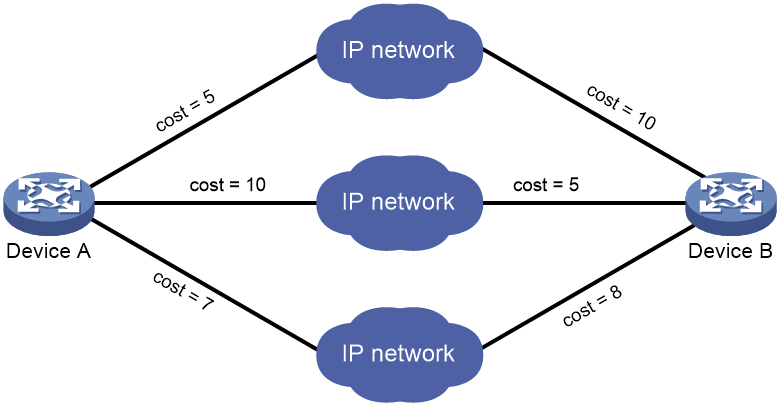
Procedure
1. Enter system view.
system-view
2. Enter OSPF view.
ospf [ process-id | router-id { auto-select | router-id } | vpn-instance vpn-instance-name ] *
3. Set the maximum number of ECMP routes.
maximum load-balancing number
By default, the maximum number of OSPF ECMP routes is 64.
Setting OSPF preference
About this task
A router can run multiple routing protocols, and each protocol is assigned a preference. If multiple routes are available to the same destination, the one with the highest protocol preference is selected as the best route.
Procedure
1. Enter system view.
system-view
2. Enter OSPF view.
ospf [ process-id | router-id { auto-select | router-id } | vpn-instance vpn-instance-name ] *
3. Set a preference for OSPF.
preference [ ase ] { preference | route-policy route-policy-name } *
By default, the preference of OSPF internal routes is 10 and the preference of OSPF external routes is 150.
Configuring discard routes for summary networks
About this task
Perform this task on an ABR or ASBR to specify whether to generate discard routes for summary networks. You can also specify a preference for the discard routes.
Procedure
1. Enter system view.
system-view
2. Enter OSPF view.
ospf [ process-id | router-id { auto-select | router-id } | vpn-instance vpn-instance-name ] *
3. Configure discard routes for summary networks.
discard-route { external { preference | suppression } | internal { preference | suppression } } *
By default, the ABR or ASBR generates discard routes for summary networks and the default preference of discard routes is 255.
Redistributing routes from another routing protocol
About this task
When an OSPF device does not have routes from a non-OSPF routing protocol, it cannot access any devices that run the non-OSPF routing protocol. To resolve this issue, you can configure OSPF to redistribute routes from other protocols, such as IS-IS and BGP. OSPF can then advertise the routes in Type-5 LSAs or Type-7 LSAs.
In addition, you can configure OSPF to filter redistributed routes so that OSPF advertises only permitted routes.
Restrictions and guidelines
Although OSPF is a dynamic routing protocol that provides loop-free intra-area/inter-area routes, this protocol is not good at guarding against the routing loops caused by redistributed external routes. When you configure route redistribution for OSPF, make sure you have understood the potential impact.
OSPF redistributes only active routes. To view route status information, use the display ip routing-table protocol command.
Procedure
1. Enter system view.
system-view
2. Enter OSPF view.
ospf [ process-id | router-id { auto-select | router-id } | vpn-instance vpn-instance-name ] *
3. Configure route redistribution.
import-route bgp [ as-number ] [ allow-ibgp ] [ [ cost cost-value | inherit-cost ] | nssa-only | route-policy route-policy-name | tag tag | type type ] *
import-route { direct | static | unr } [ [ cost cost-value | inherit-cost ] | nssa-only | route-policy route-policy-name | tag tag | type type ] *
import-route eigrp [ eigrp-as | all-as ] [ allow-direct | [ cost cost-value | inherit-cost ] | nssa-only | route-policy route-policy-name | tag tag | type type ] *
import-route { isis | ospf | rip } [ process-id | all-processes ] [ allow-direct | [ cost cost-value | inherit-cost ] | nssa-only | route-policy route-policy-name | tag tag | type type ] *
By default, OSPF does not redistribute routes.
The import-route bgp command redistributes only EBGP routes. The import-route bgp allow-ibgp command redistributes both EBGP and IBGP routes, which might cause routing loops. Therefore, use it with caution.
4. (Optional.) Configure OSPF to filter redistributed routes.
filter-policy { ipv4-acl-number | prefix-list prefix-list-name } export [ bgp | direct | eigrp [ eigrp-as ] | { isis | ospf | rip } [ process-id ] | static | unr ]
By default, OSPF accepts all redistributed routes.
5. Configure the default parameters for redistributed routes (cost, tag, and type).
default { cost cost-value | tag tag | type type } *
By default, the cost is 1, the tag is 1, and the route type is 2.
Adjusting the route tagging mechanism to prevent routing loops
About this task
Perform this task to resolve routing loop issues in the scenario meeting the following conditions:
· The CE is dual-homed (connecting to two PEs) and uses OSPF to exchange private network routes with the PEs.
· One of the two PEs is an H3C device and the other PE is from another vendor.
When a PE redistributes BGP routes into OSPF and advertises them to the CE in a Type 5 or 7 LSA, it adds an external-route tag to the LSA. On receipt of the Type 5 or 7 LSAs advertised by the CE, the other PE compares the external-route tag in the LSA against the local external-route tag. If they are the same, the PE ignores the LSA to avoid routing loops. Since different vendors use different external route tagging mechanisms, the PE might add the LSA into its LSDB and perform route calculation based on the LSA, thus causing loops.
To resolve the issue, perform this task on the H3C device. After you configure this task, OSPF is disabled from inheriting the tag carried by the redistributed route. To ensure consistency with the external route tagging mechanisms of other vendors, OSPF selects a tag for the redistributed route as follows:
1. Tag specified by using the apply tag command in a routing policy.
2. Tag specified by the tag option of the import-route command.
3. Tag specified by the route-tag command.
4. If the BGP AS number is less than or equal to 65535, the first two bytes of the external-route tag value are fixed at 0xD000, and the following two bytes are the local BGP AS number. If the BGP AS number is greater than 65535, the external-route tag value is 0. For example, if the local BGP AS number is 100, the default external-route tag value in decimal notation is 3489661028, which is 0xD0000000 (3489660928 in decimal notation) plus 100.
For more information about the CE dual-homed scenario and route tags, see MPLS L3VPN configuration in MPLS Configuration Guide.
Procedure (OSPF view)
1. Enter system view.
system-view
2. Enter OSPF view.
ospf [ process-id | router-id { auto-select | router-id } | vpn-instance vpn-instance-name ] *
3. Disable OSPF from inheriting the tags of redistributed routes.
import-route no-inherit-tag
By default, OSPF inherits the tags of redistributed routes.
Redistributing a default route
About this task
On a OSPF network, multiple ABRs and ASBRs work together to implement multi-egress redundancy or load balancing. To save routing table capacity, you can configure default routes.
OSPF default routes are mostly used in the following scenarios:
· After receiving a Type-3 LSA that describes a default route from the ABR, the intra-area router can use the route for packet forwarding to another area in the same AS.
· After receiving a Type-5 or Type-7 LSA that describes a default route from the ASBR, the intra-area router can use the route for packet forwarding to another AS.
When a router cannot find a exactly matching route, it can use the default route for packet forwarding. The default route originated from a Type-3 LSA takes precedence over that originated from a Type 5 LSA.
As shown in Table 20, the advertisement method for a redistributed default route varies by its area type.
Table 20 Advertisement of redistributed default routes
|
Area type |
Route redistribution condition |
Advertiser |
LSA type |
LSA flooding scope |
|
Common area |
Use the default-route-advertise command. |
ASBR |
Type-5 LSA |
Common area |
|
Stub area |
Automatic route redistribution. |
ABR |
Type-3 LSA |
Stub area |
|
NSSA area |
Use the nssa [ default-route-advertise ] command. |
ASBR |
Type-7 LSA |
NSSA area |
|
Totally NSSA area |
Automatic route redistribution. |
ABR |
Type-3 LSA |
NSSA area |
The import-route command cannot redistribute a default route from an external routing protocol. To resolve this issue, perform this task on the ASBR to redistribute a default route.
Restrictions and guidelines
After receiving a default route from the ASBR, the device can add the default route to its routing table in one of the following scenarios:
· The device does not have a static route.
· The device has a static route, but the priority value for the default route is higher than that for the static route.
Procedure
1. Enter system view.
system-view
2. Enter OSPF view.
ospf [ process-id | router-id { auto-select | router-id } | vpn-instance vpn-instance-name ] *
3. Redistribute a default route.
default-route-advertise [ [ always | permit-calculate-other ] | cost cost-value | route-policy route-policy-name | type type ] *
default-route-advertise [ summary cost cost-value ]
By default, no default route is redistributed.
This command is applicable only to VPNs. The PE router advertises a default route in a Type-3 LSA to a CE router.
4. Configure the default parameters for redistributed routes (cost, tag, and type).
default { cost cost-value | tag tag | type type } *
By default, the cost is 1, the tag is 1, and the route type is 2.
Advertising a host route
1. Enter system view.
system-view
2. Enter OSPF view.
ospf [ process-id | router-id { auto-select | router-id } | vpn-instance vpn-instance-name ] *
3. Enter area view.
area area-id
4. Advertise a host route.
host-advertise ip-address cost-value
By default, OSPF does not advertise host routes that are not in the area.
Advertising OSPF link state information to BGP
About this task
After the device advertises OSPF link state information to BGP, BGP can advertise the information for intended applications. For more information about BGP LS, see "Configuring BGP."
Procedure
1. Enter system view.
system-view
2. Enter OSPF view.
ospf [ process-id | router-id { auto-select | router-id } | vpn-instance vpn-instance-name ] *
3. Advertise OSPF link state information to BGP.
distribute bgp-ls [ instance-id id ] [ strict-link-checking ]
By default, the device does not advertise OSPF link state information to BGP.
Configuring OSPF to advertise network performance parameters
About OSPF network performance parameters
A controller in a network performance-sensitive scenario uses parameters that can reflect the network performance as route calculation metrics.
Perform this task to enable OSPF to advertise network performance parameters and report the information to the controller through BGP-LS. Then, the controller performs optimal route calculation based on the network performance parameters.
Network performance parameters include the following:
· Delay—Unidirectional link delay performance metrics, including:
¡ Average link delay—Average unidirectional link delay.
¡ Min/Max link delay—Minimum/maximum unidirectional link delay.
¡ Average link delay variation—Average unidirectional link delay variation.
· Bandwidth—Unidirectional link bandwidth performance metrics, including:
¡ Remaining bandwidth—Remaining unidirectional link bandwidth.
¡ Available bandwidth—Available unidirectional link bandwidth.
¡ Utilized bandwidth—Unidirectional link bandwidth usage.
Advertising link delay information
About this task
Perform this task to enable OSPF to advertise link delay information and report the information to the controller through BGP-LS. Then, the controller performs optimal route calculation based on the link delay information.
Perform either of the following tasks to obtain link delay information of an interface:
· Static configuration—Execute the ospf link-delay command to manually configure link delay parameters on the interface.
· Dynamic acquisition—Execute the test-session bind interface command to bind the interface as the out interface of a TWAMP Light test session. Then, TWAMP Light will send the detected link delay information to the interface, and the interface will report the link delay information to OSPF at periodic intervals. For more information about TWAMP Light, see NQA configuration in Network Management and Monitoring Configuration Guide.
In dynamic acquisition mode, an interface reports link delay information to OSPF at rather short intervals, for example, 100 milliseconds. As a result, OSPF needs to frequently process the link delay information and reports the information to the controller through BGP-LS, which consumes a lot of device and network resources. To resolve this issue, you can configure OSPF to suppress advertisement of link delay information.
Link delay advertisement suppression works as follows:
· An interface reports link delay information to OSPF at the specified interval.
· OSPF advertises link delay information through BGP-LS at intervals specified by the timer-value argument. OSPF does not advertise link delay information within the specified interval except for the following conditions:
¡ The variation ratio between two consecutive minimum delays is larger than or equivalent to the suppression threshold for the delay variation ratio.
¡ The absolute value of the difference between two consecutive minimum delays is larger than or equivalent to the suppression threshold for the absolute value of the delay variation.
Restrictions and guidelines
For an interface, static link delay parameters take precedence over the parameters obtained through dynamic acquisition.
As a best practice, set the link delay advertisement suppression interval to be larger than or equivalent to the NQA delay measurement interval.
Configuring link delay parameters
1. Enter system view.
system-view
2. Enter interface view.
interface interface-type interface-number
3. Configure link delay parameters.
ospf link-delay { average average-delay-value | min min-delay-value max max-delay-value | variation variation-value} *
By default, link delay parameters are not configured.
Enabling OSPF to advertise link delay information
1. Enter system view.
system-view
2. Enter OSPF view.
ospf [ process-id | router-id { auto-select | router-id } | vpn-instance vpn-instance-name ] *
3. Enable OSPF to advertise link delay information.
metric-delay advertisement enable
By default, OSPF does not advertise link delay information.
Configuring the suppression settings for OSPF to suppress link delay information advertisement
1. Enter system view.
system-view
2. Enter OSPF view.
ospf [ process-id | router-id { auto-select | router-id } | vpn-instance vpn-instance-name ] *
3. Configure the suppression settings for OSPF to suppress link delay information advertisement.
metric-delay suppression timer timer-value percent-threshold percent-value absolute-threshold absolute-value
By default, the suppression interval is 120 seconds, the suppression threshold for the delay variation ratio is 10%, and the suppression threshold for the absolute value of the delay variation is 1000 microseconds.
If you set an argument to 0, the corresponding suppression mechanism does not take effect.
Advertising link bandwidth information
About this task
Perform this task to enable OSPF to advertise link bandwidth information and report the information to the controller through BGP-LS. Then, the controller performs optimal route calculation based on the link bandwidth information.
By default, an interface reports link bandwidth information to OSPF at short intervals, for example, 100 milliseconds. As a result, OSPF needs to frequently process the link bandwidth information and reports the information to the controller through BGP-LS, which consumes a lot of device and network resources. To resolve this issue, you can configure OSPF to suppress advertisement of link bandwidth information.
Link bandwidth advertisement suppression works as follows:
· An interface reports link bandwidth information to OSPF at the specified interval.
· OSPF advertises link bandwidth information through BGP-LS at intervals specified by the timer-value argument.
Restrictions and guidelines
As a best practice, set the link bandwidth advertisement suppression interval to be larger than or equivalent to the Ethernet interface bandwidth measurement interval.
Enabling OSPF to advertise link bandwidth information
1. Enter system view.
system-view
2. Enter OSPF view.
ospf [ process-id | router-id { auto-select | router-id } | vpn-instance vpn-instance-name ] *
3. Enable OSPF to advertise link bandwidth information.
metric-bandwidth advertisement enable
By default, OSPF does not advertise link bandwidth information.
Setting the suppression interval for OSPFv3 to suppress link bandwidth information advertisement
1. Enter system view.
system-view
2. Enter OSPF view.
ospf [ process-id | router-id { auto-select | router-id } | vpn-instance vpn-instance-name ] *
3. Sett the suppression interval for OSPF to suppress link bandwidth information advertisement.
metric-bandwidth suppression timer time-value
By default, the suppression interval is 120 seconds.
If you set the timer-value argument to 0, OSPF does not suppress advertisement of link bandwidth information.
Setting OSPF timers
About setting OSPF timers
This task allows you to change OSPF packet timers to adjust the convergence speed and network load and tune the delay time for sending LSAs on low-speed links.
Configuring OSPF packet timers
About this task
An OSPF interface includes the following timers:
· Hello timer—Interval for sending hello packets. It must be identical on OSPF neighbors.
· Poll timer—Interval for sending hello packets to a neighbor that is down on the NBMA network.
· Dead timer—Interval within which if the interface does not receive any hello packet from the neighbor, it declares the neighbor is down.
· LSA retransmission timer—Interval within which if the interface does not receive any acknowledgment packets after sending an LSA to the neighbor, it retransmits the LSA.
Restrictions and guidelines
The default value for the hello interval and neighbor dead interval depends on the network type. When the network type for an interface is changed, the default hello interval and neighbor dead interval are restored. Make sure two neighboring interfaces are configured with the same hello interval and neighbor dead interval. Inconsistent settings will affect the OSPF neighbor relationship establishment.
Procedure
1. Enter system view.
system-view
2. Enter interface view.
interface interface-type interface-number
3. Set the hello interval.
ospf timer hello seconds
By default, the hello interval is 10 seconds on P2P and broadcast interfaces and 30 seconds on P2MP and NBMA interfaces.
4. Set the poll interval.
ospf timer poll seconds
The default setting is 120 seconds.
The poll interval is a minimum of four times the hello interval.
5. Set the dead interval.
ospf timer dead seconds
By default, the dead interval is 40 seconds on P2P and broadcast interfaces and 120 seconds on P2MP and NBMA interfaces.
The dead interval must be a minimum of four times the hello interval on an interface.
6. Set the retransmission interval.
ospf timer retransmit interval
The default retransmission interval is 5 seconds.
A retransmission interval setting that is too small can cause unnecessary LSA retransmissions. Typically set a bigger interval than the round-trip time of a packet between two neighbors.
Setting LSA transmission delay
About this task
To avoid LSAs from aging out during transmission, set an LSA retransmission delay especially for low speed links.
Procedure
1. Enter system view.
system-view
2. Enter interface view.
interface interface-type interface-number
3. Set the LSA transmission delay.
ospf trans-delay seconds
The default LSA transmission delay is 1 second.
Setting SPF calculation interval
About this task
LSDB changes result in SPF calculations. When the topology changes frequently, a large amount of network and router resources are occupied by SPF calculation. You can adjust the SPF calculation interval to reduce the impact.
For a stable network, the minimum interval is used. If network changes become frequent, the SPF calculation interval increases by the incremental interval × 2n-2 for each calculation until the maximum interval is reached. The value n is the number of calculation times.
Procedure
1. Enter system view.
system-view
2. Enter OSPF view.
ospf [ process-id | router-id { auto-select | router-id } | vpn-instance vpn-instance-name ] *
3. Set the SPF calculation interval.
spf-schedule-interval { maximum-interval [ minimum-interval [ incremental-interval [ conservative ] ] ] | millisecond interval }
By default, the maximum interval is 5 seconds, the minimum interval is 50 milliseconds, and the incremental interval is 200 milliseconds.
Setting the LSA reception interval
About this task
An LSA is a duplicate of a previous LSA if they have the same LSA type, LS ID, and router ID. OSPF drops any duplicate LSAs within an LSA reception interval.
The default LSA reception interval settings are as follows:
· The reception interval for the first LSA is 500 milliseconds.
· The reception interval for the nth (n ≥ 2) LSA is 500 + (500 x 2n-2) milliseconds, and cannot exceed 1000 milliseconds.
· OSPF drops duplicate LSAs received within an LSA reception interval.
You can use the lsa-arrival-interval command to adjust the LSA reception interval settings, and the configuration functions as follows:
· If the lsa-arrival-interval maximum-interval command is executed:
¡ The values for the minimum-interval and incremental-interval arguments are both 0.
¡ The LSA reception interval is fixed at maximum-interval.
OSPF drops duplicate LSAs received within an LSA reception interval.
· If the lsa-arrival-interval maximum-interval minimum-interval command is executed:
¡ The value for the incremental-interval argument is 0.
¡ The reception interval for the first LSA is minimum-interval.
¡ The reception interval for subsequent LSAs is maximum-interval.
OSPF drops duplicate LSAs received within an LSA reception interval.
· If the lsa-arrival-interval maximum-interval minimum-interval incremental-interval command is executed:
¡ The reception interval for the first LSA is minimum-interval.
¡ The reception interval for the nth (n ≥ 2) LSA is minimum-interval + incremental-interval x 2n-2, and cannot exceed maximum-interval.
OSPF drops duplicate LSAs received within an LSA reception interval.
Restrictions and guidelines
On a stable network that requires fast convergence, you can set the LSA reception interval to 0 for OSPF. In this way, OSPF can learn the changes of the topology or routes immediately.
Procedure
1. Enter system view.
system-view
2. Enter OSPF view.
ospf [ process-id | router-id { auto-select | router-id } | vpn-instance vpn-instance-name ] *
3. Set the LSA reception interval.
lsa-arrival-interval maximum-interval [ minimum-interval [ incremental-interval ] ]
By default, the maximum interval is 1000 milliseconds, the minimum interval is 500 milliseconds, and the incremental interval is 500 milliseconds.
Setting the LSA update interval
About this task
If network changes become frequent, bandwidth resources and router resources might be overconsumed. To avoid this issue, use the lsa-generation-interval command to adjust the LSA update interval settings for OSPF.
The default LSA update interval settings are as follows:
· The update interval for the first LSA is 50 milliseconds.
· The update interval for the nth (n ≥ 2) LSA is 50 + (200 x 2n-2) milliseconds, and cannot exceed 5 seconds.
The lsa-generation-interval command functions as follows:
· If the lsa-generation-interval maximum-interval command is executed:
¡ The values for the minimum-interval and incremental-interval arguments are both 0.
¡ The LSA update interval is fixed at maximum-interval.
· If the lsa-generation-interval maximum-interval minimum-interval command is executed:
¡ The value for the incremental-interval argument is 0.
¡ The update interval for the first LSA is minimum-interval.
¡ The update interval for subsequent LSAs is maximum-interval.
· If the lsa-generation-interval maximum-interval minimum-interval incremental-interval command is executed:
¡ The update interval for the first LSA is minimum-interval.
¡ The update interval for the nth (n ≥ 2) LSA is minimum-interval + incremental-interval x 2n-2, and cannot exceed maximum-interval.
Procedure
1. Enter system view.
system-view
2. Enter OSPF view.
ospf [ process-id | router-id { auto-select | router-id } | vpn-instance vpn-instance-name ] *
3. Set the LSA update interval.
lsa-generation-interval maximum-interval [ minimum-interval [ incremental-interval ] ]
By default, the maximum interval is 5 seconds, the minimum interval is 50 milliseconds, and the incremental interval is 200 milliseconds.
Setting OSPF exit overflow interval
About this task
When the number of LSAs in the LSDB exceeds the upper limit, the LSDB is in an overflow state. In this state, OSPF does not receive any external LSAs and deletes the external LSAs generated by itself to save system resources.
This task allows you to configure the interval that OSPF exits overflow state.
Procedure
1. Enter system view.
system-view
2. Enter OSPF view.
ospf [ process-id | router-id { auto-select | router-id } | vpn-instance vpn-instance-name ] *
3. Set the interval that OSPF exits overflow state.
lsdb-overflow-interval interval
By default, the OSPF exit overflow interval is 300 seconds. An interval of 0 means that OSPF does not exit overflow state.
Configuring OSPF packet parameters
Disabling interfaces from receiving and sending OSPF packets
About this task
To enhance OSPF adaptability and reduce resource consumption, you can set an OSPF interface to "silent." A silent OSPF interface blocks OSPF packets and cannot establish any OSPF neighbor relationship. However, other interfaces on the router can still advertise direct routes of the interface in Router LSAs.
Restrictions and guidelines
You can execute either the silent-interface or ospf silent command or both commands for an interface to achieve the same effect. Choose an appropriate configuration method as needed.
Disabling interfaces from receiving and sending OSPF packets in OSPF view
1. Enter system view.
system-view
2. Enter OSPF view.
ospf [ process-id | router-id { auto-select | router-id } | vpn-instance vpn-instance-name ] *
3. Disable interfaces from receiving and sending OSPF packets.
silent-interface { interface-type interface-number | all }
By default, an OSPF interface can receive and send OSPF packets.
This command disables only the interfaces associated with the current process rather than other processes. Multiple OSPF processes can disable the same interface from receiving and sending OSPF packets.
Disabling an interface from receiving and sending OSPF packets in interface view
1. Enter system view.
system-view
2. Enter interface view.
interface interface-type interface-number
3. Disable an interface from receiving and sending OSPF packets.
ospf silent
By default, an OSPF interface can receive and send OSPF packets.
Adding the interface MTU into DD packets
About this task
By default, an OSPF interface adds a value of 0 into the interface MTU field of a DD packet rather than the actual interface MTU. On receipt of a DD packet, the interface does not check the interface MTU field of that packet. Such a mechanism ensures that two interfaces in different devices can establish a neighbor relationship regardless of the interface MTU. However, the device cannot establish neighbor relationships with the devices from another manufacturer that discard the DD packets whose interface MTU value is 0.
To resolve this issue, perform this task to enable an OSPF interface to add its interface MTU into DD packets and check the interface MTU in received DD packets. If the interface MTU in a received DD packet is higher than the MTU of the local interface, the interface will discard the DD packet. To ensure that two interfaces in different devices can establish a neighbor relationship, set the same MTU for these interfaces.
Procedure
1. Enter system view.
system-view
2. Enter interface view.
interface interface-type interface-number
3. Enable the interface to add its MTU into DD packets.
ospf mtu-enable
By default, the interface adds an MTU value of 0 into DD packets.
Setting the DSCP value for outgoing OSPF packets
About this task
The DSCP value specifies the precedence of outgoing packets.
Procedure
1. Enter system view.
system-view
2. Enter OSPF view.
ospf [ process-id | router-id { auto-select | router-id } | vpn-instance vpn-instance-name ] *
3. Set the DSCP value for outgoing OSPF packets.
dscp dscp-value
By default, the DSCP value for outgoing OSPF packets is 48.
Setting the maximum length of OSPF packets that can be sent by an interface
About this task
In some scenarios, for example, when you establish OSPF neighbors over a tunnel, you can perform this task to prevent OSPF packet fragmentation on the outgoing tunnel interface. Make sure the maximum length of the OSPF packets plus the encapsulated header length is no greater than the outgoing tunnel interface's MTU. For more information about tunnels, see Layer 3—IP Services Configuration Guide.
Procedure
1. Enter system view.
system-view
2. Enter interface view.
interface interface-type interface-number
3. Set the maximum length of OSPF packets that can be sent by an interface.
ospf packet-size value
By default, the maximum length of OSPF packets that an interface can send equals the interface's MTU.
Enabling OSPF to limit the LSU packet transmission rate
About this task
OSPF might send a large number of LSU packets during LSDB synchronization with neighbors (especially when the local device establishes has many OSPF neighbors). In this situation, the neighbors are so busy with processing the received LSU packets that they might drop hello packets, causing neighbor relationship termination. To re-establish the neighbor relationships, the devices must exchange a larger number of LSU packets with neighboring devices, which worsens the issue.
To avoid the issue, perform this task to set the maximum LSU transmission rate on the device. The LSU packet transmission rate of each OSPF interface on the device will be limited.
After you configure the ospf lsu-flood-control interval max-count-value command, the maximum LSU packet transmission rate for each OSPF interface is X/N, rounded down. N is the total number of OSPF interfaces on the device, and X is the maximum LSU packet transmission rate specified by this command. Each OSPF interface running in an OSPF process should transmit LSU packets at a rate that is not larger than X/N. OSPF limits the LSU packet transmission rate of the OSPF process as follows:
· If the total LSU packet transmission rate of the OSPF process exceeds the upper limit specified by the transmit-pacing command, the system performs the following operations:
a. Within the interval specified by the interval argument of the transmit-pacing command, the system no longer processes the LSU packet transmission requests initiated by the process.
b. After the specified interval, if the process still has LSU packets to transmit, the system processes LSU transmission requests of the process at the lowest priority. It preferentially processes the LSU packet transmission requests from other OSPF processes that have not yet sent any LSU packets.
· If the total LSU packet transmission rate in the OSPF process does not exceed the upper limit specified by the transmit-pacing command, the system processes the subsequent LSU transmission requests of the process at the lowest priority. It preferentially processes the LSU packet transmission requests from other OSPF processes that have not yet sent any LSU packets.
The above mechanism can limit the LSU packet transmission rate of the whole device and evenly process the LSU packet transmission requests of OSPF processes.
Restrictions and guidelines
Configure the LSU packet transmission rate with caution, because inappropriate configuration might cause route anomalies. As a best practice in most cases, use the default setting.
Configuring OSPF to limit the LSU packet transmission rate of the whole device
1. Enter system view.
system-view
2. Configure OSPF to limit the LSU packet transmission rate of the whole device.
ospf lsu-flood-control { interval max-count-value | disable }
OSPF limits the LSU flooding rate of the whole device.
Configuring the LSU packet transmission rate for an OSPF process
1. Enter system view.
system-view
2. Enter OSPF view.
ospf [ process-id | router-id { auto-select | router-id } | vpn-instance vpn-instance-name ] *
3. Set the LSU packet transmission interval and the maximum number of LSU packets that can be sent at each interval.
transmit-pacing interval interval count count
By default, all OSPF interfaces in an OSPF process send a maximum of 3 LSU packets every 20 milliseconds.
Controlling LSA generation, advertisement, and reception
Setting the maximum number of external LSAs in LSDB
1. Enter system view.
system-view
2. Enter OSPF view.
ospf [ process-id | router-id { auto-select | router-id } | vpn-instance vpn-instance-name ] *
3. Set the maximum number of external LSAs in the LSDB.
lsdb-overflow-limit number
By default, the maximum number of external LSAs in the LSDB is not limited.
Filtering outbound LSAs on an interface
About this task
To reduce the LSDB size for the neighbor and save bandwidth, you can perform this task on an interface to filter LSAs to be sent to the neighbor.
Procedure
1. Enter system view.
system-view
2. Enter interface view.
interface interface-type interface-number
3. Filter outbound LSAs on the interface.
ospf database-filter { all | { ase [ acl ipv4-acl-number ] | nssa [ acl ipv4-acl-number ] | summary [ acl ipv4-acl-number ] } * }
By default, the outbound LSAs are not filtered on the interface.
Filtering LSAs for the specified neighbor
About this task
On a P2MP network, a router might have multiple P2MP type OSPF neighbors. Perform this task to prevent the router from sending LSAs to the specified P2MP neighbor.
Procedure
1. Enter system view.
system-view
2. Enter OSPF view.
ospf [ process-id | router-id { auto-select | router-id } | vpn-instance vpn-instance-name ] *
3. Filter LSAs for the specified P2MP neighbor.
database-filter peer ip-address { all | { ase [ acl ipv4-acl-number ] | nssa [ acl ipv4-acl-number ] | summary [ acl ipv4-acl-number ] } * }
By default, the LSAs for the specified P2MP neighbor are not filtered.
Configuring update suppression
About this task
When route flaps occur on an OSPF network, the devices consecutively flood LSAs into the network. This might cause more route flaps. Moreover, excessive LSAs can cause frequent route calculation, which costs too much CPU resources and degrades the performance of the devices. To prevent this problem, you can perform this task to suppress routing update during route flapping.
Procedure
1. Enter system view.
system-view
2. Enter OSPF view.
ospf [ process-id | router-id { auto-select | router-id } | vpn-instance vpn-instance-name ] *
3. Suppress the update of LSAs during route flapping.
lsa-generation-interval suppress-flapping delay-interval [ threshold threshold-value ]
By default, LSA update is not suppressed during route flapping.
4. Suppress incoming LSAs during route flapping.
lsa-arrival-interval suppress-flapping delay-interval [ threshold threshold-value ]
By default, incoming LSAs are not suppressed during route flapping.
5. Set the delay for route calculation triggered by router LSAs with max age.
maxage-lsa route-calculate-delay delay-interval
By default, the delay is 10 seconds for route calculation triggered by router LSAs with max age.
Accelerating OSPF convergence speed
Enabling OSPF ISPF
About this task
When the topology changes, Incremental Shortest Path First (ISPF) computes only the affected part of the SPT, instead of the entire SPT, improving OSPF route convergence speed.
Procedure
1. Enter system view.
system-view
2. Enter OSPF view.
ospf [ process-id | router-id { auto-select | router-id } | vpn-instance vpn-instance-name ] *
3. Enable OSPF ISPF.
ispf enable
By default, OSPF ISPF is enabled.
Configuring prefix suppression
About this task
By default, an OSPF interface advertises all of its prefixes in LSAs. To speed up OSPF convergence, you can suppress interfaces from advertising all of their prefixes. This feature helps improve network security by preventing IP routing to the suppressed networks.
When prefix suppression is enabled:
· On P2P and P2MP networks, OSPF does not advertise Type-3 links in Type-1 LSAs. Other routing information can still be advertised to ensure traffic forwarding.
· On broadcast and NBMA networks, the DR generates Type-2 LSAs with a mask length of 32 to suppress network routes. Other routing information can still be advertised to ensure traffic forwarding. If no neighbors exist, the DR does not advertise Type-3 links in Type-1 LSAs.
Restrictions and guidelines for prefix suppression
As a best practice, configure prefix suppression on all OSPF routers if you want to use prefix suppression.
Configuring prefix suppression for an OSPF process
1. Enter system view.
system-view
2. Enter OSPF view.
ospf [ process-id | router-id { auto-select | router-id } | vpn-instance vpn-instance-name ] *
3. Enable prefix suppression for the OSPF process.
prefix-suppression
By default, prefix suppression is disabled for an OSPF process.
This feature does not suppress the prefixes of secondary IP addresses, loopback interfaces, and passive interfaces.
Configuring prefix suppression for an interface
1. Enter system view.
system-view
2. Enter interface view.
interface interface-type interface-number
3. Enable prefix suppression for the interface.
ospf prefix-suppression [ disable ]
By default, prefix suppression is disabled on an interface.
This feature does not suppress prefixes of secondary IP addresses.
Configuring prefix prioritization
About this task
OSPF calculates intra-area routes, inter-area routes, and AS external routes in descending convergence priority order: critical, high, medium, and low. When a route has multiple prefix priorities, it uses the highest priority.
To prioritize the convergence of specific routes, perform this task to set a higher convergence priority value for those routes.
Procedure
1. Enter system view.
system-view
2. Configure an IPv4 prefix list.
ip prefix-list prefix-list-name [ index index-number ] { deny | permit } ip-address mask-length [ greater-equal min-mask-length ] [ less-equal max-mask-length ]
3. Configure a routing policy.
route-policy route-policy-name { deny | permit } node node-number
4. Use the IPv4 prefix list as an IPv4 route filter.
if-match ip { address | next-hop | route-source } prefix-list prefix-list-name
By default, no IPv4 route filters are configured.
5. Set a prefix priority for matching routes.
apply prefix-priority { critical | high | medium }
By default, no prefix priority is set.
6. Return to system view.
quit
7. Enter OSPF view.
ospf [ process-id | router-id { auto-select | router-id } | vpn-instance vpn-instance-name ] *
8. Enable prefix prioritization.
prefix-priority route-policy route-policy-name
By default, prefix prioritization is disabled.
Configuring OSPF PIC
About this task
Prefix Independent Convergence (PIC) enables the device to speed up network convergence by ignoring the number of prefixes.
Restrictions and guidelines for OSPF PIC
When both OSPF PIC and OSPF FRR are configured, OSPF FRR takes effect.
OSPF PIC applies only to inter-area routes and external routes.
Enabling OSPF PIC
1. Enter system view.
system-view
2. Enter OSPF view.
ospf [ process-id | router-id { auto-select | router-id } | vpn-instance vpn-instance-name ] *
3. Enable PIC for OSPF.
pic [ additional-path-always ]
By default, OSPF PIC is disabled.
Configuring BFD control packet mode for OSPF PIC
1. Enter system view.
system-view
2. Enter interface view.
interface interface-type interface-number
3. Enable BFD control packet mode for OSPF PIC.
ospf primary-path-detect bfd ctrl
By default, BFD control packet mode is disabled for OSPF PIC.
This mode requires BFD configuration on both OSPF routers on the link.
Configuring BFD echo packet mode for OSPF PIC
1. Enter system view.
system-view
2. (Optional.) Configure the source IP address of BFD echo packets.
bfd echo-source-ip ip-address
By default, the source IP address of BFD echo packets is not configured.
As a best practice to avoid network congestion caused by massive ICMP redirect packets from the remote end, execute this command and specify a source IP address that is not on the same network segment as any local interface's IP address.
For more information about this command, see BFD commands in High Availability Command Reference.
3. Enter interface view.
interface interface-type interface-number
4. Enable BFD echo packet mode for OSPF PIC.
ospf primary-path-detect bfd echo
By default, BFD echo packet mode is disabled for OSPF PIC.
This mode requires BFD configuration on one OSPF router on the link.
Configuring advanced OSPF features
Configuring stub routers
About this task
A stub router is used for traffic control. It reports its status as a stub router to neighboring OSPF routers. The neighboring routers can have a route to the stub router, but they do not use the stub router to forward data.
Router LSAs from the stub router might contain different link type values. A value of 3 means a link to a stub network, and the cost of the link will not be changed by default. To set the cost of the link to 65535, specify the include-stub keyword in the stub-router command. A value of 1, 2 or 4 means a point-to-point link, a link to a transit network, or a virtual link. On such links, a maximum cost value of 65535 is used. Neighbors do not send packets to the stub router as long as they have a route with a smaller cost.
As shown in Figure 38, Device A, Device B, Device C, and Device D run OSPF. Device C is the backup device for Device B. Device A and Device B, Device A and Device C, Device B and Device D, and Device C and Device D are IBGP peers.
When the network is stable, BGP and OSPF can finish route convergence completely. Device A forwards traffic destined for 10.3.1.0/30 to Device B. If Device B fails, Device C will take over to forward the traffic from Device A.
After Device B recovers, Device A immediately forwards the traffic Device B. However, BGP might have not finished route convergence when OSPF has finished route convergence, because OSPF has a higher route convergence speed than BGP. In this situation, Device B does not have a route to 10.3.1.0/30 and will discard the traffic destined for 10.3.1.0/30. To resolve this issue, configure Device B to act as a stub router during BGP route convergence. Device A will forward traffic to Device C instead of Device B until Device B finishes BGP route convergence.
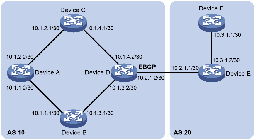
Procedure
1. Enter system view.
system-view
2. Enter OSPF view.
ospf [ process-id | router-id { auto-select | router-id } | vpn-instance vpn-instance-name ] *
3. Configure the router as a stub router.
stub-router [ external-lsa [ max-metric-value ] | include-stub | on-startup { seconds | wait-for-bgp [ seconds ] } | summary-lsa [ max-metric-value ] ] *
By default, the router is not configured as a stub router.
A stub router is not related to a stub area.
Configuring OSPF isolation
About this task
Isolation is a method used for network device maintenance. It gracefully removes a device from the packet forwarding path for maintenance and gracefully adds the device to the network after maintenance.
To reduce impact on traffic forwarding, you can isolate a device before upgrading it. OSPF isolation works as follows:
1. After OSPF isolation is enabled for a device, OSPF increases the link cost in LSAs advertised by the device based on the following rules:
¡ The link cost in Type-1 LSAs (Router LSAs) is increased to 65535.
¡ The link cost in the following LSAs is increased to 16711680:
- Type-3 LSAs (Network summary LSAs).
- Type-5 LSAs (AS external LSAs).
- Type-7 LSAs (NSSA external LSAs).
2. Each neighbor of the device reselects an optimal route based on the LSAs and stops forwarding traffic to the device. The device is fully isolated from the network and you can upgrade the device.
3. After the maintenance, disable OSPF isolation on the device to restore its link cost and gracefully add it back to the network.
Restrictions and guidelines
Both the isolate enable and stub-router external-lsa 16711680 summary-lsa 16711680 include-stub commands can isolate the device from the network.
When you execute both the isolate enable and stub-router commands, follow these restrictions and guidelines:
· When both the isolation feature and the stub router feature take effect, Type-3 LSAs, Type-5 LSAs, and Type-7 LSAs each use the higher one of the two LSA-specific link costs provided by those features.
· If the on-startup keyword is specified in the stub-router command, traffic forwarding path selection is affected only by the isolation feature when the stub router does not take effect.
Procedure
1. Enter system view.
system-view
2. Enter OSPF view.
ospf [ process-id | router-id router-id | vpn-instance vpn-instance-name ] *
3. Configure OSPF isolation.
¡ Enable OSPF isolation to gracefully isolate the device from the network.
isolate enable
¡ Disable OSPF isolation to gracefully add the device back to the network.
undo isolate enable
By default, OSPF isolation is disabled.
Configuring OSPF shutdown
About this task
For maintenance purposes, you can use this feature to shut down OSPF processes on the device with small impact on the network. If you shut down a process, it will perform the following operations:
· Send 1-way hello packets to its neighbors.
On receipt of the packets, the neighbors disconnect from the OSPF process and use the backup path to forward traffic.
· Stop receiving and sending OSPF packets.
· Clear its neighbor, LSDB, and OSPF route information.
After maintenance, you can use the undo shutdown process command to restart the process for neighbor relationship re-establishment.
This feature shuts down an OSPF process while retaining the process-associated settings to facilitate your maintenance.
Procedure
1. Enter system view.
system-view
2. Enter OSPF view.
ospf [ process-id | router-id router-id | vpn-instance vpn-instance-name ] *
3. Configure OSPF shutdown.
¡ Shut down an OSPF process to isolate it from the network.
shutdown process
¡ Restart the OSPF process to add it back to the network.
undo shutdown process
By default, the OSPF process is not shut down.
Enabling compatibility with RFC 1583
About this task
RFC 1583 specifies a different method than RFC 2328 for selecting the optimal route to a destination in another AS. When multiple routes are available to the ASBR, OSPF selects the optimal route by using the following procedure:
1. Selects the route with the highest preference.
¡ If RFC 2328 is compatible with RFC 1583, all these routes have equal preference.
¡ If RFC 2328 is not compatible with RFC 1583, the intra-area route in a non-backbone area is preferred to reduce the burden of the backbone area. The inter-area route and intra-area route in the backbone area have equal preference.
2. Selects the route with the lower cost if two routes have equal preference.
3. Selects the route with the larger originating area ID if two routes have equal cost.
Restrictions and guidelines
To avoid routing loops, set identical RFC 1583-compatibility on all routers in a routing domain.
Procedure
1. Enter system view.
system-view
2. Enter OSPF view.
ospf [ process-id | router-id { auto-select | router-id } | vpn-instance vpn-instance-name ] *
3. Enable compatibility with RFC 1583.
rfc1583 compatible
By default, compatibility with RFC 1583 is enabled.
Configuring OSPF dynamic host name mappings
About this task
OSPF uses a router ID to uniquely identify a router in an AS. The length of router IDs is fixed at 4 bytes. It is inconvenient for the network administrator to memorize the router IDs in dotted decimal notation when verifying the OSPF neighbor relationships, routing tables, and LSDBs.
This task allows you to map a router ID to a host name. The mapping table is maintained by OSPF routers. Host names are more straightforward than router IDs in network maintenance, management, and failure diagnosis.
Restrictions and guidelines
OSPF uses Type-10 LSAs and Type-11 LSAs to carry information about the dynamic host name attribute. Therefore, make sure the opaque LSA reception and advertisement capability is enabled.
Procedure
1. Enter system view.
system-view
2. Enable OSPF, and enter OSPF view.
ospf [ process-id | router-id { auto-select | router-id } | vpn-instance vpn-instance-name ] *
3. Enable the opaque LSA reception and advertisement capability.
opaque-capability enable
By default, the opaque LSA reception and advertisement capability is enabled.
4. Enable the OSPF dynamic host name mapping feature.
hostname [ host-name ]
By default, the OSPF dynamic host name mapping feature is disabled.
Configuring OSPF neighbor flapping suppression
About this task
Neighbor state changes will cause neighbor relationship reestablishment, LSDB synchronization, and route calculation. A large number of packets will be exchanged, which affects stability of existing neighbors and operation of OSPF and relevant services. To resolve this issue, enable OSPF neighbor flapping suppression to delay neighbor relationship establishment or traffic forwarding through neighbor links.
Use this command to avoid frequent flooding and topology changes during neighbor relationship establishment. Before the specified neighbor flapping suppression timer expires, OSPF does not establish neighbor relationships.
The OSPF neighbor flapping suppression mechanism is as follows:
· The interface starts a flapping counter to count neighbor flapping events. When the device detects a neighbor flapping event, it increases the flapping counter by 1.
A neighbor flapping event occurs when the time interval between two consecutive neighbor state changes (from Full to another state) is less than the specified detect interval.
· If the time interval between two consecutive neighbor state changes (from Full to another state) is greater than the specified resume interval, the flapping counter is reset.
· If the flapping counter reaches or exceeds the specified threshold, OSPF starts flapping suppression for all neighbors on the interface.
· During the flapping suppression period, if the device detects another neighbor flapping event, it resets the resume interval.
You can enable OSPF neighbor flapping suppression by executing the suppress-flapping hold-down or ospf peer suppress-flapping hold-max-cost command.
· Use the suppress-flapping hold-down command to avoid frequent flooding and topology changes during neighbor relationship establishment. Before the specified neighbor flapping suppression timer expires, OSPF does not establish neighbor relationships.
· Use the ospf peer suppress-flapping hold-max-cost command to set the cost of all neighbor links to the maximum value 65535 within the neighbor flapping suppression period (resume interval).
OSPF neighbor flapping suppression is disabled when one of the following conditions is met:
· The neighbor flapping suppression timer expires.
· The OSPF process is restarted by using the reset ospf process command.
Restrictions and guidelines
If you execute both the suppress-flapping hold-down and ospf peer suppress-flapping hold-max-cost commands for an interface, the suppress-flapping hold-down command applies first. When neighbor suppression starts, OSPF performs the following operations in sequence:
1. Disables neighbor relationship establishment until the specified suppression timer expires.
2. Allows neighbor relationship establishment and sets the maximum cost for neighbor links until the specified resume interval expires.
3. Resumes the original link cost when the specified resume interval expires.
Procedure
1. Enter system view.
system-view
2. Enter interface view.
interface interface-type interface-number
3. Enable OSPF neighbor flapping suppression. Choose one option as needed:
¡ Enable OSPF neighbor flapping suppression and set the suppression timer.
ospf peer suppress-flapping hold-down interval
¡ Enable OSPF neighbor flapping suppression and set the maximum cost for neighbor links.
ospf peer suppress-flapping hold-max-cost
By default, OSPF neighbor flapping suppression is disabled.
4. Configure detection parameters for OSPF neighbor flapping suppression.
ospf peer suppress-flapping { detect-interval detect-interval | threshold threshold | resume-interval resume-interval } *
By default, the detect interval is 60 seconds, the threshold value is 10, and the resume interval is 120 seconds.
For the ospf peer suppress-flapping hold-max-cost command, the resume interval specifies the suppression period. Before neighbor flapping suppression ends, the suppression period is updated with the resume interval.
Configuring the virtual system feature
About this task
In an AS, each OSPF node has a unique router ID and can manage multiple OSPF interfaces. The IP addresses of the interfaces managed by the same OSPF node cannot reside on the same network segment.
Procedure
1. Enter system view.
system-view
2. Enter OSPF view.
ospf [ process-id | router-id { auto-select | router-id } | vpn-instance vpn-instance-name ] *
3. Enable the virtual system feature for the OSPF process.
virtual-system enable
By default, the virtual system feature is disabled.
4. Return to system view.
quit
5. Enter interface view.
interface interface-type interface-number
6. Enable the virtual system feature on the OSPF interface.
ospf virtual-system router-id router-id
By default, the virtual system feature is disabled.
Configuring OSPF GR
About OSPF GR
GR ensures forwarding continuity when a routing protocol restarts or an active/standby switchover occurs.
Two routers are required to complete a GR process. The following are router roles in a GR process:
· GR restarter—Graceful restarting router. It must have GR capability.
· GR helper—A neighbor of the GR restarter. It helps the GR restarter to complete the GR process.
OSPF GR has the following types:
· IETF GR—Uses Opaque LSAs to implement GR.
· Non-IETF GR—Uses link local signaling (LLS) to advertise GR capability and uses out of band synchronization to synchronize the LSDB.
A device can act as a GR restarter and GR helper at the same time.
Configuring OSPF GR restarter
Configuring the IETF OSPF GR restarter
1. Enter system view.
system-view
2. Enable OSPF and enter its view.
ospf [ process-id | router-id { auto-select | router-id } | vpn-instance vpn-instance-name ] *
3. Enable opaque LSA reception and advertisement capability.
opaque-capability enable
By default, opaque LSA reception and advertisement capability is enabled.
4. Enable the IETF GR.
graceful-restart ietf [ global | planned-only ] *
By default, the IETF GR capability is disabled.
5. (Optional.) Set the GR interval.
graceful-restart interval interval
By default, the GR interval is 120 seconds.
Configuring the non-IETF OSPF GR restarter
1. Enter system view.
system-view
2. Enable OSPF and enter its view.
ospf [ process-id | router-id { auto-select | router-id } | vpn-instance vpn-instance-name ] *
3. Enable the link-local signaling capability.
enable link-local-signaling
By default, the link-local signaling capability is disabled.
4. Enable the out-of-band re-synchronization capability.
enable out-of-band-resynchronization
By default, the out-of-band re-synchronization capability is disabled.
5. Enable non-IETF GR.
graceful-restart [ nonstandard ] [ global | planned-only ] *
By default, non-IETF GR capability is disabled.
6. (Optional.) Set the GR interval.
graceful-restart interval interval
By default, the GR interval is 120 seconds.
Configuring OSPF GR helper
Configuring the IETF OSPF GR helper
1. Enter system view.
system-view
2. Enable OSPF and enter its view.
ospf [ process-id | router-id { auto-select | router-id } | vpn-instance vpn-instance-name ] *
3. Enable opaque LSA reception and advertisement capability.
opaque-capability enable
By default, opaque LSA reception and advertisement capability is enabled.
4. Enable GR helper capability.
graceful-restart helper enable [ planned-only ]
By default, GR helper capability is enabled.
5. (Optional.) Enable strict LSA checking for the GR helper.
graceful-restart helper strict-lsa-checking
By default, strict LSA checking for the GR helper is disabled.
When an LSA change on the GR helper is detected, the GR helper device exits the GR helper mode.
Configuring the non-IETF OSPF GR helper
1. Enter system view.
system-view
2. Enable OSPF and enter its view.
ospf [ process-id | router-id { auto-select | router-id } | vpn-instance vpn-instance-name ] *
3. Enable the link-local signaling capability.
enable link-local-signaling
By default, the link-local signaling capability is disabled.
4. Enable the out-of-band re-synchronization capability.
enable out-of-band-resynchronization
By default, the out-of-band re-synchronization capability is disabled.
5. Enable GR helper.
graceful-restart helper enable
By default, GR helper is enabled.
6. (Optional.) Enable strict LSA checking for the GR helper.
graceful-restart helper strict-lsa-checking
By default, strict LSA checking for the GR helper is disabled.
When an LSA change on the GR helper is detected, the GR helper device exits the GR helper mode.
Triggering OSPF GR
About this task
You can trigger OSPF GR by performing an active/standby switchover or using the reset ospf process command.
Procedure
To trigger OSPF GR, execute the reset ospf [ process-id ] process graceful-restart command in user view.
Configuring BFD for OSPF
About BFD for OSPF
OSPF sends hello packets to neighbors at specific intervals to detect their state. If OSPF does not receive a hello packet from a neighbor within a specific period, OSPF considers the neighbor stale. Such a failure detection method cannot achieve high data reliability, because it takes a long time and causes data loss.
To resolve this issue, configure Bidirectional Forwarding Detection (BFD) for OSPF. This feature improves the route convergence speed against link state changes through fast link state detection. For more information about BFD, see High Availability Configuration Guide.
OSPF supports the following BFD detection modes:
· Bidirectional control detection—Requires BFD configuration to be made on both OSPF routers on the link.
· Single-hop echo detection—Requires BFD configuration to be made on one OSPF router on the link.
Configuring bidirectional control detection
1. Enter system view.
system-view
2. Enter interface view.
interface interface-type interface-number
3. Enable BFD bidirectional control detection.
ospf bfd enable
By default, BFD bidirectional control detection is disabled.
Both ends of a BFD session must be on the same network segment and in the same area.
Configuring single-hop echo detection
1. Enter system view.
system-view
2. (Optional.) Configure the source address of echo packets.
bfd echo-source-ip ip-address
By default, the source address of echo packets is not configured.
As a best practice to avoid network congestion caused by massive ICMP redirect packets from the remote end, execute this command and specify a source IP address that is not on the same network segment as any local interface's IP address.
For more information about this command, see BFD commands in High Availability Command Reference.
3. Enter interface view.
interface interface-type interface-number
4. Enable BFD single-hop echo detection.
ospf bfd enable echo
By default, BFD single-hop echo detection is disabled.
Enabling OSPF to adjust the interface cost according to the BFD session state
About this task
After you enable BFD for OSPF, the OSPF neighbor relationship goes down when the BFD session is down and comes up when the BFD session is up. When the BFD session state changes frequently, OSPF neighbor relationship flapping will occur and traffic forwarding might be affected.
To resolve this issue, enable OSPF to adjust the interface cost according to the BFD session state.
After you configure this feature on an interface, OSPF adjusts the interface cost as follows:
· When the BFD session on the interface goes down, OSPF increases the cost value for the interface.
· When the BFD session on the interface comes up, OSPF restores the cost value for the interface.
Procedure
1. Enter system view.
system-view
2. Enter interface view.
interface interface-type interface-number
3. Enable OSPF to adjust the interface cost according to the BFD session state.
ospf bfd adjust-cost { cost-offset | max }
By default, OSPF does not adjust the link cost according to the BFD session state.
Suppressing interface cost adjustment according to the BFD session state upon BFD session flapping
About this task
After you enable OSPF to adjust the interface cost according to the BFD session state, if BFD session flaps frequently, the following conditions might occur:
· The OSPF interface cost changes frequently, resulting in repeated route calculations that greatly consume device resources.
· When the BFD session state changes from down to up, OSPF immediately resumes the original interface cost. If the link becomes unavailable again in a short time, packet loss will occur on this link before route convergence.
You can configure this feature to address the previous issues. When the BFD session state changes, OSPF performs the following operations instead of immediately adjusting the interface cost:
· When the BFD session state changes from up to down, OSPF starts a BFD session state detection timer, and records one BFD session down event. If the number of BFD session down events crosses the threshold within the detection interval, OSPF adjusts the interface cost based on configuration of the ospf bfd adjust-cost command. (The threshold is specified with the threshold keyword. The detection interval is specified with the detect-interval argument.) If this condition is not met, OSPF does not adjust the interface cost.
· After OSPF adjusts the interface cost (based on the configuration of the ospf bfd adjust-cost command), it starts a delay timer when the BFD session state changes from down to up. Before expiration of the delay timer (specified with the resume-interval argument), the following conditions will occur:
¡ If the BFD session remains up, OSPF resumes the original interface cost when the delay timer expires.
¡ If the BFD session state changes from up to down, OSPF deletes the delay timer and does not resume the original interface cost.
Restrictions and guidelines
This command takes effect only after you configure the ospf bfd adjust-cost command.
Procedure
1. Enter system view.
system-view
2. Enter interface view.
interface interface-type interface-number
3. Suppress adjustment of the interface cost according to the BFD session state upon BFD session flapping.
ospf bfd adjust-cost suppress-flapping { detect-interval detect-interval | resume-interval resume-interval | threshold threshold } *
By default, OSPF does not suppress adjustment of the interface cost according to the BFD session state upon BFD session flapping.
Configuring OSPF FRR
About OSPF FRR
OSPF Fast Reroute (FRR) calculates a backup path based on the LSDB or specifies a backup path by using a routing policy. Then, it saves the backup path information to the FIB. When the primary path fails, the system immediately switches traffic to the backup path to prevent traffic loss and reduce the route convergence time.
OSPF supports Loop Free Alternate (LFA) FRR and remote LFA FRR.
The following OSPF FRR traffic protection types are available:
· Link protection—Protects traffic that traverses a specific link.
· Node protection—Protects traffic that traverses a specific node.
Node protection takes precedence over link protection.
Restrictions and guidelines for OSPF FRR
If both OSPF FRR and PIC are configured, OSPF FRR takes effect.
OSPF FRR tasks at a glance
To configure OSPF FRR, perform the following tasks:
1. Configuring an OSPF backup path
Perform a minimum of one task.
¡ Configuring OSPF remote LFA FRR
¡ Configuring OSPF FRR to use a backup next hop specified in a routing policy
2. (Optional.) Setting the priority for FRR backup path selection policies
3. (Optional.) Configuring BFD for OSPF FRR
¡ Configuring BFD control packet mode for OSPF FRR
¡ Configuring BFD echo packet mode for OSPF FRR
Configuring OSPF LFA FRR
About this task
A link or router failure on a path can cause packet loss until OSPF completes routing convergence based on the new network topology. FRR enables fast rerouting to minimize the impact of link or node failures.
Figure 39 Network diagram for OSPF FRR
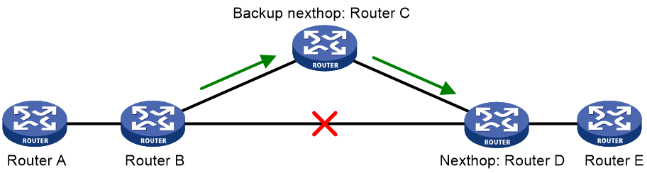
As shown in Figure 39, configure OSPF FRR on Router B to calculate a backup next hop by using the LFA algorithm. When the primary link fails, OSPF directs packets to the backup next hop. At the same time, OSPF calculates the shortest path based on the new network topology. It forwards packets over the path after network convergence.
OSPF ECMP FRR
In ECMP scenarios, you can configure OSPF to calculate a backup next hop separately for each ECMP route with the LFA algorithm. ECMP routes might not share the same backup next hop.
As shown in Figure 40, the source node Device A forwards traffic to the destination node Device D. Traffic is load balanced among Link 1, Link 2, and Link 3.
· With ECMP FRR disabled, OSPF does not calculate a backup next hop separately for Link 1, Link 2, and Link 3. When Link 1 fails, traffic previously forwarded through Link 1 is randomly switched to Link 2 or Link 3. This does not facilitate service traffic management.
· With ECMP FRR enabled, OSPF calculates a backup next hop separately for Link 1, Link 2, and Link 3. For example, if the backup next hop for Link 1 is Device C, when Link 1 fails, traffic previously forwarded through Link 1 is switched to backup next hop Device C. This facilitates service traffic management.
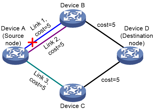
OSPF ECMP-shared FRR
In ECMP scenarios, you can configure OSPF to calculate a backup next hop for ECMP routes with the LFA algorithm. ECMP routes share the same backup next hop.
As shown in Figure 41, the source node Device A forwards traffic to the destination node Device D. Traffic is load balanced between Link 1 and Link 2. ECMP-shared FRR operates as follows:
· With ECMP-shared FRR disabled, OSPF does not calculate any backup next hop for Link 1 or Link 2. When Device B fails, Link 1 and Link 2 both fail, causing traffic disruption before routing convergence.
· With ECMP-shared FRR enabled, OSPF calculates a backup next hop for Link 1 and Link 2. If Device B fails, traffic is switched to the backup next hop Device C, preventing traffic disruption.
Figure 41 OSPF ECMP-shared FRR
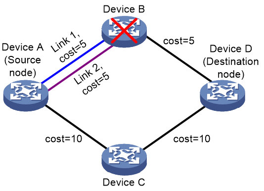
Procedure
1. Enter system view.
system-view
2. Enter interface view.
interface interface-type interface-number
3. (Optional.) Enable LFA on an interface.
ospf fast-reroute lfa-backup
By default, the interface is enabled with LFA and it can be selected as a backup interface.
4. Return to system view.
quit
5. Enter OSPF view.
ospf [ process-id | router-id { auto-select | router-id } | vpn-instance vpn-instance-name ] *
6. Enable OSPF FRR to use the LFA algorithm to calculate a backup next hop.
fast-reroute lfa [ abr-only | ecmp-frr | ecmp-shared ]
By default, OSPF FRR is disabled.
If abr-only is specified, the route to the ABR is selected as the backup path.
Configuring OSPF remote LFA FRR
About this task
In a network topology where OSPF LFA FRR cannot calculate the backup path, configure remote LFA FRR to ensure network reliability.
Remote LFA uses the following concepts:
· P space—Use the source node of the protected link as the root to establish a shortest path tree. All nodes that are reachable from the source node without passing the protected link form the P space. Nodes in the P space are called P nodes.
· Extended P space—Use the source node of the protected link and its neighbors as the roots to establish shortest path trees. All nodes that are reachable from the source node or one of its neighbors without passing the protected link form the extended P space. The P space is a subset of the extended P space.
· Q space—Use the destination node of the protected link as the root to establish a reverse shortest path tree. All nodes that are reachable from the root node without passing the protected link form the Q space. Nodes in the Q space are called Q nodes.
· PQ node—A PQ node refers to a node that resides in both the extended P space and the Q space. Remote LFA uses a PQ node as the destination node of a protected link.
As shown in Figure 42, the traffic forwarding path is PE 1—P 1—P 2—PE 2. To avoid traffic loss caused by link failures between P 1 and P 2, the system establishes an LDP tunnel between P 1 and P 4, which is the PQ node. When the link between P 1 and P 2 fails, P 1 encapsulates IP packets in MPLS packets and sends the MPLS packets to P 4 through the LDP tunnel. After receiving the MPLS packets, P 4 removes the MPLS labels of the packets and then forwards the packets to the next hop based on the IP routing table.
The system determines P 4 as the PQ node as follows:
1. Uses P 1 (source node of the protected link) and its neighbors except P 2 (which passes the protected link) as the roots to establish shortest path trees.
2. Finds out all nodes that are reachable from P 1 or one of its neighbors without passing the protected link, which are PE 1, P 1, P 3, and P 4.
These nodes form the extended P space.
3. Uses P 2 (destination node of the protected link) as the root to establish a reverse shortest path tree.
4. Finds out all nodes that are reachable from P 2 without passing the protected link, which are PE 2 and P 4.
These nodes form the Q space.
5. Finds out all nodes that reside in both the extended P space and the Q space.
Only P 4 resides in both the extended P space and the Q space, so P 4 is the PQ node of the protected link.
Figure 42 Network diagram for OSPF remote LFA FRR
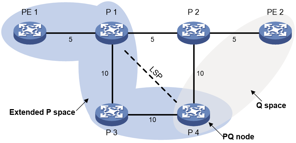
Prerequisites
Enable MPLS and MPLS LDP on all nodes and interfaces participating in MPLS forwarding. For more information, see basic MPLS configuration and LDP configuration in MPLS Configuration Guide.
Procedure
1. Enter system view.
system-view
2. Enter OSPF view.
ospf [ process-id | router-id { auto-select | router-id } | vpn-instance vpn-instance-name ] *
3. Enable OSPF remote LFA FRR.
fast-reroute remote-lfa tunnel ldp
By default, OSPF remote LFA FRR is disabled.
4. (Optional.) Set the maximum cost from the source node of a protected link to a PQ node.
fast-reroute remote-lfa maximum-cost cost
By default, the maximum cost from the source node of a protected link to a PQ node is 4294967295.
5. (Optional.) Specify a prefix list to filter PQ nodes.
fast-reroute remote-lfa prefix-list prefix-list-name
By default, no prefix list is specified to filter PQ nodes. Any PQ node can be selected as the backup next hop.
Multiple PQ nodes might reach the source node of a specific protected link. You can use this command to specify a prefix list to filter PQ nodes.
6. (Optional.) Disable remote LFA calculation on an interface.
a. Return to system view.
quit
b. Enter interface view.
interface interface-type interface-number
c. Disable remote LFA calculation on the interface.
ospf fast-reroute remote-lfa disable
By default, remote LFA calculation is enabled on the interface.
Configuring OSPF FRR to use a backup next hop specified in a routing policy
About this task
Before you perform this task, use the apply fast-reroute backup-interface command to specify a backup next hop in a routing policy for OSPF FRR. For more information about the apply fast-reroute backup-interface command and routing policy configuration, see "Configuring routing policies."
Procedure
1. Enter system view.
system-view
2. Enter OSPF view.
ospf [ process-id | router-id { auto-select | router-id } | vpn-instance vpn-instance-name ] *
3. Enable OSPF FRR to use a backup next hop specified in a routing policy.
fast-reroute route-policy route-policy-name
By default, OSPF FRR is disabled.
Setting the priority for FRR backup path selection policies
About this task
OSPF FRR uses specific policies for backup path calculation. This command defines the priority for the backup path selection policy. The higher the value, the higher the priority of the associated backup path selection policy. Changing the backup path selection policy priority can affect the backup path calculation result for OSPF FRR. The backup paths can provide node protection or link protection for traffic, or provide both node protection and link protection.
OSPF FRR supports the following backup path selection policies that are used to generate different topologies for backup path calculation:
· Node protection—OSPF FRR performs backup path calculation after excluding the primary next hop node.
· Lowest cost—OSPF FRR performs backup path calculation after excluding the direct primary link.
· SRLG disjoint—When one link in the SRLG fails, the other links in the SRLG might also fail. If you use a link in this SRLG as the backup link for the faulty link, protection does not take effect. To avoid this issue, OSPF FRR excludes the local links in the same SRLG as the direct primary link and then performs backup path calculation.
For OSPF FRR, the SRLG disjoint policy depends on the node protection and lowest cost policies.
If multiple backup path selection policies exist in an OSPF process, the policy with the highest priority is used to calculate the backup path. If the policy fails to calculate the backup path, the policy with the highest priority in the remaining policies is used. OSPF performs backup path calculation by using the node protection and lowest cost policies as follows:
· If the node protection policy has higher priority and fails to calculate the backup path, OSPF uses the lowest cost policy to calculate the backup path. If the lowest cost policy still fails to calculate the backup path, reliability cannot be ensured upon primary link failure.
· If the lowest cost policy has higher priority and fails to calculate the backup path, OSPF does not perform further backup path calculation with the node protection policy. Reliability cannot be ensured upon primary link failure.
Table 21 shows the backup path selection mechanism for OSPF FRR based on priorities of backup path selection policies.
Table 21 Backup path selection mechanism for OSPF FRR based on priorities of link selection policies
|
Priorities of link selection policies |
Backup path selection mechanism for OSPF FRR |
|
Node protection > lowest cost > SRLG disjoint |
OSPF FRR performs calculations based on the node protection and lowest cost policies in descending order of priority. OSPF FRR performs a maximum of two calculations. If OSPF FRR calculates a backup path with a link selection policy, it does not perform further calculations. |
|
Node protection > SRLG disjoint > lowest cost |
OSPF FRR performs calculations based on the node protection, node protection + SRLG disjoint, lowest cost + SRLG disjoint, and lowest cost policies in descending order of priority. OSPF FRR performs a maximum of four calculations. If OSPF FRR calculates a backup path with a link selection policy, it does not perform further calculations. |
|
SRLG disjoint > node protection > lowest cost |
OSPF FRR performs calculations based on the node protection + SRLG disjoint, lowest cost + SRLG disjoint, node protection, and lowest cost policies in descending order of priority. OSPF FRR performs a maximum of four calculations. If OSPF FRR calculates a backup path with a link selection policy, it does not perform further calculations. |
|
Lowest cost > node protection > SRLG disjoint |
OSPF FRR performs calculations based on the lowest cost policy. OSPF FRR performs only one calculation. |
|
Lowest cost > SRLG disjoint > node protection |
OSPF FRR performs calculations based on the lowest cost policy. OSPF FRR performs only one calculation. |
|
SRLG disjoint > lowest cost > node protection |
OSPF FRR performs calculations based on the node protection + SRLG disjoint, lowest cost + SRLG disjoint, and lowest cost policies in descending order of priority. OSPF FRR performs a maximum of three calculations. If OSPF FRR calculates a backup path with a link selection policy, it does not perform further calculations. |
In a multi-active and multi-backup scenario, multiple load balancing paths exist between the source node and the destination node. You can enable OSPF FRR to calculate a backup path separately for each load balancing path. By default, OSPF FRR preferentially selects the path with the lowest cost as the backup path when it uses the node protection or lowest cost policy for backup path calculation. OSPF FRR does not identify whether the selected backup path is a load balancing path, except in the following situations:
· OSPF FRR uses the node protection policy to calculate backup paths. Only if the non-ECMP policy takes precedence over the node protection policy, OSPF FRR prefers non-load-balancing paths during backup path selection. If no non-load-balancing path exists, OSPF FRR selects a load balancing path as the backup path. If the lowest cost policy fails to calculate the backup path, OSPF FRR uses the lowest cost policy for further calculation.
· OSPF FRR uses the lowest cost policy to calculate backup paths. Only if the non-ECMP policy takes precedence over the lowest cost policy, OSPF FRR prefers non-load-balancing paths during backup path selection. If no non-load-balancing path exists, OSPF FRR selects a load balancing path as the backup path. If the lowest cost policy fails to calculate the backup path, OSPF FRR does not use the node protection policy to calculate backup paths.
OSPF FRR uses different backup path selection policies to select the backup path as follows:
· Node protection policy.
As shown in Figure 43, Device A uses the node protection policy and selects path Device A->Device B->Device D as the backup path.
Figure 43 Node protection backup path selection
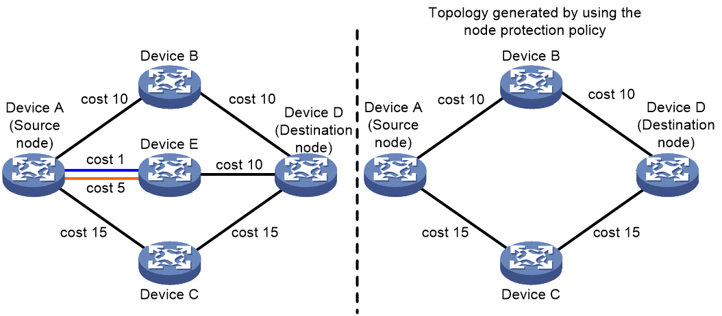
· Lowest cost policy.
As shown in Figure 44, Device A uses the lowest cost policy and selects path Device A->Device E->Device D as the backup path.
Figure 44 Lowest cost backup path selection

· Node protection and SRLG disjoint policies.
As shown in Figure 45, Device A uses the node protection and SRLG disjoint policies and selects path Device A->Device B->Device D as the backup path.
Figure 45 SRLG disjoint backup path selection
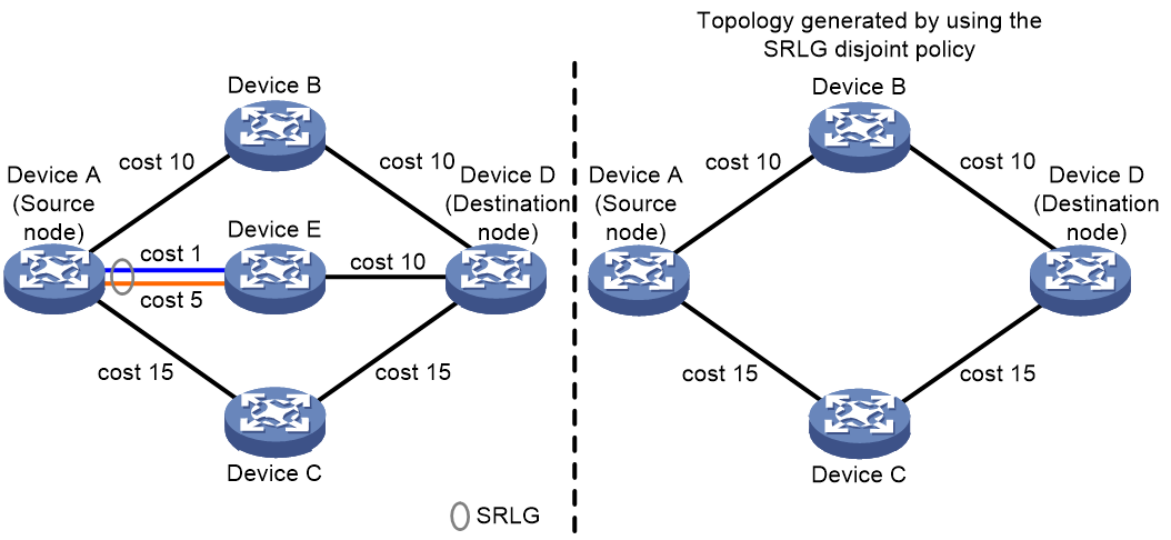
Restrictions and guidelines
When you configure multiple backup path selection policies for an OSPF process, OSPF first uses the policy with the highest priority to calculate a backup path. If the backup path calculation fails, OSPF works as follows:
· If the SRLG disjoint policy has the highest priority but the backup path calculation fails, OSPF selects the one with the higher priority from the node protection and lowest cost policies:
¡ If the node protection policy has the higher priority but the backup path calculation still fails, OSPF uses the lowest cost policy for further calculation.
¡ If the lowest cost policy has the higher priority but the backup path calculation still fails, OSPF does not perform further backup path calculation.
· If the node protection policy has the highest priority but the backup path calculation fails, OSPF selects the one with the higher priority from the SRLG disjoint and lowest cost policies:
¡ If the SRLG disjoint policy has the higher priority but the backup path calculation still fails, OSPF uses the lowest cost policy for further calculation.
¡ If the lowest cost policy has the higher priority but the backup path calculation still fails, OSPF does not perform further backup path calculation.
· If the lowest cost policy has the highest priority but the backup path calculation fails, OSPF does not perform further backup path calculation.
Procedure
1. Enter system view.
system-view
2. Enter OSPF view.
ospf [ process-id | router-id { auto-select | router-id } | vpn-instance vpn-instance-name ] *
3. Set the priority for the node protection, lowest cost, non-ECMP, or SRLG disjoint backup path selection policy.
fast-reroute tiebreaker { lowest-cost | node-protecting | non-ecmp | srlg-disjoint } preference preference
By default, the priority values of the node protection, lowest cost, non-ECMP, and SRLG disjoint backup path selection policies are 40, 20, 15, and 10, respectively.
Configuring BFD control packet mode for OSPF FRR
About this task
By default, OSPF FRR does not use BFD to detect primary link failures. To speed up OSPF convergence, enable BFD control packet mode for OSPF FRR to detect primary link failures. This mode requires BFD configuration on both OSPF routers on the link.
Procedure
1. Enter system view.
system-view
2. Enter interface view.
interface interface-type interface-number
3. Enable BFD control packet mode for OSPF FRR.
ospf primary-path-detect bfd ctrl
By default, BFD control packet mode is disabled for OSPF FRR.
Configuring BFD echo packet mode for OSPF FRR
About this task
By default, OSPF FRR does not use BFD to detect primary link failures. To speed up OSPF convergence, enable BFD echo packet mode for OSPF FRR to detect primary link failures. This mode requires BFD configuration on one OSPF router on the link.
Procedure
1. Enter system view.
system-view
2. Configure the source IP address of BFD echo packets.
bfd echo-source-ip ip-address
By default, the source IP address of BFD echo packets is not configured.
As a best practice to avoid network congestion caused by massive ICMP redirect packets from the remote end, execute this command and specify a source IP address that is not on the same network segment as any local interface's IP address.
For more information about this command, see High Availability Command Reference.
3. Enter interface view.
interface interface-type interface-number
4. Enable BFD echo packet mode for OSPF FRR.
ospf primary-path-detect bfd echo
By default, BFD echo packet mode is disabled for OSPF FRR.
Enabling OSPF to adjust the interface cost according to the link quality
About this task
If the device forwards OSPF packets along low-quality links, slow packet transmission and packet loss might occur. To minimize the impact of low-quality links on the OSPF network, you can enable OSPF to adjust the interface cost according to the link quality.
The following items affect the quality level of links:
· Error codes—Error codes refer to bit differences between the received and source signals, cannot be avoided because of inevitable link aging and optical path jitter problems. A high error code ratio might cause service degradation or interruption. The link quality detection module adjusts the quality level of links based on the bit error ratio. For more information about bit errors, see error code detection configuration in High Availability Configuration Guide.
· Card health—The health of a card is downgraded when the card fails. The link quality detection module adjusts the quality level of links based on the card health. For more information about hardware failure detection, see device management configuration in Fundamentals Configuration Guide.
After you perform this task on an interface, OSPF adjusts the interface cost as follows:
· When the link quality detection module detects that the link quality of the interface becomes poor, the module performs the following operations:
¡ Changes the link quality level from GOOD to LOW.
¡ Reports an error code event to the OSPF module.
Upon receiving the error code event, OSPF increases the cost value for the interface.
· When the link quality detection module detects that the link quality of the interface restores to GOOD, the module performs the following operations:
¡ Changes the link quality level from LOW to GOOD.
¡ Reports an error code clearing event to the OSPF module.
Upon receiving the error code clearing event, OSPF restores the cost value for the interface to the original value.
This interface cost adjustment mechanism enables OSPF to select good-quality forwarding links, minimizing the impact of low-quality links on the OSPF network.
Restrictions and guidelines
This feature affects the route selection results on only one side, because it only adjusts the cost values for interfaces on the local device.
Procedure
1. Enter system view.
system-view
2. Enter interface view.
interface interface-type interface-number
3. Enable OSPF to adjust the link cost according to the link quality.
ospf link-quality adjust-cost { cost-offset | max }
OSPF adjusts the link cost according to the link quality.
Configuring OSPF authentication
About OSPF area and interface authentication
Perform this task to configure OSPF area and interface authentication.
OSPF adds the configured key into sent packets, and uses the key to authenticate received packets. Only packets that pass the authentication can be received. If a packet fails the authentication, the OSPF neighbor relationship cannot be established.
If you configure OSPF authentication for both an area and an interface in that area, the interface uses the OSPF authentication configured on it.
Configuring OSPF area authentication
1. Enter system view.
system-view
2. Enter OSPF view.
ospf [ process-id | router-id { auto-select | router-id } | vpn-instance vpn-instance-name ] *
3. Enter area view.
area area-id
4. Configure area authentication mode.
¡ Configure MD5/HMAC-MD5/HMAC-SHA-256 authentication.
authentication-mode { hmac-md5 | hmac-sha-256 | md5 } key-id { cipher | plain } string
¡ Configure simple authentication.
authentication-mode simple { cipher | plain } string
¡ Configure keychain authentication.
authentication-mode keychain keychain-name
For information about keychains, see Security Configuration Guide.
By default, no authentication is configured.
You must configure the same authentication mode and key on all the routers in an area.
Configuring OSPF interface authentication
1. Enter system view.
system-view
2. Enter interface view.
interface interface-type interface-number
3. Configure interface authentication mode.
¡ Configure simple authentication.
ospf authentication-mode simple { cipher | plain } string
¡ Configure MD5/HMAC-MD5/HMAC-SHA-256 authentication.
ospf authentication-mode { hmac-md5 | hmac-sha-256 | md5 } key-id { cipher | plain } string
¡ Configure keychain authentication.
ospf authentication-mode keychain keychain-name
For information about keychains, see Security Configuration Guide.
By default, no authentication is configured.
You must configure the same authentication mode and key on both the local interface and its peer interface.
Configuring GTSM for OSPF
About GTSM
The Generalized TTL Security Mechanism (GTSM) protects the device by comparing the TTL value in the IP header of incoming OSPF packets against a valid TTL range. If the TTL value is within the valid TTL range, the packet is accepted. If not, the packet is discarded.
The valid TTL range is from 255 – the configured hop count + 1 to 255.
Restrictions and guidelines for GTSM
To use GTSM, you must configure GTSM on both the local and peer devices. You can specify different hop-count values for them.
The configuration in OSPF area view applies to all OSPF interfaces in the area. The configuration in interface view takes precedence over the configuration in OSPF area view.
GTSM checks OSPF packets from common neighbors and virtual link neighbors. It does not check OSPF packets from sham link neighbors. For information about GTSM for OSPF sham links, see MPLS L3VPN configuration in MPLS Configuration Guide.
Configuring GTSM in OSPF area view
1. Enter system view.
system-view
2. Enter OSPF view.
ospf [ process-id | router-id { auto-select | router-id } | vpn-instance vpn-instance-name ] *
3. Enter OSPF area view.
area area-id
4. Enable GTSM for the OSPF area.
ttl-security [ hops hop-count ]
By default, GTSM is disabled for the OSPF area.
Editing the hop limit clears GTSM discarded packet statistics.
Configuring GTSM in interface view
1. Enter system view.
system-view
2. Enter interface view.
interface interface-type interface-number
3. Configure GTSM for the interface.
¡ Enable GTSM for the interface.
ospf ttl-security [ hops hop-count ]
¡ Disable GTSM for the interface.
ospf ttl-security disable
Disable GTSM for an interface when the following conditions exist:
- The area to which the interface belongs is enabled with GTSM.
- The neighbor of the interface does not support GTSM.
By default, an interface uses the GTSM configuration of the area to which the interface belongs.
Editing the hop limit clears GTSM discarded packet statistics on the interface.
Configuring OSPF multi-area adjacency
Enabling OSPF on a multi-area adjacency interface
About this task
According to OSPF protocols, intra-area paths have higher priority than inter-area paths. Assume an area contains a high-speed link. Devices in other areas cannot use it for data transmission, because the interface belongs to only one area. To address this issue, perform this task.
Procedure
1. Enter system view.
system-view
2. Enter interface view.
interface interface-type interface-number
3. Enable OSPF on the multi-area adjacent interface.
ospf multi-area area-id
By default, OSPF is not enabled on a multi-area adjacency interface.
Setting the OSPF cost on a multi-area adjacency interface
About this task
Perform this task to manually set a cost for a multi-area adjacency interface. If you do not configure this command, the interface calculates its OSPF cost according to the interface bandwidth.
Procedure
1. Enter system view.
system-view
2. Enter interface view.
interface interface-type interface-number
3. Enable OSPF on the multi-area adjacent interface.
ospf multi-area area-id
By default, OSPF is not enabled on a multi-area adjacency interface.
4. Enable OSPF to adjust the interface cost according to the link quality and set the value to be added to the interface cost.
ospf multi-area area-id cost cost-value
By default, a multi-area adjacency interface calculates its OSPF cost according to the interface bandwidth.
Setting the authentication mode and key on a multi-area adjacency interface
About this task
On networks with high security requirements, use this command to configure OSPF interface authentication.
Procedure
1. Enter system view.
system-view
2. Enter interface view.
interface interface-type interface-number
3. Enable OSPF on interfaces adjacent to multiple areas.
ospf multi-area area-id
By default, OSPF is not enabled on a multi-area adjacency interface.
4. Set the authentication mode on a multi-area adjacency interface. Choose one as needed:
¡ Configure MD5/HMAC-MD5/HMAC-SHA-256 authentication.
ospf multi-area area-id authentication-mode { hmac-md5 | hmac-sha-256 | md5 } key-id { cipher | plain } string
¡ Configure simple authentication.
ospf multi-area area-id authentication-mode simple { cipher | plain } string
¡ Configure keychain authentication.
ospf multi-area area-id authentication-mode keychain keychain-name
For more information about keychains, see keychain commands in Security Configuration Guide.
By default, no authentication is configured on a multi-area adjacency interface.
Configuring fast convergence for a multi-area adjacent interface
About this task
Perform this task to configure fast convergence for a multi-area adjacency interface, enhancing network performance.
Setting the hello interval
1. Enter system view.
system-view
2. Enter interface view.
interface interface-type interface-number
3. Enable OSPF on the multi-area adjacent interface.
ospf multi-area area-id
By default, OSPF is not enabled on a multi-area adjacency interface.
4. Set the hello interval.
ospf multi-area area-id timer hello seconds
By default, the hello interval is 10 seconds on a multi-area adjacency interface.
Setting the dead interval
1. Enter system view.
system-view
2. Enter interface view.
interface interface-type interface-number
3. Enable OSPF on the multi-area adjacent interface.
ospf multi-area area-id
By default, OSPF is not enabled on a multi-area adjacency interface.
4. Set the dead interval.
ospf multi-area area-id timer dead seconds
By default, the dead interval is 40 seconds on a multi-area adjacency interface.
The dead interval must be a minimum of four times the hello interval on an interface.
Setting the LSA retransmission interval on a multi-area adjacency interface
1. Enter system view.
system-view
2. Enter interface view.
interface interface-type interface-number
3. Enable OSPF on the multi-area adjacent interface.
ospf multi-area area-id
By default, OSPF is not enabled on a multi-area adjacency interface.
4. Set the LSA retransmission interval on the multi-area adjacency interface.
ospf multi-area area-id timer retransmit seconds
By default, the LSA retransmission interval is 5 seconds on a multi-area adjacency interface.
A retransmission interval setting that is too small can cause unnecessary LSA retransmissions. Typically set a bigger interval than the round-trip time of a packet between two neighbors.
Setting the LSA transmission delay on a multi-area adjacency interface
1. Enter system view.
system-view
2. Enter interface view.
interface interface-type interface-number
3. Enable OSPF on the multi-area adjacent interface.
ospf multi-area area-id
By default, OSPF is not enabled on a multi-area adjacency interface.
4. Set the LSA transmission delay on the multi-area adjacency interface.
ospf multi-area area-id trans-delay seconds
By default, the LSA retransmission interval is 5 seconds on a multi-area adjacency interface.
Enabling OSPF to adjust the cost of a multi-area adjacency interface according to the link quality
1. Enter system view.
system-view
2. Enter interface view.
interface interface-type interface-number
3. Enable OSPF on the multi-area adjacent interface.
ospf multi-area area-id
By default, OSPF is not enabled on a multi-area adjacency interface.
4. Enable OSPF to adjust the cost of the multi-area adjacency interface according to the link quality.
ospf multi-area area-id link-quality adjust-cost { cost-offset | max }
By default, OSPF does not adjust the multi-area adjacency interface cost according to the link quality.
Enabling a multi-area adjacency interface to add its MTU into DD packets
Restrictions and guidelines
Perform this task with caution, because it will cause OSPF to re-establish neighbor relationships.
Procedure
1. Enter system view.
system-view
2. Enter interface view.
interface interface-type interface-number
3. Enable OSPF on the multi-area adjacent interface.
ospf multi-area area-id
By default, OSPF is not enabled on a multi-area adjacency interface.
4. Enable the multi-area adjacency interface to add its MTU into DD packets.
ospf multi-area area-id mtu-enable
By default, the MTU in DD packets sent from a multi-area adjacency interface is 0.
Setting the maximum length of OSPF packets that can be sent by a multi-area adjacency interface
1. Enter system view.
system-view
2. Enter interface view.
interface interface-type interface-number
3. Enable OSPF on the multi-area adjacent interface.
ospf multi-area area-id
By default, OSPF is not enabled on a multi-area adjacency interface.
4. Setting the maximum length of OSPF packets that can be sent by the multi-area adjacency interface.
ospf multi-area area-id packet-size value
By default, the maximum length of OSPF packets that a multi-area adjacency interface can send equals the interface's MTU.
Configuring OSPF logging and SNMP notifications
Logging neighbor state changes
About this task
Perform this task to enable output of neighbor state change logs to the information center. The information center processes the logs according to user-defined output rules (whether and where to output logs). For more information about the information center, see Network Management and Monitoring Configuration Guide.
Procedure
1. Enter system view.
system-view
2. Enter OSPF view.
ospf [ process-id | router-id { auto-select | router-id } | vpn-instance vpn-instance-name ] *
3. Enable the logging of neighbor state changes.
log-peer-change
By default, this feature of logging neighbor state changes is enabled.
Configuring the OSPF logging feature
About this task
OSPF logs include received and sent hello packet logs, LSA aging logs, route calculation logs, neighbor logs, OSPF route logs, and self-originated and received LSA logs.
Procedure
1. Enter system view.
system-view
2. Enter OSPF view.
ospf [ process-id | router-id { auto-select | router-id } | vpn-instance vpn-instance-name ] *
3. Configure the OSPF logging feature.
event-log { hello { received [ abnormal | dropped ] | sent [ abnormal | failed ] } | lsa-flush | peer | route | spf } size count
event-log lsa-history { asbr | ase | include-duplicate | link-state-id | network | nssa | opaque-area | opaque-as | opaque-link | originate-router advertising-router-id | router | size count | summary | verbose } *
By default, the device can generate a maximum of 100 OSPF logs for each type.
Configuring OSPF network management
About this task
This task involves the following configurations:
· Bind an OSPF process to MIB so that you can use network management software to manage the specified OSPF process.
· Enable SNMP notifications for OSPF to report important events.
· Configure the SNMP notification output interval and the maximum number of SNMP notifications that can be output at each interval.
To report critical OSPF events to an NMS, enable SNMP notifications for OSPF. For SNMP notifications to be sent correctly, you must also configure SNMP on the device. For more information about SNMP configuration, see the network management and monitoring configuration guide for the device.
Procedure
1. Enter system view.
system-view
2. Bind MIB to an OSPF process.
ospf mib-binding process-id
By default, MIB is bound to the process with the smallest process ID.
3. Enable SNMP notifications for OSPF.
snmp-agent trap enable ospf [ authentication-failure | bad-packet | config-error | dr-ip-address-conflict | grhelper-status-change | grrestarter-status-change | if-state-change | intra-area-router-id-conflict | lsa-maxage | lsa-originate | lsdb-approaching-overflow | lsdb-overflow | neighbor-state-change | nssatranslator-status-change | peer-flapping-suppress-status-change | retransmit | sr-prefix-sid-conflict | sr-prefix-sid-conflict-clear | virt-authentication-failure | virt-bad-packet | virt-config-error | virt-retransmit | virtgrhelper-status-change | virtif-state-change | virtneighbor-state-change ] *
By default, SNMP notifications for OSPF are enabled.
4. (Optional.) Extend the format of SNMP notifications for neighbor state changes.
snmp-agent trap ospf neighbor-state-change extended
By default, OSPF does not extend the format of SNMP notifications for neighbor state changes.
5. Enter OSPF view.
ospf [ process-id | router-id { auto-select | router-id } | vpn-instance vpn-instance-name ] *
6. Configure the SNMP notification output interval and the maximum number of SNMP notifications that can be output at each interval.
snmp trap rate-limit interval trap-interval count trap-number
By default, OSPF outputs a maximum of seven SNMP notifications within 10 seconds.
Setting the maximum number of OSPF neighbor relationship troubleshooting entries
1. Enter system view.
system-view
2. Set the maximum number of OSPF neighbor relationship troubleshooting entries.
ospf troubleshooting max-number number
By default, OSPF can record a maximum of 100 neighbor relationship troubleshooting entries.
Display and maintenance commands for OSPF
Execute display commands in any view and reset commands in user view.
|
Task |
Command |
|
Display OSPF process information. |
display ospf [ process-id ] [ verbose ] |
|
Display OSPF GR information. |
display ospf [ process-id ] graceful-restart [ verbose ] |
|
Display OSPF FRR backup next hop information. |
display ospf [ process-id ] [ area area-id ] fast-reroute lfa-candidate |
|
Display OSPF LSDB information. |
display ospf [ process-id ] lsdb [ brief | originate-router advertising-router-id | self-originate ] [ age { max-value max-age-value | min-value min-age-value } * ] [ resolve-hostname ] display ospf [ process-id ] lsdb hostname host-name [ age { max-value max-age-value | min-value min-age-value } * ] display ospf [ process-id ] lsdb opaque-as [ link-state-id ] [ originate-router advertising-router-id | self-originate ] [ age { max-value max-age-value | min-value min-age-value } * ] [ resolve-hostname ] display ospf [ process-id ] lsdb opaque-as [ link-state-id ] hostname host-name [ age { max-value max-age-value | min-value min-age-value } * ] display ospf [ process-id ] lsdb ase [ link-state-id ] [ originate-router advertising-router-id | self-originate ] [ age { max-value max-age-value | min-value min-age-value } * ] [ resolve-hostname ] display ospf [ process-id ] lsdb ase [ link-state-id ] hostname host-name [ age { max-value max-age-value | min-value min-age-value } * ] display ospf [ process-id ] [ area area-id ] lsdb { network | opaque-area | opaque-link } [ link-state-id ] [ originate-router advertising-router-id | self-originate ] [ age { max-value max-age-value | min-value min-age-value } * ] [ resolve-hostname ] display ospf [ process-id ] [ area area-id ] lsdb { network | opaque-area | opaque-link } [ link-state-id ] hostname host-name [ age { max-value max-age-value | min-value min-age-value } * ] display ospf [ process-id ] [ area area-id ] lsdb { asbr | nssa | router | summary } [ link-state-id ] [ originate-router advertising-router-id | self-originate ] [ age { max-value max-age-value | min-value min-age-value } * ] [ resolve-hostname ] display ospf [ process-id ] [ area area-id ] lsdb { asbr | nssa | router | summary } [ link-state-id ] hostname host-name [ age { max-value max-age-value | min-value min-age-value } * ] |
|
Display OSPF next hop information. |
display ospf [ process-id ] nexthop |
|
Display OSPF NSR information. |
display ospf [ process-id ] non-stop-routing status |
|
Display OSPF neighbor information. |
display ospf [ process-id ] peer [ hello | verbose ] [ interface-type interface-number ] [ [ neighbor-id ] [ resolve-hostname ] | hostname host-name ] |
|
Display neighbor statistics for OSPF areas. |
display ospf [ process-id ] peer statistics |
|
Display OSPF routing table information. |
display ospf [ process-id ] routing [ ip-address { mask-length | mask } | priority { critical | high | low | medium } ] [ interface interface-type interface-number ] [ nexthop nexthop-address ] [ verbose ] |
|
Display OSPF shortest path tree information. |
display ospf [ process-id ] [ area area-id ] spf-tree [ verbose ] |
|
Display OSPF statistics. |
display ospf [ process-id ] statistics [ error | packet [ hello | interface-type interface-number ] ] |
|
Display OSPF virtual link information. |
display ospf [ process-id ] vlink |
|
Display OSPF request queue information. |
display ospf [ process-id ] request-queue [ interface-type interface-number ] [ neighbor-id ] |
|
Display OSPF retransmission queue information. |
display ospf [ process-id ] retrans-queue [ interface-type interface-number ] [ neighbor-id ] |
|
Display OSPF ABR and ASBR information. |
display ospf [ process-id ] abr-asbr [ verbose ] |
|
Display summary route information on the OSPF ABR. |
display ospf [ process-id ] [ area area-id ] abr-summary [ ip-address { mask-length | mask } ] [ verbose ] |
|
Display OSPF interface information. |
display ospf [ process-id ] interface [ interface-type interface-number | verbose ] |
|
Display information about hello packets sent by OSPF interfaces. |
display ospf [ process-id ] interface [ interface-type interface-number ] hello |
|
Display OSPF route calculation log information. |
In standalone mode: display ospf [ process-id ] event-log { lsa-flush | lsa-history [ verbose ] | peer [ slot slot-number | route | spf } In IRF mode: display ospf [ process-id ] event-log { lsa-flush | lsa-history [ verbose ] | peer [ chassis chassis-number slot slot-number ] | route | spf } |
|
Display OSPF log information about received or sent hello packets. |
In standalone mode: display ospf [ process-id ] event-log hello { received [ abnormal | dropped ] | sent } [ neighbor-id ] [ slot slot-number ] display ospf [ process-id ] event-log hello sent { abnormal | failed } [ neighbor-address ] [ slot slot-number ] In IRF mode: display ospf [ process-id ] event-log hello { received [ abnormal | dropped ] | sent } [ neighbor-id ] [ chassis chassis-number slot slot-number ] display ospf [ process-id ] event-log hello sent { abnormal | failed } [ neighbor-address ] [ chassis chassis-number slot slot-number ] |
|
Display OSPF ASBR route summarization information. |
display ospf [ process-id ] asbr-summary [ ip-address { mask-length | mask } ] |
|
Display route attribute information obtained through BGP route redistribution. |
display ospf attribute [ attribute-id ] |
|
Display the global route ID. |
display router id |
|
Display OSPF neighbor relationship troubleshooting information. |
display ospf troubleshooting |
|
Display the router ID-to-host name mapping table. |
display ospf [ process-id ] hostname-table |
|
Display global OSPF statistics. |
display ospf global-statistics [ public | vpn-instance vpn-instance-name ] |
|
Clear OSPF statistics. |
reset ospf [ process-id ] statistics |
|
Clear OSPF log information. |
In standalone mode: reset ospf [ process-id ] event-log [ lsa-flush | lsa-history | peer [ slot slot-number | route | spf ] In IRF mode: reset ospf [ process-id ] event-log [ lsa-flush | lsa-history | peer [ chassis chassis-number slot slot-number ] | route | spf ] |
|
Clear OSPF log information about received or sent hello packets. |
In standalone mode: reset ospf [ process-id ] event-log hello { received [ abnormal | dropped ] | sent [ abnormal | failed ] } [ slot slot-number ] In IRF mode: reset ospf [ process-id ] event-log hello { received [ abnormal | dropped ] | sent [ abnormal | failed ] } [ chassis chassis-number slot slot-number ] |
|
Restart an OSPF process. |
reset ospf [ process-id ] process [ graceful-restart ] |
|
Re-enable OSPF route redistribution. |
reset ospf [ process-id ] redistribution |
|
Clear OSPF neighbor relationship troubleshooting information. |
reset ospf troubleshooting |
OSPF configuration examples
Example: Configuring basic OSPF
Network configuration
As shown in Figure 46:
· Enable OSPF on all routers, and split the AS into three areas.
· Configure Router A and Router B as ABRs.
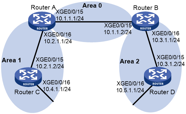
Procedure
1. Configure IP addresses for interfaces. (Details not shown.)
2. Enable OSPF:
# Configure Router A.
<RouterA> system-view
[RouterA] router id 10.2.1.1
[RouterA] ospf
[RouterA-ospf-1] area 0
[RouterA-ospf-1-area-0.0.0.0] network 10.1.1.0 0.0.0.255
[RouterA-ospf-1-area-0.0.0.0] quit
[RouterA-ospf-1] area 1
[RouterA-ospf-1-area-0.0.0.1] network 10.2.1.0 0.0.0.255
[RouterA-ospf-1-area-0.0.0.1] quit
[RouterA-ospf-1] quit
# Configure Router B.
<RouterB> system-view
[RouterB] router id 10.3.1.1
[RouterB] ospf
[RouterB-ospf-1] area 0
[RouterB-ospf-1-area-0.0.0.0] network 10.1.1.0 0.0.0.255
[RouterB-ospf-1-area-0.0.0.0] quit
[RouterB-ospf-1] area 2
[RouterB-ospf-1-area-0.0.0.2] network 10.3.1.0 0.0.0.255
[RouterB-ospf-1-area-0.0.0.2] quit
[RouterB-ospf-1] quit
# Configure Router C.
<RouterC> system-view
[RouterC] router id 10.4.1.1
[RouterC] ospf
[RouterC-ospf-1] area 1
[RouterC-ospf-1-area-0.0.0.1] network 10.2.1.0 0.0.0.255
[RouterC-ospf-1-area-0.0.0.1] network 10.4.1.0 0.0.0.255
[RouterC-ospf-1-area-0.0.0.1] quit
[RouterC-ospf-1] quit
# Configure Router D.
<RouterD> system-view
[RouterD] router id 10.5.1.1
[RouterD] ospf
[RouterD-ospf-1] area 2
[RouterD-ospf-1-area-0.0.0.2] network 10.3.1.0 0.0.0.255
[RouterD-ospf-1-area-0.0.0.2] network 10.5.1.0 0.0.0.255
[RouterD-ospf-1-area-0.0.0.2] quit
[RouterD-ospf-1] quit
Verifying the configuration
# Display the OSPF neighbors of Router A.
[RouterA] display ospf peer verbose
(M) Indicates MADJ neighbor
OSPF Process 1 with Router ID 10.2.1.1
Neighbors
Area 0.0.0.0 interface 10.1.1.1(Ten-GigabitEthernet0/0/15)'s neighbors
Router ID: 10.3.1.1 Address: 10.1.1.2 GR State: Normal
State: Full Mode: Nbr is master Priority: 1
DR: 10.1.1.1 BDR: 10.1.1.2 MTU: 0
Options is 0x02 (-|-|-|-|-|-|E|-)
Dead timer due in 37 sec
Neighbor is up for 06:03:59
Authentication Sequence: [ 0 ]
Neighbor state change count: 5
BFD status: Disabled
Area 0.0.0.1 interface 10.2.1.1(Ten-GigabitEthernet0/0/16)'s neighbors
Router ID: 10.4.1.1 Address: 10.2.1.2 GR State: Normal
State: Full Mode: Nbr is master Priority: 1
DR: 10.2.1.1 BDR: 10.2.1.2 MTU: 0
Options is 0x02 (-|-|-|-|-|-|E|-)
Dead timer due in 32 sec
Neighbor is up for 06:03:12
Authentication Sequence: [ 0 ]
Neighbor state change count: 5
BFD status: Disabled
# Display OSPF routing information on Router A.
[RouterA] display ospf routing
OSPF Process 1 with Router ID 10.2.1.1
Routing Table
Topology base (MTID 0)
Routing for network
Destination Cost Type NextHop AdvRouter Area
10.2.1.0/24 1 Transit 10.2.1.1 10.2.1.1 0.0.0.1
10.3.1.0/24 2 Inter 10.1.1.2 10.3.1.1 0.0.0.0
10.4.1.0/24 2 Stub 10.2.1.2 10.4.1.1 0.0.0.1
10.5.1.0/24 3 Inter 10.1.1.2 10.3.1.1 0.0.0.0
10.1.1.0/24 1 Transit 10.1.1.1 10.2.1.1 0.0.0.0
Total nets: 5
Intra area: 3 Inter area: 2 ASE: 0 NSSA: 0
# Display OSPF routing information on Router D.
[RouterD] display ospf routing
OSPF Process 1 with Router ID 10.5.1.1
Routing Table
Topology base (MTID 0)
Routing for network
Destination Cost Type NextHop AdvRouter Area
10.2.1.0/24 3 Inter 10.3.1.1 10.3.1.1 0.0.0.2
10.3.1.0/24 1 Transit 10.3.1.2 10.3.1.1 0.0.0.2
10.4.1.0/24 4 Inter 10.3.1.1 10.3.1.1 0.0.0.2
10.5.1.0/24 1 Stub 10.5.1.1 10.5.1.1 0.0.0.2
10.1.1.0/24 2 Inter 10.3.1.1 10.3.1.1 0.0.0.2
Total nets: 5
Intra area: 2 Inter area: 3 ASE: 0 NSSA: 0
# Ping 10.4.1.1 to test reachability.
[RouterD] ping 10.4.1.1
Ping 10.4.1.1 (10.4.1.1): 56 data bytes, press CTRL+C to break
56 bytes from 10.4.1.1: icmp_seq=0 ttl=253 time=1.549 ms
56 bytes from 10.4.1.1: icmp_seq=1 ttl=253 time=1.539 ms
56 bytes from 10.4.1.1: icmp_seq=2 ttl=253 time=0.779 ms
56 bytes from 10.4.1.1: icmp_seq=3 ttl=253 time=1.702 ms
56 bytes from 10.4.1.1: icmp_seq=4 ttl=253 time=1.471 ms
--- Ping statistics for 10.4.1.1 ---
5 packet(s) transmitted, 5 packet(s) received, 0.0% packet loss
round-trip min/avg/max/std-dev = 0.779/1.408/1.702/0.323 ms
Example: Configuring OSPF route redistribution
Network configuration
As shown in Figure 47:
· Enable OSPF on all the routers.
· Split the AS into three areas.
· Configure Router A and Router B as ABRs.
· Configure Router C as an ASBR to redistribute external routes (static routes).
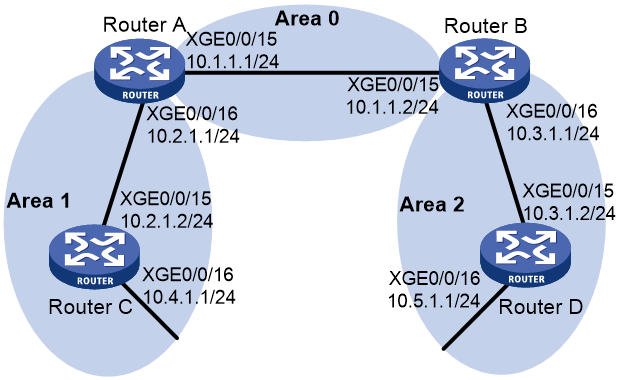
Procedure
1. Configure IP addresses for interfaces. (Details not shown.)
2. Enable OSPF (see "Example: Configuring basic OSPF").
3. Configure OSPF to redistribute routes:
# On Router C, configure a static route destined for network 3.1.2.0/24.
<RouterC> system-view
[RouterC] ip route-static 3.1.2.1 24 10.4.1.2
# On Router C, configure OSPF to redistribute the static route.
[RouterC] ospf 1
[RouterC-ospf-1] import-route static
Verifying the configuration
# Display the ABR/ASBR information on Router D.
<RouterD> display ospf abr-asbr
OSPF Process 1 with Router ID 10.5.1.1
Routing Table to ABR and ASBR
Topology base (MTID 0)
Type Destination Area Cost Nexthop RtType
Intra 10.3.1.1 0.0.0.2 10 10.3.1.1 ABR
Inter 10.4.1.1 0.0.0.2 22 10.3.1.1 ASBR
# Display the OSPF routing information on Router D.
<RouterD> display ospf routing
OSPF Process 1 with Router ID 10.5.1.1
Routing Table
Topology base (MTID 0)
Routing for network
Destination Cost Type NextHop AdvRouter Area
10.2.1.0/24 22 Inter 10.3.1.1 10.3.1.1 0.0.0.2
10.3.1.0/24 10 Transit 10.3.1.2 10.3.1.1 0.0.0.2
10.4.1.0/24 25 Inter 10.3.1.1 10.3.1.1 0.0.0.2
10.5.1.0/24 10 Stub 10.5.1.1 10.5.1.1 0.0.0.2
10.1.1.0/24 12 Inter 10.3.1.1 10.3.1.1 0.0.0.2
Routing for ASEs
Destination Cost Type Tag NextHop AdvRouter
3.1.2.0/24 1 Type2 1 10.3.1.1 10.4.1.1
Total nets: 6
Intra area: 2 Inter area: 3 ASE: 1 NSSA: 0
Example: Configuring OSPF route summarization
Network configuration
As shown in Figure 48:
· Configure OSPF on Router A and Router B in AS 200.
· Configure OSPF on Router C, Router D, and Router E in AS 100.
· Configure an EBGP connection between Router B and Router C. Configure Router B and Router C to redistribute OSPF routes and direct routes into BGP and BGP routes into OSPF.
· Configure Router B to advertise only summary route 10.0.0.0/8 to Router A.
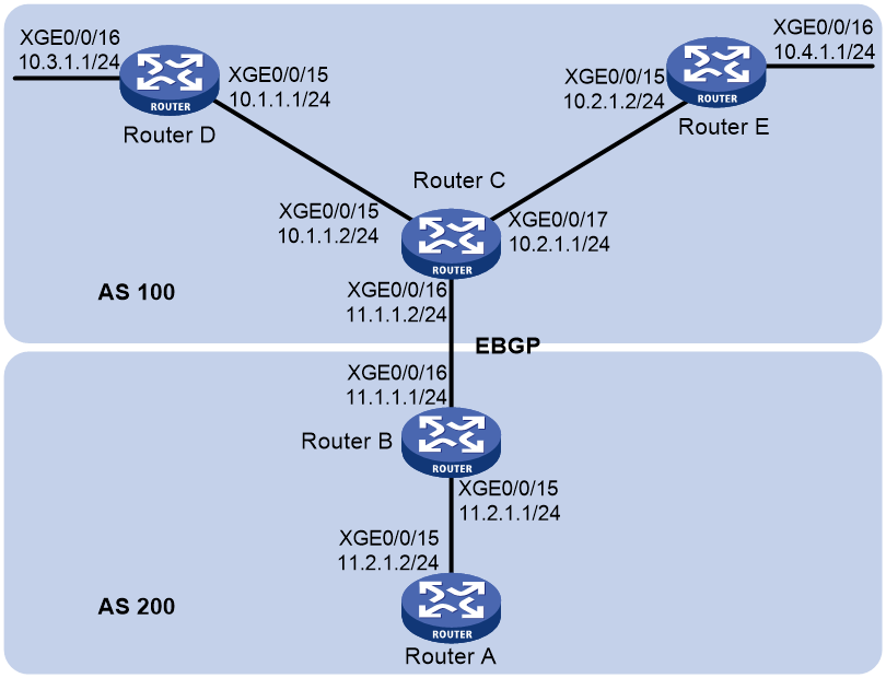
Procedure
1. Configure IP addresses for interfaces. (Details not shown.)
2. Enable OSPF:
# Configure Router A.
<RouterA> system-view
[RouterA] router id 11.2.1.2
[RouterA] ospf
[RouterA-ospf-1] area 0
[RouterA-ospf-1-area-0.0.0.0] network 11.2.1.0 0.0.0.255
[RouterA-ospf-1-area-0.0.0.0] quit
[RouterA-ospf-1] quit
# Configure Router B.
<RouterB> system-view
[RouterB] router id 11.2.1.1
[RouterB] ospf
[RouterB-ospf-1] area 0
[RouterB-ospf-1-area-0.0.0.0] network 11.2.1.0 0.0.0.255
[RouterB-ospf-1-area-0.0.0.0] quit
[RouterB-ospf-1] quit
# Configure Router C.
<RouterC> system-view
[RouterC] router id 11.1.1.2
[RouterC] ospf
[RouterC-ospf-1] area 0
[RouterC-ospf-1-area-0.0.0.0] network 10.1.1.0 0.0.0.255
[RouterC-ospf-1-area-0.0.0.0] network 10.2.1.0 0.0.0.255
[RouterC-ospf-1-area-0.0.0.0] quit
[RouterC-ospf-1] quit
# Configure Router D.
<RouterD> system-view
[RouterD] router id 10.3.1.1
[RouterD] ospf
[RouterD-ospf-1] area 0
[RouterD-ospf-1-area-0.0.0.0] network 10.1.1.0 0.0.0.255
[RouterD-ospf-1-area-0.0.0.0] network 10.3.1.0 0.0.0.255
[RouterD-ospf-1-area-0.0.0.0] quit
[RouterD-ospf-1] quit
# Configure Router E.
<RouterE> system-view
[RouterE] router id 10.4.1.1
[RouterE] ospf
[RouterE-ospf-1] area 0
[RouterE-ospf-1-area-0.0.0.0] network 10.2.1.0 0.0.0.255
[RouterE-ospf-1-area-0.0.0.0] network 10.4.1.0 0.0.0.255
[RouterE-ospf-1-area-0.0.0.0] quit
[RouterE-ospf-1] quit
3. Configure BGP to redistribute OSPF routes and direct routes:
# Configure Router B.
[RouterB] bgp 200
[RouterB-bgp-default] peer 11.1.1.2 as-number 100
[RouterB-bgp-default] address-family ipv4 unicast
[RouterB-bgp-default-ipv4] peer 11.1.1.2 enable
[RouterB-bgp-default-ipv4] import-route ospf
[RouterB-bgp-default-ipv4] import-route direct
[RouterB-bgp-default-ipv4] quit
[RouterB-bgp-default] quit
# Configure Router C.
[RouterC] bgp 100
[RouterC-bgp-default] peer 11.1.1.1 as-number 200
[RouterC-bgp-default] address-family ipv4 unicast
[RouterC-bgp-default-ipv4] peer 11.1.1.1 enable
[RouterC-bgp-default-ipv4] import-route ospf
[RouterC-bgp-default-ipv4] import-route direct
[RouterB-bgp-default-ipv4] quit
[RouterC-bgp-default] quit
4. Configure Router B and Router C to redistribute BGP routes into OSPF:
# Configure OSPF to redistribute routes from BGP on Router B.
[RouterB] ospf
[RouterB-ospf-1] import-route bgp
# Configure OSPF to redistribute routes from BGP on Router C.
[RouterC] ospf
[RouterC-ospf-1] import-route bgp
# Display the IP routing table on Router A.
[RouterA] display ip routing-table
Destinations : 14 Routes : 14
Destination/Mask Proto Pre Cost NextHop Interface
0.0.0.0/32 Direct 0 0 127.0.0.1 InLoop0
10.1.1.0/24 O_ASE2 150 1 11.2.1.1 XGE0/0/15
10.2.1.0/24 O_ASE2 150 1 11.2.1.1 XGE0/0/15
10.3.1.0/24 O_ASE2 150 1 11.2.1.1 XGE0/0/15
10.4.1.0/24 O_ASE2 150 1 11.2.1.1 XGE0/0/15
11.2.1.0/24 Direct 0 0 11.2.1.2 XGE0/0/15
11.2.1.0/32 Direct 0 0 11.2.1.2 XGE0/0/15
11.2.1.2/32 Direct 0 0 127.0.0.1 InLoop0
11.2.1.255/32 Direct 0 0 11.2.1.2 XGE0/0/15
127.0.0.0/8 Direct 0 0 127.0.0.1 InLoop0
127.0.0.0/32 Direct 0 0 127.0.0.1 InLoop0
127.0.0.1/32 Direct 0 0 127.0.0.1 InLoop0
127.255.255.255/32 Direct 0 0 127.0.0.1 InLoop0
255.255.255.255/32 Direct 0 0 127.0.0.1 InLoop0
5. Configure route summarization:
# Configure route summarization on Router B to advertise a single route 10.0.0.0/8.
[RouterB-ospf-1] asbr-summary 10.0.0.0 8
# Display the IP routing table on Router A.
[RouterA] display ip routing-table
Destinations : 11 Routes : 11
Destination/Mask Proto Pre Cost NextHop Interface
0.0.0.0/32 Direct 0 0 127.0.0.1 InLoop0
10.0.0.0/8 O_ASE2 150 1 11.2.1.1 XGE0/0/15
11.2.1.0/24 Direct 0 0 11.2.1.2 XGE0/0/15
11.2.1.0/32 Direct 0 0 11.2.1.2 XGE0/0/15
11.2.1.2/32 Direct 0 0 127.0.0.1 InLoop0
11.2.1.255/32 Direct 0 0 11.2.1.2 XGE0/0/15
127.0.0.0/8 Direct 0 0 127.0.0.1 InLoop0
127.0.0.0/32 Direct 0 0 127.0.0.1 InLoop0
127.0.0.1/32 Direct 0 0 127.0.0.1 InLoop0
127.255.255.255/32 Direct 0 0 127.0.0.1 InLoop0
255.255.255.255/32 Direct 0 0 127.0.0.1 InLoop0
The output shows that routes 10.1.1.0/24, 10.2.1.0/24, 10.3.1.0/24 and 10.4.1.0/24 are summarized into a single route 10.0.0.0/8.
Example: Configuring OSPF stub area
Network configuration
As shown in Figure 49:
· Enable OSPF on all routers, and split the AS into three areas.
· Configure Router A and Router B as ABRs to forward routing information between areas.
· Configure Router D as the ASBR to redistribute static routes.
· Configure Area 1 as a stub area to reduce advertised LSAs without influencing reachability.

Procedure
1. Configure IP addresses for interfaces. (Details not shown.)
2. Enable OSPF (see "Example: Configuring basic OSPF").
3. Configure route redistribution:
# Configure Router D to redistribute static routes.
<RouterD> system-view
[RouterD] ip route-static 3.1.2.1 24 10.5.1.2
[RouterD] ospf
[RouterD-ospf-1] import-route static
[RouterD-ospf-1] quit
# Display ABR/ASBR information on Router C.
<RouterC> display ospf abr-asbr
OSPF Process 1 with Router ID 10.4.1.1
Routing Table to ABR and ASBR
Topology base (MTID 0)
Type Destination Area Cost Nexthop RtType
Intra 10.2.1.1 0.0.0.1 3 10.2.1.1 ABR
Inter 10.5.1.1 0.0.0.1 7 10.2.1.1 ASBR
# Display OSPF routing information on Router C.
<RouterC> display ospf routing
OSPF Process 1 with Router ID 10.4.1.1
Routing Table
Topology base (MTID 0)
Routing for network
Destination Cost Type NextHop AdvRouter Area
10.2.1.0/24 3 Transit 0.0.0.0 10.2.1.1 0.0.0.1
10.3.1.0/24 7 Inter 10.2.1.1 10.2.1.1 0.0.0.1
10.4.1.0/24 3 Stub 10.4.1.1 10.4.1.1 0.0.0.1
10.5.1.0/24 17 Inter 10.2.1.1 10.2.1.1 0.0.0.1
10.1.1.0/24 5 Inter 10.2.1.1 10.2.1.1 0.0.0.1
Routing for ASEs
Destination Cost Type Tag NextHop AdvRouter
3.1.2.0/24 1 Type2 1 10.2.1.1 10.5.1.1
Total nets: 6
Intra area: 2 Inter area: 3 ASE: 1 NSSA: 0
The output shows that Router C's routing table contains an AS external route.
4. Configure Area 1 as a stub area:
# Configure Router A.
<RouterA> system-view
[RouterA] ospf
[RouterA-ospf-1] area 1
[RouterA-ospf-1-area-0.0.0.1] stub
[RouterA-ospf-1-area-0.0.0.1] quit
[RouterA-ospf-1] quit
# Configure Router C.
<RouterC> system-view
[RouterC] ospf
[RouterC-ospf-1] area 1
[RouterC-ospf-1-area-0.0.0.1] stub
[RouterC-ospf-1-area-0.0.0.1] quit
[RouterC-ospf-1] quit
# Display OSPF routing information on Router C.
[RouterC] display ospf routing
OSPF Process 1 with Router ID 10.4.1.1
Routing Table
Topology base (MTID 0)
Routing for network
Destination Cost Type NextHop AdvRouter Area
0.0.0.0/0 4 Inter 10.2.1.1 10.2.1.1 0.0.0.1
10.2.1.0/24 3 Transit 0.0.0.0 10.2.1.1 0.0.0.1
10.3.1.0/24 7 Inter 10.2.1.1 10.2.1.1 0.0.0.1
10.4.1.0/24 3 Stub 10.4.1.1 10.4.1.1 0.0.0.1
10.5.1.0/24 17 Inter 10.2.1.1 10.2.1.1 0.0.0.1
10.1.1.0/24 5 Inter 10.2.1.1 10.2.1.1 0.0.0.1
Total nets: 6
Intra area: 2 Inter area: 4 ASE: 0 NSSA: 0
The output shows that a default route replaces the AS external route.
# Configure Area 1 as a totally stub area.
[RouterA] ospf
[RouterA-ospf-1] area 1
[RouterA-ospf-1-area-0.0.0.1] stub no-summary
[RouterA-ospf-1-area-0.0.0.1] quit
# Display OSPF routing information on Router C.
[RouterC] display ospf routing
OSPF Process 1 with Router ID 10.4.1.1
Routing Table
Topology base (MTID 0)
Routing for network
Destination Cost Type NextHop AdvRouter Area
0.0.0.0/0 4 Inter 10.2.1.1 10.2.1.1 0.0.0.1
10.2.1.0/24 3 Transit 0.0.0.0 10.4.1.1 0.0.0.1
10.4.1.0/24 3 Stub 10.4.1.1 10.4.1.1 0.0.0.1
Total nets: 3
Intra area: 2 Inter area: 1 ASE: 0 NSSA: 0
The output shows that inter-area routes are removed, and only one external route (a default route) exists on Router C.
Example: Configuring OSPF NSSA area
Network configuration
As shown in Figure 50:
· Configure OSPF on all routers and split AS into three areas.
· Configure Router A and Router B as ABRs to forward routing information between areas.
· Configure Area 1 as an NSSA area and configure Router C as an ASBR to redistribute static routes into the AS.
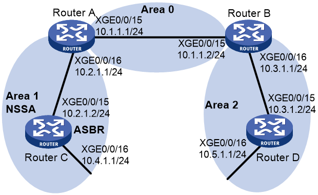
Procedure
1. Configure IP addresses for interfaces. (Details not shown.)
2. Enable OSPF (see "Example: Configuring basic OSPF").
3. Configure Area 1 as an NSSA area:
# Configure Router A.
<RouterA> system-view
[RouterA] ospf
[RouterA-ospf-1] area 1
[RouterA-ospf-1-area-0.0.0.1] nssa
[RouterA-ospf-1-area-0.0.0.1] quit
[RouterA-ospf-1] quit
# Configure Router C.
<RouterC> system-view
[RouterC] ospf
[RouterC-ospf-1] area 1
[RouterC-ospf-1-area-0.0.0.1] nssa
[RouterC-ospf-1-area-0.0.0.1] quit
[RouterC-ospf-1] quit
# Display routing information on Router C.
[RouterC] display ospf routing
OSPF Process 1 with Router ID 10.4.1.1
Routing Table
Topology base (MTID 0)
Routing for network
Destination Cost Type NextHop AdvRouter Area
10.2.1.0/24 3 Transit 10.2.1.2 10.4.1.1 0.0.0.1
10.3.1.0/24 7 Inter 10.2.1.1 10.2.1.1 0.0.0.1
10.4.1.0/24 3 Stub 10.4.1.1 10.4.1.1 0.0.0.1
10.5.1.0/24 17 Inter 10.2.1.1 10.2.1.1 0.0.0.1
10.1.1.0/24 5 Inter 10.2.1.1 10.2.1.1 0.0.0.1
Total nets: 5
Intra area: 2 Inter area: 3 ASE: 0 NSSA: 0
4. Configure route redistribution:
# Configure OSPF to redistribute the static route on Router C.
[RouterC] ip route-static 3.1.2.1 24 10.4.1.2
[RouterC] ospf
[RouterC-ospf-1] import-route static
[RouterC-ospf-1] quit
# Display routing information on Router D.
<RouterD> display ospf routing
OSPF Process 1 with Router ID 10.5.1.1
Routing Table
Topology base (MTID 0)
Routing for network
Destination Cost Type NextHop AdvRouter Area
10.2.1.0/24 22 Inter 10.3.1.1 10.3.1.1 0.0.0.2
10.3.1.0/24 10 Transit 10.3.1.2 10.3.1.1 0.0.0.2
10.4.1.0/24 25 Inter 10.3.1.1 10.3.1.1 0.0.0.2
10.5.1.0/24 10 Stub 10.5.1.1 10.5.1.1 0.0.0.2
10.1.1.0/24 12 Inter 10.3.1.1 10.3.1.1 0.0.0.2
Routing for ASEs
Destination Cost Type Tag NextHop AdvRouter
3.1.2.0/24 1 Type2 1 10.3.1.1 10.2.1.1
Total nets: 6
Intra area: 2 Inter area: 3 ASE: 1 NSSA: 0
The output shows that an AS external route imported from the NSSA area exists on Router D.
Example: Configuring OSPF DR election
Network configuration
As shown in Figure 51:
· Enable OSPF on Routers A, B, C, and D on the same network.
· Configure Router D as the DR, and configure Router C as the BDR.
· Change the router priorities on the interfaces to configure Router A as the DR and Router C as the BDR.
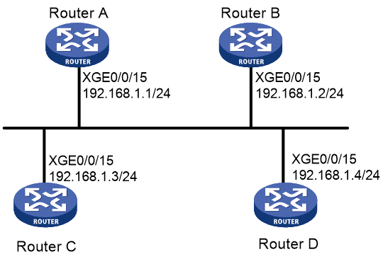
Procedure
1. Configure IP addresses for interfaces. (Details not shown.)
2. Configure basic OSPF settings on all routers. (Details not shown.)
For more information, see "Example: Configuring basic OSPF."
3. Display neighbor information on Router A.
[RouterA] display ospf peer verbose
(M) Indicates MADJ neighbor
OSPF Process 1 with Router ID 1.1.1.1
Neighbors
Area 0.0.0.0 interface 192.168.1.1(Ten-GigabitEthernet0/0/15)'s neighbors
Router ID: 2.2.2.2 Address: 192.168.1.2 GR State: Normal
State: 2-Way Mode: None Priority: 1
DR: 192.168.1.4 BDR: 192.168.1.3 MTU: 0
Options is 0x02 (-|-|-|-|-|-|E|-)
Dead timer due in 38 sec
Neighbor is up for 00:01:31
Authentication Sequence: [ 0 ]
Neighbor state change count: 6
BFD status: Disabled
Router ID: 3.3.3.3 Address: 192.168.1.3 GR State: Normal
State: Full Mode: Nbr is master Priority: 1
DR: 192.168.1.4 BDR: 192.168.1.3 MTU: 0
Options is 0x02 (-|-|-|-|-|-|E|-)
Dead timer due in 31 sec
Neighbor is up for 00:01:28
Authentication Sequence: [ 0 ]
Neighbor state change count: 6
BFD status: Disabled
Router ID: 4.4.4.4 Address: 192.168.1.4 GR State: Normal
State: Full Mode: Nbr is master Priority: 1
DR: 192.168.1.4 BDR: 192.168.1.3 MTU: 0
Options is 0x02 (-|-|-|-|-|-|E|-)
Dead timer due in 31 sec
Neighbor is up for 00:01:28
Authentication Sequence: [ 0 ]
Neighbor state change count: 6
BFD status: Disabled
The output shows that Router D is the DR and Router C is the BDR.
4. Configure router priorities on interfaces:
# Configure Router A.
[RouterA] interface ten-gigabitethernet 0/0/15
[RouterA-Ten-GigabitEthernet0/0/15] ospf dr-priority 100
[RouterA-Ten-GigabitEthernet0/0/15] quit
[RouterA] quit
# Configure Router B.
[RouterB] interface ten-gigabitethernet 0/0/15
[RouterB-Ten-GigabitEthernet0/0/15] ospf dr-priority 0
[RouterB-Ten-GigabitEthernet0/0/15] quit
[RouterB] quit
# Configure Router C.
[RouterC] interface ten-gigabitethernet 0/0/15
[RouterC-Ten-GigabitEthernet0/0/15] ospf dr-priority 2
[RouterC-Ten-GigabitEthernet0/0/15] quit
[RouterC] quit
# Display information about neighbors of Router D.
<RouterD> display ospf peer verbose
(M) Indicates MADJ neighbor
OSPF Process 1 with Router ID 4.4.4.4
Neighbors
Area 0.0.0.0 interface 192.168.1.4(Ten-GigabitEthernet0/0/15)'s neighbors
Router ID: 1.1.1.1 Address: 192.168.1.1 GR State: Normal
State: Full Mode:Nbr is slave Priority: 100
DR: 192.168.1.4 BDR: 192.168.1.3 MTU: 0
Options is 0x02 (-|-|-|-|-|-|E|-)
Dead timer due in 31 sec
Neighbor is up for 00:11:17
Authentication Sequence: [ 0 ]
Neighbor state change count: 6
BFD status: Disabled
Router ID: 2.2.2.2 Address: 192.168.1.2 GR State: Normal
State: Full Mode:Nbr is slave Priority: 0
DR: 192.168.1.4 BDR: 192.168.1.3 MTU: 0
Options is 0x02 (-|-|-|-|-|-|E|-)
Dead timer due in 35 sec
Neighbor is up for 00:11:19
Authentication Sequence: [ 0 ]
Neighbor state change count: 6
BFD status: Disabled
Router ID: 3.3.3.3 Address: 192.168.1.3 GR State: Normal
State: Full Mode:Nbr is slave Priority: 2
DR: 192.168.1.4 BDR: 192.168.1.3 MTU: 0
Options is 0x02 (-|-|-|-|-|-|E|-)
Dead timer due in 33 sec
Neighbor is up for 00:11:15
Authentication Sequence: [ 0 ]
Neighbor state change count: 6
BFD status: Disabled
The output shows that the DR and BDR are not changed, because the new router priority settings do not take effect immediately.
5. Restart OSPF processes:
# Restart the OSPF process on Router A.
<RouterA> reset ospf 1 process
Warning : Reset OSPF process? [Y/N]:y
# Restart the OSPF process on Router B.
<RouterB> reset ospf 1 process
Warning : Reset OSPF process? [Y/N]:y
# Restart the OSPF process on Router C.
<RouterC> reset ospf 1 process
Warning : Reset OSPF process? [Y/N]:y
# Restart the OSPF process on Router D.
<RouterD> reset ospf 1 process
Warning : Reset OSPF process? [Y/N]:y
# Display neighbor information on Router D.
<RouterD> display ospf peer verbose
(M) Indicates MADJ neighbor
OSPF Process 1 with Router ID 4.4.4.4
Neighbors
Area 0.0.0.0 interface 192.168.1.4(Ten-GigabitEthernet0/0/15)'s neighbors
Router ID: 1.1.1.1 Address: 192.168.1.1 GR State: Normal
State: Full Mode: Nbr is slave Priority: 100
DR: 192.168.1.1 BDR: 192.168.1.3 MTU: 0
Options is 0x02 (-|-|-|-|-|-|E|-)
Dead timer due in 39 sec
Neighbor is up for 00:01:40
Authentication Sequence: [ 0 ]
Neighbor state change count: 6
BFD status: Disabled
Router ID: 2.2.2.2 Address: 192.168.1.2 GR State: Normal
State: 2-Way Mode: None Priority: 0
DR: 192.168.1.1 BDR: 192.168.1.3 MTU: 0
Options is 0x02 (-|-|-|-|-|-|E|-)
Dead timer due in 35 sec
Neighbor is up for 00:01:44
Authentication Sequence: [ 0 ]
Neighbor state change count: 6
BFD status: Disabled
Router ID: 3.3.3.3 Address: 192.168.1.3 GR State: Normal
State: Full Mode: Nbr is slave Priority: 2
DR: 192.168.1.1 BDR: 192.168.1.3 MTU: 0
Options is 0x02 (-|-|-|-|-|-|E|-)
Dead timer due in 39 sec
Neighbor is up for 00:01:41
Authentication Sequence: [ 0 ]
Neighbor state change count: 6
BFD status: Disabled
The output shows that Router A becomes the DR and Router C becomes the BDR.
The full neighbor state means an adjacency has been established. The 2-way neighbor state means the two routers are not the DR or BDR, and they do not exchange LSAs.
# Display OSPF interface information.
<RouterA> display ospf interface
(M) Indicates MADJ interface
OSPF Process 1 with Router ID 1.1.1.1
Interfaces
Area: 0.0.0.0
IP Address Type State Cost Pri DR BDR
192.168.1.1 Broadcast DR 1 100 192.168.1.1 192.168.1.3
<RouterB> display ospf interface
(M) Indicates MADJ interface
OSPF Process 1 with Router ID 2.2.2.2
Interfaces
Area: 0.0.0.0
IP Address Type State Cost Pri DR BDR
192.168.1.2 Broadcast DROther 1 0 192.168.1.1 192.168.1.3
The interface state DROther means the interface is not the DR or BDR.
Example: Configuring OSPF virtual link
Network configuration
As shown in Figure 52, configure a virtual link between Router B and Router C to connect Area 2 to the backbone area. After configuration, Router B can learn routes to Area 2.
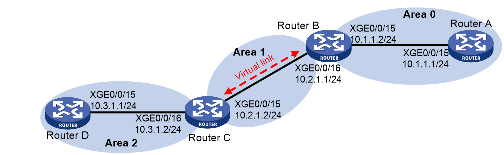
Procedure
1. Configure IP addresses for interfaces. (Details not shown.)
2. Enable OSPF:
# Configure Router A.
<RouterA> system-view
[RouterA] ospf 1 router-id 1.1.1.1
[RouterA-ospf-1] area 0
[RouterA-ospf-1-area-0.0.0.0] network 10.1.1.0 0.0.0.255
[RouterA-ospf-1-area-0.0.0.0] quit
[RouterA-ospf-1] quit
# Configure Router B.
<RouterB> system-view
[RouterB] ospf 1 router-id 2.2.2.2
[RouterB-ospf-1] area 0
[RouterB-ospf-1-area-0.0.0.0] network 10.1.1.0 0.0.0.255
[RouterB-ospf-1-area-0.0.0.0] quit
[RouterB-ospf-1] area 1
[RouterB–ospf-1-area-0.0.0.1] network 10.2.1.0 0.0.0.255
[RouterB–ospf-1-area-0.0.0.1] quit
[RouterB-ospf-1] quit
# Configure Router C.
<RouterC> system-view
[RouterC] ospf 1 router-id 3.3.3.3
[RouterC-ospf-1] area 1
[RouterC-ospf-1-area-0.0.0.1] network 10.2.1.0 0.0.0.255
[RouterC-ospf-1-area-0.0.0.1] quit
[RouterC-ospf-1] area 2
[RouterC–ospf-1-area-0.0.0.2] network 10.3.1.0 0.0.0.255
[RouterC–ospf-1-area-0.0.0.2] quit
[RouterC-ospf-1] quit
# Configure Router D.
<RouterD> system-view
[RouterD] ospf 1 router-id 4.4.4.4
[RouterD-ospf-1] area 2
[RouterD-ospf-1-area-0.0.0.2] network 10.3.1.0 0.0.0.255
[RouterD-ospf-1-area-0.0.0.2] quit
[RouterD-ospf-1] quit
# Display OSPF routing information on Router B.
[RouterB] display ospf routing
OSPF Process 1 with Router ID 2.2.2.2
Routing Table
Topology base (MTID 0)
Routing for network
Destination Cost Type NextHop AdvRouter Area
10.2.1.0/24 2 Transit 10.2.1.1 3.3.3.3 0.0.0.1
10.1.1.0/24 2 Transit 10.1.1.2 2.2.2.2 0.0.0.0
Total nets: 2
Intra area: 2 Inter area: 0 ASE: 0 NSSA: 0
The output shows that Router B does not have routes to Area 2 because Area 0 is not directly connected to Area 2.
3. Configure a virtual link:
# Configure Router B.
[RouterB] ospf
[RouterB-ospf-1] area 1
[RouterB-ospf-1-area-0.0.0.1] vlink-peer 3.3.3.3
[RouterB-ospf-1-area-0.0.0.1] quit
[RouterB-ospf-1] quit
# Configure Router C.
[RouterC] ospf
[RouterC-ospf-1] area 1
[RouterC-ospf-1-area-0.0.0.1] vlink-peer 2.2.2.2
[RouterC-ospf-1-area-0.0.0.1] quit
[RouterC-ospf-1] quit
# Display OSPF routing information on Router B.
[RouterB] display ospf routing
OSPF Process 1 with Router ID 2.2.2.2
Routing Table
Topology base (MTID 0)
Routing for network
Destination Cost Type NextHop AdvRouter Area
10.2.1.0/24 2 Transit 10.2.1.1 3.3.3.3 0.0.0.1
10.3.1.0/24 5 Inter 10.2.1.2 3.3.3.3 0.0.0.0
10.1.1.0/24 2 Transit 10.1.1.2 2.2.2.2 0.0.0.0
Total nets: 3
Intra area: 2 Inter area: 1 ASE: 0 NSSA: 0
The output shows that Router B has learned the route 10.3.1.0/24 to Area 2.
Example: Configuring OSPF GR
Network configuration
As shown in Figure 53:
· Router A, Router B, and Router C that belong to the same autonomous system and the same OSPF routing domain are GR capable.
· Router A acts as the non-IETF GR restarter. Router B and Router C are the GR helpers, and synchronize their LSDBs with Router A through OOB communication of GR.
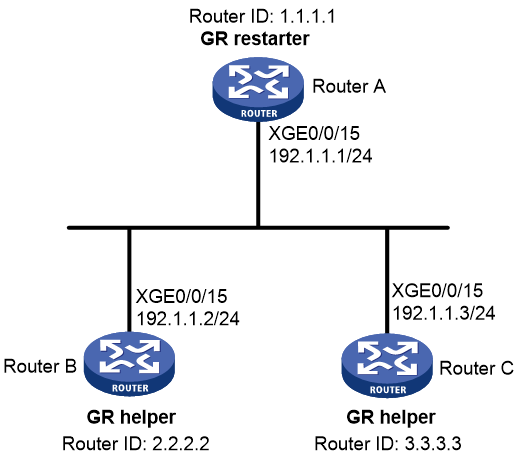
Procedure
1. Configure IP addresses for interfaces. (Details not shown.)
2. Enable OSPF:
# Configure Router A.
<RouterA> system-view
[RouterA] router id 1.1.1.1
[RouterA] ospf 100
[RouterA-ospf-100] area 0
[RouterA-ospf-100-area-0.0.0.0] network 192.1.1.0 0.0.0.255
[RouterA-ospf-100-area-0.0.0.0] quit
# Configure Router B.
<RouterB> system-view
[RouterB] router id 2.2.2.2
[RouterB] ospf 100
[RouterB-ospf-100] area 0
[RouterB-ospf-100-area-0.0.0.0] network 192.1.1.0 0.0.0.255
[RouterB-ospf-100-area-0.0.0.0] quit
# Configure Router C.
<RouterC> system-view
[RouterC] router id 3.3.3.3
[RouterC] ospf 100
[RouterC-ospf-100] area 0
[RouterC-ospf-100-area-0.0.0.0] network 192.1.1.0 0.0.0.255
[RouterC-ospf-100-area-0.0.0.0] quit
3. Configure OSPF GR:
# Configure Router A as the non-IETF OSPF GR restarter: enable the link-local signaling capability, the out-of-band re-synchronization capability, and non-IETF GR for OSPF process 100.
[RouterA-ospf-100] enable link-local-signaling
[RouterA-ospf-100] enable out-of-band-resynchronization
[RouterA-ospf-100] graceful-restart
[RouterA-ospf-100] quit
[RouterA] quit
# Configure Router B as the GR helper: enable the link-local signaling capability and the out-of-band re-synchronization capability for OSPF process 100.
[RouterB-ospf-100] enable link-local-signaling
[RouterB-ospf-100] enable out-of-band-resynchronization
# Configure Router C as the GR helper: enable the link-local signaling capability and the out-of-band re-synchronization capability for OSPF process 100.
[RouterC-ospf-100] enable link-local-signaling
[RouterC-ospf-100] enable out-of-band-resynchronization
Verifying the configuration
# Enable OSPF GR event debugging and restart the OSPF process by using GR on Router A.
<RouterA> debugging ospf event graceful-restart
<RouterA> terminal monitor
<RouterA> terminal logging level 7
<RouterA> reset ospf 100 process graceful-restart
Reset OSPF process? [Y/N]:y
%Oct 21 15:29:28:727 2011 RouterA OSPF/5/OSPF_NBR_CHG: OSPF 100 Neighbor 192.1.1.2(Ten-GigabitEthernet0/0/15) from Full to Down.
%Oct 21 15:29:28:729 2011 RouterA OSPF/5/OSPF_NBR_CHG: OSPF 100 Neighbor 192.1.1.3(Ten-GigabitEthernet0/0/15) from Full to Down.
*Oct 21 15:29:28:735 2011 RouterA OSPF/7/DEBUG:
OSPF 100 nonstandard GR Started for OSPF Router
*Oct 21 15:29:28:735 2011 RouterA OSPF/7/DEBUG:
OSPF 100 created GR wait timer,timeout interval is 40(s).
*Oct 21 15:29:28:735 2011 RouterA OSPF/7/DEBUG:
OSPF 100 created GR Interval timer,timeout interval is 120(s).
*Oct 21 15:29:28:758 2011 RouterA OSPF/7/DEBUG:
OSPF 100 created OOB Progress timer for neighbor 192.1.1.3.
*Oct 21 15:29:28:766 2011 RouterA OSPF/7/DEBUG:
OSPF 100 created OOB Progress timer for neighbor 192.1.1.2.
%Oct 21 15:29:29:902 2011 RouterA OSPF/5/OSPF_NBR_CHG: OSPF 100 Neighbor 192.1.1.2(Ten-GigabitEthernet0/0/15) from Loading to Full.
*Oct 21 15:29:29:902 2011 RouterA OSPF/7/DEBUG:
OSPF 100 deleted OOB Progress timer for neighbor 192.1.1.2.
%Oct 21 15:29:30:897 2011 RouterA OSPF/5/OSPF_NBR_CHG: OSPF 100 Neighbor 192.1.1.3(Ten-GigabitEthernet0/0/15) from Loading to Full.
*Oct 21 15:29:30:897 2011 RouterA OSPF/7/DEBUG:
OSPF 100 deleted OOB Progress timer for neighbor 192.1.1.3.
*Oct 21 15:29:30:911 2011 RouterA OSPF/7/DEBUG:
OSPF GR: Process 100 Exit Restart,Reason : DR or BDR change,for neighbor : 192.1.1.3.
*Oct 21 15:29:30:911 2011 RouterA OSPF/7/DEBUG:
OSPF 100 deleted GR Interval timer.
*Oct 21 15:29:30:912 2011 RouterA OSPF/7/DEBUG:
OSPF 100 deleted GR wait timer.
%Oct 21 15:29:30:920 2011 RouterA OSPF/5/OSPF_NBR_CHG: OSPF 100 Neighbor 192.1.1.2(Ten-GigabitEthernet0/0/15) from Full to Down.
%Oct 21 15:29:30:921 2011 RouterA OSPF/5/OSPF_NBR_CHG: OSPF 100 Neighbor 192.1.1.3(Ten-GigabitEthernet0/0/15) from Full to Down.
%Oct 21 15:29:33:815 2011 RouterA OSPF/5/OSPF_NBR_CHG: OSPF 100 Neighbor 192.1.1.3(Ten-GigabitEthernet0/0/15) from Loading to Full.
%Oct 21 15:29:35:578 2011 RouterA OSPF/5/OSPF_NBR_CHG: OSPF 100 Neighbor 192.1.1.2(Ten-GigabitEthernet0/0/15) from Loading to Full.
The output shows that Router A completes GR.
Example: Configuring BFD for OSPF
Network configuration
As shown in Figure 54, run OSPF on Router A, Router B, and Router C so that they can reach each other at the network layer.
· When the link over which Router A and Router B communicate through a Layer 2 switch fails, BFD can quickly detect the failure and notify OSPF of the failure.
· Router A and Router B then communicate through Router C.
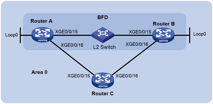
Table 22 Interface and IP address assignment
|
Device |
Interface |
IP address |
|
Router A |
XGE0/0/15 |
192.168.0.102/24 |
|
Router A |
XGE0/0/16 |
10.1.1.102/24 |
|
Router A |
Loop0 |
121.1.1.1/32 |
|
Router B |
XGE0/0/15 |
192.168.0.100/24 |
|
Router B |
XGE0/0/16 |
13.1.1.1/24 |
|
Router B |
Loop0 |
120.1.1.1/32 |
|
Router C |
XGE0/0/15 |
10.1.1.100/24 |
|
Router C |
XGE0/0/16 |
13.1.1.2/24 |
Procedure
1. Configure IP addresses for interfaces. (Details not shown.)
2. Enable OSPF:
# Configure Router A.
<RouterA> system-view
[RouterA] ospf
[RouterA-ospf-1] area 0
[RouterA-ospf-1-area-0.0.0.0] network 192.168.0.0 0.0.0.255
[RouterA-ospf-1-area-0.0.0.0] network 10.1.1.0 0.0.0.255
[RouterA-ospf-1-area-0.0.0.0] network 121.1.1.1 0.0.0.0
[RouterA-ospf-1-area-0.0.0.0] quit
[RouterA-ospf-1] quit
# Configure Router B.
<RouterB> system-view
[RouterB] ospf
[RouterB-ospf-1] area 0
[RouterB-ospf-1-area-0.0.0.0] network 192.168.0.0 0.0.0.255
[RouterB-ospf-1-area-0.0.0.0] network 13.1.1.0 0.0.0.255
[RouterB-ospf-1-area-0.0.0.0] network 120.1.1.1 0.0.0.0
[RouterB-ospf-1-area-0.0.0.0] quit
[RouterB-ospf-1] quit
# Configure Router C.
<RouterC> system-view
[RouterC] ospf
[RouterC-ospf-1] area 0
[RouterC-ospf-1-area-0.0.0.0] network 10.1.1.0 0.0.0.255
[RouterC-ospf-1-area-0.0.0.0] network 13.1.1.0 0.0.0.255
[RouterC-ospf-1-area-0.0.0.0] quit
[RouterC-ospf-1] quit
3. Configure BFD:
# Enable BFD on Router A and configure BFD parameters.
[RouterA] bfd session init-mode active
[RouterA] interface ten-gigabitethernet 0/0/15
[RouterA-Ten-GigabitEthernet0/0/15] ospf bfd enable
[RouterA-Ten-GigabitEthernet0/0/15] bfd min-transmit-interval 500
[RouterA-Ten-GigabitEthernet0/0/15] bfd min-receive-interval 500
[RouterA-Ten-GigabitEthernet0/0/15] bfd detect-multiplier 7
[RouterA-Ten-GigabitEthernet0/0/15] quit
[RouterA] quit
# Enable BFD on Router B and configure BFD parameters.
[RouterB] bfd session init-mode active
[RouterB] interface ten-gigabitethernet 0/0/15
[RouterB-Ten-GigabitEthernet0/0/15] ospf bfd enable
[RouterB-Ten-GigabitEthernet0/0/15] bfd min-transmit-interval 500
[RouterB-Ten-GigabitEthernet0/0/15] bfd min-receive-interval 500
[RouterB-Ten-GigabitEthernet0/0/15] bfd detect-multiplier 6
[RouterB-Ten-GigabitEthernet0/0/15] quit
Verifying the configuration
# Display the BFD information on Router A.
<RouterA> display bfd session
Total sessions: 1 Up sessions: 1 Init mode: Active
IPv4 session working in control packet mode:
LD/RD SourceAddr DestAddr State Holdtime Interface
3/1 192.168.0.102 192.168.0.100 Up 1700ms XGE0/0/15
# Display routes destined for 120.1.1.1/32 on Router A.
<RouterA> display ip routing-table 120.1.1.1 verbose
Summary Count : 1
Destination: 120.1.1.1/32
Protocol: O_INTRA
Process ID: 1
SubProtID: 0x1 Age: 04h20m37s
FlushedAge: 15h28m49s
Cost: 1 Preference: 10
IpPre: N/A QosLocalID: N/A
Tag: 0 State: Active Adv
OrigTblID: 0x0 OrigVrf: default-vrf
TableID: 0x2 OrigAs: 0
NibID: 0x26000002 LastAs: 0
AttrID: 0xffffffff
BkAttrID: 0xffffffff Neighbor: 0.0.0.0
Flags: 0x1008c OrigNextHop: 192.168.0.100
Label: NULL RealNextHop: 192.168.0.100
BkLabel: NULL BkNextHop: N/A
SRLabel: NULL Interface: Ten-GigabitEthernet0/0/15
BkSRLabel: NULL BkInterface: N/A
Tunnel ID: Invalid IPInterface: Ten-GigabitEthernet0/0/15
BkTunnel ID: Invalid BkIPInterface: N/A
InLabel: NULL ColorInterface: N/A
SIDIndex: NULL BkColorInterface: N/A
FtnIndex: 0x0 TunnelInterface: N/A
TrafficIndex: N/A BkTunnelInterface: N/A
Connector: N/A PathID: 0x0
UserID: 0x0 SRTunnelID: Invalid
SID Type: N/A NID: Invalid
FlushNID: Invalid BkNID: Invalid
BkFlushNID: Invalid StatFlags: 0x0
SID: N/A
BkSID: N/A
CommBlockLen: 0 Priority: Critical
MemberPort: N/A ExtFlags: 0x0
UCMIndex: 0x0 UserVLAN: 65535
UCMMTU: 0 BrasHash: 0
SessionID: 0 UserGroupID: 0
IsoGroupID: 0 BkIsoGroupID: 0
The output shows that Router A communicates with Router B through Ten-GigabitEthernet 0/0/15. Then the link over Ten-GigabitEthernet 0/0/15 fails.
# Display routes destined for 120.1.1.1/32 on Router A.
<RouterA> display ip routing-table 120.1.1.1 verbose
Summary Count : 1
Destination: 120.1.1.1/32
Protocol: O_INTRA
Process ID: 1
SubProtID: 0x1 Age: 04h20m37s
FlushedAge: 15h28m49s
Cost: 2 Preference: 10
IpPre: N/A QosLocalID: N/A
Tag: 0 State: Active Adv
OrigTblID: 0x0 OrigVrf: default-vrf
TableID: 0x2 OrigAs: 0
NibID: 0x26000002 LastAs: 0
AttrID: 0xffffffff
BkAttrID: 0xffffffff Neighbor: 0.0.0.0
Flags: 0x1008c OrigNextHop: 10.1.1.100
Label: NULL RealNextHop: 10.1.1.100
BkLabel: NULL BkNextHop: N/A
SRLabel: NULL Interface: Ten-GigabitEthernet0/0/16
BkSRLabel: NULL BkInterface: N/A
Tunnel ID: Invalid IPInterface: Ten-GigabitEthernet0/0/16
BkTunnel ID: Invalid BkIPInterface: N/A
InLabel: NULL ColorInterface: N/A
SIDIndex: NULL BkColorInterface: N/A
FtnIndex: 0x0 TunnelInterface: N/A
TrafficIndex: N/A BkTunnelInterface: N/A
Connector: N/A PathID: 0x0
UserID: 0x0 SRTunnelID: Invalid
SID Type: N/A NID: Invalid
FlushNID: Invalid BkNID: Invalid
BkFlushNID: Invalid StatFlags: 0x0
SID: N/A
BkSID: N/A
CommBlockLen: 0 Priority: Critical
MemberPort: N/A ExtFlags: 0x0
UCMIndex: 0x0 UserVLAN: 65535
UCMMTU: 0 BrasHash: 0
SessionID: 0 UserGroupID: 0
IsoGroupID: 0 BkIsoGroupID: 0
The output shows that Router A communicates with Router B through Ten-GigabitEthernet 0/0/16.
Example: Configuring OSPF FRR
Network configuration
As shown in Figure 55, Router A, Router B, and Router C reside in the same OSPF domain. Configure OSPF FRR so that when Link A fails, traffic is immediately switched to Link B.
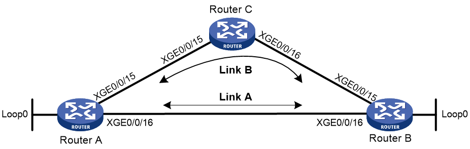
Table 23 Interface and IP address assignment
|
Device |
Interface |
IP address |
|
Router A |
XGE0/0/15 |
12.12.12.1/24 |
|
Router A |
XGE0/0/16 |
13.13.13.1/24 |
|
Router A |
Loop0 |
1.1.1.1/32 |
|
Router B |
XGE0/0/15 |
24.24.24.4/24 |
|
Router B |
XGE0/0/16 |
13.13.13.2/24 |
|
Router B |
Loop0 |
4.4.4.4/32 |
|
Router C |
XGE0/0/15 |
12.12.12.2/24 |
|
Router C |
XGE0/0/16 |
24.24.24.2/24 |
Procedure
1. Configure IP addresses and subnet masks for interfaces on the routers. (Details not shown.)
2. Configure OSPF on the routers to ensure that Router A, Router B, and Router C can communicate with each other at the network layer. (Details not shown.)
3. Configure OSPF FRR:
You can enable OSPF FRR to either calculate a backup next hop by using the LFA algorithm, or specify a backup next hop by using a routing policy.
¡ (Method 1.) Enable OSPF FRR to calculate a backup next hop by using the LFA algorithm:
# Configure Router A.
<RouterA> system-view
[RouterA] ospf 1
[RouterA-ospf-1] fast-reroute lfa
[RouterA-ospf-1] quit
# Configure Router B.
<RouterB> system-view
[RouterB] ospf 1
[RouterB-ospf-1] fast-reroute lfa
[RouterB-ospf-1] quit
¡ (Method 2.) Enable OSPF FRR to specify a backup next hop by using a routing policy:
# Configure Router A.
<RouterA> system-view
[RouterA] ip prefix-list abc index 10 permit 4.4.4.4 32
[RouterA] route-policy frr permit node 10
[RouterA-route-policy-frr-10] if-match ip address prefix-list abc
[RouterA-route-policy-frr-10] apply fast-reroute backup-interface ten-gigabitethernet 0/0/15 backup-nexthop 12.12.12.2
[RouterA-route-policy-frr-10] quit
[RouterA] ospf 1
[RouterA-ospf-1] fast-reroute route-policy frr
[RouterA-ospf-1] quit
# Configure Router B.
<RouterB> system-view
[RouterB] ip prefix-list abc index 10 permit 1.1.1.1 32
[RouterB] route-policy frr permit node 10
[RouterB-route-policy-frr-10] if-match ip address prefix-list abc
[RouterB-route-policy-frr-10] apply fast-reroute backup-interface ten-gigabitethernet 0/0/15 backup-nexthop 24.24.24.2
[RouterB-route-policy-frr-10] quit
[RouterB] ospf 1
[RouterB-ospf-1] fast-reroute route-policy frr
[RouterB-ospf-1] quit
Verifying the configuration
# Display route 4.4.4.4/32 on Router A to view the backup next hop information.
[RouterA] display ip routing-table 4.4.4.4 verbose
Summary Count : 1
Destination: 4.4.4.4/32
Protocol: O_INTRA
Process ID: 1
SubProtID: 0x1 Age: 04h20m37s
FlushedAge: 15h28m49s
Cost: 1 Preference: 10
IpPre: N/A QosLocalID: N/A
Tag: 0 State: Active Adv
OrigTblID: 0x0 OrigVrf: default-vrf
TableID: 0x2 OrigAs: 0
NibID: 0x26000002 LastAs: 0
AttrID: 0xffffffff
BkAttrID: 0xffffffff Neighbor: 0.0.0.0
Flags: 0x1008c OrigNextHop: 13.13.13.2
Label: NULL RealNextHop: 13.13.13.2
BkLabel: NULL BkNextHop: 12.12.12.2
SRLabel: NULL Interface: Ten-GigabitEthernet0/0/16
BkSRLabel: NULL BkInterface: N/A
Tunnel ID: Invalid IPInterface: Ten-GigabitEthernet0/0/16
BkTunnel ID: Invalid BkIPInterface: Ten-GigabitEthernet0/0/15
InLabel: NULL ColorInterface: N/A
SIDIndex: NULL BkColorInterface: N/A
FtnIndex: 0x0 TunnelInterface: N/A
TrafficIndex: N/A BkTunnelInterface: N/A
Connector: N/A PathID: 0x0
UserID: 0x0 SRTunnelID: Invalid
SID Type: N/A NID: Invalid
FlushNID: Invalid BkNID: Invalid
BkFlushNID: Invalid StatFlags: 0x0
SID: N/A
BkSID: N/A
CommBlockLen: 0 Priority: Critical
MemberPort: N/A ExtFlags: 0x0
UCMIndex: 0x0 UserVLAN: 65535
UCMMTU: 0 BrasHash: 0
SessionID: 0 UserGroupID: 0
# Display route 1.1.1.1/32 on Router B to view the backup next hop information.
[RouterB] display ip routing-table 1.1.1.1 verbose
Summary Count : 1
Destination: 1.1.1.1/32
Protocol: O_INTRA
Process ID: 1
SubProtID: 0x1 Age: 04h20m37s
FlushedAge: 15h28m49s
Cost: 1 Preference: 10
IpPre: N/A QosLocalID: N/A
Tag: 0 State: Active Adv
OrigTblID: 0x0 OrigVrf: default-vrf
TableID: 0x2 OrigAs: 0
NibID: 0x26000002 LastAs: 0
AttrID: 0xffffffff
BkAttrID: 0xffffffff Neighbor: 0.0.0.0
Flags: 0x1008c OrigNextHop: 13.13.13.1
Label: NULL RealNextHop: 13.13.13.1
BkLabel: NULL BkNextHop: 24.24.24.2
SRLabel: NULL Interface: Ten-GigabitEthernet0/0/16
BkSRLabel: NULL BkInterface: N/A
Tunnel ID: Invalid IPInterface: Ten-GigabitEthernet0/0/16
BkTunnel ID: Invalid BkIPInterface: Ten-GigabitEthernet0/0/15
InLabel: NULL ColorInterface: N/A
SIDIndex: NULL BkColorInterface: N/A
FtnIndex: 0x0 TunnelInterface: N/A
TrafficIndex: N/A BkTunnelInterface: N/A
Connector: N/A PathID: 0x0
UserID: 0x0 SRTunnelID: Invalid
SID Type: N/A NID: Invalid
FlushNID: Invalid BkNID: Invalid
BkFlushNID: Invalid StatFlags: 0x0
SID: N/A
BkSID: N/A
CommBlockLen: 0 Priority: Critical
MemberPort: N/A ExtFlags: 0x0
UCMIndex: 0x0 UserVLAN: 65535
UCMMTU: 0 BrasHash: 0
SessionID: 0 UserGroupID: 0
Example: Configuring an OSPF stub router
Network configuration
As shown in Figure 56, all devices run BGP. Router E and Router F are EBGP peers. Router A and Router B, Router A and Router D, Router B and Router C, and Router C and Router D are IBGP peers. Configure Router B as a stub router during BGP route convergence. Router A will forward traffic to Router D instead of Router B until Router B finishes BGP convergence, which avoids traffic disruption from Router A to AS 20.
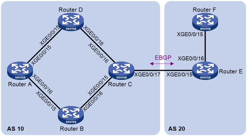
Table 24 Interface and IP address assignment
|
Device |
Interface |
IP address |
|
Router A |
XGE0/0/15 |
10.1.2.1/30 |
|
Router A |
XGE0/0/16 |
10.1.1.1/30 |
|
Router A |
Loop0 |
1.1.1.1/32 |
|
Router B |
XGE0/0/15 |
10.1.1.2/30 |
|
Router B |
XGE0/0/16 |
10.1.3.1/30 |
|
Router B |
Loop0 |
2.2.2.2/32 |
|
Router C |
XGE0/0/15 |
10.1.3.2/30 |
|
Router C |
XGE0/0/16 |
10.1.4.2/30 |
|
Router C |
XGE0/0/17 |
10.2.1.1/30 |
|
Router C |
Loop0 |
3.3.3.3/32 |
|
Router D |
XGE0/0/15 |
10.1.2.2/30 |
|
Router D |
XGE0/0/16 |
10.1.4.1/30 |
|
Router D |
Loop0 |
4.4.4.4/32 |
Procedure
1. Configure IP addresses for interfaces on the routers.
Configure IP addresses for interfaces on the routers. (Details not shown.)
2. Configure OSPF:
# Configure Router A.
<RouterA> system-view
[RouterA] ospf 1
[RouterA-ospf-1] area 0
[RouterA-ospf-1-area-0.0.0.0] network 10.1.1.0 0.0.0.3
[RouterA-ospf-1-area-0.0.0.0] network 10.1.2.0 0.0.0.3
[RouterA-ospf-1-area-0.0.0.0] network 1.1.1.1 0.0.0.0
[RouterA-ospf-1-area-0.0.0.0] quit
[RouterA-ospf-1] quit
# Configure Router B.
<RouterB> system-view
[RouterB] ospf 1
[RouterB-ospf-1] area 0
[RouterB-ospf-1-area-0.0.0.0] network 10.1.1.0 0.0.0.3
[RouterB-ospf-1-area-0.0.0.0] network 10.1.3.0 0.0.0.3
[RouterB-ospf-1-area-0.0.0.0] network 2.2.2.2 0.0.0.0
[RouterB-ospf-1-area-0.0.0.0] quit
[RouterB-ospf-1] quit
# Configure Router C.
<RouterC> system-view
[RouterC] ospf 1
[RouterC-ospf-1] area 0
[RouterC-ospf-1-area-0.0.0.0] network 10.1.3.0 0.0.0.3
[RouterC-ospf-1-area-0.0.0.0] network 10.1.4.0 0.0.0.3
[RouterC-ospf-1-area-0.0.0.0] network 3.3.3.3 0.0.0.0
[RouterC-ospf-1-area-0.0.0.0] quit
[RouterC-ospf-1] quit
# Configure Router D.
<RouterD> system-view
[RouterD] ospf 1
[RouterD-ospf-1] area 0
[RouterD-ospf-1-area-0.0.0.0] network 10.1.2.0 0.0.0.3
[RouterD-ospf-1-area-0.0.0.0] network 10.1.4.0 0.0.0.3
[RouterD-ospf-1-area-0.0.0.0] network 4.4.4.4 0.0.0.0
[RouterD-ospf-1-area-0.0.0.0] quit
[RouterD-ospf-1] quit
3. Configure IBGP peers:
# Configure Router A.
[RouterA] bgp 10
[RouterA-bgp-default] router-id 1.1.1.1
[RouterA-bgp-default] peer 2.2.2.2 as-number 10
[RouterA-bgp-default] peer 2.2.2.2 connect-interface loopback0
[RouterA-bgp-default] peer 3.3.3.3 as-number 10
[RouterA-bgp-default] peer 3.3.3.3 connect-interface loopback0
[RouterA-bgp-default] peer 4.4.4.4 as-number 10
[RouterA-bgp-default] peer 4.4.4.4 connect-interface loopback0
[RouterA-bgp-default] address-family ipv4 unicast
[RouterA-bgp-default-ipv4] peer 2.2.2.2 enable
[RouterA-bgp-default-ipv4] peer 3.3.3.3 enable
[RouterA-bgp-default-ipv4] peer 4.4.4.4 enable
[RouterA-bgp-default-ipv4] quit
[RouterA-bgp-default] quit
# Configure Router B.
[RouterB] bgp 10
[RouterB-bgp-default] router-id 2.2.2.2
[RouterB-bgp-default] peer 1.1.1.1 as-number 10
[RouterB-bgp-default] peer 1.1.1.1 connect-interface loopback0
[RouterB-bgp-default] peer 3.3.3.3 as-number 10
[RouterB-bgp-default] peer 3.3.3.3 connect-interface loopback0
[RouterB-bgp-default] peer 4.4.4.4 as-number 10
[RouterB-bgp-default] peer 4.4.4.4 connect-interface loopback0
[RouterB-bgp-default] address-family ipv4 unicast
[RouterB-bgp-default-ipv4] peer 1.1.1.1 enable
[RouterB-bgp-default-ipv4] peer 3.3.3.3 enable
[RouterB-bgp-default-ipv4] peer 4.4.4.4 enable
[RouterB-bgp-default-ipv4] quit
[RouterB-bgp-default] quit
# Configure Router C.
[RouterC] bgp 10
[RouterC-bgp-default] router-id 3.3.3.3
[RouterC-bgp-default] peer 1.1.1.1 as-number 10
[RouterC-bgp-default] peer 1.1.1.1 connect-interface loopback0
[RouterC-bgp-default] peer 2.2.2.2 as-number 10
[RouterC-bgp-default] peer 2.2.2.2 connect-interface loopback0
[RouterC-bgp-default] peer 4.4.4.4 as-number 10
[RouterC-bgp-default] peer 4.4.4.4 connect-interface loopback0
[RouterC-bgp-default] address-family ipv4 unicast
[RouterC-bgp-default-ipv4] peer 1.1.1.1 enable
[RouterC-bgp-default-ipv4] peer 2.2.2.2 enable
[RouterC-bgp-default-ipv4] peer 4.4.4.4 enable
[RouterC-bgp-default-ipv4] quit
[RouterC-bgp-default] quit
# Configure Router D.
[RouterD] bgp 10
[RouterD-bgp-default] router-id 4.4.4.4
[RouterD-bgp-default] peer 1.1.1.1 as-number 10
[RouterD-bgp-default] peer 1.1.1.1 connect-interface loopback0
[RouterD-bgp-default] peer 2.2.2.2 as-number 10
[RouterD-bgp-default] peer 2.2.2.2 connect-interface loopback0
[RouterD-bgp-default] peer 3.3.3.3 as-number 10
[RouterD-bgp-default] peer 3.3.3.3 connect-interface loopback0
[RouterD-bgp-default] address-family ipv4 unicast
[RouterD-bgp-default-ipv4] peer 1.1.1.1 enable
[RouterD-bgp-default-ipv4] peer 2.2.2.2 enable
[RouterD-bgp-default-ipv4] peer 3.3.3.3 enable
[RouterD-bgp-default-ipv4] quit
[RouterD-bgp-default] quit
4. Configure EBGP peers:
# Configure Router C.
[RouterC] bgp 10
[RouterC-bgp-default] peer 10.2.1.2 as-number 20
[RouterC-bgp-default] address-family ipv4 unicast
[RouterC-bgp-default-ipv4] peer 10.2.1.2 enable
[RouterC-bgp-default-ipv4] import-route direct
[RouterC-bgp-default-ipv4] import-route ospf 1
[RouterC-bgp-default-ipv4] quit
[RouterC-bgp-default] quit
# Configure Router E.
[RouterE] bgp 20
[RouterE-bgp-default] peer 10.2.1.1 as-number 10
[RouterE-bgp-default] address-family ipv4 unicast
[RouterE-bgp-default-ipv4] peer 10.2.1.1 enable
[RouterE-bgp-default-ipv4] network 10.3.1.0 255.255.255.252
[RouterE-bgp-default-ipv4] quit
[RouterE-bgp-default] quit
5. Set OSPF costs for OSPF interfaces on Router D so that Router A uses Router B as the primary next hop to network 10.2.1.0 and Router D as the backup next hop.
[RouterD] interface ten-gigabitethernet 0/0/15
[RouterD-Ten-GigabitEthernet0/0/15] ospf cost 2
[RouterD-Ten-GigabitEthernet0/0/15] quit
[RouterD] interface ten-gigabitethernet 0/0/16
[RouterD-Ten-GigabitEthernet0/0/16] ospf cost 2
[RouterD-Ten-GigabitEthernet0/0/16] quit
6. Configure a stub router.
Configure Router B as a stub router during BGP routing convergence after reboot.
[RouterB] ospf
[RouterB-ospf-1] stub-router on-startup wait-for-bgp
[RouterB-ospf-1] quit
Verifying the configuration
# Display the routing table of Router A.
[RouterA] display ip routing-table
Destinations : 18 Routes : 19
Destination/Mask Proto Pre Cost NextHop Interface
1.1.1.1/32 Direct 0 0 127.0.0.1 InLoop0
2.2.2.2/32 O_INTRA 10 1 10.1.1.2 XGE0/0/16
3.3.3.3/32 O_INTRA 10 2 10.1.1.2 XGE0/0/16
4.4.4.4/32 O_INTRA 10 1 10.1.2.2 XGE0/0/15
10.1.1.0/30 Direct 0 0 10.1.1.1 XGE0/0/16
10.1.1.1/32 Direct 0 0 127.0.0.1 InLoop0
10.1.1.3/32 Direct 0 0 10.1.1.1 XGE0/0/16
10.1.2.0/30 Direct 0 0 10.1.2.1 XGE0/0/15
10.1.2.1/32 Direct 0 0 127.0.0.1 InLoop0
10.1.2.3/32 Direct 0 0 10.1.2.1 XGE0/0/15
10.1.3.0/30 O_INTRA 10 2 10.1.1.2 XGE0/0/16
10.1.4.0/30 O_INTRA 10 3 10.1.1.2 XGE0/0/16
O_INTRA 10 3 10.1.2.2 XGE0/0/15
10.2.1.0/30 BGP 255 0 3.3.3.3 XGE0/0/16
10.3.1.0/30 BGP 255 0 10.2.1.2 XGE0/0/16
127.0.0.0/8 Direct 0 0 127.0.0.1 InLoop0
127.0.0.1/32 Direct 0 0 127.0.0.1 InLoop0
127.255.255.255/32 Direct 0 0 127.0.0.1 InLoop0
255.255.255.255/32 Direct 0 0 127.0.0.1 InLoop0
The output shows that Router A has learned a route to network 10.3.1.0/30 through BGP, and the output interface is Ten-GigabitEthernet 0/0/16.
# Display the routing table of Router B.
[RouterB] display ip routing-table
Destinations : 18 Routes : 19
Destination/Mask Proto Pre Cost NextHop Interface
1.1.1.1/32 O_INTRA 10 1 10.1.1.1 XGE0/0/15
2.2.2.2/32 Direct 0 0 127.0.0.1 InLoop0
3.3.3.3/32 O_INTRA 10 1 10.1.3.2 XGE0/0/16
4.4.4.4/32 O_INTRA 10 2 10.1.1.1 XGE0/0/15
O_INTRA 10 2 10.1.3.2 XGE0/0/16
10.1.1.0/30 Direct 0 0 10.1.1.2 XGE0/0/15
10.1.1.2/32 Direct 0 0 127.0.0.1 InLoop0
10.1.1.3/32 Direct 0 0 10.1.1.2 XGE0/0/15
10.1.2.0/30 O_INTRA 10 2 10.1.1.1 XGE0/0/15
10.1.3.0/30 Direct 0 0 10.1.3.1 XGE0/0/16
10.1.3.1/32 Direct 0 0 127.0.0.1 InLoop0
10.1.3.3/32 Direct 0 0 10.1.3.1 XGE0/0/16
10.1.4.0/30 O_INTRA 10 2 10.1.3.2 XGE0/0/16
10.2.1.0/30 BGP 255 0 3.3.3.3 XGE0/0/16
10.3.1.0/30 BGP 255 0 10.2.1.2 XGE0/0/16
127.0.0.0/8 Direct 0 0 127.0.0.1 InLoop0
127.0.0.1/32 Direct 0 0 127.0.0.1 InLoop0
127.255.255.255/32 Direct 0 0 127.0.0.1 InLoop0
255.255.255.255/32 Direct 0 0 127.0.0.1 InLoop0
The output shows that Router B has a route to network 10.3.1.0/30.
# Restart Router B.
[RouterB] quit
<RouterB> reboot
Start to check configuration with next startup configuration file, please wait.........DONE!
This command will reboot the device. Continue? [Y/N]:Y
# Display the routing table of Router A.
[RouterA] display ip routing-table
Destinations : 18 Routes : 18
Destination/Mask Proto Pre Cost NextHop Interface
1.1.1.1/32 Direct 0 0 127.0.0.1 InLoop0
2.2.2.2/32 BGP 255 1 3.3.3.3 XGE0/0/15
3.3.3.3/32 O_INTRA 10 3 10.1.2.2 XGE0/0/15
4.4.4.4/32 O_INTRA 10 1 10.1.2.2 XGE0/0/15
10.1.1.0/30 Direct 0 0 10.1.1.1 XGE0/0/16
10.1.1.1/32 Direct 0 0 127.0.0.1 InLoop0
10.1.1.3/32 Direct 0 0 10.1.1.1 XGE0/0/16
10.1.2.0/30 Direct 0 0 10.1.2.1 XGE0/0/15
10.1.2.1/32 Direct 0 0 127.0.0.1 InLoop0
10.1.2.3/32 Direct 0 0 10.1.2.1 XGE0/0/15
10.1.3.0/30 O_INTRA 10 4 10.1.2.2 XGE0/0/15
10.1.4.0/30 O_INTRA 10 3 10.1.2.2 XGE0/0/15
10.2.1.0/30 BGP 255 0 3.3.3.3 XGE0/0/15
10.3.1.0/30 BGP 255 0 10.2.1.2 XGE0/0/15
127.0.0.0/8 Direct 0 0 127.0.0.1 InLoop0
127.0.0.1/32 Direct 0 0 127.0.0.1 InLoop0
127.255.255.255/32 Direct 0 0 127.0.0.1 InLoop0
255.255.255.255/32 Direct 0 0 127.0.0.1 InLoop0
The output shows that the output interface for the route to network 10.3.1.0/30 has changed to Ten-GigabitEthernet 0/0/15. This indicates that Router A will not forward packets to network 10.3.1.0/30 through Router B.
# Display the routing table of Router B.
<RouterB> display ip routing-table
Destinations : 16 Routes : 17
Destination/Mask Proto Pre Cost NextHop Interface
1.1.1.1/32 O_INTRA 10 65535 10.1.1.1 XGE0/0/15
2.2.2.2/32 Direct 0 0 127.0.0.1 InLoop0
3.3.3.3/32 O_INTRA 10 65535 10.1.3.2 XGE0/0/16
4.4.4.4/32 O_INTRA 10 65536 10.1.1.1 XGE0/0/15
O_INTRA 10 65536 10.1.3.2 XGE0/0/16
10.1.1.0/30 Direct 0 0 10.1.1.2 XGE0/0/15
10.1.1.2/32 Direct 0 0 127.0.0.1 InLoop0
10.1.1.3/32 Direct 0 0 10.1.1.2 XGE0/0/15
10.1.2.0/30 O_INTRA 10 65536 10.1.1.1 XGE0/0/15
10.1.3.0/30 Direct 0 0 10.1.3.1 XGE0/0/16
10.1.3.1/32 Direct 0 0 127.0.0.1 InLoop0
10.1.3.3/32 Direct 0 0 10.1.3.1 XGE0/0/16
10.1.4.0/30 O_INTRA 10 65536 10.1.3.2 XGE0/0/16
127.0.0.0/8 Direct 0 0 127.0.0.1 InLoop0
127.0.0.1/32 Direct 0 0 127.0.0.1 InLoop0
127.255.255.255/32 Direct 0 0 127.0.0.1 InLoop0
255.255.255.255/32 Direct 0 0 127.0.0.1 InLoop0
The output shows that Router B has only OSPF routes whose costs are greater than or equal to 65535. This is because IGPs perform route convergence faster than BGP.
# After a period of time, display the routing table of Router B again.
<RouterB> display ip routing-table
Destinations : 18 Routes : 19
Destination/Mask Proto Pre Cost NextHop Interface
1.1.1.1/32 O_INTRA 10 1 10.1.1.1 XGE0/0/15
2.2.2.2/32 Direct 0 0 127.0.0.1 InLoop0
3.3.3.3/32 O_INTRA 10 1 10.1.3.2 XGE0/0/16
4.4.4.4/32 O_INTRA 10 2 10.1.1.1 XGE0/0/15
O_INTRA 10 2 10.1.3.2 XGE0/0/16
10.1.1.0/30 Direct 0 0 10.1.1.2 XGE0/0/15
10.1.1.2/32 Direct 0 0 127.0.0.1 InLoop0
10.1.1.3/32 Direct 0 0 10.1.1.2 XGE0/0/15
10.1.2.0/30 O_INTRA 10 2 10.1.1.1 XGE0/0/15
10.1.3.0/30 Direct 0 0 10.1.3.1 XGE0/0/16
10.1.3.1/32 Direct 0 0 127.0.0.1 InLoop0
10.1.3.3/32 Direct 0 0 10.1.3.1 XGE0/0/16
10.1.4.0/30 O_INTRA 10 2 10.1.3.2 XGE0/0/16
10.2.1.0/30 BGP 255 0 3.3.3.3 XGE0/0/16
10.3.1.0/30 BGP 255 0 10.2.1.2 XGE0/0/16
127.0.0.0/8 Direct 0 0 127.0.0.1 InLoop0
127.0.0.1/32 Direct 0 0 127.0.0.1 InLoop0
127.255.255.255/32 Direct 0 0 127.0.0.1 InLoop0
255.255.255.255/32 Direct 0 0 127.0.0.1 InLoop0
The output shows that the routing information is the same as that before the reboot after BGP route convergence is completed.
Troubleshooting OSPF configuration
No OSPF neighbor relationship established
Symptom
No OSPF neighbor relationship can be established.
Analysis
If the physical link and lower layer protocols work correctly, verify OSPF parameters configured on interfaces. Two neighbors must have the same parameters, such as the area ID, network segment, and mask. (A P2P or virtual link can have different network segments and masks.)
Solution
To resolve the problem:
1. Use the display ospf peer command to verify OSPF neighbor information.
2. Use the display ospf interface command to verify OSPF interface information.
3. Ping the neighbor router's IP address to verify that the connectivity is normal.
4. Verify OSPF timers. The dead interval on an interface must be a minimum of four times the hello interval.
5. On an NBMA network, use the peer ip-address command to manually specify the neighbor.
6. A minimum of one interface must have a router priority higher than 0 on an NBMA or a broadcast network.
7. If the problem persists, contact H3C Support.
Incorrect routing information
Symptom
OSPF cannot find routes to other areas.
Analysis
The backbone area must maintain connectivity to all other areas. If a router connects to more than one area, a minimum of one area must be connected to the backbone. The backbone cannot be configured as a stub area.
In a stub area, all routers cannot receive external routes, and all interfaces connected to the stub area must belong to the stub area.
Solution
To resolve the problem:
1. Use the display ospf peer command to verify neighbor information.
2. Use the display ospf interface command to verify OSPF interface information.
3. Use the display ospf lsdb command to verify the LSDB.
4. Use the display current-configuration configuration ospf command to verify area configuration. If more than two areas are configured, a minimum of one area is connected to the backbone.
5. In a stub area, all routers attached are configured with the stub command. In an NSSA area, all routers attached are configured with the nssa command.
6. If a virtual link is configured, use the display ospf vlink command to verify the state of the virtual link.
7. If the problem persists, contact H3C Support.
