- Table of Contents
-
- 06-Layer 3—IP Routing Configuration Guide
- 00-Preface
- 01-Basic IP routing configuration
- 02-Static routing configuration
- 03-RIP configuration
- 04-OSPF configuration
- 05-IS-IS configuration
- 06-EIGRP configuration
- 07-BGP configuration
- 08-Policy-based routing configuration
- 09-IPv6 static routing configuration
- 10-RIPng configuration
- 11-OSPFv3 configuration
- 12-IPv6 policy-based routing configuration
- 13-Routing policy configuration
- 14-DCN configuration
- Related Documents
-
| Title | Size | Download |
|---|---|---|
| 02-Static routing configuration | 356.58 KB |
Configuring a static route group
Configuring the DHCP-designated default router as the next hop of a static route
Configuring a floating static route
Configuring BFD for static routes
Configuring BFD control packet mode
Configuring BFD echo packet mode
Restrictions and guidelines for static route FRR
Configuring static route FRR by specifying a backup next hop
Configuring static route FRR to automatically select a backup next hop
Configuring BFD to detect next hop reachability for the primary link of static route FRR
Allowing static routes to inherit the SRv6 SID information of related routes in route recursion
Allowing static routes to recurse to LSP tunnels
Display and maintenance commands for static routing
Static route configuration examples
Example: Configuring basic static routes
Example: Configuring BFD for static routes (direct next hop)
Example: Configuring BFD for static routes (indirect next hop)
Example: Configuring static route FRR
Configuring static routing
About static routes
Static routes are manually configured. If a network's topology is simple, you only need to configure static routes for the network to work correctly.
Static routes cannot adapt to network topology changes. If a fault or a topological change occurs in the network, the network administrator must modify the static routes manually.
The device supports configuring static routes for the public network as well as for a VPN instance. The static route configured for a VPN instance is used to guide the forwarding of packets in the VPN instance. For more information about VPN instances, see MPLS L3VPN in MPLS Configuration Guide.
Configuring a static route
1. Enter system view.
system-view
2. Configure a static route.
Public network:
ip route-static dest-address { mask-length | mask } interface-type interface-number [ next-hop-address ] [ permanent | track track-entry-number ] [ cost cost-value ] [ preference preference ] [ tag tag-value ] [ no-advertise ] [ description text ]
ip route-static dest-address { mask-length | mask } { next-hop-address [ recursive-lookup { host-route | longest-match } ] | vpn-instance d-vpn-instance-name next-hop-address [ recursive-lookup { host-route | longest-match } ] } [ permanent | track track-entry-number ] [ cost cost-value | inherit-cost ] [ preference preference ] [ tag tag-value ] [ no-advertise ] [ description text ]
ip route-static dest-address { mask-length | mask } vpn-instance d-vpn-instance-name [ cost cost-value ] [ preference preference ] [ tag tag-value ] [ no-advertise ] [ description text ]
ip route-static dest-address { mask-length | mask } sr-policy policy-name [ cost cost-value ] [ preference preference ] [ tag tag-value ] [ no-advertise ] [ description text ]
ip route-static dest-address { mask-length | mask } { remote-sid remote-sid locator-prefix-len [ recursive-lookup longest-match ] | srv6-policy { color color-value end-point ipv6 ipv6-address | name policy-name } [ sid sid ] } * [ cost cost-value ] [ preference preference ] [ tag tag-value ] [ no-advertise ] [ description text ]
By default, no static route is configured.
The remote-sid and sid keywords are mutually exclusive. You cannot specify both of them.
You can associate Track with a static route to monitor the reachability of the next hops. For more information about Track, see High Availability Configuration Guide.
VPN:
ip route-static vpn-instance s-vpn-instance-name dest-address { mask-length | mask } interface-type interface-number [ next-hop-address ] [ permanent | track track-entry-number ] [ cost cost-value ] [ preference preference ] [ tag tag-value ] [ no-advertise ] [ description text ]
ip route-static vpn-instance s-vpn-instance-name dest-address { mask-length | mask } { next-hop-address [ recursive-lookup { host-route | longest-match } ] [ public ] | vpn-instance d-vpn-instance-name next-hop-address [ recursive-lookup { host-route | longest-match } ] } [ permanent | track track-entry-number ] [ cost cost-value | inherit-cost ] [ preference preference ] [ tag tag-value ] [ no-advertise ] [ description text ]
ip route-static vpn-instance s-vpn-instance-name dest-address { mask-length | mask } { public | vpn-instance d-vpn-instance-name } [ cost cost-value ] [ preference preference ] [ tag tag-value ] [ no-advertise ] [ description text ]
ip route-static vpn-instance s-vpn-instance-name dest-address { mask-length | mask } sr-policy policy-name [ cost cost-value ] [ preference preference ] [ tag tag-value ] [ no-advertise ] [ description text ]
ip route-static vpn-instance s-vpn-instance-name dest-address { mask-length | mask } { remote-sid remote-sid locator-prefix-len [ recursive-lookup longest-match ] | srv6-policy { color color-value end-point ipv6 ipv6-address | name policy-name } [ sid sid ] } * [ cost cost-value ] [ preference preference ] [ tag tag-value ] [ no-advertise ] [ description text ]
By default, no static route is configured.
The remote-sid and sid keywords are mutually exclusive. You cannot specify both of them.
If a VPN instance has been specified as the destination VPN instance, you cannot specify the vpn-instance d-vpn-instance-name option when configuring a static route for the VPN instance by using this command.
A static route with a destination VPN instance specified supports only VXLAN tunnels.
If the action of a PBR node specifies only the default next hop and default SRv6 TE policy for packets, follow these restrictions and guidelines when executing this command:
¡ You cannot configure static routes for the VPN instance in the match criteria of the PBR node.
¡ The dest-address argument cannot specify the destination IP address in the match criteria of the PBR node.
For more information about PBR, see "Configuring PBR."
You can associate Track with a static route to monitor the reachability of the next hops. For more information about Track, see High Availability Configuration Guide.
3. (Optional.) Configure the default preference for static routes.
ip route-static default-preference default-preference
The default setting is 60.
Configuring a static route group
About this task
This task allows you to batch create static routes with different prefixes but the same output interface and next hop.
You can create a static route group, and specify the static group in the ip route-static command. All prefixes in the static route group will be assigned the next hop and output interface specified in the ip route-static command.
Procedure
1. Enter system view.
system-view
2. Create a static route group and enter its view.
ip route-static-group group-name
By default, no static route group is configured.
3. Add a static route prefix to the static route group.
prefix dest-address { mask-length | mask }
By default, no static route prefix is added to the static route group.
If you have executed the ip route-static group command to bulk create static routes, deleting or adding prefixes in static route group view will delete or add the prefix-associated static routes.
4. Return to system view.
quit
5. Configure a static route.
Public network:
ip route-static group group-name interface-type interface-number [ next-hop-address ] [ permanent | track track-entry-number ] [ cost cost-value ] [ preference preference ] [ tag tag-value ] [ no-advertise ] [ description text ]
ip route-static group group-name { next-hop-address [ recursive-lookup { host-route | longest-match } ] | vpn-instance d-vpn-instance-name next-hop-address [ recursive-lookup { host-route | longest-match } ] } [ permanent | track track-entry-number ] [ cost cost-value | inherit-cost ] [ preference preference ] [ tag tag-value ] [ no-advertise ] [ description text ]
ip route-static group group-name vpn-instance d-vpn-instance-name [ cost cost-value ] [ preference preference ] [ tag tag-value ] [ no-advertise ] [ description text ]
VPN:
ip route-static vpn-instance s-vpn-instance-name group group-name interface-type interface-number [ next-hop-address ] [ permanent | track track-entry-number ] [ cost cost-value ] [ preference preference ] [ tag tag-value ] [ no-advertise ] [ description text ]
ip route-static vpn-instance s-vpn-instance-name group group-name { next-hop-address [ recursive-lookup { host-route | longest-match } ] [ public ] | vpn-instance d-vpn-instance-name next-hop-address [ recursive-lookup { host-route | longest-match } ] } [ permanent | track track-entry-number ] [ cost cost-value | inherit-cost ] [ preference preference ] [ tag tag-value ] [ no-advertise ] [ description text ]
ip route-static vpn-instance s-vpn-instance-name group group-name { public | vpn-instance d-vpn-instance-name } [ cost cost-value ] [ preference preference ] [ tag tag-value ] [ no-advertise ] [ description text ]
If a VPN instance has been specified as the destination VPN instance, you cannot specify the vpn-instance d-vpn-instance-name option when configuring a static route for the VPN instance by using this command.
A static route with a destination VPN instance specified supports only VXLAN tunnels.
If the action of a PBR node specifies only the default next hop and default SRv6 TE policy for packets, follow these restrictions and guidelines when executing this command:
¡ You cannot configure static routes for the VPN instance in the match criteria of the PBR node.
¡ The dest-address argument cannot specify the destination IP address in the match criteria of the PBR node.
For more information about PBR, see "Configuring PBR."
By default, no static route is configured.
Configuring the DHCP-designated default router as the next hop of a static route
About this task
After an interface obtains an IP address and gateway address through DHCP, the device automatically generates a static route with the interface as the output interface. The destination address of the static route is 0.0.0.0/0 and the next hop of the static route is the default router (the gateway address designated by the DHCP server). This static route cannot form ECMP routes with manually configured static routes. The device uses this static route to guide traffic forwarding only after the manually configured static routes become invalid.
Perform this task to use both the automatically generated static route and the manually configured static routes to guide traffic forwarding. The task is applicable when the device has dual egress WAN links.
This task enables the device to automatically generate a static route destined for the specified network with the DHCP-designated default router of the output interface as the next hop. This static route takes effect only after the output interface obtains an IP address and gateway address through DHCP, and becomes invalid upon the DHCP lease expiration. The next hop of this static route changes as the gateway address of the output interface changes. In addition, this static route can form ECMP routes with manually configured static routes.
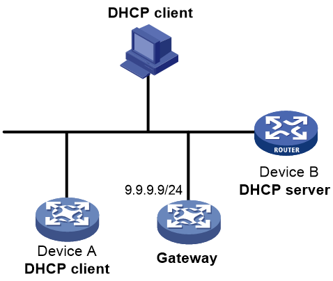
As shown in Figure 1, Device A acts as the DHCP client, and Device B acts as the DHCP server. Device A automatically obtains IP address and gateway address 9.9.9.9/24 from Device B. After you configure a static route on Device A whose next hop is the DHCP-designated gateway, Device A will generate a static route with gateway address 9.9.9.9/24 as its next hop address. If the gateway address changes, the next hop address of the static route will change to the new gateway address accordingly.
Figure 1 Configuring the DHCP-designated default router as the next hop of a static route
For more information about DHCP, see DHCP in Layer 3—IP Services Configuration Guide.
Restrictions and guidelines
When you configure the next hop of a static route as the DHCP-designated default router, make sure the output interface of the static route is a broadcast interface.
Procedure
1. Enter system view.
system-view
2. Configure a static route and specify the default router designated by the DHCP server for the output interface as the next hop of the static route.
Public network:
ip route-static { dest-address { mask-length | mask } | group group-name } interface-type interface-number dhcp [ backup-interface interface-type interface-number [ backup-nexthop backup-nexthop-address ] [ permanent ] | permanent | track track-entry-number ] [ cost cost-value ] [ preference preference ] [ tag tag-value ] [ no-advertise ] [ description text ]
VPN:
ip route-static vpn-instance s-vpn-instance-name dest-address { mask-length | mask } interface-type interface-number dhcp [ backup-interface interface-type interface-number [ backup-nexthop backup-nexthop-address ] [ permanent ] | permanent | track track-entry-number ] [ cost cost-value ] [ preference preference ] [ tag tag-value ] [ no-advertise ] [ description text ]
ip route-static vpn-instance s-vpn-instance-name group group-name interface-type interface-number dhcp [ backup-interface interface-type interface-number [ backup-nexthop backup-nexthop-address ] [ permanent ] ] [ cost cost-value ] [ preference preference ] [ tag tag-value ] [ no-advertise ] [ description text ]
By default, no static route is configured with the DHCP-designated default router as the next hop.
Configuring a floating static route
About this task
A floating static route can implement route backup to improve network reliability.
When a static or dynamic route to a destination address already exists on the device, you can configure another static route with lower priority as the backup route. This backup static route is called a floating static route. It is activated only when the primary route becomes unavailable. After the primary route recovers, the floating static route becomes inactive, and data forwarding switches back to the primary route.
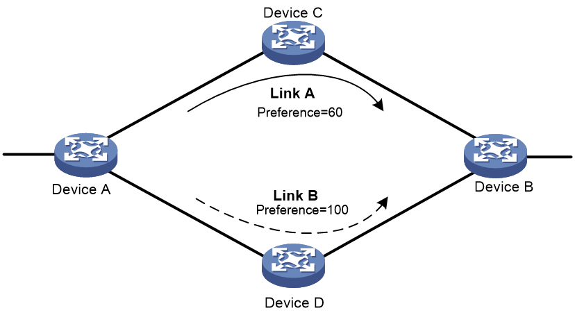
As shown in Figure 2, two links exist between Device A and Device B. On device A, configure a static route with next hop Device C and preference 60, and configure a static route with next hop Device D and preference 100. The static route with next hop Device D automatically becomes a floating static route.
Figure 2 Configuring a floating static route
Procedure
You can configure a floating static route in either of the following ways:
· Configure different priorities for multiple static routes to the same destination address. The route with lower priority automatically becomes the floating static route.
· When a route to a destination address already exists on the device, configure a static route with a lower priority to the same destination address.
When you configure a floating static route, set a larger priority value for the route than the priority value of the primary route. For more information, see "Configuring a static route."
Deleting static routes
About this task
To delete a static route, use the undo ip route-static command. To delete all static routes including the default route, use the delete static-routes all command.
Procedure
1. Enter system view.
system-view
2. Delete all static routes.
Public network:
delete static-routes all
VPN:
delete vpn-instance vpn-instance-name static-routes all
|
|
CAUTION: This command might interrupt network communication and cause packet forwarding failure. Before executing the command, make sure you fully understand the potential impact on the network. |
Configuring BFD for static routes
|
|
IMPORTANT: Enabling BFD for a flapping route could worsen the situation. |
About BFD
BFD provides a general-purpose, standard, medium-, and protocol-independent fast failure detection mechanism. It can uniformly and quickly detect the failures of the bidirectional forwarding paths between two routers for protocols, such as routing protocols and MPLS. This feature allows you to associate a BFD session with a static route, and use the BFD session state to monitor the state of the link associated with the IPv4 static route. When the BFD session detects a link failure (BFD session state is Down) on the IPv4 static route, BFD reports the failure to the system, and the system then removes this route from the IP routing table. When the BFD session detects that the previously failed link is re-established successfully (BFD session state is Up), BFD reports this event to the system, and the system then adds this route back to the IP routing table.
For more information about BFD, see High Availability Configuration Guide.
Configuring BFD control packet mode
About this task
This mode uses BFD control packets to detect the status of a link bidirectionally at a millisecond level.
BFD control packet mode can be applied to static routes with a direct next hop or with an indirect next hop.
Restrictions and guidelines for BFD control packet mode
If you use BFD control packet mode at the local end, you must use this mode also at the peer end.
Configuring BFD control packet mode for a static route (direct next hop)
1. Enter system view.
system-view
2. Configure BFD control packet mode for a static route.
Public network:
ip route-static dest-address { mask-length | mask } interface-type interface-number next-hop-address bfd { control-packet | static session-name } [ cost cost-value ] [ preference preference ] [ tag tag-value ] [ description text ]
VPN:
ip route-static vpn-instance s-vpn-instance-name dest-address { mask-length | mask } interface-type interface-number next-hop-address bfd { control-packet | static session-name } [ cost cost-value ] [ preference preference ] [ tag tag-value ] [ description text ]
By default, BFD control packet mode for a static route is not configured.
If the action of a PBR node specifies only the default next hop and default SRv6 TE policy for packets, follow these restrictions and guidelines when executing this command:
¡ You cannot configure static routes for the VPN instance in the match criteria of the PBR node.
¡ The dest-address argument cannot specify the destination IP address in the match criteria of the PBR node.
For more information about PBR, see "Configuring PBR."
3. (Optional.) Configure BFD session parameters for the static route.
ip route-static bfd interface-type interface-number next-hop-address { detect-multiplier detect-multiplier | min-receive-interval min-receive-interval | min-transmit-interval min-transmit-interval } *
By default, no BFD session parameters are specifically configured for a static route. The static route uses the session parameters configured for the BFD module (common BFD session parameters).
Configuring BFD control packet mode for a static route (indirect next hop)
1. Enter system view.
system-view
2. Configure BFD control packet mode for a static route.
Public network:
ip route-static dest-address { mask-length | mask } { next-hop-address bfd control-packet bfd-source ip-address | vpn-instance d-vpn-instance-name next-hop-address bfd { control-packet bfd-source ip-address | static session-name } } [ cost cost-value | inherit-cost ] [ preference preference ] [ tag tag-value ] [ description text ]
VPN:
ip route-static vpn-instance s-vpn-instance-name dest-address { mask-length | mask } { next-hop-address bfd { control-packet bfd-source ip-address | static session-name } | vpn-instance d-vpn-instance-name next-hop-address bfd { control-packet bfd-source ip-address | static session-name } } [ cost cost-value | inherit-cost ] [ preference preference ] [ tag tag-value ] [ description text ]
By default, BFD control packet mode for a static route is not configured.
If a VPN instance has been specified as the destination VPN instance, you cannot specify the vpn-instance d-vpn-instance-name option when configuring a static route for the VPN instance by using this command.
A static route with a destination VPN instance specified supports only VXLAN tunnels.
If the action of a PBR node specifies only the default next hop and default SRv6 TE policy for packets, follow these restrictions and guidelines when executing this command:
¡ You cannot configure static routes for the VPN instance in the match criteria of the PBR node.
¡ The dest-address argument cannot specify the destination IP address in the match criteria of the PBR node.
For more information about PBR, see "Configuring PBR."
3. (Optional.) Configure BFD session parameters for the static route.
ip route-static bfd [ vpn-instance d-vpn-instance-name ] next-hop-address source-ip ip-address { detect-multiplier detect-multiplier | min-receive-interval min-receive-interval | min-transmit-interval min-transmit-interval } *
By default, no BFD session parameters are specifically configured for a static route. The static route uses the session parameters configured for the BFD module (common BFD session parameters).
Configuring BFD echo packet mode
About this task
With BFD echo packet mode enabled for a static route, the output interface sends BFD echo packets to the destination device, which loops the packets back to test the link reachability.
Restrictions and guidelines
|
|
IMPORTANT: Do not use BFD for a static route with the output interface in spoofing state. |
You do not need to configure BFD echo packet mode at the peer end.
Procedure
1. Enter system view.
system-view
2. (Optional.) Configure the source address of echo packets.
bfd echo-source-ip ip-address
By default, the source address of echo packets is not configured.
As a best practice to avoid network congestion caused by excessive ICMP redirect packets from the peer, use this command. Make sure the source IPv4 address is not on the subnet of any interfaces on the device.
For more information about this command, see BFD in High Availability Command Reference.
3. Configure BFD echo packet mode for a static route.
Public network:
ip route-static dest-address { mask-length | mask } interface-type interface-number next-hop-address bfd { echo-packet | static session-name } [ cost cost-value ] [ preference preference ] [ tag tag-value ] [ description text ]
VPN:
ip route-static vpn-instance s-vpn-instance-name dest-address { mask-length | mask } interface-type interface-number next-hop-address bfd { echo-packet | static session-name } [ cost cost-value ] [ preference preference ] [ tag tag-value ] [ description text ]
By default, BFD echo packet mode for a static route is not configured.
If the action of a PBR node specifies only the default next hop and default SRv6 TE policy for packets, follow these restrictions and guidelines when executing this command:
¡ You cannot configure static routes for the VPN instance in the match criteria of the PBR node.
¡ The dest-address argument cannot specify the destination IP address in the match criteria of the PBR node.
For more information about PBR, see "Configuring PBR.
4. (Optional.) Configure BFD session parameters for the static route.
ip route-static bfd interface-type interface-number next-hop-address { detect-multiplier detect-multiplier | min-echo-receive-interval min-echo-receive-interval } *
By default, no BFD session parameters are specifically configured for a static route. The static route uses the session parameters configured for the BFD module (common BFD session parameters).
Configuring static route FRR
About static route FRR
A link or router failure on a path can cause packet loss. Static route fast reroute (FRR) enables fast rerouting to minimize the impact of link or node failures.
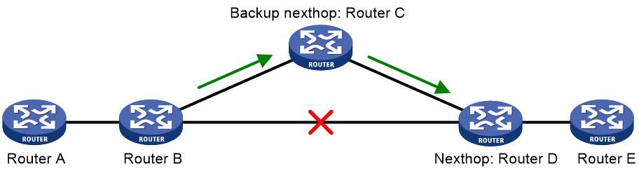
As shown in Figure 3, upon a link failure, packets are directed to the backup next hop to avoid traffic interruption. You can either specify a backup next hop for FRR or enable FRR to automatically select a backup next hop (which must be configured in advance).
Restrictions and guidelines for static route FRR
· Do not use static route FRR and BFD (for a static route) at the same time.
· If the device has multiple optimal routes with the same preference, these routes form ECMP routes, and this feature cannot find the backup next hop for them.
· Besides the configured static route for FRR, the device must have another route to reach the destination.
When the state of the primary link (with Layer 3 interfaces staying up) changes from bidirectional to unidirectional or down, static route FRR quickly redirects traffic to the backup next hop. When the Layer 3 interfaces of the primary link are down, static route FRR temporarily redirects traffic to the backup next hop. In addition, the device searches for another route to reach the destination and redirects traffic to the new path if a route is found. If no route is found, traffic interruption occurs.
Configuring static route FRR by specifying a backup next hop
About this task
After you configure this feature, the backup output interface and backup next hop will be issued to the forwarding table together with the primary output interface and primary next hop of the static route. To view the backup output interface and backup next hop of the static route, use the display route-static routing-table command.
Restrictions and guidelines
A static route does not take effect when the backup output interface is unavailable.
To change the backup output interface or next hop, you must first remove the current setting. The backup output interface and next hop must be different from the primary output interface and next hop.
Procedure
1. Enter system view.
system-view
2. Configure static route FRR.
Public network:
ip route-static dest-address { mask-length | mask } interface-type interface-number [ next-hop-address [ backup-interface interface-type interface-number [ backup-nexthop backup-nexthop-address ] ] ] [ permanent ] [ cost cost-value ] [ preference preference ] [ tag tag-value ] [ description text ]
VPN:
ip route-static vpn-instance s-vpn-instance-name dest-address { mask-length | mask } interface-type interface-number [ next-hop-address [ backup-interface interface-type interface-number [ backup-nexthop backup-nexthop-address ] ] ] [ permanent ] [ cost cost-value ] [ preference preference ] [ tag tag-value ] [ description text ]
If the action of a PBR node specifies only the default next hop and default SRv6 TE policy for packets, follow these restrictions and guidelines when executing this command:
¡ You cannot configure static routes for the VPN instance in the match criteria of the PBR node.
¡ The dest-address argument cannot specify the destination IP address in the match criteria of the PBR node.
For more information about PBR, see "Configuring PBR."
By default, static route FRR is disabled.
Configuring static route FRR to automatically select a backup next hop
About this task
If multiple static routes to the same destination address with different priorities exist on the device, you can use perform this task to enable the device to automatically obtain backup routes. Both the primary and backup routes will be issued to the forwarding table. The route with higher priority is the primary route, and the route with lower priority is the backup route.
Procedure
1. Enter system view.
system-view
2. Configure static route FRR to automatically select a backup next hop.
ip route-static fast-reroute auto
By default, static route FRR is disabled from automatically selecting a backup next hop.
Configuring BFD to detect next hop reachability for the primary link of static route FRR
About this task
By default, static route FRR uses ARP to detect primary link failures. With this feature configured, the device automatically creates a BFD session of the IP FRR protocol type, and uses this BFD session to detect next hop reachability of the primary route. This can reduce the convergence time upon traffic switchover to the backup route next hop when the primary route next hop becomes unavailable.
Restrictions and guidelines
If you do not configure static route FRR, or no reachable backup next hops are available for FRR, the device cannot establish a BFD session to detect the primary route next hop.
To use the BFD session in echo packet mode to detect next hop reachability of the primary route, you only need to configure the BFD echo packet mode on the local end.
The BFD session in control packet mode can be successfully established only through negotiation between the two ends. To use the BFD session in control packet mode to detect next hop reachability of the primary route, perform one of the following tasks:
· Configure the ip route-static primary-path-detect bfd command on the peer device of the primary link. This method applies when FRR is configured for both ends of the primary link.
· Manually create a static BFD session on the peer device of the primary link, and configure the following settings for the static BFD session:
¡ Specify the source IP address for the static BFD session as the destination IP address of the BFD session automatically created on the local end.
¡ Specify the destination IP address for the static BFD session as the source IP address of the BFD session automatically created on the local end.
¡ Specify the remote discriminator for the static BFD session as the local discriminator of the BFD session automatically created on the local end.
Procedure
1. Enter system view.
system-view
2. (Optional.) Configure the source IP address of BFD echo packets.
bfd echo-source-ip ip-address
By default, the source IP address of BFD echo packets is not configured.
This command is required for only the BFD session in echo packet mode.
As a best practice to avoid network congestion caused by excessive ICMP redirect packets from the peer, use this command. Make sure the source IPv4 address is not on the subnet of any interfaces on the device.
For more information about this command, see BFD in High Availability Command Reference.
3. Configure BFD to detect next hop reachability for the primary link of static route FRR.
ip route-static primary-path-detect bfd { ctrl | echo }
By default, BFD is not configured to detect next hop reachability for the primary link of static route FRR. The static route uses ARP to detect next hop reachability of the primary route.
Allowing static routes to inherit the SRv6 SID information of related routes in route recursion
About this task
A static route requires route recursion if its next hop is not directly connected. If the next hop recurses to an SRv6 BE or SRv6 TE policy path, the static route does not inherit the SRv6 SID information of the related route by default. The device does not add SRv6 SID information to the packets matching this static route.
After you configure this feature, if the next hop of the static route recurses to an SRv6 BE or SRv6 TE policy path, the static route inherits the SRv6 SID information of related route. The device will add SRv6 SID information and SRv6 encapsulation to the packets matching this static route, and then forward the encapsulated packets in SRv6 BE mode or through the SRv6 TE policy.
For more information about SRv6 BE, see IP L3VPN over SRv6 configuration or public network IP over SRv6 configuration in Segment Routing Configuration Guide. For more information about SRv6 TE policies, see SRv6 TE policy configuration in Segment Routing Configuration Guide.
Procedure
1. Enter system view.
system-view
2. Allow IPv4 static routes to inherit the SRv6 SID information of related routes in route recursion.
ip route-static recursive-lookup segment-routing-ipv6
By default, IPv4 static routes are not allowed to inherit the SRv6 SID information of related routes in route recursion.
Allowing static routes to recurse to LSP tunnels
About this task
Devices in the service provider network will learn a large number of routes if they perform IP forwarding for all customer network packets. To conserve resources on the devices, use this feature on the device through which customer network users access the service provider network. This feature allows static routes to recurse to LSP tunnels. As a result, devices in the provider network will forward customer network IP packets based on labels, without the need to learn customer network routes.
This feature allows a device to preferentially recurse static routes to LSP tunnels. If a static route cannot recurse to an LSP tunnel, the device recurses the static route to an output interface and next hop.
Procedure
1. Enter system view.
system-view
2. Enable the device to recurse static routes to LSP tunnels.
ip route-static recursive-lookup tunnel [ prefix-list ipv4-prefix-list-name ] [ tunnel-policy tunnel-policy-name ]
By default, static routes cannot recurse to LSP tunnels.
Display and maintenance commands for static routing
Execute display commands in any view.
|
Task |
Command |
|
Display static route information. |
display ip routing-table protocol static [ inactive | verbose ] |
|
Display static route next hop information. |
display route-static nib [ nib-id ] [ verbose ] |
|
Display static routing table information. |
display route-static routing-table [ vpn-instance vpn-instance-name ] [ ip-address { mask-length | mask } ] |
Static route configuration examples
Example: Configuring basic static routes
Network configuration
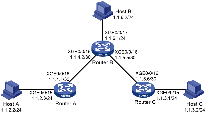
As shown in Figure 4, configure static routes on the routers for interconnections between any two hosts.
Procedure
1. Configure IP addresses for interfaces. (Details not shown.)
2. Configure static routes:
# Configure a default route on Router A.
<RouterA> system-view
[RouterA] ip route-static 0.0.0.0 0.0.0.0 1.1.4.2
# Configure two static routes on Router B.
<RouterB> system-view
[RouterB] ip route-static 1.1.2.0 255.255.255.0 1.1.4.1
[RouterB] ip route-static 1.1.3.0 255.255.255.0 1.1.5.6
# Configure a default route on Router C.
<RouterC> system-view
[RouterC] ip route-static 0.0.0.0 0.0.0.0 1.1.5.5
3. Configure the default gateways of Host A, Host B, and Host C as 1.1.2.3, 1.1.6.1, and 1.1.3.1. (Details not shown.)
Verifying the configuration
# Display the static route information on Router A.
[RouterA] display ip routing-table protocol static
Summary Count : 1
Static Routing table Status : <Active>
Summary Count : 1
Destination/Mask Proto Pre Cost NextHop Interface
0.0.0.0/0 Static 60 0 1.1.4.2 XGE0/0/16
Static Routing table Status : <Inactive>
Summary Count : 0
# Display the static route information on Router B.
[RouterB] display ip routing-table protocol static
Summary Count : 2
Static Routing table Status : <Active>
Summary Count : 2
Destination/Mask Proto Pre Cost NextHop Interface
1.1.2.0/24 Static 60 0 1.1.4.1 XGE0/0/15
1.1.3.0/24 Static 60 0 1.1.5.6 XGE0/0/16
Static Routing table Status : <Inactive>
Summary Count : 0
# Use the ping command on Host B to test the reachability of Host A (Windows XP runs on the two hosts).
C:\Documents and Settings\Administrator>ping 1.1.2.2
Pinging 1.1.2.2 with 32 bytes of data:
Reply from 1.1.2.2: bytes=32 time=1ms TTL=126
Reply from 1.1.2.2: bytes=32 time=1ms TTL=126
Reply from 1.1.2.2: bytes=32 time=1ms TTL=126
Reply from 1.1.2.2: bytes=32 time=1ms TTL=126
Ping statistics for 1.1.2.2:
Packets: Sent = 4, Received = 4, Lost = 0 (0% loss),
Approximate round trip times in milli-seconds:
Minimum = 1ms, Maximum = 1ms, Average = 1ms
# Use the tracert command on Host B to test the reachability of Host A.
C:\Documents and Settings\Administrator>tracert 1.1.2.2
Tracing route to 1.1.2.2 over a maximum of 30 hops
1 <1 ms <1 ms <1 ms 1.1.6.1
2 <1 ms <1 ms <1 ms 1.1.4.1
3 1 ms <1 ms <1 ms 1.1.2.2
Trace complete.
Example: Configuring BFD for static routes (direct next hop)
Network configuration
Configure the following, as shown in Figure 5:
· Configure a static route to subnet 120.1.1.0/24 on Router A.
· Configure a static route to subnet 121.1.1.0/24 on Router B.
· Enable BFD for both routes.
· Configure a static route to subnet 120.1.1.0/24 and a static route to subnet 121.1.1.0/24 on Router C.
When the link between Router A and Router B through the Layer 2 switch fails, BFD can detect the failure immediately. Router A then communicates with Router B through Router C.
Figure 5 Network diagram
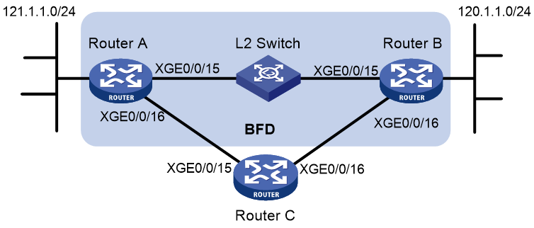
Table 1 Interface and IP address assignment
|
Device |
Interface |
IP address |
|
Router A |
Ten-GigabitEthernet 0/0/15 |
12.1.1.1/24 |
|
Router A |
Ten-GigabitEthernet 0/0/16 |
10.1.1.102/24 |
|
Router B |
Ten-GigabitEthernet 0/0/15 |
12.1.1.2/24 |
|
Router B |
Ten-GigabitEthernet 0/0/16 |
13.1.1.1/24 |
|
Router C |
Ten-GigabitEthernet 0/0/15 |
10.1.1.100/24 |
|
Router C |
Ten-GigabitEthernet 0/0/16 |
13.1.1.2/24 |
Procedure
1. Configure IP addresses for interfaces. (Details not shown.)
2. Configure static routes and BFD:
# Configure static routes on Route A and enable BFD control packet mode for the static route that traverses the Layer 2 switch.
<RouterA> system-view
[RouterA] interface ten-gigabitethernet 0/0/15
[RouterA-Ten-GigabitEthernet0/0/15] bfd min-transmit-interval 500
[RouterA-Ten-GigabitEthernet0/0/15] bfd min-receive-interval 500
[RouterA-Ten-GigabitEthernet0/0/15] bfd detect-multiplier 9
[RouterA-Ten-GigabitEthernet0/0/15] quit
[RouterA] ip route-static 120.1.1.0 24 ten-gigabitethernet 0/0/15 12.1.1.2 bfd control-packet
[RouterA] ip route-static 120.1.1.0 24 ten-gigabitethernet 0/0/16 10.1.1.100 preference 65
[RouterA] quit
# Configure static routes on Router B and enable BFD control packet mode for the static route that traverses the Layer 2 switch.
<RouterB> system-view
[RouterB] interface ten-gigabitethernet 0/0/15
[RouterB-Ten-GigabitEthernet0/0/15] bfd min-transmit-interval 500
[RouterB-Ten-GigabitEthernet0/0/15] bfd min-receive-interval 500
[RouterB-Ten-GigabitEthernet0/0/15] bfd detect-multiplier 9
[RouterB-Ten-GigabitEthernet0/0/15] quit
[RouterB] ip route-static 121.1.1.0 24 ten-gigabitethernet 0/0/15 12.1.1.1 bfd control-packet
[RouterB] ip route-static 121.1.1.0 24 ten-gigabitethernet 0/0/16 13.1.1.2 preference 65
[RouterB] quit
# Configure static routes on Router C.
<RouterC> system-view
[RouterC] ip route-static 120.1.1.0 24 13.1.1.1
[RouterC] ip route-static 121.1.1.0 24 10.1.1.102
Verifying the configuration
# Display BFD sessions on Router A.
<RouterA> display bfd session
Total sessions: 1 Up sessions: 1 Init mode: Active
IPv4 session working in control packet mode:
LD/RD SourceAddr DestAddr State Holdtime Interface
4/7 12.1.1.1 12.1.1.2 Up 2000ms XGE0/0/15
The output shows that the BFD session has been created.
# Display static routes on Router A.
<RouterA> display ip routing-table protocol static
Summary Count : 1
Static Routing table Status : <Active>
Summary Count : 1
Destination/Mask Proto Pre Cost NextHop Interface
120.1.1.0/24 Static 60 0 12.1.1.2 XGE0/0/15
Static Routing table Status : <Inactive>
Summary Count : 0
The output shows that Router A communicates with Router B through Ten-GigabitEthernet 0/0/15. Then the link over Ten-GigabitEthernet 0/0/15 fails.
# Display static routes on Router A.
<RouterA> display ip routing-table protocol static
Summary Count : 1
Static Routing table Status : <Active>
Summary Count : 1
Destination/Mask Proto Pre Cost NextHop Interface
120.1.1.0/24 Static 65 0 10.1.1.100 XGE0/0/16
Static Routing table Status : <Inactive>
Summary Count : 0
The output shows that Router A communicates with Router B through Ten-GigabitEthernet 0/0/16.
Example: Configuring BFD for static routes (indirect next hop)
Network configuration
Figure 6 shows the network topology as follows:
· Router A has a route to interface Loopback 1 (2.2.2.9/32) on Router B, with the output interface Ten-GigabitEthernet 0/0/15.
· Router B has a route to interface Loopback 1 (1.1.1.9/32) on Router A, with the output interface Ten-GigabitEthernet 0/0/15.
· Router D has a route to 1.1.1.9/32, with the output interface Ten-GigabitEthernet 0/0/15, and a route to 2.2.2.9/32, with the output interface Ten-GigabitEthernet 0/0/16.
Configure the following:
· Configure a static route to subnet 120.1.1.0/24 on Router A.
· Configure a static route to subnet 121.1.1.0/24 on Router B.
· Enable BFD for both routes.
· Configure a static route to subnet 120.1.1.0/24 and a static route to subnet 121.1.1.0/24 on both Router C and Router D.
When the link between Router A and Router B through Router D fails, BFD can detect the failure immediately. Router A then communicates with Router B through Router C.
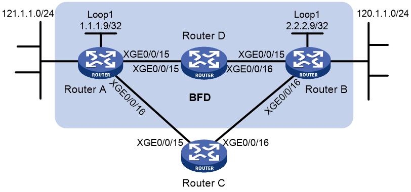
Table 2 Interface and IP address assignment
|
Device |
Interface |
IP address |
|
Router A |
Ten-GigabitEthernet 0/0/15 |
12.1.1.1/24 |
|
Router A |
Ten-GigabitEthernet 0/0/16 |
10.1.1.102/24 |
|
Router A |
Loopback 1 |
1.1.1.9/32 |
|
Router B |
Ten-GigabitEthernet 0/0/15 |
11.1.1.2/24 |
|
Router B |
Ten-GigabitEthernet 0/0/16 |
13.1.1.1/24 |
|
Router B |
Loopback 1 |
2.2.2.9/32 |
|
Router C |
Ten-GigabitEthernet 0/0/15 |
10.1.1.100/24 |
|
Router C |
Ten-GigabitEthernet 0/0/16 |
13.1.1.2/24 |
|
Router D |
Ten-GigabitEthernet 0/0/15 |
12.1.1.2/24 |
|
Router D |
Ten-GigabitEthernet 0/0/16 |
11.1.1.2/24 |
Procedure
1. Configure IP addresses for interfaces. (Details not shown.)
2. Configure static routes and BFD:
# Configure static routes on Router A and enable BFD control packet mode for the static route that traverses Router D.
<RouterA> system-view
[RouterA] bfd multi-hop min-transmit-interval 500
[RouterA] bfd multi-hop min-receive-interval 500
[RouterA] bfd multi-hop detect-multiplier 9
[RouterA] ip route-static 2.2.2.9 32 12.1.1.2
[RouterA] ip route-static 120.1.1.0 24 2.2.2.9 bfd control-packet bfd-source 1.1.1.9
[RouterA] ip route-static 120.1.1.0 24 ten-gigabitethernet 0/0/16 10.1.1.100 preference 65
[RouterA] quit
# Configure static routes on Router B and enable BFD control packet mode for the static route that traverses Router D.
<RouterB> system-view
[RouterB] bfd multi-hop min-transmit-interval 500
[RouterB] bfd multi-hop min-receive-interval 500
[RouterB] bfd multi-hop detect-multiplier 9
[RouterB] ip route-static 1.1.1.9 32 11.1.1.1
[RouterB] ip route-static 121.1.1.0 24 1.1.1.9 bfd control-packet bfd-source 2.2.2.9
[RouterB] ip route-static 121.1.1.0 24 ten-gigabitethernet 0/0/16 13.1.1.2 preference 65
[RouterB] quit
# Configure static routes on Router C.
<RouterC> system-view
[RouterC] ip route-static 120.1.1.0 24 13.1.1.1
[RouterC] ip route-static 121.1.1.0 24 10.1.1.102
# Configure static routes on Router D.
<RouterD> system-view
[RouterD] ip route-static 120.1.1.0 24 11.1.1.2
[RouterD] ip route-static 121.1.1.0 24 12.1.1.1
Verifying the configuration
# Display the BFD session information on Router A.
<RouterA> display bfd session
Total sessions: 1 Up sessions: 1 Init mode: Active
IPv4 session working in control packet mode:
LD/RD SourceAddr DestAddr State Holdtime Interface
4/7 1.1.1.9 2.2.2.9 Up 2000ms N/A
The output shows that the BFD session has been created.
# Display static routes on Router A.
<RouterA> display ip routing-table protocol static
Summary Count : 1
Static Routing table Status : <Active>
Summary Count : 1
Destination/Mask Proto Pre Cost NextHop Interface
120.1.1.0/24 Static 60 0 12.1.1.2 XGE0/0/15
Static Routing table Status : <Inactive>
Summary Count : 0
The output shows that Router A communicates with Router B through Ten-GigabitEthernet 0/0/15. Then the link over Ten-GigabitEthernet 0/0/15 fails.
# Display static routes on Router A.
<RouterA> display ip routing-table protocol static
Summary Count : 1
Static Routing table Status : <Active>
Summary Count : 1
Destination/Mask Proto Pre Cost NextHop Interface
120.1.1.0/24 Static 65 0 10.1.1.100 XGE0/0/16
Static Routing table Status : <Inactive>
Summary Count : 0
The output shows that Router A communicates with Router B through Ten-GigabitEthernet 0/0/16.
Example: Configuring static route FRR
Network configuration
As shown in Figure 7, configure static routes on Router A, Router B, and Router C, and configure static route FRR. When Link A becomes unidirectional, traffic can be switched to Link B immediately.
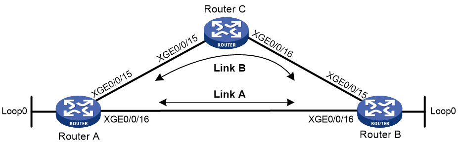
Table 3 Interface and IP address assignment
|
Device |
Interface |
IP address |
|
Router A |
Ten-GigabitEthernet 0/0/15 |
12.12.12.1/24 |
|
Router A |
Ten-GigabitEthernet 0/0/16 |
13.13.13.1/24 |
|
Router A |
Loopback 0 |
1.1.1.1/32 |
|
Router B |
Ten-GigabitEthernet 0/0/15 |
24.24.24.4/24 |
|
Router B |
Ten-GigabitEthernet 0/0/16 |
13.13.13.2/24 |
|
Router B |
Loopback 0 |
4.4.4.4/32 |
|
Router C |
Ten-GigabitEthernet 0/0/15 |
12.12.12.2/24 |
|
Router C |
Ten-GigabitEthernet 0/0/16 |
24.24.24.2/24 |
Procedure
1. Configure IP addresses for interfaces. (Details not shown.)
2. Configure static route FRR on link A:
Choose one of the following methods:
¡ (Method 1.) Specify a backup next hop for static route FRR:
# Configure a static route on Router A, and specify Ten-GigabitEthernet 0/0/15 as the backup output interface and 12.12.12.2 as the backup next hop.
<RouterA> system-view
[RouterA] ip route-static 4.4.4.4 32 ten-gigabitethernet 0/0/16 13.13.13.2 backup-interface ten-gigabitethernet 0/0/15 backup-nexthop 12.12.12.2
# Configure a static route on Router B, and specify Ten-GigabitEthernet 0/0/15 as the backup output interface and 24.24.24.2 as the backup next hop.
<RouterB> system-view
[RouterB] ip route-static 1.1.1.1 32 ten-gigabitethernet 0/0/16 13.13.13.1 backup-interface ten-gigabitethernet 0/0/15 backup-nexthop 24.24.24.2
¡ (Method 2.) Configure static route FRR to automatically select a backup next hop:
# Configure static routes on Router A, and enable static route FRR.
<RouterA> system-view
[RouterA] ip route-static 4.4.4.4 32 ten-gigabitethernet 0/0/16 13.13.13.2
[RouterA] ip route-static 4.4.4.4 32 ten-gigabitethernet 0/0/15 12.12.12.2 preference 70
[RouterA] ip route-static fast-reroute auto
# Configure static routes on Router B, and enable static route FRR.
<RouterB> system-view
[RouterB] ip route-static 1.1.1.1 32 ten-gigabitethernet 0/0/16 13.13.13.1
[RouterB] ip route-static 1.1.1.1 32 ten-gigabitethernet 0/0/15 24.24.24.2 preference 70
[RouterB] ip route-static fast-reroute auto
3. Configure static routes on Router C.
<RouterC> system-view
[RouterC] ip route-static 4.4.4.4 32 ten-gigabitethernet 0/0/16 24.24.24.4
[RouterC] ip route-static 1.1.1.1 32 ten-gigabitethernet 0/0/15 12.12.12.1
Verifying the configuration
# Display route 4.4.4.4/32 on Router A to view the backup next hop information.
[RouterA] display ip routing-table 4.4.4.4 verbose
Summary Count : 1
Destination: 4.4.4.4/32
Protocol: Static
Process ID: 0
SubProtID: 0x0 Age: 04h20m37s
FlushedAge: 15h28m49s
Cost: 0 Preference: 60
IpPre: N/A QosLocalID: N/A
Tag: 0 State: Active Adv
OrigTblID: 0x0 OrigVrf: default-vrf
TableID: 0x2 OrigAs: 0
NibID: 0x26000002 LastAs: 0
AttrID: 0xffffffff
BkAttrID: 0xffffffff Neighbor: 0.0.0.0
Flags: 0x1008c OrigNextHop: 13.13.13.2
Label: NULL RealNextHop: 13.13.13.2
BkLabel: NULL BkNextHop: 12.12.12.2
SRLabel: NULL Interface: Ten-GigabitEthernet0/0/16
BkSRLabel: NULL BkInterface: Ten-GigabitEthernet0/0/15
Tunnel ID: Invalid IPInterface: Ten-GigabitEthernet0/0/16
BkTunnel ID: Invalid BkIPInterface: Ten-GigabitEthernet0/0/15
InLabel: NULL ColorInterface: N/A
SIDIndex: NULL BkColorInterface: N/A
FtnIndex: 0x0 TunnelInterface: N/A
TrafficIndex: N/A BkTunnelInterface: N/A
Connector: N/A PathID: 0x0
UserID: 0x0 SRTunnelID: Invalid
SID Type: N/A NID: Invalid
FlushNID: Invalid BkNID: Invalid
BkFlushNID: Invalid StatFlags: 0x0
SID: N/A
BkSID: N/A
CommBlockLen: 0 Priority: Critical
MemberPort: N/A ExtFlags: 0x0
UCMIndex: 0x0 UserVLAN: 65535
UCMMTU: 0 BrasHash: 0
SessionID: 0 UserGroupID: 0
IsoGroupID: 0 BkIsoGroupID: 0
# Display route 1.1.1.1/32 on Router B to view the backup next hop information.
[RouterB] display ip routing-table 1.1.1.1 verbose
Summary Count : 1
Destination: 1.1.1.1/32
Protocol: Static
Process ID: 0
SubProtID: 0x0 Age: 04h20m37s
FlushedAge: 15h28m49s
Cost: 0 Preference: 10
IpPre: N/A QosLocalID: N/A
Tag: 0 State: Active Adv
OrigTblID: 0x0 OrigVrf: default-vrf
TableID: 0x2 OrigAs: 0
NibID: 0x26000002 LastAs: 0
AttrID: 0xffffffff
BkAttrID: 0xffffffff Neighbor: 0.0.0.0
Flags: 0x1008c OrigNextHop: 13.13.13.1
Label: NULL RealNextHop: 13.13.13.1
BkLabel: NULL BkNextHop: 24.24.24.2
SRLabel: NULL Interface: Ten-GigabitEthernet0/0/16
BkSRLabel: NULL BkInterface: Ten-GigabitEthernet0/0/15
Tunnel ID: Invalid IPInterface: Ten-GigabitEthernet0/0/16
BkTunnel ID: Invalid BkIPInterface: Ten-GigabitEthernet0/0/15
InLabel: NULL ColorInterface: N/A
SIDIndex: NULL BkColorInterface: N/A
FtnIndex: 0x0 TunnelInterface: N/A
TrafficIndex: N/A BkTunnelInterface: N/A
Connector: N/A PathID: 0x0
UserID: 0x0 SRTunnelID: Invalid
SID Type: N/A NID: Invalid
FlushNID: Invalid BkNID: Invalid
BkFlushNID: Invalid StatFlags: 0x0
SID: N/A
BkSID: N/A
CommBlockLen: 0 Priority: Critical
MemberPort: N/A ExtFlags: 0x0
UCMIndex: 0x0 UserVLAN: 65535
UCMMTU: 0 BrasHash: 0
SessionID: 0 UserGroupID: 0
IsoGroupID: 0 BkIsoGroupID: 0
Configuring a default route
A default route is used to forward packets that do not match any specific routing entry in the routing table. Without a default route, packets that do not match any routing entries are discarded and an ICMP destination-unreachable packet is sent to the source.
A default route can be configured in either of the following ways:
· The network administrator can configure a default route with both destination and mask being 0.0.0.0. For more information, see "Configuring static routing."
· Some dynamic routing protocols can generate a default route. For example, an upstream router running OSPF can generate a default route and advertise it to other routers. These routers install the default route with the next hop being the upstream router. For more information, see the respective chapters on these routing protocols in this configuration guide.
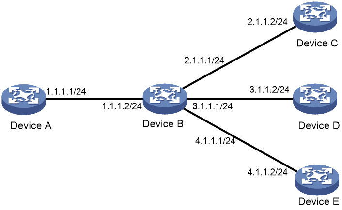
As shown in Figure 8, Device B is the next hop for packets from Device A to Device C, Device D, and Device E. You can configure a default route on Device A to replace the three static routes from Device A to Device C, Device D, and Device E. Then, packets that do not match any other routes will be forwarded based on the default route.
The next hop address, destination address, and subnet mask of the default route configured on Device A are 1.1.1.2, 0.0.0.0, and 0.0.0.0, respectively.
Figure 8 Configuring a default route