- Table of Contents
-
- 08-Radio Resources Management Configuration Guide
- 00-Preface
- 01-Radio management configuration
- 02-WLAN radio load balancing configuration
- 03-WLAN load balancing configuration
- 04-WLAN radio resource measurement configuration
- 05-Band navigation configuration
- 06-WLAN RRM configuration
- 07-Channel scanning configuration
- 08-Spectrum management configuration
- Related Documents
-
| Title | Size | Download |
|---|---|---|
| 06-WLAN RRM configuration | 267.12 KB |
Setting the channel calibration interval for auto-DFS
Configuring DFS trigger parameters
Configuring radar detection-triggered RRM
Setting the power calibration interval for auto-TPC
Configuring TPC trigger parameters
Configuring automatic bandwidth adjustment
Enabling automatic bandwidth adjustment
Setting the interval for automatic bandwidth adjustment
Enabling SNMP notifications for WLAN RRM
Display and maintenance commands for WLAN RRM
WLAN RRM configuration examples
Example: Configuring periodic auto-DFS
Configuring WLAN RRM
About WLAN RRM
WLAN Radio Resource Management (RRM) provides an intelligent and scalable radio management solution to allow a WLAN to adapt to environment changes and maintain the optimal radio resource condition.
WLAN RRM uses the following techniques for radio management:
· Channel adjustment
In a WLAN, a radio can only work on a limited number of channels, where there might be severe interference from both wireless devices and non-wireless devices, such as radar transmitters and microwave ovens. With channel adjustment, the system automatically assigns an optimal channel for each radio in real time to avoid co-channel interference and interference from other radio sources.
· Power adjustment
Traditional power control sets the transmit power of a radio to the maximum value to maximize the signal coverage, which causes unnecessary interference to other wireless devices and sticky clients. This reduces the overall capacity and user experience of the system, and cannot meet the high throughput requirement.
Power adjustment in RRM can ensure the signal coverage and reduce unnecessary interference at the same time by allocating a reasonable transmit power for each radio.
· Bandwidth adjustment
Configuring all radios to use the maximum bandwidth increases the negotiated rate between AP and client, but causes severe co-channel interference because of limited wireless channels.
Bandwidth adjustment in RRM can balance negotiated rate and interference and improve the capacity of the entire network.
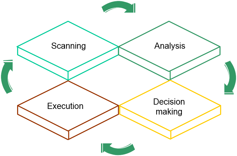
Operating mechanism
RRM operates as follows:
1. Scanning
APs scan channels regularly after coming online and report collected information to the fat AP at specific intervals. To avoid affecting wireless services, APs scan channels only when no service traffic is being transmitted.
2. Analyzing
The fat AP analyzes the received information, including channel quality, channel interference conditions, and adjacent AP distribution, and builds a model of the surrounding network with real-time awareness of network changes for decision making.
3. Decision making
Based on the analysis result, the fat AP uses intelligent algorithms to adjust and optimize radio resources, and automatically evaluates the impact of the adjustment on the network to ensure that the system is reliably adjusted to accommodate changes in the WLAN.
4. Execution
The fat AP sends the adjustment policy to the target AP, and the AP adjusts the channel, bandwidth, and transmit power as configured in the policy. You can view the history of AP radio adjustment on the fat AP.
The fat AP continuously monitors the network environment and records any wireless environment changes for the next round of adjustment.
Figure 1 RRM working mechanism
Dynamic frequency selection
Two adjacent radios on the same channel might cause signal collision, and other radio sources such as radar signals and microwave ovens might interfere with the operation of radios. With DFS, the AP selects an optimal channel for each radio in real time to avoid co-channel interference and interference from other radio sources.
The following factors will trigger DFS:
· Error code rate—Physical layer error code rate and CRC error rate. CRC error rate shows the proportion of packets with CRC errors among all 802.11 packets.
· Interference rate—Proportion of interference packets among all data packets. Interference packets are packets destined for other radios.
· Interference condition—DFS is triggered when both the channel usage threshold and interference ratio threshold are reached or exceeded, but the received service traffic fails to reach the service traffic threshold.
¡ Channel usage threshold—Proportion of channel resources used for packet transmitting and receiving.
¡ Interference ratio threshold—Proportion of channel resources used by interferences to the total used channel resources.
¡ Service traffic threshold—Proportion of received service traffic to the total received traffic.
· Retransmission count—Proportion of retransmitted packets to the total transmitted packets. An AP retransmits a packet if it fails to receive an ACK before the response timeout timer expires.
· Noise threshold—Noise detected by the AP in the current working channel.
The AP uses the following procedure to perform DFS for a radio:
1. Detects the current channel and selects an optimal channel when high CRC error ratio, severe interference, frequent retransmission, or high channel usage occurs.
2. Compares the quality between the current channel and the optimal channel. The radio does not use the optimal channel until the quality gap between the two channels exceeds the tolerance level.
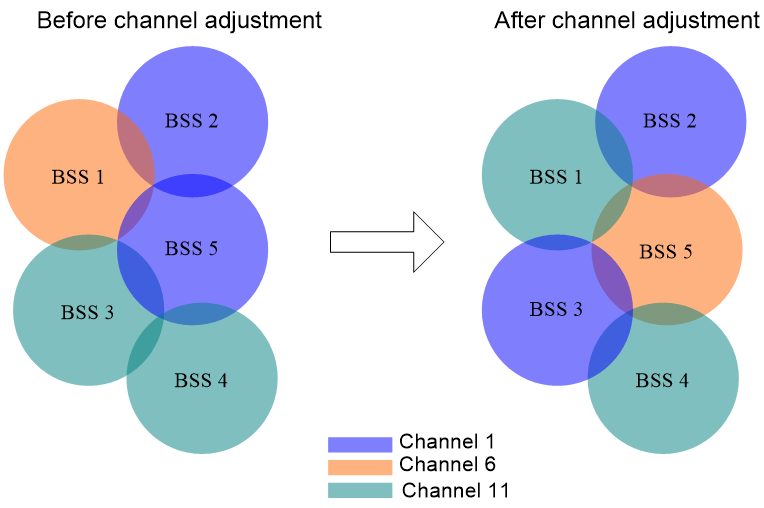
Figure 2 shows a DFS example. When the quality of the channels for BSS 1, BSS 3, and BSS 5 reaches a DFS threshold, the AP selects an optimal channel for each of them. This ensures wireless service quality.
Figure 2 Dynamic frequency selection
Transmit power control
TPC enables the AP to dynamically control access point transmit power based on real-time WLAN conditions. It can achieve desired RF coverage while avoiding channel interference between radios.
The AP maintains a neighbor report for each radio to record information about other radios detected by this radio.
The AP uses the following procedure to perform TPC for a radio:
1. Determines whether the number of manageable radios (all-channel radios or overlapping-channel radios) that can detect this radio has reached the adjacency factor.
If the number has not reached the adjacency factor, the radio uses the maximum transmit power.
If the number has reached the adjacency factor, the AP goes to step 2:
2. Ranks the radio's RSSIs detected by the AP's radios in descending order.
3. Compares the RSSI specified by the adjacency factor with the power adjustment threshold and takes one of the following actions:
¡ Decreases the radio's transmit power when the RSSI rises above the threshold.
¡ Increases the radio's transmit power when the RSSI drops below the threshold.
Radios that can participate in TPC calculation for a radio include the following types:
· All-channel radios—Include all manageable radios that detect the radio. TPC based on all-channel radios can better control the signal coverage.
· Overlapping-channel radios—Include manageable radios that detect the radio on a channel overlapping with the radio's transmit channel. TPC based on overlapping-channel radios can expand signal coverage without increasing interference.
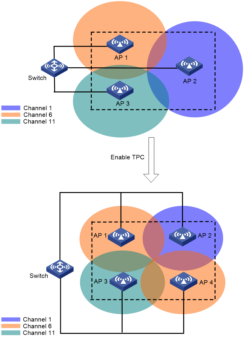
As shown in Figure 3, each AP has only one radio enabled. Before AP 4 joins, the number of manageable radios detected by each radio does not reach the adjacency factor 3. The radios use the maximum transmit power. After AP 4 joins, the number of manageable radios detected by each radio reaches the adjacency factor 3. The APs uses TPC to adjust the transmit powers for all radios.
Figure 3 Transmit power control
Bandwidth adjustment
802.11n and 802.11ac allow combination of adjacent channels to increase the data transmisstion rate. However, this practice can decrease data transmission stability, because signal interference is easy to occur.
Automatic bandwidth adjustment enables the AP to start channel quality detection when the automatic bandwidth adjustment interval is reached, and determines whether to perform bandwidth adjustment. It decreases the bandwidth for a radio to reduce interference if a large number of neighbor radios exist, and increase the bandwidth to increase the transmission rate if only few neighbor radios exist.
Auto bandwidth adjustment uses the following rules:
· Decreases radio bandwidth to reduce interference when APs are densely deployed.
· Increases radio bandwidth to increase the data transmission speed when APs are sparsely deployed.
· Reduces overlapping channels for adjacent APs as much as possible to minimize co-channel interference.
· Ensures that APs and clients can negotiate appropriate rates, ensuring the access rate of clients and increasing the capacity of the entire network.
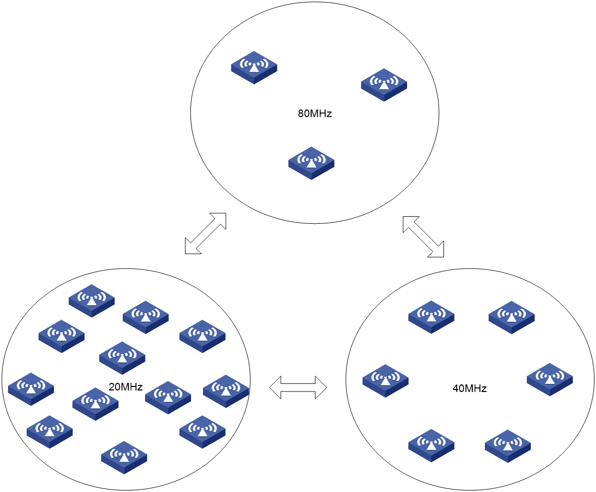
The fat AP evaluates the channel quality when each auto bandwidth adjustment period is reached and determines whether to adjust the bandwidth based on the evaluation result.
As shown in Figure 4, when the fat AP detects that too many neighbor APs and clients exist for an AP, it decreases the radio bandwidth to reduce interference. When the fat AP detects that only a few neighbor APs and clients exist for an AP, it increases the radio bandwidth to increase the transmission speed and network capacity.
Figure 4 Automatic bandwidth adjustment
WLAN RRM tasks at a glance
To configure RRM, perform the following tasks:
· Configuring automatic bandwidth adjustment
· Configuring a radio baseline
· Enabling SNMP notifications for WLAN RRM
Configuring DFS
About DFS
The AP supports the following DFS methods:
· Periodic auto-DFS—The AP automatically performs DFS for a radio at the channel calibration interval.
· On-demand DFS—The AP waits for a channel calibration interval and then performs DFS for all radios. You must perform this task every time you want the AP to perform DFS for radios.
Tasks at a glance
To configure DFS, perform the following tasks:
3. (Optional.) Setting the channel calibration interval for auto-DFS
4. (Optional.) Configuring DFS trigger parameters
5. (Optional.) Configuring radar detection-triggered RRM
Configuration prerequisites
For DFS to work, configure the AP to automatically select a channel for a radio by using the channel auto command. For more information about the channel auto command, see Radio Resources Management Command Reference.
Enabling auto-DFS
1. Enter system view.
system-view
2. Enter global configuration view.
wlan global-configuration
3. Enable auto-DFS.
calibrate-channel self-decisive enable { 2.4g | 5g | 6g | all }
By default, auto-DFS is disabled.
Configuring on-demand DFS
Performing on-demand DFS for all radios
|
|
CAUTION: On-demand DFS for all radios consumes a lot of system resources on the AP and might affect service operation. Please use this feature with caution. |
1. Enter system view.
system-view
2. Perform on-demand DFS for radios of all APs.
wlan calibrate-channel pronto ap all { 2.4g | 5g | 6g | all }
Performing on-demand DFS for the specified radio
1. Enter system view.
system-view
2. Perform on-demand DFS for the specified radio.
wlan rrm calibration-channel ap name ap-name [ radio radio-id ] [ force ]
The system will take a few minutes to scan channels and collect channel data. This might cause packet loss. During the calibration process, do not disable the radios or change channel scanning or WLAN RRM settings.
Setting the channel calibration interval for auto-DFS
1. Enter system view.
system-view
2. Set the channel calibration interval.
wlan rrm calibration-channel interval minutes
By default, the channel calibration interval is 31 minutes.
Configuring DFS trigger parameters
Restrictions and guidelines
As a best practice for accurate channel adjustment, configure the same DFS trigger parameters for all radios enabled with DFS.
Procedure
1. Enter system view.
system-view
2. Enter global configuration view.
wlan global-configuration
3. Set the CRC error threshold for 2.4 GHz, 5 GHz, and 6 GHz radios.
¡ For 2.4 GHz radios:
calibrate-channel 2.4g crc-error-threshold percent
By default, the CRC error threshold is 0 for 2.4 GHz radios.
¡ For 5 GHz radios:
calibrate-channel 5g crc-error-threshold percent
By default, the CRC error threshold is 0 for 5 GHz radios.
¡ For 6 GHz radios:
calibrate-channel 6g crc-error-threshold percent
By default, the CRC error threshold is 0 for 6 GHz radios.
4. Set the channel usage threshold for 2.4 GHz, 5 GHz, and 6 GHz radios.
¡ For 2.4 GHz radios:
calibrate-channel 2.4g channel-usage-threshold percent percent
By default, the channel usage threshold is 60 for 2.4 GHz radios.
¡ For 5 GHz radios:
calibrate-channel 5g channel-usage-threshold percent percent
By default, the channel usage threshold is 60 for 5 GHz radios.
¡ For 6 GHz radios:
calibrate-channel 6g channel-usage-threshold percent percent
By default, the channel usage threshold is 60 for 6 GHz radios.
5. Set the interference threshold for 2.4 GHz, 5 GHz, and 6 GHz radios.
¡ For 2.4 GHz radios:
calibrate-channel 2.4g interference-threshold percent percent
By default, the interference threshold is 70 for 2.4 GHz radios.
¡ For 5 GHz radios:
calibrate-channel 5g interference-threshold percent percent
By default, the interference threshold is 70 for 5 GHz radios.
¡ For 6 GHz radios:
calibrate-channel 6g interference-threshold percent percent
By default, the interference threshold is 70 for 6 GHz radios.
6. Set the received service traffic threshold for 2.4 GHz, 5 GHz, and 6 GHz radios.
¡ For 2.4 GHz radios:
calibrate-channel 2.4g receive-service-traffic threshold value
By default, the received service traffic threshold is 10 Mbps for 2.4 GHz radios.
¡ For 5 GHz radios:
calibrate-channel 5g receive-service-traffic threshold value
By default, the received service traffic threshold is 10 Mbps for 5 GHz radios.
¡ For 6 GHz radios:
calibrate-channel 6g receive-service-traffic threshold value
By default, the received service traffic threshold is 10 Mbps for 6 GHz radios.
7. Set the tolerance level for 2.4 GHz, 5 GHz, and 6 GHz radios.
¡ For 2.4 GHz radios:
calibrate-channel 2.4g tolerance-level percent
By default, the tolerance level is 1 for 2.4 GHz radios.
¡ For 5 GHz radios:
calibrate-channel 5g tolerance-level percent
By default, the tolerance level is 0 for 5 GHz radios.
¡ For 6 GHz radios:
calibrate-channel 6g tolerance-level percent
By default, the tolerance level is 0 for 6 GHz radios.
8. Set the noise threshold for 2.4 GHz, 5 GHz, and 6 GHz radios.
¡ For 2.4 GHz radios:
calibrate-channel 2.4g noise-threshold value
By default, the noise threshold is 0 for 2.4 GHz radios.
¡ For 5 GHz radios:
calibrate-channel 5g noise-threshold value
By default, the noise threshold is 0 for 5 GHz radios.
¡ For 6 GHz radios:
calibrate-channel 6g noise-threshold value
By default, the noise threshold is 0 for 6 GHz radios.
9. Set the retransmission threshold for 2.4 GHz, 5 GHz, and 6 GHz radios.
¡ For 2.4 GHz radios:
calibrate-channel 2.4g retransmission-threshold value
By default, the retransmission threshold is 0 for 2.4 GHz radios.
¡ For 5 GHz radios:
calibrate-channel 5g retransmission-threshold value
By default, the retransmission threshold is 0 for 5 GHz radios.
¡ For 6 GHz radios:
calibrate-channel 6g retransmission-threshold value
By default, the retransmission threshold is 0 for 6 GHz radios.
Configuring radar detection-triggered RRM
About this task
With radar detection enabled, if an AP detects a radar signal on the current channel, it either switch the channel or go silent to prevent radar interference. However, the new channel might lead to a degraded wireless network experience due to high interference or other issues. In such cases, you can enable radar detection-triggered RRM. After an AP detects radar signals and switches the channel, it notifies RRM to evaluate the new channel for further adjustments. If necessary, RRM automatically adjusts the channel to improve wireless network quality.
Procedures
1. Enter system view.
system-view
2. Enter global configuration view.
wlan global-configuration
3. Enable radar detection-triggered RRM.
calibrate-channel track radar-detect enable
By default, radar detection-triggered RRM is disabled.
Configuring TPC
About TPC
The AP supports the following TPC methods:
· Auto-TPC—The AP automatically performs TPC for a radio at the power calibration interval.
· On-demand TPC—The AP waits for a power calibration interval and then performs TPC for all radios. You must perform this task every time you want the AP to perform TPC for radios.
Tasks at a glance
To configure TPC, perform the following tasks:
3. (Optional.) Setting the power calibration interval for auto-TPC
4. (Optional.) Configuring TPC trigger parameters
5. (Optional.) Setting the power range
Configuration prerequisites
Make sure the power lock feature is disabled before configuring TPC. For more information about power lock, see "Configuring radio management."
Enabling auto-TPC
1. Enter system view.
system-view
2. Enter global configuration view.
wlan global-configuration
3. Enable auto-TPC.
calibrate-power self-decisive enable { 2.4g | 5g | 6g | all }
By default, auto-TPC is disabled.
You can enable auto-TPC for the 2.4GHz band, the 5GHz band, the 6GHz band, or all.
Performing on-demand TPC
Restrictions and guidelines
This feature consumes system resources. Use it with caution.
The AP waits for a power calibration interval after you enable on-demand TPC and then performs TPC.
Procedure
1. Enter system view.
system-view
2. Perform on-demand TPC for radios of the specified radios.
wlan calibrate-power pronto ap all { 2.4g | 5g | 6g | all }
Setting the power calibration interval for auto-TPC
1. Enter system view.
system-view
2. Set the power calibration interval for auto-TPC.
wlan rrm calibration-power interval minutes
By default, the power calibration interval is 11 minutes for auto-TPC.
Configuring TPC trigger parameters
Restrictions and guidelines
The adjacency factor and power adjustment threshold determine TPC for a radio. The adjacency factor defines the quantity of manageable detected radios that trigger TPC and the ranking of the RSSI used for comparison with the power adjustment threshold. Set an appropriate adjacency factor as needed.
As a best practice for accurate power adjustment, configure the same TPC trigger parameters for all radios enabled with TPC.
Procedure
1. Enter system view.
system-view
2. Enter global configuration view.
wlan global-configuration
3. Set the adjacency factor for 2.4 GHz, 5 GHz, and 6 GHz radios.
¡ For 2.4 GHz radios:
calibrate-power 2.4g adjacency-factor neighbor
By default, the adjacency factor is 1 for 2.4 GHz radios.
¡ For 5 GHz radios:
calibrate-power 5g adjacency-factor neighbor
By default, the adjacency factor is 1 for 5 GHz radios.
¡ For 6 GHz radios:
calibrate-power 6g adjacency-factor neighbor
By default, the adjacency factor is 1 for 6 GHz radios.
4. Set the power adjustment threshold for 2.4 GHz, 5 GHz, and 6 GHz radios..
¡ For 2.4 GHz radios:
calibrate-power 2.4g threshold value
By default, the power adjustment threshold is 65 for 2.4 GHz radios.
¡ For 5 GHz radios:
calibrate-power 5g threshold value
By default, the power adjustment threshold is 65 for 5 GHz radios.
¡ For 6 GHz radios:
calibrate-power 6g threshold value
By default, the power adjustment threshold is 65 for 6 GHz radios.
Setting the power range
About this task
To avoid the adjusted power being too low and affecting normal operations, you can set the minimum transmit power of a radio to ensure the adjusted power meets normal usage. The transmit power set by TPC will not exceed the maximum power configured by this function.
Procedure
1. Enter system view.
system-view
2. Enter global configuration view.
wlan global-configuration
3. Specify the power range.
calibrate-power { 2.4g | 5g | 6g } power-range min-power to max-power
By default, the minimum transmit power is 6 dBm for 2.4 GHz radios and 11 dBm for 5 GHz and 6 GHz radios. The maximum transmit power of a 2.4 GHz, 5 GHz, or 6 GHz radio is the maximum transmit power supported by the radio.
Configuring automatic bandwidth adjustment
Tasks at a glance
To configure auto bandwidth adjustment, perform the following tasks:
1. Enabling automatic bandwidth adjustment
2. (Optional.) Setting the interval for automatic bandwidth adjustment
Enabling automatic bandwidth adjustment
About this task
With automatic bandwidth adjustment enabled, the AP starts channel quality detection when the automatic bandwidth adjustment interval is reached, and determines whether to perform bandwidth adjustment. It decreases the bandwidth for a radio to reduce interference if a large number of neighbor radios exist, and increase the bandwidth to increase the transmission rate if only few neighbor radios exist.
Restrictions and guidelines
This feature takes effect only on 5 GHz and 6 GHz radios.
Procedure
1. Enter system view.
system-view
2. Enter global configuration view.
wlan global-configuration
3. Enable automatic bandwidth adjustment.
calibrate-bandwidth self-decisive enable { 5g | 6g | all }
By default, automatic bandwidth adjustment is disabled.
Setting the interval for automatic bandwidth adjustment
1. Enter system view.
system-view
2. Set the interval for automatic bandwidth adjustment.
wlan rrm calibration-bandwidth interval minutes
By default, the interval for automatic bandwidth adjustment is 29 minutes.
Configuring a radio baseline
About this task
A radio baseline saves the working channel, transmit rate, and other radio attributes for radios. You can create a radio baseline by saving the current radio settings and apply the baseline to use these settings as needed.
A radio baseline is saved in a .csv file in the file system.
A radio baseline cannot be applied to a radio when one of the following conditions is met:
· The radio is down.
· The radio mode in the baseline is different from the actual radio mode.
· The location identifier in the baseline is different from the actual location identifier.
· No service template is bound to the radio or the bound service template is disabled.
· The channel in the baseline is illegal.
· The bandwidth in the baseline is different from the actual bandwidth.
· The radio uses a manually specified channel.
· The working channel of the radio is locked.
· The channel or power holddown timer for the radio has not expired.
· The channel in the baseline does not match the specified channel gap.
· The transmit power of the radio is locked.
· The power holddown timer for the radio has not expired.
· The transmit power in the baseline is lower than the specified minimum transmit power for the radio.
· The transmit power in the baseline is higher than the specified maximum transmit power for the radio.
Procedure
1. Enter system view.
system-view
2. Create a radio baseline by saving the current radio settings.
wlan rrm baseline save name baseline-name global
3. Apply the baseline.
wlan rrm baseline apply name baseline-name
4. (Optional.) Delete a radio baseline.
wlan rrm baseline remove name baseline-name
Enabling SNMP notifications for WLAN RRM
About this task
To report critical WLAN RRM events to an NMS, enable SNMP notifications for WLAN RRM. For WLAN RRM event notifications to be sent correctly, you must also configure SNMP as described in Network Management and Monitoring Configuration Guide.
Procedure
1. Enter system view.
system-view
2. Enable SNMP notifications for WLAN RRM.
snmp-agent trap enable wlan rrm
By default, SNMP notifications are disabled for WLAN RRM.
Display and maintenance commands for WLAN RRM
Execute display commands in any view.
|
Task |
Command |
|
Display radio baseline information. |
display wlan rrm baseline { all | name baseline-name } [ verbose ] |
|
Display the history records of radio baseline application. |
display wlan rrm baseline apply-history [ verbose ] |
|
Display the RRM adjustment history. |
display wlan rrm-history ap { all | name ap-name } |
|
Display detailed WLAN RRM information. |
display wlan rrm-status ap { all | name ap-name } [ neighbor-type { managed | unmanaged } ] |
WLAN RRM configuration examples
Example: Configuring periodic auto-DFS
Network configuration
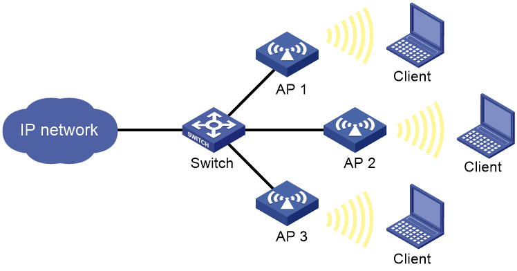
As shown in Figure 5, configure periodic auto-DFS to adjust channels for radios of the APs when a channel adjustment trigger condition is met.
Procedure
# Enable auto-DFS for AP 1.
<AP1> system-view
[AP1] wlan global-configuration
[AP1-wlan-global-configuration] calibrate-channel self-decisive enable all
# Configure DFS trigger parameters.
[AP1-wlan-global-configuration] calibrate-channel 2.4g crc-error-threshold 20
[AP1-wlan-global-configuration] calibrate-channel 5g crc-error-threshold 20
[AP1-wlan-global-configuration] calibrate-channel 2.4g channel-usage-threshold percent 70
[AP1-wlan-global-configuration] calibrate-channel 5g channel-usage-threshold percent 70
[AP1-wlan-global-configuration] calibrate-channel 2.4g interference-threshold percent 75
[AP1-wlan-global-configuration] calibrate-channel 5g interference-threshold percent 75
[AP1-wlan-global-configuration] calibrate-channel 2.4g tolerance-level 20
[AP1-wlan-global-configuration] calibrate-channel 5g tolerance-level 20
[AP1-wlan-global-configuration] quit
# Set the channel holddown time to 30 minutes.
[AP1] wlan rrm calibration-channel interval 30
# Configure auto-DFS for AP 2 and AP 3 in the same way auto-DFS is configured for AP 1. (Details not shown.)
Verifying the configuration
# Execute the display wlan rrm-status ap all command. Verify that the working channels for radios of the APs change when a channel adjustment trigger condition is met and the calibration interval is reached. (Details not shown.)
# Use the display wlan rrm-history ap all command to view the channel adjustment reason. (Details not shown.)