- Table of Contents
-
- 08-Radio Resources Management Configuration Guide
- 00-Preface
- 01-Radio management configuration
- 02-WLAN radio load balancing configuration
- 03-WLAN load balancing configuration
- 04-WLAN radio resource measurement configuration
- 05-Band navigation configuration
- 06-WLAN RRM configuration
- 07-Channel scanning configuration
- 08-Spectrum management configuration
- Related Documents
-
| Title | Size | Download |
|---|---|---|
| 01-Radio management configuration | 743.53 KB |
Restrictions: Hardware compatibility with radio management
Restrictions: Radio mode compatibility
Radio management tasks at a glance
Enabling or disabling a radio interface
Configuring basic radio functions
Setting the maximum transmit power
Setting the maximum number of clients that can associate with an AP
Setting the maximum transmission distance
Performing on-demand channel usage measurement
Configuring the A-MPDU aggregation method
Configuring the A-MSDU aggregation method
Configuring the client dot11n-only feature
Setting the 802.11n bandwidth mode
Configuring 802.11ac functions
Configuring the client dot11ac-only feature
Setting the 802.11ac bandwidth mode
Configuring 802.11ax functions
Configuring the client dot11ax-only feature
Setting the 802.11ax bandwidth mode
Setting the 802.11be bandwidth mode
Configuring preamble puncturing
Display and maintenance commands for radio management
Radio management configuration examples
Example: Configuring basic radio functions
Configuring radio management
About radio management
Radio frequency (RF) is a rate of electrical oscillation in the range of 300 KHz to 300 GHz. WLAN uses the 2.4 GHz band and 5 GHz band radio frequencies as the transmission media. The 2.4 GHz band includes radio frequencies from 2.4 GHz to 2.4835 GHz. The 5 GHz band includes radio frequencies from 5.150 GHz to 5.350 GHz and from 5.725 GHz to 5.850 GHz. The 6 GHz band includes radio frequencies from 5.925 GHz to 7.125 GHz.
The term "radio frequency" or its abbreviation RF is also used as a synonym for "radio" in wireless communication.
Radio mode
IEEE defines the 802.11a, 802.11b, 802.11g, 802.11n, 802.11ac, 802.11ax, and 802.11be radio modes. 802.11be operates on the 2.4 GHz, 5 GHz, and 6 GHz bands, with the mode operating on the 2.4 GHz band called 802.11gbe, mode operating on the 5 GHz band called 802.11abe, and the mode operating on the 6 GHz band called 802.11be.
H3C defines an 802.11gax radio mode that enables 802.11ax radios to use the 2.4 GHz band and defines an 802.11eax radio mode that enables 802.11ax radios to use the 6 GHz band.
|
|
NOTE: In this document, the term "802.11ax" refers to 802.11ax, 802.11gax, and 802.11eax, and the term "802.11be" refers to 802.11be, 802.11abe, and 802.11gbe, unless otherwise specified. |
Table 1 provides a comparison of these radio modes.
Table 1 Comparison of 802.11 standards
|
IEEE standard |
Frequency band |
Maximum rate |
|
802.11a |
5 GHz |
54 Mbps |
|
802.11b |
2.4 GHz |
11 Mbps |
|
802.11g |
2.4 GHz |
54 Mbps |
|
802.11n |
2.4 GHz or 5 GHz |
600 Mbps |
|
802.11ac |
5 GHz |
6900 Mbps |
|
802.11ax |
5 GHz |
9600 Mbps |
|
802.11gax |
2.4 GHz |
6900 Mbps |
|
802.11eax |
6 GHz |
9600 Mbps |
|
802.11be |
6 GHz |
46100 Mbps |
|
802.11abe |
5 GHz |
46100 Mbps |
|
802.11gbe |
2.4 GHz |
19200 Mbps |
Channel
A channel is a range of frequencies with a specific bandwidth.
The 2.4 GHz band has 14 channels. The bandwidth for each channel is 20 MHz and each two channels are spaced 5 MHz apart. Among the 14 channels, four groups of non-overlapping channels exist and the most commonly used one contains channels 1, 6, and 11.
The 5 GHz band can provide higher rates and is more immune to interference. There are 24 non-overlapping channels designated to the 5 GHz band. The channels are spaced 20 MHz apart with a bandwidth of 20 MHz. The available channels vary by country.
The 6 GHz band offers a total bandwidth of 1200 MHz, which can be divided into 59 channels with a width of 20 MHz, 29 channels with a width of 40 MHz, 14 channels with a width of 80 MHz, 7 channels with a width of 160 MHz, or 3 channels with a width of 320 MHz. This is twice as wide as the combined bandwidth of the previous 2.4 GHz and 5 GHz bands. The increased bandwidth provides three times more available frequency spectrum for Wi-Fi applications, alleviating the current shortage of Wi-Fi spectrum resources.
Transmit power
Transmit power reflects the signal strength of a wireless device. A higher transmit power enables a radio to cover a larger area but it brings more interference to adjacent devices. The signal strength decreases as the transmission distance increases.
Transmission rate
Transmission rate refers to the speed at which wireless devices transmit traffic. It varies by radio mode and spreading, coding, and modulation schemes. The following are rates supported by different types of radios:
· 802.11a—6 Mbps, 9 Mbps, 12 Mbps, 18 Mbps, 24 Mbps, 36 Mbps, 48 Mbps, and 54 Mbps.
· 802.11b—1 Mbps, 2 Mbps, 5.5 Mbps, and 11 Mbps.
· 802.11g—1 Mbps, 2 Mbps, 5.5 Mbps, 6 Mbps, 9 Mbps, 11 Mbps, 12 Mbps, 18 Mbps, 24 Mbps, 36 Mbps, 48 Mbps, and 54 Mbps.
· 802.11n—Rates for 802.11n radios vary by channel bandwidth and number of spatial streams. For more information, see "MCS."
· 802.11ac—Rates for 802.11ac radios vary by channel bandwidth and number of spatial streams (NSS). For more information, see "VHT-MCS."
· 802.11ax—Rates for 802.11ax radios vary by channel bandwidth and number of spatial streams (NSS). For more information, see "HE-MCS."
· 802.11be—Rates for 802.11be radios vary by channel bandwidth and number of spatial streams (NSS). For more information, see "EHT-MCS."
MCS
Modulation and Coding Scheme (MCS) defined in IEEE 802.11n-2009 determines the modulation, coding, and number of spatial streams.
MCS types
802.11n MCSs are classified into the following types:
· Mandatory MCSs—Mandatory MCSs for an AP. To associate with an 802.11n AP, a client must support the mandatory MCSs for the AP.
· Supported MCSs—MCSs supported by an AP besides the mandatory MCSs. If a client supports both mandatory and supported MCSs, the client can use a supported rate to communicate with the AP.
· Multicast MCS—MCS for the rate at which an AP transmits multicast frames.
MCS parameters
An MCS is identified by an MCS index, which is represented by an integer in the range of 0 to 76. An MCS index is the mapping from MCS to a data rate.
Table 2 through Table 9 show sample MCS parameters for 20 MHz and 40 MHz.
When the bandwidth mode is 20 MHz, MCS indexes 0 through 15 are mandatory for APs, and MCS indexes 0 through 7 are mandatory for clients.
Table 2 MCS parameters (20 MHz, NSS=1)
|
MCS index |
Number of spatial streams |
Modulation |
Data rate (Mbps) |
|
|
800ns GI |
400ns GI |
|||
|
0 |
1 |
BPSK |
6.5 |
7.2 |
|
1 |
1 |
QPSK |
13.0 |
14.4 |
|
2 |
1 |
QPSK |
19.5 |
21.7 |
|
3 |
1 |
16-QAM |
26.0 |
28.9 |
|
4 |
1 |
16-QAM |
39.0 |
43.3 |
|
5 |
1 |
64-QAM |
52.0 |
57.8 |
|
6 |
1 |
64-QAM |
58.5 |
65.0 |
|
7 |
1 |
64-QAM |
65.0 |
72.2 |
Table 3 MCS parameters (20 MHz, NSS=2)
|
MCS index |
Number of spatial streams |
Modulation |
Data rate (Mbps) |
|
|
800ns GI |
400ns GI |
|||
|
8 |
2 |
BPSK |
13.0 |
14.4 |
|
9 |
2 |
QPSK |
26.0 |
28.9 |
|
10 |
2 |
QPSK |
39.0 |
43.3 |
|
11 |
2 |
16-QAM |
52.0 |
57.8 |
|
12 |
2 |
16-QAM |
78.0 |
86.7 |
|
13 |
2 |
64-QAM |
104.0 |
115.6 |
|
14 |
2 |
64-QAM |
117.0 |
130.0 |
|
15 |
2 |
64-QAM |
130.0 |
144.4 |
Table 4 MCS parameters (20 MHz, NSS=3)
|
MCS index |
Number of spatial streams |
Modulation |
Data rate (Mbps) |
|
|
800ns GI |
400ns GI |
|||
|
16 |
3 |
BPSK |
19.5 |
21.7 |
|
17 |
3 |
QPSK |
39.0 |
43.3 |
|
18 |
3 |
QPSK |
58.5 |
65.0 |
|
19 |
3 |
16-QAM |
78.0 |
86.7 |
|
20 |
3 |
16-QAM |
117.0 |
130.0 |
|
21 |
3 |
64-QAM |
156.0 |
173.3 |
|
22 |
3 |
64-QAM |
175.5 |
195.0 |
|
23 |
3 |
64-QAM |
195.0 |
216.7 |
Table 5 MCS parameters (20 MHz, NSS=4)
|
MCS index |
Number of spatial streams |
Modulation |
Data rate (Mbps) |
|
|
800ns GI |
400ns GI |
|||
|
24 |
4 |
BPSK |
26.0 |
28.9 |
|
25 |
4 |
QPSK |
52.0 |
57.8 |
|
26 |
4 |
QPSK |
78.0 |
86.7 |
|
27 |
4 |
16-QAM |
104.0 |
115.6 |
|
28 |
4 |
16-QAM |
156.0 |
173.3 |
|
29 |
4 |
64-QAM |
208.0 |
231.1 |
|
30 |
4 |
64-QAM |
234.0 |
260.0 |
|
31 |
4 |
64-QAM |
260.0 |
288.9 |
Table 6 MCS parameters (40 MHz, NSS=1)
|
MCS index |
Number of spatial streams |
Modulation |
Data rate (Mbps) |
|
|
800ns GI |
400ns GI |
|||
|
0 |
1 |
BPSK |
13.5 |
15.0 |
|
1 |
1 |
QPSK |
27.0 |
30.0 |
|
2 |
1 |
QPSK |
40.5 |
45.0 |
|
3 |
1 |
16-QAM |
54.0 |
60.0 |
|
4 |
1 |
16-QAM |
81.0 |
90.0 |
|
5 |
1 |
64-QAM |
108.0 |
120.0 |
|
6 |
1 |
64-QAM |
121.5 |
135.0 |
|
7 |
1 |
64-QAM |
135.0 |
150.0 |
Table 7 MCS parameters (40 MHz, NSS=2)
|
MCS index |
Number of spatial streams |
Modulation |
Data rate (Mbps) |
|
|
800ns GI |
400ns GI |
|||
|
8 |
2 |
BPSK |
27.0 |
30.0 |
|
9 |
2 |
QPSK |
54.0 |
60.0 |
|
10 |
2 |
QPSK |
81.0 |
90.0 |
|
11 |
2 |
16-QAM |
108.0 |
120.0 |
|
12 |
2 |
16-QAM |
162.0 |
180.0 |
|
13 |
2 |
64-QAM |
216.0 |
240.0 |
|
14 |
2 |
64-QAM |
243.0 |
270.0 |
|
15 |
2 |
64-QAM |
270.0 |
300.0 |
Table 8 MCS parameters (40 MHz, NSS=3)
|
MCS index |
Number of spatial streams |
Modulation |
Data rate (Mbps) |
|
|
800ns GI |
400ns GI |
|||
|
16 |
3 |
BPSK |
40.5 |
45.0 |
|
17 |
3 |
QPSK |
81.0 |
90.0 |
|
18 |
3 |
QPSK |
121.5 |
135.0 |
|
19 |
3 |
16-QAM |
162.0 |
180.0 |
|
20 |
3 |
16-QAM |
243.0 |
270.0 |
|
21 |
3 |
64-QAM |
324.0 |
360.0 |
|
22 |
3 |
64-QAM |
364.5 |
405.0 |
|
23 |
3 |
64-QAM |
405.0 |
450.0 |
Table 9 MCS parameters (40 MHz, NSS=4)
|
MCS index |
Number of spatial streams |
Modulation |
Data rate (Mbps) |
|
|
800ns GI |
400ns GI |
|||
|
24 |
4 |
BPSK |
54.0 |
60.0 |
|
25 |
4 |
QPSK |
108.0 |
120.0 |
|
26 |
4 |
QPSK |
162.0 |
180.0 |
|
27 |
4 |
16-QAM |
216.0 |
240.0 |
|
28 |
4 |
16-QAM |
324.0 |
360.0 |
|
29 |
4 |
64-QAM |
432.0 |
480.0 |
|
30 |
4 |
64-QAM |
486.0 |
540.0 |
|
31 |
4 |
64-QAM |
540.0 |
600.0 |
|
|
NOTE: · For all the MCS data rate tables, see IEEE 802.11n-2009. · Support for MCS indexes depends on the device model. |
VHT-MCS
Very High Throughput Modulation and Coding Scheme (VHT-MCS) defined in IEEE 802.11ac determines the wireless data rates.
VHT-MCS types
802.11ac VHT-MCSs are classified into the following types:
· Mandatory VHT-MCSs—Mandatory VHT-MCSs for an AP. To associate with an 802.11ac AP, a client must support the mandatory VHT-MCSs for the AP.
· Supported VHT-MCSs—VHT-MCSs supported by an AP besides the mandatory VHT-MCSs. If a client supports both mandatory and supported VHT-MCSs, the client can use a supported rate to communicate with the AP.
· Multicast VHT-MCS—VHT-MCS for the rate at which an AP transmits multicast frames.
VHT-MCS parameters
A VHT-MCS is identified by a VHT-MCS index, which is represented by an integer in the range of 0 to 9. A VHT-MCS index is the mapping from VHT-MCS to a data rate.
802.11ac supports the 20 MHz, 40 MHz, 80 MHz, and 160 MHz bandwidth modes, and supports a maximum of eight spatial streams.
Table 10 through Table 21 show VHT-MCS parameters that are supported by an AP.
Table 10 VHT-MCS parameters (20 MHz, NSS=1)
|
VHT-MCS index |
Modulation |
Data rate (Mbps) |
|
|
800ns GI |
400ns GI |
||
|
0 |
BPSK |
6.5 |
7.2 |
|
1 |
QPSK |
13.0 |
14.4 |
|
2 |
QPSK |
19.5 |
21.7 |
|
3 |
16-QAM |
26.0 |
28.9 |
|
4 |
16-QAM |
39.0 |
43.3 |
|
5 |
64-QAM |
52.0 |
57.8 |
|
6 |
64-QAM |
58.5 |
65.0 |
|
7 |
64-QAM |
65.0 |
72.2 |
|
8 |
256-QAM |
78.0 |
86.7 |
|
9 |
Not valid |
||
Table 11 VHT-MCS parameters (20 MHz, NSS=2)
|
VHT-MCS index |
Modulation |
Data rate (Mbps) |
|
|
800ns GI |
400ns GI |
||
|
0 |
BPSK |
13.0 |
14.4 |
|
1 |
QPSK |
26.0 |
28.9 |
|
2 |
QPSK |
39.0 |
43.3 |
|
3 |
16-QAM |
52.0 |
57.8 |
|
4 |
16-QAM |
78.0 |
86.7 |
|
5 |
64-QAM |
104.0 |
115.6 |
|
6 |
64-QAM |
117.0 |
130.0 |
|
7 |
64-QAM |
130.0 |
144.4 |
|
8 |
256-QAM |
156.0 |
173.3 |
|
9 |
Not valid |
||
Table 12 VHT-MCS parameters (20 MHz, NSS=3)
|
VHT-MCS index |
Modulation |
Data rate (Mbps) |
|
|
800ns GI |
400ns GI |
||
|
0 |
BPSK |
19.5 |
21.7 |
|
1 |
QPSK |
39.0 |
43.3 |
|
2 |
QPSK |
58.5 |
65.0 |
|
3 |
16-QAM |
78.0 |
86.7 |
|
4 |
16-QAM |
117.0 |
130.0 |
|
5 |
64-QAM |
156.0 |
173.3 |
|
6 |
64-QAM |
175.5 |
195.0 |
|
7 |
64-QAM |
195.0 |
216.7 |
|
8 |
256-QAM |
234.0 |
260.0 |
|
9 |
256-QAM |
260.0 |
288.9 |
Table 13 VHT-MCS parameters (20 MHz, NSS=4)
|
VHT-MCS index |
Modulation |
Data rate (Mbps) |
|
|
800ns GI |
400ns GI |
||
|
0 |
BPSK |
26.0 |
28.9 |
|
1 |
QPSK |
52.0 |
57.8 |
|
2 |
QPSK |
78.0 |
86.7 |
|
3 |
16-QAM |
104.0 |
115.6 |
|
4 |
16-QAM |
156.0 |
173.3 |
|
5 |
64-QAM |
208.0 |
231.1 |
|
6 |
64-QAM |
234.0 |
260.0 |
|
7 |
64-QAM |
260.0 |
288.9 |
|
8 |
256-QAM |
312.0 |
346.7 |
|
9 |
Not valid |
||
Table 14 VHT-MCS parameters (40 MHz, NSS=1)
|
VHT-MCS index |
Modulation |
Data rate (Mbps) |
|
|
800ns GI |
400ns GI |
||
|
0 |
BPSK |
13.5 |
15.0 |
|
1 |
QPSK |
27.0 |
30.0 |
|
2 |
QPSK |
40.5 |
45.0 |
|
3 |
16-QAM |
54.0 |
60.0 |
|
4 |
16-QAM |
81.0 |
90.0 |
|
5 |
64-QAM |
108.0 |
120.0 |
|
6 |
64-QAM |
121.5 |
135.0 |
|
7 |
64-QAM |
135.0 |
150.0 |
|
8 |
256-QAM |
162.0 |
180.0 |
|
9 |
256-QAM |
180.0 |
200.0 |
Table 15 VHT-MCS parameters (40 MHz, NSS=2)
|
VHT-MCS index |
Modulation |
Data rate (Mbps) |
|
|
800ns GI |
400ns GI |
||
|
0 |
BPSK |
27.0 |
30.0 |
|
1 |
QPSK |
54.0 |
60.0 |
|
2 |
QPSK |
81.0 |
90.0 |
|
3 |
16-QAM |
108.0 |
120.0 |
|
4 |
16-QAM |
162.0 |
180.0 |
|
5 |
64-QAM |
216.0 |
240.0 |
|
6 |
64-QAM |
243.0 |
270.0 |
|
7 |
64-QAM |
270.0 |
300.0 |
|
8 |
256-QAM |
324.0 |
360.0 |
|
9 |
256-QAM |
360.0 |
400.0 |
Table 16 VHT-MCS parameters (40 MHz, NSS=3)
|
VHT-MCS index |
Modulation |
Data rate (Mbps) |
|
|
800ns GI |
400ns GI |
||
|
0 |
BPSK |
40.5 |
45.0 |
|
1 |
QPSK |
81.0 |
90.0 |
|
2 |
QPSK |
121.5 |
135.0 |
|
3 |
16-QAM |
162.0 |
180.0 |
|
4 |
16-QAM |
243.0 |
270.0 |
|
5 |
64-QAM |
324.0 |
360.0 |
|
6 |
64-QAM |
364.5 |
405.0 |
|
7 |
64-QAM |
405.0 |
450.0 |
|
8 |
256-QAM |
486.0 |
540.0 |
|
9 |
256-QAM |
540.0 |
600.0 |
Table 17 VHT-MCS parameters(40 MHz, NSS=4)
|
VHT-MCS index |
Modulation |
Data rate (Mbps) |
|
|
800ns GI |
400ns GI |
||
|
0 |
BPSK |
54.0 |
60.0 |
|
1 |
QPSK |
108.0 |
120.0 |
|
2 |
QPSK |
162.0 |
180.0 |
|
3 |
16-QAM |
216.0 |
240.0 |
|
4 |
16-QAM |
324.0 |
360.0 |
|
5 |
64-QAM |
432.0 |
480.0 |
|
6 |
64-QAM |
486.0 |
540.0 |
|
7 |
64-QAM |
540.0 |
600.0 |
|
8 |
256-QAM |
648.0 |
720.0 |
|
9 |
256-QAM |
720.0 |
800.0 |
Table 18 VHT-MCS parameters (80 MHz, NSS=1)
|
VHT-MCS index |
Modulation |
Data rate (Mbps) |
|
|
800ns GI |
400ns GI |
||
|
0 |
BPSK |
29.3 |
32.5 |
|
1 |
QPSK |
58.5 |
65.0 |
|
2 |
QPSK |
87.8 |
97.5 |
|
3 |
16-QAM |
117.0 |
130.0 |
|
4 |
16-QAM |
175.5 |
195.0 |
|
5 |
64-QAM |
234.0 |
260.0 |
|
6 |
64-QAM |
263.0 |
292.5 |
|
7 |
64-QAM |
292.5 |
325.0 |
|
8 |
256-QAM |
351.0 |
390.0 |
|
9 |
256-QAM |
390.0 |
433.3 |
Table 19 VHT-MCS parameters (80 MHz, NSS=2)
|
VHT-MCS index |
Modulation |
Data rate (Mbps) |
|
|
800ns GI |
400ns GI |
||
|
0 |
BPSK |
58.5 |
65.0 |
|
1 |
QPSK |
117.0 |
130.0 |
|
2 |
QPSK |
175.5 |
195.0 |
|
3 |
16-QAM |
234.0 |
260.0 |
|
4 |
16-QAM |
351.0 |
390.0 |
|
5 |
64-QAM |
468.0 |
520.0 |
|
6 |
64-QAM |
526.5 |
585.0 |
|
7 |
64-QAM |
585.0 |
650.0 |
|
8 |
256-QAM |
702.0 |
780.0 |
|
9 |
256-QAM |
780.0 |
866.7 |
Table 20 VHT-MCS parameters (80 MHz, NSS=3)
|
VHT-MCS index |
Modulation |
Data rate (Mbps) |
|
|
800ns GI |
400ns GI |
||
|
0 |
BPSK |
87.8 |
97.5 |
|
1 |
QPSK |
175.5 |
195.0 |
|
2 |
QPSK |
263.3 |
292.5 |
|
3 |
16-QAM |
351.0 |
390.0 |
|
4 |
16-QAM |
526.5 |
585.0 |
|
5 |
64-QAM |
702.0 |
780.0 |
|
6 |
Not valid |
||
|
7 |
64-QAM |
877.5 |
975.0 |
|
8 |
256-QAM |
1053.0 |
1170.0 |
|
9 |
256-QAM |
1170.0 |
1300.0 |
Table 21 VHT-MCS parameters (80 MHz, NSS=4)
|
VHT-MCS index |
Modulation |
Data rate (Mbps) |
|
|
800ns GI |
400ns GI |
||
|
0 |
BPSK |
117.0 |
130.0 |
|
1 |
QPSK |
234.0 |
260.0 |
|
2 |
QPSK |
351.0 |
390.0 |
|
3 |
16-QAM |
468.0 |
520.0 |
|
4 |
16-QAM |
702.0 |
780.0 |
|
5 |
64-QAM |
936.0 |
1040.0 |
|
6 |
64-QAM |
1053.0 |
1170.0 |
|
7 |
64-QAM |
1170.0 |
1300.0 |
|
8 |
256-QAM |
1404.0 |
1560.0 |
|
9 |
256-QAM |
1560.0 |
1733.3 |
|
|
NOTE: · For all the VHT-MCS data rate tables, see IEEE 802.11ac-2013. · Support for VHT-MCS indexes depends on the AP model. · 802.11gac supports only the 20 MHz and 40 MHz bandwidth, with the corresponding VHT-MCS tables in Table 10 through Table 17. |
HE-MCS
High Efficiency Modulation and Coding Scheme (HE-MCS) defined in IEEE 802.11ax determines the wireless data rates.
HE-MCS types
802.11ax HE-MCSs are classified into the following types:
· Mandatory HE-MCSs—Mandatory HE-MCSs for an AP. To associate with an 802.11ax AP, a client must support the mandatory HE-MCSs for the AP.
· Supported HE-MCSs—HE-MCSs supported by an AP besides the mandatory HE-MCSs. If a client supports both mandatory and supported HE-MCSs, the client can use a supported rate to communicate with the AP.
· Multicast HE-MCS—HE-MCS for the rate at which an AP transmits multicast frames.
HE-MCS parameters
An HE-MCS is identified by an HE-MCS index, which is represented by an integer in the range of 0 to 11. An HE-MCS index is the mapping from HE-MCS to a data rate.
802.11ax supports the 20 MHz, 40 MHz, 80 MHz, and 160 MHz (80+80 MHz) bandwidth modes, and supports a maximum of eight spatial streams. 802.11gax supports the 20 MHz and 40 MHz bandwidth modes.
Table 22 through Table 33 show HE-MCS parameters that are supported by an AP.
Table 22 HE-MCS parameters (20 MHz, NSS=1)
|
HE-MCS index |
Spatial streams |
Modulation |
Data rate (Mbps) |
|
|
1600ns GI |
800ns GI |
|||
|
0 |
1 |
BPSK |
8 |
8.6 |
|
1 |
1 |
QPSK |
16 |
17.2 |
|
2 |
1 |
QPSK |
24 |
25.8 |
|
3 |
1 |
16-QAM |
33 |
34.4 |
|
4 |
1 |
16-QAM |
49 |
51.6 |
|
5 |
1 |
64-QAM |
65 |
68.8 |
|
6 |
1 |
64-QAM |
73 |
77.4 |
|
7 |
1 |
64-QAM |
81 |
86 |
|
8 |
1 |
256-QAM |
98 |
103.2 |
|
9 |
1 |
256-QAM |
108 |
114.7 |
|
10 |
1 |
1024-QAM |
122 |
129 |
|
11 |
1 |
1024-QAM |
135 |
143.4 |
Table 23 HE-MCS parameters (20 MHz, NSS=2)
|
HE-MCS index |
Spatial streams |
Modulation |
Data rate (Mbps) |
|
|
1600ns GI |
800ns GI |
|||
|
0 |
2 |
BPSK |
16 |
17.2 |
|
1 |
2 |
QPSK |
32 |
34.4 |
|
2 |
2 |
QPSK |
48 |
51.6 |
|
3 |
2 |
16-QAM |
66 |
68.8 |
|
4 |
2 |
16-QAM |
98 |
103.2 |
|
5 |
2 |
64-QAM |
130 |
137.6 |
|
6 |
2 |
64-QAM |
146 |
154.8 |
|
7 |
2 |
64-QAM |
162 |
172 |
|
8 |
2 |
256-QAM |
196 |
206.4 |
|
9 |
2 |
256-QAM |
216 |
229.4 |
|
10 |
2 |
1024-QAM |
244 |
258 |
|
11 |
2 |
1024-QAM |
270 |
286.8 |
Table 24 HE-MCS parameters (20 MHz, NSS=3)
|
HE-MCS index |
Spatial streams |
Modulation |
Data rate (Mbps) |
|
|
1600ns GI |
800ns GI |
|||
|
0 |
3 |
BPSK |
24 |
25.8 |
|
1 |
3 |
QPSK |
48 |
51.6 |
|
2 |
3 |
QPSK |
72 |
77.4 |
|
3 |
3 |
16-QAM |
99 |
103.2 |
|
4 |
3 |
16-QAM |
147 |
154.8 |
|
5 |
3 |
64-QAM |
195 |
206.4 |
|
6 |
3 |
64-QAM |
219 |
232.2 |
|
7 |
3 |
64-QAM |
243 |
258 |
|
8 |
3 |
256-QAM |
294 |
309.6 |
|
9 |
3 |
256-QAM |
324 |
344.1 |
|
10 |
3 |
1024-QAM |
366 |
387 |
|
11 |
3 |
1024-QAM |
405 |
430.2 |
Table 25 HE-MCS parameters (20 MHz, NSS=4)
|
HE-MCS index |
Spatial streams |
Modulation |
Data rate (Mbps) |
|
|
1600ns GI |
800ns GI |
|||
|
0 |
4 |
BPSK |
32 |
34.4 |
|
1 |
4 |
QPSK |
64 |
68.8 |
|
2 |
4 |
QPSK |
96 |
103.2 |
|
3 |
4 |
16-QAM |
132 |
137.6 |
|
4 |
4 |
16-QAM |
196 |
206.4 |
|
5 |
4 |
64-QAM |
260 |
275.2 |
|
6 |
4 |
64-QAM |
292 |
309.6 |
|
7 |
4 |
64-QAM |
324 |
344 |
|
8 |
4 |
256-QAM |
392 |
412.8 |
|
9 |
4 |
256-QAM |
432 |
458.8 |
|
10 |
4 |
1024-QAM |
488 |
516 |
|
11 |
4 |
1024-QAM |
540 |
573.6 |
Table 26 HE-MCS parameters (40 MHz, NSS=1)
|
HE-MCS index |
Spatial streams |
Modulation |
Data rate (Mbps) |
|
|
1600ns GI |
800ns GI |
|||
|
0 |
1 |
BPSK |
16 |
17.2 |
|
1 |
1 |
QPSK |
33 |
34.4 |
|
2 |
1 |
QPSK |
49 |
51.6 |
|
3 |
1 |
16-QAM |
65 |
68.8 |
|
4 |
1 |
16-QAM |
98 |
103.2 |
|
5 |
1 |
64-QAM |
130 |
137.6 |
|
6 |
1 |
64-QAM |
146 |
154.9 |
|
7 |
1 |
64-QAM |
163 |
172.1 |
|
8 |
1 |
256-QAM |
195 |
206.5 |
|
9 |
1 |
256-QAM |
217 |
229.4 |
|
10 |
1 |
1024-QAM |
244 |
258.1 |
|
11 |
1 |
1024-QAM |
271 |
286.8 |
Table 27 HE-MCS parameters (40 MHz, NSS=2)
|
HE-MCS index |
Spatial streams |
Modulation |
Data rate (Mbps) |
|
|
1600ns GI |
800ns GI |
|||
|
0 |
2 |
BPSK |
32 |
34.4 |
|
1 |
2 |
QPSK |
66 |
68.8 |
|
2 |
2 |
QPSK |
98 |
103.2 |
|
3 |
2 |
16-QAM |
130 |
137.6 |
|
4 |
2 |
16-QAM |
196 |
206.4 |
|
5 |
2 |
64-QAM |
260 |
275.2 |
|
6 |
2 |
64-QAM |
292 |
309.8 |
|
7 |
2 |
64-QAM |
326 |
344.2 |
|
8 |
2 |
256-QAM |
390 |
413 |
|
9 |
2 |
256-QAM |
434 |
458.8 |
|
10 |
2 |
1024-QAM |
488 |
516.2 |
|
11 |
2 |
1024-QAM |
542 |
573.6 |
Table 28 HE-MCS parameters (40 MHz, NSS=3)
|
HE-MCS index |
Spatial streams |
Modulation |
Data rate (Mbps) |
|
|
1600ns GI |
800ns GI |
|||
|
0 |
3 |
BPSK |
48 |
51.6 |
|
1 |
3 |
QPSK |
99 |
103.2 |
|
2 |
3 |
QPSK |
147 |
154.8 |
|
3 |
3 |
16-QAM |
195 |
206.4 |
|
4 |
3 |
16-QAM |
294 |
309.6 |
|
5 |
3 |
64-QAM |
390 |
412.8 |
|
6 |
3 |
64-QAM |
438 |
464.7 |
|
7 |
3 |
64-QAM |
489 |
516.3 |
|
8 |
3 |
256-QAM |
585 |
619.5 |
|
9 |
3 |
256-QAM |
651 |
688.2 |
|
10 |
3 |
1024-QAM |
732 |
774.3 |
|
11 |
3 |
1024-QAM |
813 |
860.4 |
Table 29 HE-MCS parameters(40 MHz, NSS=4)
|
HE-MCS index |
Spatial streams |
Modulation |
Data rate (Mbps) |
|
|
1600ns GI |
800ns GI |
|||
|
0 |
4 |
BPSK |
64 |
68.8 |
|
1 |
4 |
QPSK |
132 |
137.6 |
|
2 |
4 |
QPSK |
196 |
206.4 |
|
3 |
4 |
16-QAM |
260 |
275.2 |
|
4 |
4 |
16-QAM |
392 |
412.8 |
|
5 |
4 |
64-QAM |
520 |
550.4 |
|
6 |
4 |
64-QAM |
584 |
619.6 |
|
7 |
4 |
64-QAM |
652 |
688.4 |
|
8 |
4 |
256-QAM |
780 |
826 |
|
9 |
4 |
256-QAM |
868 |
917.6 |
|
10 |
4 |
1024-QAM |
976 |
1032.4 |
|
11 |
4 |
1024-QAM |
1084 |
1147.2 |
Table 30 HE-MCS parameters (80 MHz, NSS=1)
|
HE-MCS index |
Spatial streams |
Modulation |
Data rate (Mbps) |
|
|
1600ns GI |
800ns GI |
|||
|
0 |
1 |
BPSK |
34 |
36 |
|
1 |
1 |
QPSK |
68 |
72.1 |
|
2 |
1 |
QPSK |
102 |
108.1 |
|
3 |
1 |
16-QAM |
136 |
144.1 |
|
4 |
1 |
16-QAM |
204 |
216.2 |
|
5 |
1 |
64-QAM |
272 |
288.2 |
|
6 |
1 |
64-QAM |
306 |
324.4 |
|
7 |
1 |
64-QAM |
340 |
360.3 |
|
8 |
1 |
256-QAM |
408 |
432.4 |
|
9 |
1 |
256-QAM |
453 |
480.4 |
|
10 |
1 |
1024-QAM |
510 |
540.4 |
|
11 |
1 |
1024-QAM |
567 |
600.5 |
Table 31 HE-MCS parameters (80 MHz, NSS=2)
|
HE-MCS index |
Spatial streams |
Modulation |
Data rate (Mb/s) |
|
|
1600ns GI |
800ns GI |
|||
|
0 |
2 |
BPSK |
68 |
72 |
|
1 |
2 |
QPSK |
136 |
144.2 |
|
2 |
2 |
QPSK |
204 |
216.2 |
|
3 |
2 |
16-QAM |
272 |
288.2 |
|
4 |
2 |
16-QAM |
408 |
432.4 |
|
5 |
2 |
64-QAM |
544 |
576.4 |
|
6 |
2 |
64-QAM |
612 |
648.8 |
|
7 |
2 |
64-QAM |
680 |
720.6 |
|
8 |
2 |
256-QAM |
816 |
864.8 |
|
9 |
2 |
256-QAM |
906 |
960.8 |
|
10 |
2 |
1024-QAM |
1020 |
1080.8 |
|
11 |
2 |
1024-QAM |
1134 |
1201 |
Table 32 HE-MCS parameters (80 MHz, NSS=3)
|
HE-MCS index |
Spatial streams |
Modulation |
Data rate (Mbps) |
|
|
1600ns GI |
800ns GI |
|||
|
0 |
3 |
BPSK |
102 |
108 |
|
1 |
3 |
QPSK |
204 |
216.3 |
|
2 |
3 |
QPSK |
306 |
324.3 |
|
3 |
3 |
16-QAM |
408 |
432.3 |
|
4 |
3 |
16-QAM |
612 |
648.6 |
|
5 |
3 |
64-QAM |
816 |
864.6 |
|
6 |
3 |
64-QAM |
918 |
973.2 |
|
7 |
3 |
64-QAM |
1020 |
1080.9 |
|
8 |
3 |
256-QAM |
1224 |
1297.2 |
|
9 |
3 |
256-QAM |
1359 |
1441.2 |
|
10 |
3 |
1024-QAM |
1530 |
1621.2 |
|
11 |
3 |
1024-QAM |
1701 |
1801.5 |
Table 33 HE-MCS parameters (80 MHz, NSS=4)
|
HE-MCS index |
Spatial streams |
Modulation |
Data rate (Mbps) |
|
|
1600ns GI |
800ns GI |
|||
|
0 |
4 |
BPSK |
136 |
144 |
|
1 |
4 |
QPSK |
272 |
288.4 |
|
2 |
4 |
QPSK |
408 |
432.4 |
|
3 |
4 |
16-QAM |
544 |
576.4 |
|
4 |
4 |
16-QAM |
816 |
864.8 |
|
5 |
4 |
64-QAM |
1088 |
1152.8 |
|
6 |
4 |
64-QAM |
1224 |
1297.6 |
|
7 |
4 |
64-QAM |
1360 |
1441.2 |
|
8 |
4 |
256-QAM |
1632 |
1729.6 |
|
9 |
4 |
256-QAM |
1812 |
1921.6 |
|
10 |
4 |
1024-QAM |
2040 |
2161.6 |
|
11 |
4 |
1024-QAM |
2268 |
2402 |
Table 34 HE-MCS parameters (160 MHz/80 MHz+80 MHz, NSS=1)
|
HE-MCS index |
Spatial streams |
Modulation |
Data rate (Mbps) |
|
|
1600ns GI |
800ns GI |
|||
|
0 |
1 |
BPSK |
68 |
72.1 |
|
1 |
1 |
QPSK |
136 |
144.1 |
|
2 |
1 |
QPSK |
204 |
216.2 |
|
3 |
1 |
16-QAM |
272 |
288.2 |
|
4 |
1 |
16-QAM |
408 |
432.4 |
|
5 |
1 |
64-QAM |
544 |
576.5 |
|
6 |
1 |
64-QAM |
612 |
648.5 |
|
7 |
1 |
64-QAM |
681 |
720.6 |
|
8 |
1 |
256-QAM |
817 |
864.7 |
|
9 |
1 |
256-QAM |
907 |
960.7 |
|
10 |
1 |
1024-QAM |
1021 |
1080.9 |
|
11 |
1 |
1024-QAM |
1134 |
1201 |
Table 35 HE-MCS parameters (160 MHz/80 MHz+80 MHz, NSS=2)
|
HE-MCS index |
Spatial streams |
Modulation |
Data rate (Mbps) |
|
|
1600ns GI |
800ns GI |
|||
|
0 |
2 |
BPSK |
136 |
144.1 |
|
1 |
2 |
QPSK |
272 |
288.2 |
|
2 |
2 |
QPSK |
408 |
432.4 |
|
3 |
2 |
16-QAM |
544 |
576.5 |
|
4 |
2 |
16-QAM |
817 |
864.7 |
|
5 |
2 |
64-QAM |
1089 |
1152.9 |
|
6 |
2 |
64-QAM |
1225 |
1297.1 |
|
7 |
2 |
64-QAM |
1361 |
1441.2 |
|
8 |
2 |
256-QAM |
1633 |
1729.4 |
|
9 |
2 |
256-QAM |
1815 |
1921.5 |
|
10 |
2 |
1024-QAM |
2042 |
2161.8 |
|
11 |
2 |
1024-QAM |
2269 |
2401.9 |
Table 36 HE-MCS parameters (160 MHz/80 MHz+80 MHz, NSS=3)
|
HE-MCS index |
Spatial streams |
Modulation |
Data rate (Mbps) |
|
|
1600ns GI |
800ns GI |
|||
|
0 |
3 |
BPSK |
204 |
216.2 |
|
1 |
3 |
QPSK |
408 |
432.4 |
|
2 |
3 |
QPSK |
613 |
648.5 |
|
3 |
3 |
16-QAM |
817 |
864.7 |
|
4 |
3 |
16-QAM |
1225 |
1297.1 |
|
5 |
3 |
64-QAM |
1633 |
1729.4 |
|
6 |
3 |
64-QAM |
1838 |
1945.6 |
|
7 |
3 |
64-QAM |
2042 |
2161.8 |
|
8 |
3 |
256-QAM |
2450 |
2594.1 |
|
9 |
3 |
256-QAM |
2722 |
2882.4 |
|
10 |
3 |
1024-QAM |
3062 |
3242.6 |
|
11 |
3 |
1024-QAM |
3403 |
3602.9 |
Table 37 HE-MCS parameters (160 MHz/80 MHz+80 MHz, NSS=4)
|
HE-MCS index |
Spatial streams |
Modulation |
Data rate (Mbps) |
|
|
1600ns GI |
800ns GI |
|||
|
0 |
4 |
BPSK |
272 |
288.2 |
|
1 |
4 |
QPSK |
544 |
576.5 |
|
2 |
4 |
QPSK |
817 |
864.7 |
|
3 |
4 |
16-QAM |
1089 |
1152.9 |
|
4 |
4 |
16-QAM |
1633 |
1729.4 |
|
5 |
4 |
64-QAM |
2178 |
2305.9 |
|
6 |
4 |
64-QAM |
2450 |
2594.1 |
|
7 |
4 |
64-QAM |
2722 |
2882.4 |
|
8 |
4 |
256-QAM |
3267 |
3458.8 |
|
9 |
4 |
256-QAM |
3630 |
3843.1 |
|
10 |
4 |
1024-QAM |
4083 |
4323.5 |
|
11 |
4 |
1024-QAM |
4537 |
4803.9 |
|
|
NOTE: · For all the HE-MCS data rate tables, see IEEE 802.11ax. · Support for HE-MCS indexes depends on the AP model. |
EHT-MCS
EHT-MCS types
Similar to MCS, EHT-MCS is also divided into the following types: mandatory EHT-MCS set, supported EHT-MCS set, and multicast EHT-MCS set, each with the same meaning as MCS.
EHT-MCS parameters
An EHT-MCS is identified by an EHT-MCS index, which is represented by an integer in the range of 0 to 11. An EHT-MCS index is the mapping from EHT-MCS to a data rate.
802.11be supports the 20 MHz, 40 MHz, 80 MHz, 160 MHz, and 320 MHz bandwidth modes, and supports a maximum of 16 spatial streams.
Table 38 through Table 42 show HE-MCS parameters that are supported by an AP when only one spatial stream is available.
Currently, APs support up to four spatial streams, with rates equal to the EHT-MCS rate for a single spatial stream multiplied by the number of spatial streams.
Table 38 EHT-MCS parameters (20 MHz, NSS=1)
|
EHT-MCS index |
Modulation |
Data rate (Mb/s) |
||
|
3200ns GI |
1600ns GI |
800ns GI |
||
|
0 |
BPSK |
7.3 |
8 |
8.6 |
|
1 |
QPSK |
14.6 |
16 |
17.2 |
|
2 |
QPSK |
21.9 |
24 |
25.8 |
|
3 |
16-QAM |
29.3 |
33 |
34.4 |
|
4 |
16-QAM |
43.9 |
49 |
51.6 |
|
5 |
64-QAM |
58.5 |
65 |
68.8 |
|
6 |
64-QAM |
65.8 |
73 |
77.4 |
|
7 |
64-QAM |
73.1 |
81 |
86 |
|
8 |
256-QAM |
87.8 |
98 |
103.2 |
|
9 |
256-QAM |
97.5 |
108 |
114.7 |
|
10 |
1024-QAM |
109.7 |
122 |
129 |
|
11 |
1024-QAM |
121.9 |
135 |
143.4 |
|
12 |
4096-QAM |
131.6 |
156.3 |
154.9 |
|
13 |
4096-QAM |
146.3 |
162.5 |
172.1 |
Table 39 EHT-MCS parameters (40 MHz, NSS=1)
|
EHT-MCS index |
Modulation |
Data rate (Mb/s) |
||
|
3200ns GI |
1600ns GI |
800ns GI |
||
|
0 |
BPSK |
14.6 |
16.3 |
17.2 |
|
1 |
QPSK |
29.3 |
32.5 |
34.4 |
|
2 |
QPSK |
43.9 |
48.8 |
51.6 |
|
3 |
16-QAM |
58.5 |
65 |
68.8 |
|
4 |
16-QAM |
87.8 |
97.5 |
103.2 |
|
5 |
64-QAM |
117 |
130 |
137.6 |
|
6 |
64-QAM |
131.6 |
146.3 |
154.9 |
|
7 |
64-QAM |
146.3 |
162.5 |
172.1 |
|
8 |
256-QAM |
175.5 |
195 |
206.5 |
|
9 |
256-QAM |
195 |
216.7 |
229.4 |
|
10 |
1024-QAM |
219.4 |
243.8 |
258.1 |
|
11 |
1024-QAM |
243.8 |
270.8 |
286.8 |
|
12 |
4096-QAM |
263.3 |
292.5 |
309.7 |
|
13 |
4096-QAM |
292.5 |
325 |
344.1 |
Table 40 EHT-MCS parameters (80 MHz, NSS=1)
|
EHT-MCS index |
Modulation |
Data rate (Mb/s) |
||
|
3200ns GI |
1600ns GI |
800ns GI |
||
|
0 |
BPSK |
30.6 |
34 |
36 |
|
1 |
QPSK |
61.3 |
68 |
72.1 |
|
2 |
QPSK |
91.9 |
102 |
108.1 |
|
3 |
16-QAM |
122.5 |
136 |
144.1 |
|
4 |
16-QAM |
183.8 |
204 |
216.2 |
|
5 |
64-QAM |
245 |
272 |
288.2 |
|
6 |
64-QAM |
275.6 |
306 |
324.4 |
|
7 |
64-QAM |
306.3 |
340 |
360.3 |
|
8 |
256-QAM |
367.5 |
408 |
432.4 |
|
9 |
256-QAM |
408.3 |
453 |
480.4 |
|
10 |
1024-QAM |
459.4 |
510 |
540.4 |
|
11 |
1024-QAM |
510.4 |
567 |
600.5 |
|
12 |
4096-QAM |
551.3 |
612.5 |
648.5 |
|
13 |
4096-QAM |
612.5 |
680.6 |
720.6 |
Table 41 EHT-MCS parameters (160 MHz, NSS=1)
|
EHT-MCS index |
Modulation |
Data rate (Mb/s) |
||
|
3200ns GI |
1600ns GI |
800ns GI |
||
|
0 |
BPSK |
61.3 |
68 |
72.1 |
|
1 |
QPSK |
122.5 |
136 |
144.1 |
|
2 |
QPSK |
183.5 |
204 |
216.2 |
|
3 |
16-QAM |
245 |
272 |
288.2 |
|
4 |
16-QAM |
367.5 |
408 |
432.4 |
|
5 |
64-QAM |
490 |
544 |
576.5 |
|
6 |
64-QAM |
551.3 |
612 |
648.5 |
|
7 |
64-QAM |
612.5 |
681 |
720.6 |
|
8 |
256-QAM |
735 |
817 |
864.7 |
|
9 |
256-QAM |
816.6 |
907 |
960.7 |
|
10 |
1024-QAM |
918.8 |
1021 |
1080.9 |
|
11 |
1024-QAM |
1020.8 |
1134 |
1201 |
|
12 |
4096-QAM |
1102.5 |
1225 |
1297.1 |
|
13 |
4096-QAM |
1225 |
1361.1 |
1441.2 |
Table 42 EHT-MCS parameters (320 MHz, NSS=1)
|
EHT-MCS index |
Modulation |
Data rate (Mb/s) |
||
|
3200ns GI |
1600ns GI |
800ns GI |
||
|
0 |
BPSK |
122.5 |
136.1 |
144.1 |
|
1 |
QPSK |
245 |
272.2 |
288.2 |
|
2 |
QPSK |
367.5 |
408.3 |
432.4 |
|
3 |
16-QAM |
490 |
544.4 |
576.5 |
|
4 |
16-QAM |
735 |
816.7 |
864.7 |
|
5 |
64-QAM |
980 |
1088.9 |
1152.9 |
|
6 |
64-QAM |
1102.5 |
1225 |
1297.1 |
|
7 |
64-QAM |
1225 |
1361.1 |
1441.2 |
|
8 |
256-QAM |
1470 |
1633.3 |
1729.4 |
|
9 |
256-QAM |
1633.3 |
1837.5 |
1921.5 |
|
10 |
1024-QAM |
1837.5 |
2041.6 |
2161.8 |
|
11 |
1024-QAM |
2041.6 |
2268.5 |
2401.9 |
|
12 |
4096-QAM |
2205 |
2450 |
2594.1 |
|
13 |
4096-QAM |
2450 |
2722.2 |
2882.4 |
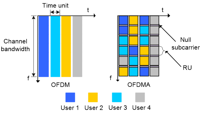
OFDMA
802.11a, 802.11g, 802.11n, and 802.11ac use Orthogonal Frequency Division Multiplexing (OFDM) in data transmission to enable a single user to transmit data on all subcarriers at a given period of time. Based on OFDM, Orthogonal Frequency Division Multiple Access (OFDMA) splits a channel into sub-channels, known as resource units (RUs), with specific subcarriers (tones), and assigns different RUs to different users for simultaneous transmission. This increases the data rate and reduces transmission latency.
802.11ax uses OFDMA and reserves some null subcarriers to reduce inter-subcarrier interference on RUs.
Figure 1 OFDM and OFDMA working modes
MU-MIMO
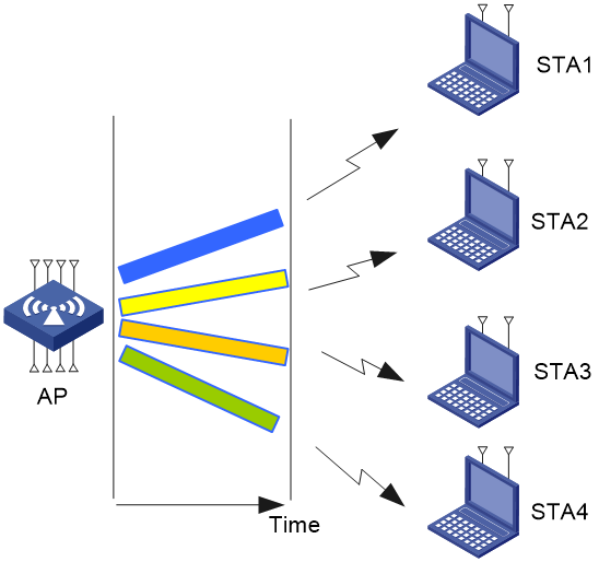
Multi-user multiple-input multiple-output (MU-MIMO) splits bandwidth into individual streams to enable simultaneous receiving and transmission of data for multiple users. 802.11ac supports only downlink MU-MIMO with a maximum of 4 streams, and 802.11ax supports both uplink and downlink MU-MIMO with a maximum of 8 streams. This greatly improves data transmission efficiency.
· In downlink MU-MIMO, APs use beamforming to direct packets to wireless clients at different locations for the clients to receive data from an AP at the same time.
Figure 2 Downlink MU-MIMO
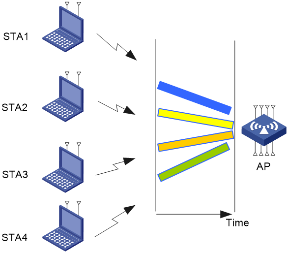
· In uplink MU-MIMO, the system uses the orthogonality of different client locations to achieve spatial separation and beamforming exchanges are avoided.
Figure 3 Uplink MU-MIMO
Restrictions: Hardware compatibility with radio management
Support for the 6 GHz band depends on the AP model and local regulations.
Some tri-band APs support all three radios operating in the 5 GHz band (with radio 1 in 5.15 GHz to 5.35 GHz, radio 2 in 5.47 GHz to 5.85 GHz, and radio 3 in 5.15 GHz to 5.35 GHz or 5.47 GHz to 5.85 GHz). In this case, radio 3 is used only for scanning and is not recommended for service configuration.
Restrictions: Radio mode compatibility
According to the IEEE-defined 802.11 wireless network communication standard, the main radio modes from oldest to newest are 802.11b, 802.11g, 802.11n, 802.11ac, 802.11ax, and 802.11be. Unless otherwise specified, newly released radio modes are compatible with the functions of previous radio modes.
Radio management tasks at a glance
To configure radio management, perform the following tasks:
· Enabling or disabling a radio interface
· Configuring basic radio functions
· (Optional.) Configuring 802.11n functions
· (Optional.) Configuring 802.11ac functions
· (Optional.) Configuring 802.11ax functions
· (Optional.) Configure 802.11be functions
· (Optional.) Disabling radar avoidance
Enabling or disabling a radio interface
1. Enter system view.
system-view
2. Enter radio interface view.
interface wlan-radio interface-number
3. Enable or disable the radio interface.
¡ Enable
the radio interface:
undo
shutdown
¡ Disable the radio interface:
shutdown
By default, a radio interface is enabled.
Specifying a radio mode
About this task
Available radio functions vary by radio mode:
· For 802.11a, 802.11b, and 802.11g radios, you can configure basic radio functions.
· For 802.11an and 802.11gn radios, you can configure basic radio functions and 802.11n functions.
· For 802.11ac radios, you can configure basic radio functions, 802.11n functions, and 802.11ac functions.
· For 802.11ax, 802.11gax, and 802.11eax radios, you can configure basic radio functions, 802.11n functions, 802.11ac functions, and 802.11ax functions.
· For 802.11be, 802.11abe, and 802.11gbe radios, you can configure basic radio functions, 802.11n functions, 802.11ac functions, 802.11ax functions, and 802.11be functions.
Restrictions and guidelines
Support for channels and transmit powers depends on the radio mode. When you change the mode of a radio, the system automatically adjusts the channel and power parameters for the radio.
Some devices support switching the operating frequency band of radios from 5GHz to 6GHz. If the bound wireless service does not support 6GHz radios, the system unbinds the wireless service automatically. A wireless service supports 6GHz when either of the following features are configured:
· Enhanced open-system authentication (enhanced-open enable).
· WPA3-SAE in mandatory mode (wpa3 personal mandatory) and H2E method for PWE deriving (akm sae pwe h2e).
· WPA3-Enterprise in 192-bit mode (wpa3 enterprise).
· WPA3-Enterprise in mandatory mode (wpa3 enterprise-only-mode).
Procedure
1. Enter system view.
system-view
2. Enter radio interface view.
interface wlan-radio interface-number
3. Specify a radio mode.
type { dot11a | dot11abe | dot11ac | dot11an | dot11ax | dot11b | dot11be | dot11eax | dot11g | dot11gax | dot11gbe | dot11gn }
For information about the default setting, see Radio Resources Management Command Reference.
Configuring basic radio functions
Specifying a working channel
About this task
Perform this task to reduce interference from both wireless and non-wireless devices. You can manually specify a channel or configure the system to automatically select a channel for a radio.
When radar signals are detected on the working channel of a radio, one of the following events occurs:
· If the channel is automatically assigned, the radio changes its channel.
· If the channel is manually specified, the radio changes its channel, and switches back to the specified channel after 30 minutes and then starts the quiet timer. If no radar signals are detected within the quiet time, the radio starts to use the channel. If radar signals are detected within the quiet time, the radio changes it channel again.
Procedure
1. Enter system view.
system-view
2. Enter radio interface view.
interface wlan-radio interface-number
3. Specify a working channel.
channel { channel-number | auto }
By default, the AP automatically selects a working channel for a radio interface.
Setting the antenna type
About this task
You can perform this task to specify the antenna type of an H3C antenna or a third-party antenna.
· When an H3C antenna is used, make sure the antenna type is consistent with the actual type of the antenna used on the AP.
· When a third-party antenna is used, make sure the antenna gain is the actual gain of the third-party antenna.
Restrictions and guidelines
Support for antenna types depends on the AP model.
Procedure
1. Enter system view.
system-view
2. Enter radio interface view.
interface wlan-radio interface-number
3. Set the antenna type.
antenna type { antenna-type | custom gain custom-gain }
By default, the antenna type is internal.
Setting the maximum transmit power
Restrictions and guidelines
The transmit power range supported by a radio varies by region code, channel, AP model, radio mode, antenna type, and bandwidth mode. If you change these attributes for a radio after you set the maximum transmit power, the configured maximum transmit power might be out of the supported transmit power range. If this happens, the system automatically adjusts the maximum transmit power to a valid value.
Procedure
1. Enter system view.
system-view
2. Enter radio interface view.
interface wlan-radio interface-number
3. Set the maximum transmit power.
max-power radio-power
By default, a radio interface uses the supported maximum transmit power.
Setting transmission rates
About this task
Transmission rates are classified into the following types:
· Prohibited rates—Rates that cannot be used by an AP.
· Mandatory rates—Rates that the clients must support to associate with an AP.
· Supported rates—Rates that an AP supports. After a client associates with an AP, the client can select a higher rate from the supported rates to communicate with the AP. The AP automatically decreases or increases the transmission rate as interference signals, retransmission packets, or dropped packets increase or decrease.
· Multicast rate—Rate at which an AP transmits multicasts and broadcasts. The multicast rate must be selected from the mandatory rates.
Procedure
1. Enter system view.
system-view
2. Enter radio interface view.
interface wlan-radio interface-number
3. Set the transmission rates for the radio.
rate { multicast { auto | rate-value } | { disabled | mandatory | supported } rate-value }
The default settings are as follows:
¡ 802.11be/802.11eax radios:
- Prohibited rates—None.
- Mandatory rates—6, 12, 24, 18, and 36.
- Multicast rate—Selected from the mandatory rates.
- Supported rates—9, 18, 36, 48, and 54.
¡ 802.11a/802.11an/802.11ac/802.11ax/802.11abe radios:
- Prohibited rates—None.
- Mandatory rates—6, 12, and 24.
- Multicast rate—Selected from the mandatory rates.
- Supported rates—9, 18, 36, 48, and 54.
¡ 802.11b radios:
- Prohibited rates—None.
- Mandatory rates—1 and 2.
- Multicast rate—Selected from the mandatory rates.
- Supported rates—5.5, and 11.
¡ 802.11g/802.11gn/802.11gax/802.11gbe radios:
- Prohibited rates—None.
- Mandatory rates—1, 2, 5.5, and 11.
- Multicast rate—Selected from the mandatory rates.
- Supported rates—6, 9, 12, 18, 24, 36, 48, and 54.
Setting the beacon interval
About this task
Perform this task to enable an AP to broadcast beacon frames at the specified interval. A short beacon interval enables clients to easily detect the AP but consumes more system resources.
Procedure
1. Enter system view.
system-view
2. Enter radio interface view.
interface wlan-radio interface-number
3. Set the beacon interval.
beacon-interval interval
By default, the beacon interval is 100 TU.
Setting the DTIM interval
About this task
An AP periodically broadcasts a beacon compliant with the Delivery Traffic Indication Map (DTIM). After the AP broadcasts the beacon, it sends buffered broadcast and multicast frames based on the value of the DTIM interval. For example, if you set the DTIM interval to 5, the AP sends buffered broadcast and multicast frames every five beacon frames.
Hardware and feature compatibility
|
Hardware series |
Model |
Feature compatibility |
|
WA7200 series |
WA7220 WA7220-HI WA7220H WA7226-C WA7230 WA7230-LI |
No |
|
WA7300 series |
WA7320i WA7322H-HI WA7330X WA7338-HI |
Yes |
|
WA7500 series |
WA7538 WA7539 |
Yes |
|
WA7600 series |
WA7638 |
No |
Procedure
1. Enter system view.
system-view
2. Enter radio interface view.
interface wlan-radio interface-number
3. Set the DTIM interval.
dtim counter
By default, the DTIM interval is 1.
Setting the maximum number of clients that can associate with an AP
About this task
When the maximum number of clients is reached on an AP, the AP stops accepting new clients and the SSID will be automatically hidden. This prevents the AP from being overloaded.
Procedure
1. Enter system view.
system-view
2. Enter radio interface view.
interface wlan-radio interface-number
3. Set the maximum number of clients that can associate with the AP.
client max-count max-number
By default, no limit is set for the number of clients that can associate with an AP.
Setting the maximum transmission distance
About this task
The strength of wireless signals gradually degrades as the transmission distance increases. The maximum transmission distance of wireless signals depends on the surrounding environment and on whether an external antenna is used.
· Without an external antenna—About 300 meters (984.25 ft).
· With an external antenna—30 km (18.64 miles) to 50 km (31.07 miles).
· In an area with obstacles—35 m (114.83 ft) to 50 m (164.04 ft).
Procedure
1. Enter system view.
system-view
2. Enter radio interface view.
interface wlan-radio interface-number
3. Set the maximum transmission distance.
distance distance
By default, the maximum transmission distance is 1 km (0.62 miles).
Performing on-demand channel usage measurement
About this task
This feature enables an AP to scan supported channels and display the channel usage after scanning. It takes about one second to scan a channel.
Procedure
1. Enter system view.
system-view
2. Enter radio interface view.
interface wlan-radio interface-number
3. Perform on-demand channel usage measurement.
channel-usage measure
Configuring 802.11n functions
Configuring the A-MPDU aggregation method
About this task
A MAC Protocol Data Unit (MPDU) is a data frame in 802.11 format. MPDU aggregation aggregates multiple MPDUs into one aggregate MPDU (A-MPDU) to reduce additional information, ACK frames, and Physical Layer Convergence Procedure (PLCP) header overhead. This improves network throughput and channel efficiency.
All MPDUs in an A-MPDU must have the same QoS priority, source address, and destination address.
Procedure
1. Enter system view.
system-view
2. Enter radio interface view.
interface wlan-radio interface-number
3. Configure the A-MPDU aggregation method.
a-mpdu { disable | enable }
By default, the A-MPDU aggregation method is enabled.
Configuring the A-MSDU aggregation method
About this task
MSDU aggregation aggregates multiple MSDUs into one aggregate MSDU (A-MSDU) to reduce PLCP preamble, PLCP header, and MAC header overheads. This improves network throughput and frame forwarding efficiency.
All MSDUs in an A-MSDU must have the same QoS priority, source address, and destination address. When a device receives an A-MSDU, it restores the A-MSDU to multiple MSDUs for processing.
Procedure
1. Enter system view.
system-view
2. Enter radio interface view.
interface wlan-radio interface-number
3. Configure the A-MSDU aggregation method.
a-msdu { disable | enable }
By default, the A-MSDU aggregation method is enabled.
Configuring short GI
About this task
802.11 OFDM fragments frames to data blocks for transmission. It uses GI to ensure that the data block transmissions do not interfere with each other and are immune to transmission delays.
The GI used by 802.11a/g and 802.11ax is 800 ns. 802.11n supports a short GI of 400 ns, which provides a 10% increase in data rate.
Both the 20 MHz and 40 MHz bandwidth modes support short GI.
Procedure
1. Enter system view.
system-view
2. Enter radio interface view.
interface wlan-radio interface-number
3. Configure short GI.
short-gi { disable | enable }
By default, short GI is enabled.
Configuring LDPC
About this task
802.11n introduces the Low-Density Parity Check (LDPC) mechanism to increase the signal-to-noise ratio and enhance transmission quality. LDPC takes effect only when both ends support LDPC.
Procedure
1. Enter system view.
system-view
2. Enter radio interface view.
interface wlan-radio interface-number
3. Configure LDPC.
ldpc { disable | enable }
By default, LDPC is enabled.
Configuring STBC
About this task
The Space-Time Block Coding (STBC) mechanism enhances the reliability of data transmission and does not require clients to have high transmission rates.
Procedure
1. Enter system view.
system-view
2. Enter radio interface view.
interface wlan-radio interface-number
3. Configure STBC.
stbc { disable | enable }
By default, STBC is enabled.
Setting MCS indexes
About this task
802.11n clients use the rate corresponding to the MCS index to send unicast frames. 802.11a/b/g clients use the 802.11a/b/g rate to send unicast frames.
If you do not set a multicast MCS index, 802.11n clients and the AP use the 802.11a/b/g multicast rate to send multicast frames. If you set a multicast MCS index, one of following events occurs:
· The AP and clients use the rate corresponding to the multicast MCS index to send multicast frames if only 802.11n and 802.11ac clients exist.
· The AP and clients use the 802.11a/b/g multicast rate to send multicast frames if any 802.11a/b/g clients exist.
When you set the maximum mandatory or supported MCS index, you are specifying a range. For example, if you set the maximum mandatory MCS index to 5, rates corresponding to MCS indexes 0 through 5 are configured as 802.11n mandatory rates.
Restrictions and guidelines
The multicast MCS index cannot be greater than the maximum mandatory MCS index.
The maximum supported MCS index cannot be smaller than the maximum mandatory MCS index.
The multicast MCS index cannot be greater than the maximum supported MCS index.
Procedure
1. Enter system view.
system-view
2. Enter radio interface view.
interface wlan-radio interface-number
3. Set the maximum mandatory MCS index.
dot11n mandatory maximum-mcs index
By default, no maximum mandatory MCS index is set.
4. Set the maximum supported MCS index.
dot11n support maximum-mcs index
By default, the maximum supported MCS index is 76.
5. Set the multicast MCS index.
dot11n multicast-mcs index
By default, no multicast MCS index is set.
Configuring the client dot11n-only feature
About this task
To prevent low-speed 802.11a/b/g clients from decreasing wireless data transmission performance, you can enable the client dot11n-only feature for an AP to accept only 802.11n clients and clients of higher standards.
Procedure
1. Enter system view.
system-view
2. Enter radio interface view.
interface wlan-radio interface-number
3. Configure the client dot11n-only feature.
client dot11n-only { disable | enable }
By default, the client dot11n-only feature is disabled.
Setting the 802.11n bandwidth mode
About this task
802.11n uses the channel structure of 802.11a/b/g, but it increases the number of data subchannels in each 20 MHz channel to 52. This improves data transmission rate.
802.11n binds two adjacent 20 MHz channels to form a 40 MHz channel (one primary channel and one secondary channel). This provides a simple way to double the data rate.
If the current channel of a radio does not support the specified bandwidth mode, the radio clears the channel configuration and selects another channel.
If the bandwidth mode is set to 40 MHz, the radio uses the 40 MHz bandwidth if two adjacent channels that can be bound together exist. If there are no adjacent channels that can be bound together, the radio uses the 20 MHz bandwidth.
Procedure
1. Enter system view.
system-view
2. Enter radio interface view.
interface wlan-radio interface-number
3. Set the 802.11n bandwidth mode.
channel band-width { 20 | 40 [ auto-switch ] }
By default, the bandwidth mode is 40 MHz for 802.11an radios and 20 MHz for 802.11gn radios.
Only 802.11gn radios support the auto-switch keyword.
Specifying a MIMO mode
|
|
NOTE: The number of spatial streams supported by a radio varies by AP model. |
About this task
Multiple-input and multiple-output (MIMO) enables a radio to send and receive wireless signals through multiple spatial streams. This improves system capacity and spectrum usage without requiring higher bandwidth.
A radio can operate in one of the following MIMO modes:
· 1x1—Sends and receives wireless signals through one spatial stream.
· 2x2—Sends and receives wireless signals through two spatial streams.
· 3x3—Sends and receives wireless signals through three spatial streams.
· 4x4—Sends and receives wireless signals through four spatial streams.
· 5x5—Sends and receives wireless signals through five spatial streams.
· 6x6—Sends and receives wireless signals through six spatial streams.
· 7x7—Sends and receives wireless signals through seven spatial streams.
· 8x8—Sends and receives wireless signals through eight spatial streams.
Procedure
1. Enter system view.
system-view
2. Enter radio interface view.
interface wlan-radio interface-number
3. Specify a MIMO mode.
mimo { 1x1 | 2x2 | 3x3 | 4x4 | 5x5 | 6x6 | 7x7 | 8x8 }
The default MIMO mode for a radio varies by AP model.
Configuring energy saving
About this task
After you enable the energy-saving feature, the MIMO mode of a radio automatically changes to 1x1 if no clients associate with the radio and the radio is not enabled with WIPS.
Procedure
1. Enter system view.
system-view
2. Enter radio interface view.
interface wlan-radio interface-number
3. Configure energy saving.
green-energy-management { disable | enable }
By default, energy saving is disabled.
Configuring 802.11ac functions
Setting NSSs
About this task
If the AP supports an NSS, it supports all VHT-MCS indexes for the NSS. 802.11ac clients use the rate corresponding to the VHT-MCS index for the NSS to send unicast frames. Non-802.11ac clients use the 802.11a/b/g/n rate to send unicast frames.
If you do not set a multicast NSS, 802.11ac clients and the AP use the 802.11a/b/g/n multicast rate to send multicast frames. If you set a multicast NSS and specify a VHT-MCS index, the following situations occur:
· The AP and clients use the rate corresponding to the VHT-MCS index to send multicast frames if all clients are 802.11ac clients.
· The AP and clients use the 802.11a/b/g/n multicast rate to send multicast frames if any non-802.11ac clients exist.
The maximum mandatory NSS or supported NSS determines a range of 802.11 rates. For example, if the maximum mandatory NSS is 5, rates corresponding to VHT-MCS indexes for NSSs 1 through 5 will be 802.11ac mandatory rates.
Restrictions and guidelines
The maximum supported NSS cannot be smaller than the maximum mandatory NSS and the multicast NSS cannot be greater than the maximum mandatory NSS.
Procedure
1. Enter system view.
system-view
2. Enter radio interface view.
interface wlan-radio interface-number
3. Set the maximum mandatory NSS.
dot11ac mandatory maximum-nss nss-number
By default, no maximum mandatory NSS is set.
4. Set the maximum supported NSS.
dot11ac support maximum-nss nss-number
By default, the maximum supported NSS is 8.
5. Set the multicast NSS and specify a VHT-MCS index.
dot11ac multicast-nss nss-number vht-mcs index
By default, no multicast NSS is set.
Configuring the client dot11ac-only feature
About this task
To prevent low-speed 802.11a/b/g/n clients from decreasing wireless data transmission performance, you can enable the client dot11ac-only feature for an AP to accept only 802.11ac clients and clients of higher standards.
Procedure
1. Enter system view.
system-view
2. Enter radio interface view.
interface wlan-radio interface-number
3. Configure the client dot11ac-only feature.
client dot11ac-only { disable | enable }
By default, the client dot11ac-only feature is disabled.
Setting the 802.11ac bandwidth mode
About this task
802.11ac uses the channel structure of 802.11n and increases the maximum bandwidth from 40 MHz to 160 MHz. 802.11ac can bind two adjacent 20/40/80 MHz channels to form a 40/80/160 MHz channel.
The radio uses the specified 40/80/160 MHz bandwidth if adjacent channels can be bound to form a 40/80/160 channel. If adjacent channels cannot form a 40/80/160 channel, the radio uses the next available bandwidth less than the specified one.
If the working channel is specified and the actual working bandwidth is 160 MHz, the device automatically selects a secondary channel. The working channel forwards all packets and the secondary channel forwards only data packets.
If the current channel of a radio does not support the specified bandwidth mode, the radio clears the channel configuration and selects another channel.
Figure 4 802.11ac bandwidth modes

Procedure
1. Enter system view.
system-view
2. Enter radio interface view.
interface wlan-radio interface-number
3. Set the 802.11ac bandwidth mode:
channel band-width { 20 | 40 | 80 | 160 }
Execute this command in the view of a 5 GHz radio interface.
By default, the bandwidth mode is 80 MHz for 802.11ac radios.
Configuring TxBF
About this task
Transmit beamforming (TxBF) enables an AP to adjust transmitting parameters based on the channel information to focus RF signals on intended clients. This feature improves the RF signal quality. TxBF includes single-user TxBF and multi-user TxBF.
· Single-user TxBF—Single-user TxBF enables an AP to improve the signal to one intended client. Single-user TxBF is applicable to WLANs that have widely spread clients, poor network quality, and serious signal attenuation.
· Multi-user TxBF—Multi-user TxBF is part of 802.11ac Wave2. Multi-user TxBF enables an AP to focus different RF signals on their intended clients to reduce interference and transmission delay. This improves traffic throughput and bandwidth usage. Multi-user TxBF is applicable to WLANs that have a large number of clients and require high bandwidth usage and low transmission delay.
Procedure
1. Enter system view.
system-view
2. Enter radio interface view.
interface wlan-radio interface-number
3. Configure single-user TxBF.
su-txbf { disable | enable }
By default, single-user TxBF is disabled.
4. Configure multi-user TxBF.
mu-txbf { disable | enable }
By default, multi-user TxBF is disabled.
Multi-user TxBF takes effect only when single-user TxBF is enabled.
Configuring 802.11ax functions
Setting NSSs
About this task
If an AP supports an NSS, it supports all HE-MCS indexes for the NSS. 802.11ax clients that use the rate corresponding to the HE-MCS index for the NSS to send unicast frames. Non-802.11ax clients use the 802.11a/b/g/n/ac rate to send unicast frames.
If you do not set a multicast NSS, 802.11ax clients and the AP use the 802.11a/b/g/n/ac multicast rate to send multicast frames. If you set a multicast NSS and specify an HE-MCS index, the following situations occur:
· The AP and clients use the rate corresponding to the HE-MCS index to send multicast frames if all clients are 802.11ax clients.
· The AP and clients use the 802.11a/b/g/n/ac multicast rate to send multicast frames if any non-802.11ax clients exist.
The maximum mandatory NSS or supported NSS determines a range of 802.11 rates. For example, if the maximum mandatory NSS is 5, rates corresponding to HE-MCS indexes for NSSs 1 through 5 will be 802.11ax mandatory rates.
Restrictions and guidelines
The maximum supported NSS cannot be smaller than the maximum mandatory NSS and the multicast NSS cannot be greater than the maximum mandatory NSS.
Procedure
1. Enter system view.
system-view
2. Enter radio interface view.
interface wlan-radio interface-number
3. Set the maximum mandatory NSS.
dot11ax mandatory maximum-nss nss-number
By default, no maximum mandatory NSS is set.
4. Set the maximum supported NSS.
dot11ax support maximum-nss nss-number
By default, the maximum supported NSS is 8.
5. Set the multicast NSS and specify an HE-MCS index.
dot11ax multicast-nss nss-number he-mcs index
By default, no multicast NSS is set.
Configuring the client dot11ax-only feature
About this task
To prevent low-speed 802.11a/b/g/n/ac clients from decreasing wireless data transmission performance, you can enable the client dot11ax-only feature for an AP to accept only 802.11ax clients and clients of higher standards.
Procedure
1. Enter system view.
system-view
2. Enter radio interface view.
interface wlan-radio interface-number
3. Configure the client dot11ax-only feature.
client dot11ax-only { disable | enable }
By default, the client dot11ax-only feature is disabled.
Setting the 802.11ax bandwidth mode
About this task
802.11ax uses the channel structure of 802.11n and increases the maximum bandwidth from 40 MHz to 160 MHz. 802.11ax can bind two adjacent 20/40/80 MHz channels to form a 40/80/160 MHz channel.
The radio uses the specified 40/80/160 MHz bandwidth if adjacent channels can be bound to form a 40/80/160 channel. If adjacent channels cannot form a 40/80/160 channel, the radio uses the next available bandwidth lower than the specified one.
If a working channel is specified for the 160 MHz bandwidth mode, the device automatically selects a secondary channel. The working channel forwards all packets and the secondary channel forwards only data packets.
If the current channel of a radio does not support the specified bandwidth mode, the radio clears the channel configuration and selects another channel.
Figure 5 802.11ax bandwidth modes

Restrictions and guidelines
802.11gax supports only the 20 MHz and 40 MHz bandwidth modes.
Procedure
1. Enter system view.
system-view
2. Enter radio interface view.
interface wlan-radio interface-number
3. Set the 802.11ax bandwidth mode:
channel band-width { 20 | 40 | 80 | 160 }
Execute this command in the view of a 5 GHz radio interface.
By default, the bandwidth mode is 80 MHz for 802.11ax radios.
4. Set the 802.11gax bandwidth mode:
channel band-width { 20 | 40 [ auto-switch ] }
Execute this command in the view of a 2.4 GHz radio interface.
By default, the bandwidth mode is 20 MHz for 802.11gax radios.
Configuring OFDMA
About this task
OFDMA can provide the following benefits if enabled in a high density environment where small data packets are transmitted:
· Concurrent transmission to multiple users.
· Improved radio usage.
· Shortened transmission latency.
· Reduced conflict backoff.
Procedure
1. Enter system view.
system-view
2. Enter radio interface view.
interface wlan-radio interface-number
3. Configure downlink OFDMA.
dl-ofdma { disable | enable }
By default, downlink OFDMA is disabled.
4. Configure uplink OFDMA.
ul-ofdma { disable | enable }
By default, uplink OFDMA is disabled.
Configuring uplink MU-MIMO
About this task
Uplink MU-MIMO enables an AP to receive data packets from multiple clients concurrently. With this feature enabled, an AP sends an HE_Trig message to all associated clients to inform the transmission time, frequency, sampling clock, and power requirements. Upon receiving the message, clients send data packets to the AP as required at the same time.
This feature is applicable to scenarios that have a large number of clients and high AP bandwidth usage and transmission latency requirements.
Restrictions and guidelines
Only radios enabled with the client mode support this feature.
Procedure
1. Enter system view.
system-view
2. Enter radio interface view.
interface wlan-radio interface-number
3. Configure uplink MU-MIMO.
ul-mu-mimo { disable | enable }
By default, uplink MU-MIMO is disabled.
Configuring BSS coloring
About this task
BSS coloring enables the system to assign a color to each BSS and include the color ID in data packets for clients to identify if a packet comes from the associated AP. To avoid conflicts, clients that detect an 802.11ax data packet with the same color as its associated BSS will postpone transmission.
Hardware and feature compatibility
|
Hardware series |
Model |
Feature compatibility |
|
WA7200 series |
WA7220 WA7220-HI WA7220H WA7226-C WA7230 WA7230-LI |
No |
|
WA7300 series |
WA7320i WA7322H-HI WA7330X WA7338-HI |
Yes |
|
WA7500 series |
WA7538 WA7539 |
Yes |
|
WA7600 series |
WA7638 |
No |
Procedure
1. Enter system view.
system-view
2. Enter radio interface view.
interface wlan-radio interface-number
3. Configure BSS coloring.
bss-color { disable | enable }
By default, BSS coloring is disabled.
Configuring TWT negotiation
About this task
Target Wake Time (TWT) negotiation enables clients and APs to exchange data packets only in service periods and schedules client hibernation to reduce client power consumption and wireless resource competition.
With TWT negotiation enabled, clients send negotiation requests that carry the service period, TWT interval, and first wake time (calculated by clients) to APs. Upon receiving such a request, an AP sends a response. Then, the clients wake up as scheduled and wait for trigger frames from that AP. Upon receiving a trigger frame, clients enter a service period and start to exchange data packets with that AP. When a service period expires, clients enter hibernation mode even if data packet exchange is not finished.
Hardware and feature compatibility
|
Hardware series |
Model |
Feature compatibility |
|
WA7200 series |
WA7220 WA7220-HI WA7220H WA7226-C WA7230 WA7230-LI |
No |
|
WA7300 series |
WA7320i WA7322H-HI WA7330X WA7338-HI |
Yes |
|
WA7500 series |
WA7538 WA7539 |
Yes |
|
WA7600 series |
WA7638 |
No |
Restrictions and guidelines
A radio can provide the TWT service to a maximum of eight clients. After responding to the TWT negotiation requests of eight clients, the radio rejects the requests from the other clients.
This feature takes effect only on 802.11ax radios. Changing the radio mode to a non-802.11ax mode removes the configuration.
Procedure
1. Enter system view.
system-view
2. Enter radio interface view.
interface wlan-radio interface-number
3. Configure TWT negotiation.
twt negotiate { disable | enable }
The default setting varies by AP model.
Configure 802.11be functions
Setting NSSs
About this task
When an 802.11be client comes online, the system uses the MCS represented by the EHT-MCS index corresponding to the NSS to transmit the unicast data of the client.
When the multicast NSS is not configured, the system uses the multicast rate or the multicast MCS to transmit multicast data between the 802.11be client and the AP.
When the multicast NSS is configured and all clients are 802.11be clients, the AP and clients use the MCS represented by the EHT-MCS index to transmit multicast data.
Restrictions and guidelines
The multicast NSS must be less than or equal to the maximum mandatory NSS, and the maximum mandatory NSS must be less than or equal to the maximum supported NSS.
Procedure
1. Enter system view.
system-view
2. Enter radio interface view.
interface wlan-radio interface-number
3. Set the maximum mandatory NSS for 802.11be.
dot11be mandatory maximum-nss nss-number
By default, the maximum mandatory NSS is not set.
4. Set the maximum supported NSS for 802.11be.
dot11be support maximum-nss nss-number
By default, the maximum supported NSS is 8.
5. Set the multicast NSS and specify an EHT-MCS index for 802.11be.
dot11be multicast-nss nss-number eht-mcs index
By default, the multicast NSS is not set and the EHT-MCS index is not specified either.
Setting the 802.11be bandwidth mode
About this task
Compared with 802.11ax, 802.11be increases the channel bandwidth from a maximum of 160 MHz to a maximum of 320 MHz. 802.11be adopts the channel bandwidth allocation method from 802.11n, where larger bandwidth channels are obtained by merging adjacent channels. In 802.11be, two adjacent 20 MHz channels can be merged to form a 40 MHz channel, and 80 MHz and 160 MHz channels can also be merged in the same way.
Figure 6 802.11be bandwidth modes

Procedure
1. Enter system view.
system-view
2. Enter radio interface view.
interface wlan-radio interface-number
3. Set the 802.11be bandwidth mode.
channel band-width { 20 | 40 | 80 | 160 | 320 }
Execute this command only for 6 GHz radios.
By default, the default bandwidth mode is 80 MHz.
4. Set the 802.11abe bandwidth mode.
channel band-width { 20 | 40 | 80 | 160 }
Execute this command only for 5 GHz radios.
By default, the default bandwidth mode is 80 MHz.
5. Set the 802.11gbe bandwidth mode.
channel band-width { 20 | 40 [ auto-switch ] }
Execute this command only for 2.4 GHz radios.
By default, the default bandwidth mode is 20 MHz.
Configuring MRU
About this task
Multiple Resource Unit (MRU) is a technology that increases the spectral resource usage rate, mainly used in multi-user scenarios.
In Wi-Fi6 (802.11ax), each user can only use one RU. In Wi-Fi7 (802.11be), the concept of MRU is introduced to allow a single user to use multiple RUs. As shown in Figure 7, under the same bandwidth, MRU allows a single client to occupy multiple RUs simultaneously when data is being transmitted to two users at the same time. This improves spectral resource usage and reduces latency. In Wi-Fi 6, a single client can only use the single RU resource allocated to it, resulting in a waste of spectral resources.
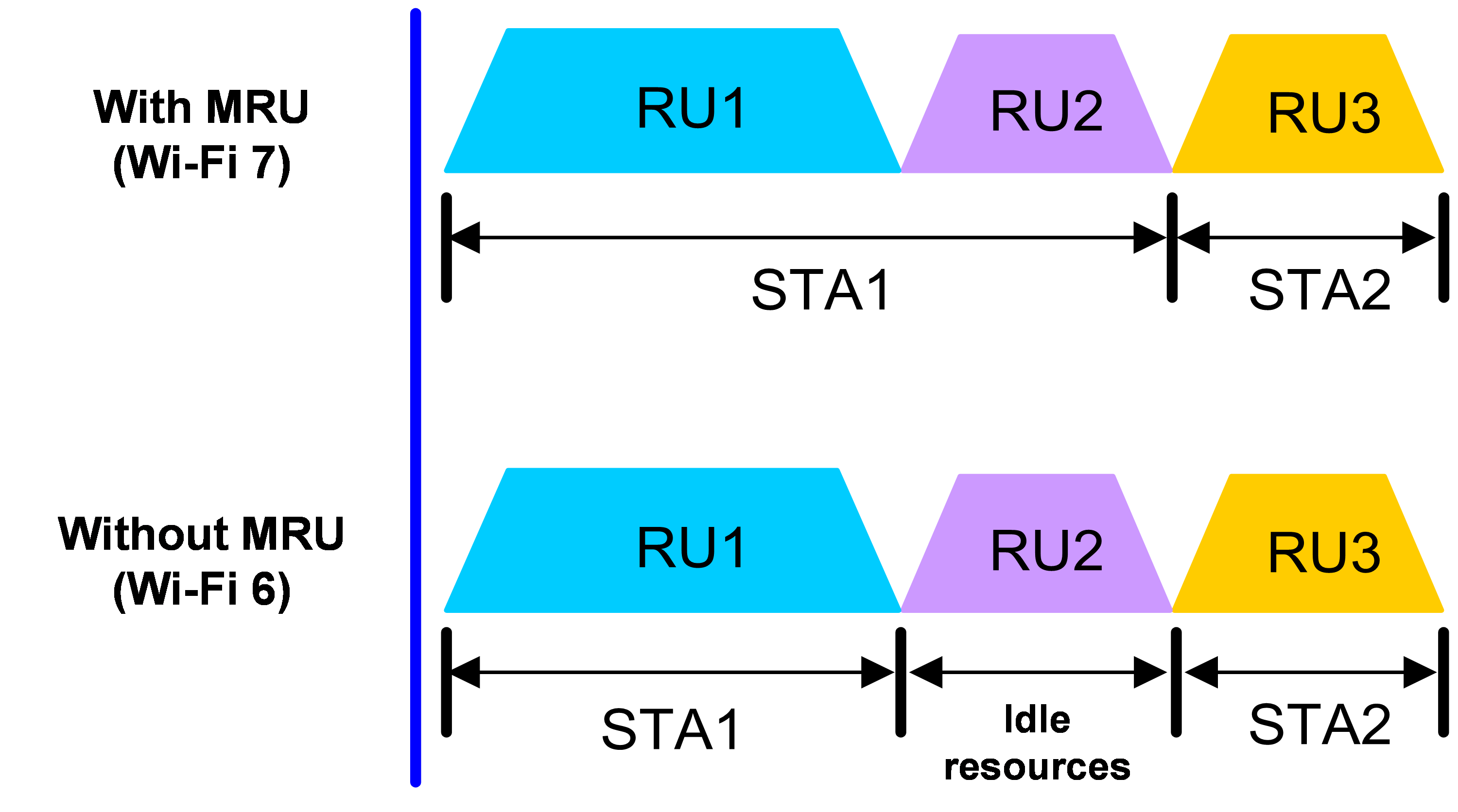
Hardware and feature compatibility
|
Hardware series |
Model |
Feature compatibility |
|
WA7200 series |
WA7220 WA7220-HI WA7220H WA7226-C WA7230 WA7230-LI |
No |
|
WA7300 series |
WA7320i WA7322H-HI WA7330X WA7338-HI |
Yes |
|
WA7500 series |
WA7538 WA7539 |
Yes |
|
WA7600 series |
WA7638 |
No |
Restrictions and guidelines
Changing the radio mode to a lower one cancels the configuration.
Procedure
1. Enter system view.
system-view
2. Enter radio interface view.
interface wlan-radio interface-number
3. Configure MRU.
mru { disable | enable }
By default, MRU is disabled.
Configuring preamble puncturing
About this task
The preamble puncturing technology enables data transmission using discontinuous channels to improve channel utilization efficiency. It is mainly used in scenarios with channel interference.
Without preamble puncturing, as shown in Figure 8, if the bandwidth mode is 80 MHz and interference is encountered on channel 56, the system uses the 20 MHz bandwidth mode instead for transmission. With preamble puncturing enabled, as shown in Figure 9, the interfered portion (channel 56) is punctured and shielded, and the remaining channels 52, 60, and 64 are bundled together for information transmission. Although the AP is still working in the 80 MHz bandwidth mode, the interfered channel is put in Null state (idle state) in actual transmission.
Preamble static puncturing refers to the software designating the puncturing positions based on the bandwidth mode and the position of the primary channel.
Figure 8 Without preamble puncturing
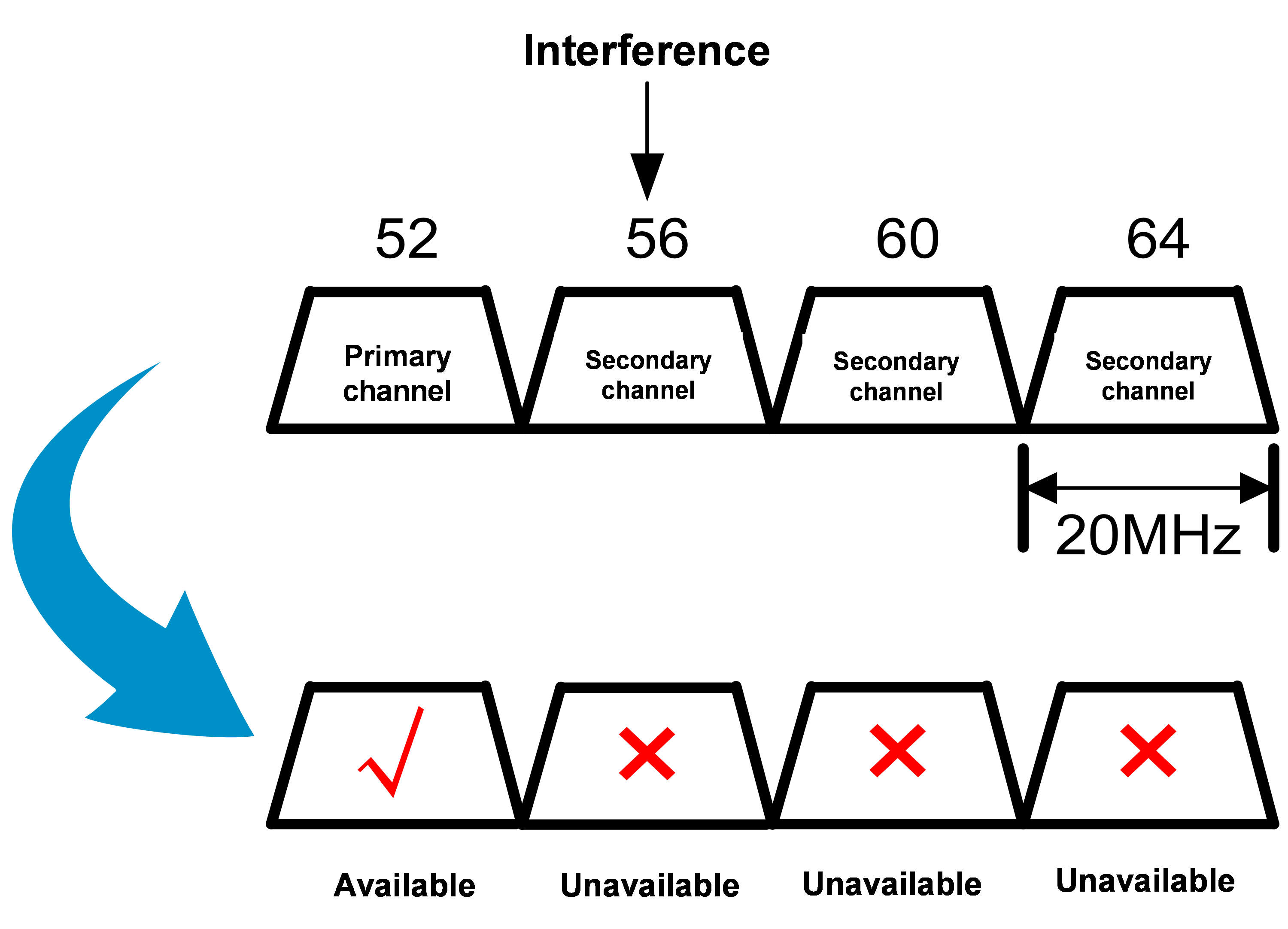
Figure 9 With preamble puncturing
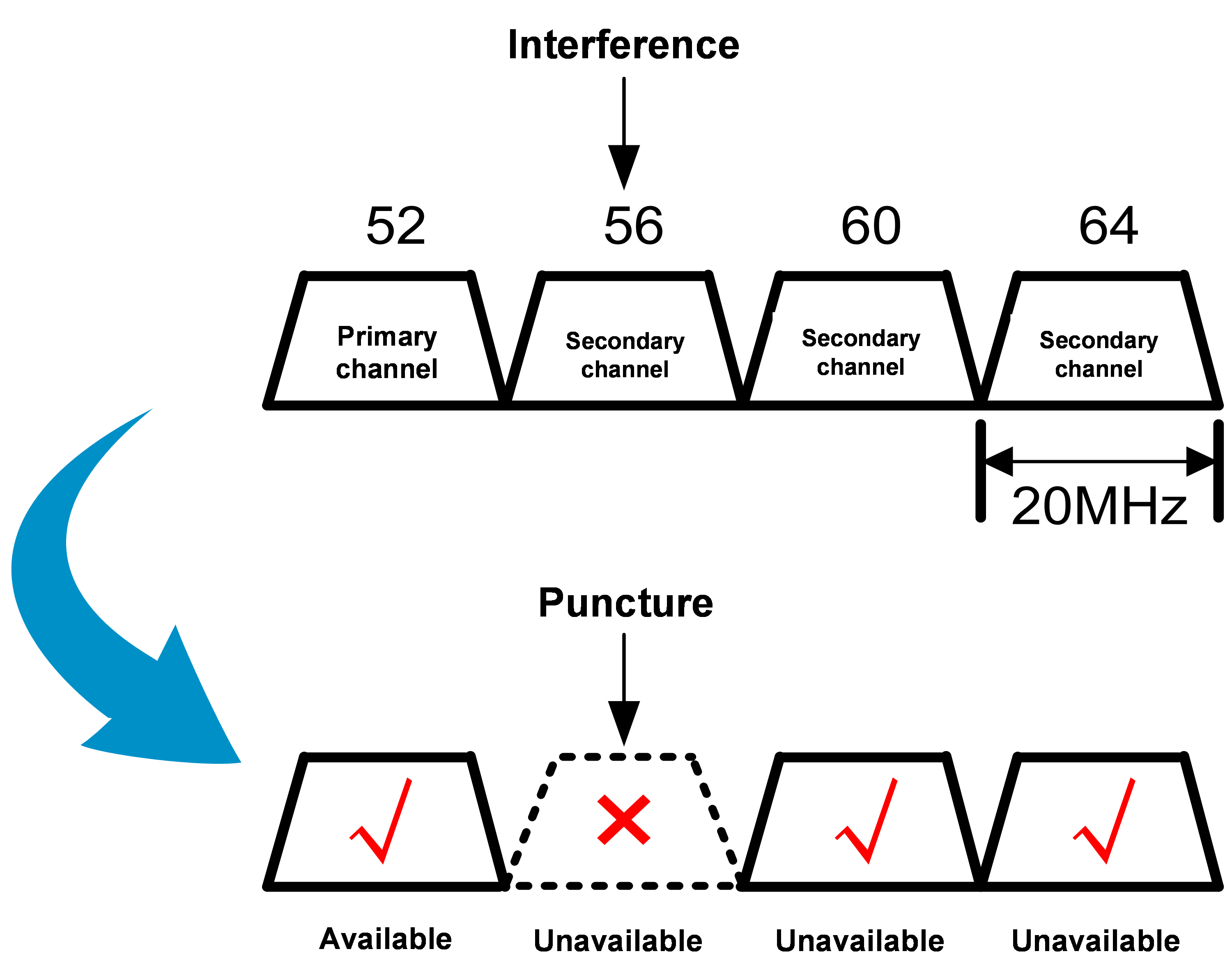
Hardware and feature compatibility
|
Hardware series |
Model |
Feature compatibility |
|
WA7200 series |
WA7220 WA7220-HI WA7220H WA7226-C WA7230 WA7230-LI |
No |
|
WA7300 series |
WA7320i WA7322H-HI WA7330X WA7338-HI |
Yes |
|
WA7500 series |
WA7538 WA7539 |
Yes |
|
WA7600 series |
WA7638 |
No |
Restrictions and guidelines
Preamble puncturing takes effect only when the bandwidth mode is 80 MHz or higher.
Changing the radio mode to a lower one cancels the configuration.
Procedure
1. Enter system view.
system-view
2. Enter radio interface view.
interface wlan-radio interface-number
3. Configure preamble puncturing.
pre-puncture static { disable | enable }
By default, preamble puncturing is disabled.
Disabling radar avoidance
About this task
Radar avoidance enables a radio to change its working channel or keep silent when radar signals are detected on the working channel, avoiding interference on radars. After 30 minutes, the radio switches back to the previous working channel or restarts transmission. If radar signals can still be detected, the radio changes its working channel or keeps silent again.
With radar avoidance disabled, radios continue to transmit or receive traffic on the working channels even if radar signals are detected on the channels.
Restrictions and guidelines
Disable radar avoidance only when you perform device debugging.
Procedure
1. Enter system view.
system-view
2. Enter radio interface view.
interface wlan-radio interface-number
3. Disable radar avoidance.
radar-detect disable
By default, radar avoidance is enabled.
Display and maintenance commands for radio management
Execute display commands in any view.
|
Task |
Command |
|
Display client information. |
display wlan client [ interface interface-type interface-number | mac-address mac-address | service-template service-template-name ] [ verbose ] |
|
Display radio information. |
display wlan ap radio radio-id |
Radio management configuration examples
The parameters configured in this example are for reference only. To achieve the best performance, configure the parameters based on your actual network requirements.
Example: Configuring basic radio functions
Network configuration
As shown in Figure 10, set the radio mode, working channel, and maximum transmit power to 802.11b, channel 36, and 19 dBm, respectively.

Procedure
# Enter radio interface view.
<AP> system-view
[AP] interface wlan-radio 1/0/1
# Set the radio mode to dot11b.
[AP-WLAN-Radio1/0/1] type dot11b
# Configure the radio to work on channel 36.
[AP-WLAN-Radio1/0/1] channel 36
# Set the maximum transmit power to 19 dBm.
[AP-WLAN-Radio1/0/1] max-power 19
Verifying the configuration
# Verify that the online clients are 802.11b clients.
[AP-WLAN-Radio1/0/1] display wlan client verbose
Total number of clients: 1
MAC address : 000f-e265-6400
IPv4 address : 10.1.1.114
IPv6 address : 2001::1234:5678:0102:0304
Username : N/A
AID : 1
AP ID : 1
AP name : ap1
Radio ID : 1
SSID : office
BSSID : 0026-3e08-1150
VLAN ID : 1
Power save mode : Active
Wireless mode : 802.11b
Supported rates : 1, 2 Mbps
QoS mode : WMM
Listen interval : 10
RSSI : 62
Rx/Tx rate : 130/11
Authentication method : Open system
Security mode : PRE-RSNA
AKM mode : N/A
Cipher suite : N/A
User authentication mode : Bypass
Authorization ACL ID : 3001(Not effective)
Authorization user profile : N/A
Authorization CAR : N/A
Roam status : N/A
Key derivation : SHA1
PMF status : Enabled
Forward policy : N/A
Online time : 0hr 1min 13sec
FT status : Inactive
Example: Configuring 802.11n
Network configuration
As shown in Figure 11, specify the radio as an 802.11an radio, and enable the A-MSDU and A-MPDU aggregation methods on the radio.

Procedure
# Enter radio interface view.
<AP> system-view
[AP] interface wlan-radio 1/0/1
# Set the radio mode to dot11an.
[AP-WLAN-Radio1/0/1] type dot11an
# Enable the A-MSDU and A-MPDU aggregation methods.
[AP-WLAN-Radio1/0/1] a-mpdu enable
[AP-WLAN-Radio1/0/1] a-msdu enable
# Enable the radio.
[AP-WLAN-Radio1/0/1] undo shutdown
Verifying the configuration
# Display client information.
[AP-WLAN-Radio1/0/1] display wlan client verbose
Total number of clients: 1
MAC address : 000f-e265-6400
IPv4 address : 10.1.1.114
IPv6 address : 2001::1234:5678:0102:0304
Username : N/A
AID : 1
AP ID : 1
AP name : ap1
Radio ID : 1
SSID : office
BSSID : 0026-3e08-1150
VLAN ID : 1
Power save mode : Active
Wireless mode : 802.11an
Supported rates : 1, 2 Mbps
QoS mode : WMM
Listen interval : 10
RSSI : 62
Rx/Tx rate : 130/11
Authentication method : Open system
Security mode : PRE-RSNA
AKM mode : N/A
Cipher suite : N/A
User authentication mode : Bypass
Authorization ACL ID : 3001(Not effective)
Authorization user profile : N/A
Authorization CAR : N/A
Roam status : N/A
Key derivation : SHA1
PMF status : Enabled
Forward policy : N/A
Online time : 0hr 1min 13sec
FT status : Inactive