- Table of Contents
-
- 05-Network Connectivity
- 00-Preface
- 01-About the network connectivity configuration guide
- 02-MAC address table configuration
- 03-VLAN configuration
- 04-Ethernet link aggregation configuration
- 05-Spanning tree configuration
- 06-LLDP configuration
- 07-Layer 2 forwarding configuration
- 08-PPP configuration
- 09-L2TP configuration
- 10-ARP configuration
- 11-IP addressing configuration
- 12-DHCP configuration
- 13-DHCPv6 configuration
- 14-DNS configuration
- 15-NAT configuration
- 16-IP performance optimization configuration
- 17-IPv6 basics configuration
- 18-Tunneling configuration
- 19-GRE configuration
- 20-ADVPN configuration
- 21-IP forwarding basics configuration
- 22-Basic IP routing configuration
- 23-Static routing configuration
- 24-IPv6 static routing configuration
- 25-Policy-based routing configuration
- 26-IPv6 policy-based routing configuration
- 27-RIP configuration
- 28-OSPF configuration
- 29-RIPng configuration
- 30-BGP configuration
- 31-Multicast overview
- 32-IGMP snooping configuration
- 33-MLD snooping configuration
- Related Documents
-
| Title | Size | Download |
|---|---|---|
| 28-OSPF configuration | 382.53 KB |
Restrictions and guidelines: OSPF configuration
Configuring basic OSPF functions
Configuring OSPF dynamic host name mappings
Display and maintenance commands for OSPF
Configuring OSPF
About OSPF
Open Shortest Path First (OSPF) is a link-state IGP developed by the OSPF working group of the IETF. OSPF version 2 is used for IPv4. OSPF refers to OSPFv2 throughout this chapter.
OSPF features
OSPF has the following features:
· Wide scope—Supports multiple network sizes and several hundred routers in an OSPF routing domain.
· Fast convergence—Advertises routing updates instantly upon network topology changes.
· Loop free—Computes routes with the SPF algorithm to avoid routing loops.
· Area-based network partition—Splits an AS into multiple areas to facilitate management. This feature reduces the LSDB size on routers to save memory and CPU resources, and reduces route updates transmitted between areas to save bandwidth.
· ECMP routing—Supports multiple equal-cost routes to a destination.
· Routing hierarchy—Supports a 4-level routing hierarchy that prioritizes routes into intra-area, inter-area, external Type-1, and external Type-2 routes.
· Authentication—Supports area- and interface-based packet authentication to ensure secure packet exchange.
· Support for multicasting—Multicasts protocol packets on some types of links to avoid impacting other devices.
OSPF packets
OSPF messages are carried directly over IP. The protocol number is 89.
OSPF uses the following packet types:
· Hello—Periodically sent to find and maintain neighbors, containing timer values, information about the DR, BDR, and known neighbors.
· Database description (DD)—Describes the digest of each LSA in the LSDB, exchanged between two routers for data synchronization.
· Link state request (LSR)—Requests needed LSAs from a neighbor. After exchanging the DD packets, the two routers know which LSAs of the neighbor are missing from their LSDBs. They then exchange LSR packets requesting the missing LSAs. LSR packets contain the digest of the missing LSAs.
· Link state update (LSU)—Transmits the requested LSAs to the neighbor.
· Link state acknowledgment (LSAck)—Acknowledges received LSU packets. It contains the headers of received LSAs (an LSAck packet can acknowledge multiple LSAs).
LSA types
OSPF advertises routing information in Link State Advertisements (LSAs). The following LSAs are commonly used:
· Router LSA—Type-1 LSA, originated by all routers and flooded throughout a single area only. This LSA describes the collected states of the router's interfaces to an area.
· Network LSA—Type-2 LSA, originated for broadcast and NBMA networks by the designated router, and flooded throughout a single area only. This LSA contains the list of routers connected to the network.
· Network Summary LSA—Type-3 LSA, originated by Area Border Routers (ABRs), and flooded throughout the LSA's associated area. Each summary-LSA describes a route to a destination outside the area, yet still inside the AS (an inter-area route).
· ASBR Summary LSA—Type-4 LSA, originated by ABRs and flooded throughout the LSA's associated area. Type 4 summary-LSAs describe routes to Autonomous System Boundary Router (ASBR).
· AS External LSA—Type-5 LSA, originated by ASBRs, and flooded throughout the AS (except stub and NSSA areas). Each AS-external-LSA describes a route to another AS.
· NSSA LSA—Type-7 LSA, as defined in RFC 1587, originated by ASBRs in NSSAs and flooded throughout a single NSSA. NSSA LSAs describe routes to other ASs.
· Opaque LSA—LSA for OSPF extensions. Its format consists of a standard LSA header and application specific information. The opaque LSA includes Type 9, Type 10, and Type 11. The Type 9 opaque LSA is flooded into the local subnet. Grace LSA, used by graceful restart, is Type 9 LSA. The Type 10 is flooded into the local area. LSA used by MPLS TE is Type 10 LSA. The Type 11 is flooded throughout the AS.
OSPF areas
Area-based OSPF network partition
In large OSPF routing domains, SPF route computations consume too many storage and CPU resources, and enormous OSPF packets generated for route synchronization occupy excessive bandwidth.
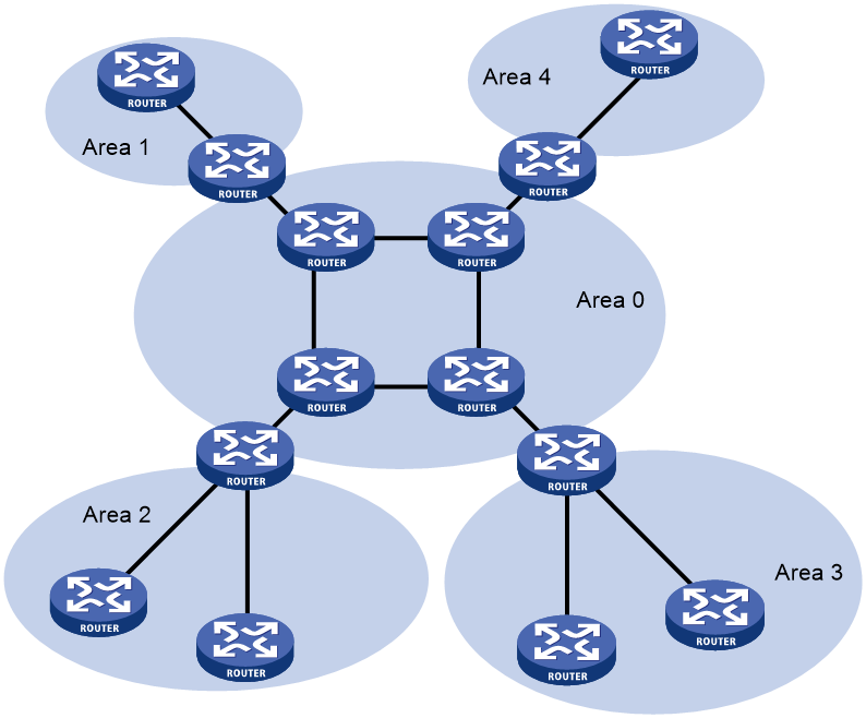
To resolve these issues, OSPF splits an AS into multiple areas. Each area is identified by an area ID. The boundaries between areas are routers rather than links. A network segment (or a link) can only reside in one area as shown in Figure 1.
You can configure route summarization on ABRs to reduce the number of LSAs advertised to other areas and minimize the effect of topology changes.
Figure 1 Area-based OSPF network partition
Backbone area
Each AS has a backbone area that distributes routing information between non-backbone areas. Routing information between non-backbone areas must be forwarded by the backbone area. OSPF has the following requirements:
· All non-backbone areas must maintain connectivity to the backbone area.
· The backbone area must maintain connectivity within itself.
In practice, these requirements might not be met due to lack of physical links. OSPF virtual links can solve this issue.
Virtual links
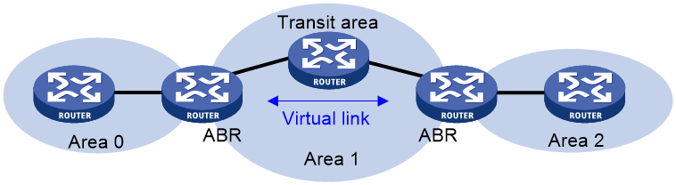
A virtual link is established between two ABRs through a non-backbone area. It must be configured on both ABRs to take effect. The non-backbone area is called a transit area.
As shown in Figure 2, Area 2 has no direct physical link to the backbone Area 0. You can configure a virtual link between the two ABRs to connect Area 2 to the backbone area.
Figure 2 Virtual link application 1
Virtual links can also be used as redundant links. If a physical link failure breaks the internal connectivity of the backbone area, you can configure a virtual link to replace the failed physical link, as shown in Figure 3.
Figure 3 Virtual link application 2
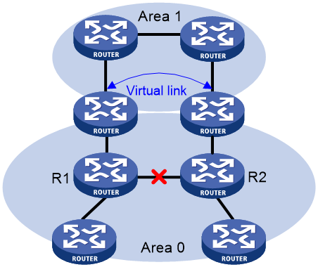
The virtual link between the two ABRs acts as a point-to-point connection. You can configure interface parameters, such as hello interval, on the virtual link as they are configured on a physical interface.
The two ABRs on the virtual link unicast OSPF packets to each other, and the OSPF routers in between convey these OSPF packets as normal IP packets.
Stub area and totally stub area
A stub area does not distribute Type-5 LSAs to reduce the routing table size and LSAs advertised within the area. The ABR of the stub area advertises a default route in a Type-3 LSA so that the routers in the area can reach external networks through the default route.
To further reduce the routing table size and advertised LSAs, you can configure the stub area as a totally stub area. The ABR of a totally stub area does not advertise inter-area routes or external routes. It advertises a default route in a Type-3 LSA so that the routers in the area can reach external networks through the default route.
NSSA area and totally NSSA area
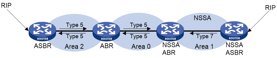
An NSSA area does not import AS external LSAs (Type-5 LSAs) but can import Type-7 LSAs generated by the NSSA ASBR. The NSSA ABR translates Type-7 LSAs into Type-5 LSAs and advertises the Type-5 LSAs to other areas.
As shown in Figure 4, the OSPF AS contains Area 1, Area 2, and Area 0. The other two ASs run RIP. Area 1 is an NSSA area where the ASBR redistributes RIP routes in Type-7 LSAs into Area 1. Upon receiving the Type-7 LSAs, the NSSA ABR translates them to Type-5 LSAs, and advertises the Type-5 LSAs to Area 0.
The ASBR of Area 2 redistributes RIP routes in Type-5 LSAs into the OSPF routing domain. However, Area 1 does not receive Type-5 LSAs because it is an NSSA area.
Router types
As shown in Figure 5, OSPF routers are classified into different types, including internal routers, ABRs, backbone routers, and ASBRs.
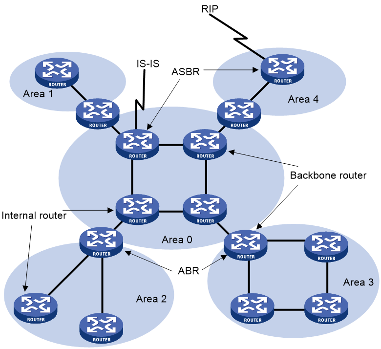
Internal router
All interfaces on an internal router belong to one OSPF area.
ABR
An ABR belongs to more than two areas, one of which must be the backbone area. ABR connects the backbone area to a non-backbone area. An ABR and the backbone area can be connected through a physical or logical link.
Backbone router
No less than one interface of a backbone router must reside in the backbone area. All ABRs and internal routers in Area 0 are backbone routers.
ASBR
An ASBR exchanges routing information with another AS. An ASBR might not reside on the border of the AS. It can be an internal router or an ABR.
Route types
OSPF prioritizes routes into the following route levels:
· Intra-area route.
· Inter-area route.
· Type-1 external route.
· Type-2 external route.
The intra-area and inter-area routes describe the network topology of the AS. The external routes describe routes to external ASs.
A Type-1 external route has high credibility. The cost of a Type-1 external route = the cost from the router to the corresponding ASBR + the cost from the ASBR to the destination of the external route.
A Type-2 external route has low credibility. OSPF considers that the cost from the ASBR to the destination of a Type-2 external route is much greater than the cost from the ASBR to an OSPF internal router. The cost of a Type-2 external route = the cost from the ASBR to the destination of the Type-2 external route. If two Type-2 routes to the same destination have the same cost, OSPF takes the cost from the router to the ASBR into consideration to determine the best route.
Router ID
A router ID uniquely identifies a router in an AS. For a router to run OSPF, it must have a router ID. You can choose to manually specify a router ID or use the global router ID for an OSPF process.
Manual configuration
When you create an OSPF process, you can manually specify a router ID. To make sure the router ID is unique in the AS, you can specify the IP address of an interface on the router as the router ID.
Autoconfiguration
When you create an OSPF process, you can enable the OSPF process to automatically obtain a router ID. The OSPF process obtains a router ID in the following ways:
· During the startup of the OSPF process, the primary IPv4 address of the first interface that runs the process is specified as the router ID.
· During the reboot of the router, the primary IPv4 address of the first interface that runs the process is specified as the router ID.
· During the restart of the OSPF process, the highest primary IPv4 address of the loopback interface that runs the process is specified as the router ID. If no loopback address is available, the highest primary IPv4 address of the interface that runs the process is used, regardless of the interface state (up or down).
Using the global router ID
If you do not specify a router ID when creating an OSPF process, the global router ID is used. As a best practice, manually specify a router ID or enable the OSPF process to automatically obtain a router ID when you create the OSPF process.
Route calculation
OSPF computes routes in an area as follows:
· Each router generates LSAs based on the network topology around itself, and sends them to other routers in update packets.
· Each OSPF router collects LSAs from other routers to compose an LSDB. An LSA describes the network topology around a router, and the LSDB describes the entire network topology of the area.
· Each router transforms the LSDB to a weighted directed graph that shows the topology of the area. All the routers within the area have the same graph.
· Each router uses the SPF algorithm to compute a shortest path tree that shows the routes to the nodes in the area. The router itself is the root of the tree.
OSPF network types
OSPF classifies networks into the following types, depending on different link layer protocols:
· Broadcast—If the link layer protocol is Ethernet or FDDI, OSPF considers the network type as broadcast by default. On a broadcast network, hello, LSU, and LSAck packets are multicast to 224.0.0.5 that identifies all OSPF routers or to 224.0.0.6 that identifies the DR and BDR. DD packets and LSR packets are unicast.
· NBMA—If the link layer protocol is Frame Relay, ATM, or X.25, OSPF considers the network type as NBMA by default. OSPF packets are unicast on an NBMA network.
· P2MP—No link is P2MP type by default. P2MP must be a conversion from other network types such as NBMA. On a P2MP network, OSPF packets are multicast to 224.0.0.5.
· P2P—If the link layer protocol is PPP or HDLC, OSPF considers the network type as P2P. On a P2P network, DD packets are unicast and other OSPF packets are multicast to 224.0.0.5 by default.
The following are the differences between NBMA and P2MP networks:
· NBMA networks are fully meshed. P2MP networks are not required to be fully meshed.
· NBMA networks require DR and BDR election. P2MP networks do not have DR or BDR.
· On an NBMA network, OSPF packets are unicast, and neighbors are manually configured. On a P2MP network, OSPF packets are multicast by default, and you can configure OSPF to unicast protocol packets.
DR and BDR
DR and BDR mechanism
On a broadcast or NBMA network, any two routers must establish an adjacency to exchange routing information with each other. If n routers are present on the network, n(n-1)/2 adjacencies are established. Any topology change on the network results in an increase in traffic for route synchronization, which consumes a large amount of system and bandwidth resources.
Using the DR and BDR mechanisms can solve this problem.
· DR—Elected to advertise routing information among other routers. If the DR fails, routers on the network must elect another DR and synchronize information with the new DR. Using this mechanism without BDR is time-consuming and is prone to route calculation errors.
· BDR—Elected along with the DR to establish adjacencies with all other routers. If the DR fails, the BDR immediately becomes the new DR, and other routers elect a new BDR.
Routers other than the DR and BDR are called DR Others. They do not establish adjacencies with one another, so the number of adjacencies is reduced.
The role of a router is subnet (or interface) specific. It might be a DR on one interface and a BDR or DR Other on another interface.
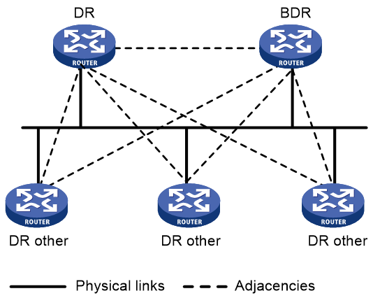
As shown in Figure 6, solid lines are Ethernet physical links, and dashed lines represent OSPF adjacencies. With the DR and BDR, only seven adjacencies are established.
Figure 6 DR and BDR in a network
|
|
NOTE: In OSPF, neighbor and adjacency are different concepts. After startup, OSPF sends a hello packet on each OSPF interface. A receiving router checks parameters in the packet. If the parameters match its own, the receiving router considers the sending router an OSPF neighbor. Two OSPF neighbors establish an adjacency relationship after they synchronize their LSDBs through exchange of DD packets and LSAs. |
DR and BDR election
DR election is performed on broadcast or NBMA networks but not on P2P and P2MP networks.
Routers in a broadcast or NBMA network elect the DR and BDR by router priority and ID. Routers with a router priority value higher than 0 are candidates for DR and BDR election.
The election votes are hello packets. Each router sends the DR elected by itself in a hello packet to all the other routers. If two routers on the network declare themselves as the DR, the router with the higher router priority wins. If router priorities are the same, the router with the higher router ID wins.
If a router with a higher router priority becomes active after DR and BDR election, the router cannot replace the DR or BDR until a new election is performed. Therefore, the DR of a network might not be the router with the highest priority, and the BDR might not be the router with the second highest priority.
OSPF state machines
Interface state machine
On receipt of link state information, OSPF establishes adjacency relationships with neighboring devices, and then exchanges LSAs with them. The state of an OSPF interface indicates the role of the device in an OSPF link. Two neighboring devices can correctly form an adjacency relationship by checking each other's interface state.
The interface state machine involves the following interface states:
· Down—Initial interface state.
An OSPF interface in this state cannot be used for traffic sending or receiving.
· Loopback—The network-attached interface is looped back on the device.
A loopback interface is not available for regular data transmission. However, to obtain link quality information on the interface, you might either send ICMP ping packets to the loopback interface or have a bit error test. To meet this potential requirement, each OSPF device advertises loopback interface information in Router LSAs.
· Waiting—The device is determining the DR and BDR for the network.
When the device does not run for the DR or BDR, the interface starts a wait timer. The hello packets sent by the device does not contain any DR or BDR information unless the wait timer expires. The device cannot be elected as the DR or BDR on the network until it exits from Waiting state. The wait timer mechanism prevents unnecessary DR and BDR changes.
This interface state is supported only on NBMA networks and broadcast networks.
· Point-to-point—The interface is connected to a physical P2P network or to a virtual link.
If an interface enters this state, it attempts to establish an adjacency relationship with the neighboring device.
This interface state is supported only on P2P networks and P2MP networks.
· DR Other—The interface is connected to a broadcast or NBMA network on which another device has been elected as the DR.
A device in DR Other state is neither elected as the DR nor the BDR. When DR and BDR election is complete on the network, each DR Other device establishes adjacencies with both the DR and the BDR.
· BDR—The device is the BDR on the attached network.
As the BDR, the device establishes adjacencies with all other devices on the attached network. It will immediately become the new DR if the existing DR fails.
· DR—The device is the DR on the attached network.
As the DR, the device establishes adjacencies with all other devices on the attached network.
A number of input events (IE) can cause OSPF interface state changes. As shown in Figure 7, the relationships between IEs and state changes form the OSPF interface state machine.
Figure 7 OSPF interface state machine
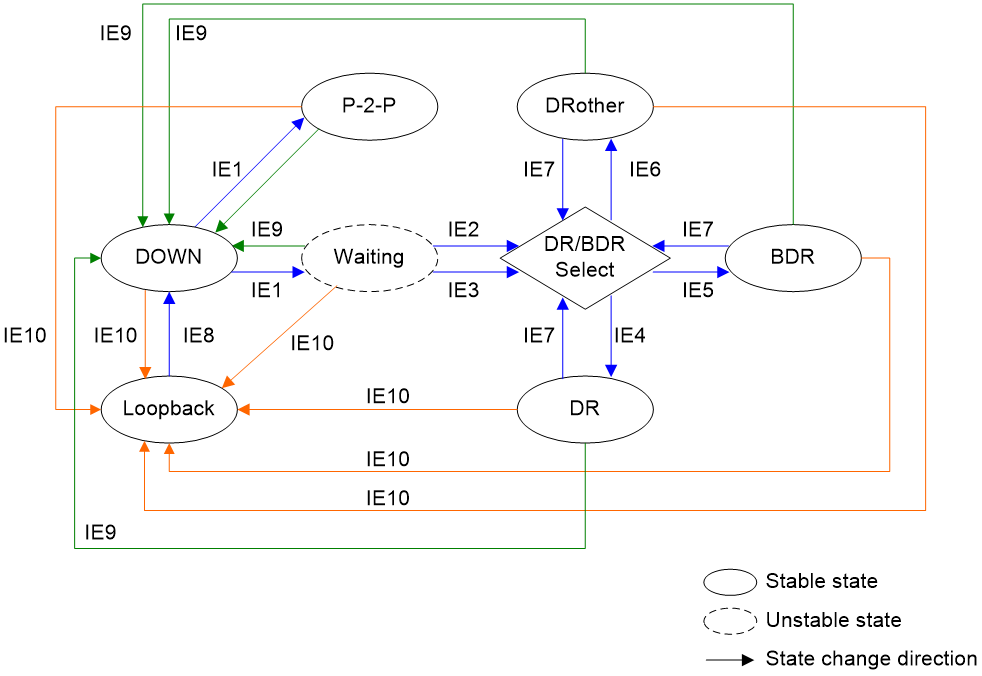
Table 1 shows the IEs that can cause interface state changes.
|
Input event |
Description |
|
IE1 |
InterfaceUp event: Lower-level protocols have indicated that the interface is operational. |
|
IE2 |
WaitTimer event: The wait timer has expired and the device can run for the DR or the BDR. |
|
IE3 |
BackupSeen event: The device has detected the existence or non-existence of a BDR on the attached network through one of the following methods: · The interface receives a hello packet from a neighbor that claims itself to be the BDR. · The interface receives a hello packet from a neighbor that claims itself to be the DR. The hello packet also indicates that there is no BDR. This event marks an end to Waiting state and indicates that the device and the neighbor can have bidirectional communication. |
|
IE4 |
The interface is elected as the DR. |
|
IE5 |
The interface is elected as the BDR. |
|
IE6 |
The interface is neither elected as the DR nor the BDR. |
|
IE7 |
NeighborChange event: A neighbor associated with the interface has a change. The DR and BDR need to be re-elected. The following neighbor changes might lead to the re-election of DR and BDR: · The device can have bidirectional communication with a neighbor. · The device no longer has bidirectional communication with a neighbor. · A neighbor claims itself as DR or BDR. The device detects this event again by examining the hello packets from the neighbor. · A neighbor no longer claims itself as DR or BDR. The device detects this event again by examining the hello packets from the neighbor. · The DR priority for a neighbor has changed. The device detects this event again by examining the hello packets from the neighbor. |
|
IE8 |
UnloopInd event: Network management or lower-level protocols has indicated that the interface is no longer looped back. |
|
IE9 |
InterfaceDown event: Lower-level protocols has indicated that the interface is not operational. If this event occurs, the interface state might change to Down. |
|
IE10 |
LoopInd event: Network management or lower-level protocols has indicated that the interface is looped back. If this event occurs, the interface state might change to Loopback. |
Neighbor state machine
The process of OSPF adjacency establishment involves a series of neighbor state changes that transition from Down state to Full state.
The neighbor state machine involves the following neighbor states:
· Down—Initial state of a neighbor conversation.
This state indicates that the local device does not receive any hello packets from the neighbor within the neighbor dead interval. An OSPF device sends hello packets at intervals of PollInterval.
Whether an OSPF device sends hello packets to neighbors in Down state depends on its network type. The device sends hello packets to neighbors in Down state only when its network type is NBMA.
· Attempt—In this state, the local device attempts to establish neighbor relationships with the manually specified neighbors by sending hello packets at intervals of HelloInterval.
This state is valid only for the neighbors on NBMA networks.
· Init—This state indicates that the local device has received a hello packet from a neighbor before the neighbor dead interval elapses. However, the local device has not established bidirectional communication with the neighbor, because the received hello packet does not contain the local device's router ID.
· 2-Way—This state indicates that the local device has established a neighbor relationship with a neighboring device. Each of the two devices has received a hello packet from another and has seen its own router ID in the received hello packet.
If the neighbor relationship between two devices does not prompt to an adjacency, the neighbor state will remain 2-Way.
DR and BDR election starts only when the neighbor state is 2-Way or greater.
· ExStart—This state indicates that the local device and the neighbor is deciding which is the master. This step is to determine the sequence number for initial DD packets. The devices can then exchange DD packets in order.
· Exchange—This state indicates that the local device is exchanging DD packets with the neighbor. The local device describes its LSDB information in DD packets and sends them to the neighbor.
· Loading—This state indicates that the local device and the neighbor are having bidirectional LSDB synchronization. They send LSRs to each other to request the most recent LSAs, and then synchronize their LSDBs through exchanges of LSUs and LSAcks.
· Full—This state indicates that the local device and the neighbor has completed bidirectional LSDB synchronization and they are fully adjacent.
As shown in Figure 8, the relationships between IEs and state changes form the OSPF neighbor state machine.
Figure 8 OSPF neighbor state machine
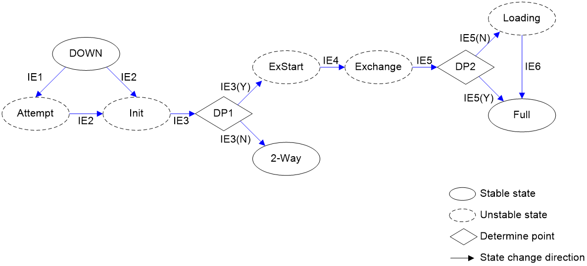
Table 2 shows the IEs that can cause neighbor state changes.
|
Input event |
Description |
|
IE1 |
Start event: The OSPF device attempts to establish a neighbor relationship with the neighbor by sending hello packets at intervals of HelloInterval. This event is supported only on NBMA networks. |
|
IE2 |
HelloReceived event: The OSPF device has received a hello packet from the neighbor. |
|
IE3 |
2-WayReceived event: The OSPF device has received a hello packet from the neighbor and has seen its router ID in the received hello packet. The two neighboring devices have established bidirectional communication. The OSPF device then performs the following task: · If the OSPF device needs to form an adjacency with the neighbor, it changes the neighbor state to ExStart. · If the OSPF device should not form an adjacency with the neighbor, it changes the neighbor state to 2-Way. |
|
IE4 |
NegotiationDone event: The OSPF device and the neighbor have completed master/secondary relationship negotiation and have determined the sequence number for initial DD packets. |
|
IE5 |
ExchangeDone event: The OSPF device have exchanged DD packets with the neighbor. The OSPF device then performs the following task: · If the LSR list is empty, the device changes the neighbor state to Full. This neighbor state indicates that bidirectional LSDB synchronization is complete and the device has established an adjacency with the neighbor. · If the LSR list is not empty, the device changes the neighbor state to Loading, and then sends LSRs to the neighbor to request missing link state information. |
|
IE6 |
LoadingDone event: The LSR list is already empty. |
Protocols and standards
· RFC 1245, OSPF protocol analysis
· RFC 1246, Experience with the OSPF protocol
· RFC 1370, Applicability Statement for OSPF
· RFC 1403, BGP OSPF Interaction
· RFC 1745, BGP4/IDRP for IP---OSPF Interaction
· RFC 1765, OSPF Database Overflow
· RFC 1793, Extending OSPF to Support Demand Circuits
· RFC 2154, OSPF with Digital Signatures
· RFC 2328, OSPF Version 2
· RFC 3101, OSPF Not-So-Stubby Area (NSSA) Option
· RFC 3166, Request to Move RFC 1403 to Historic Status
· RFC 3509, Alternative Implementations of OSPF Area Border Routers
· RFC 4167, Graceful OSPF Restart Implementation Report
· RFC 4577, OSPF as the Provider/Customer Edge Protocol for BGP/MPLS IP Virtual Private Networks (VPNs)
· RFC 4750, OSPF Version 2 Management Information Base
· RFC 4811, OSPF Out-of-Band LSDB Resynchronization
· RFC 4812, OSPF Restart Signaling
· RFC 5088, OSPF Protocol Extensions for Path Computation Element (PCE) Discovery
· RFC 5250, The OSPF Opaque LSA Option
· RFC 5613, OSPF Link-Local Signaling
· RFC 5642, Dynamic Hostname Exchange Mechanism for OSPF
· RFC 5709, OSPFv2 HMAC-SHA Cryptographic Authentication
· RFC 5786, Advertising a Router's Local Addresses in OSPF Traffic Engineering (TE) Extensions
· RFC 6571, Loop-Free Alternate (LFA) Applicability in Service Provider (SP) Networks
· RFC 6860, Hiding Transit-Only Networks in OSPF
· RFC 6987, OSPF Stub Router Advertisement
Restrictions and guidelines: OSPF configuration
To run OSPF, you must first enable OSPF on the router. Make a proper configuration plan to avoid incorrect settings that can result in route blocking and routing loops.
Configuring basic OSPF functions
Enabling an OSPF process
system-view
2. (Optional.) Configure a global router ID.
router id router-id
By default, no global router ID is configured.
If no global router ID is configured, the highest loopback interface IP address, if any, is used as the router ID. If no loopback interface IP address is available, the highest physical interface IP address is used, regardless of the interface status (up or down).
3. Enter OSPF view.
ospf [ process-id | router-id { auto-select | router-id } ] *
By default, OSPF is disabled.
4. (Optional.) Configure a description for the OSPF process.
description text
By default, no description is configured for the OSPF process.
As a best practice, configure a description for each OSPF process.
Creating an OSPF area
1. Enter system view.
system-view
2. (Optional.) Configure a global router ID.
router id router-id
By default, no global router ID is configured.
3. Enter OSPF view.
ospf [ process-id | router-id { auto-select | router-id } ] *
By default, OSPF is disabled.
4. (Optional.) Configure a description for the OSPF process.
description text
By default, no description is configured for the OSPF process.
As a best practice, configure a description for each OSPF process.
5. Create an OSPF area and enter OSPF area view.
area area-id
6. (Optional.) Configure a description for the area.
description text
By default, no description is configured for the area.
As a best practice, configure a description for each OSPF area.
Enabling OSPF
About this task
To enable OSPF on a router, you must perform the following tasks:
1. Create an OSPF process.
2. Create an OSPF area for the process.
3. Specify a network in the area.
The interface attached to the network will run the OSPF process in the area. OSPF advertises direct routes of the interface.
OSPF supports multiple processes. To run multiple OSPF processes, you must specify an ID for each process. The process IDs take effect locally and has no influence on packet exchange between routers. Two routers with different process IDs can exchange packets.
Restrictions and guidelines for enabling OSPF
When you configure OSPF on an interface, follow these restrictions and guidelines:
· You can enable OSPF on the network where the interface resides or directly enable OSPF on that interface. If you configure both, the latter takes precedence.
· If the specified OSPF process and area do not exist, the operation creates an OSPF process and area for the interface. Disabling an OSPF process on an interface does not delete the OSPF process or the area.
Enabling OSPF on a network
1. Enter system view.
system-view
2. Enter OSPF view.
ospf [ process-id | router-id { auto-select | router-id } ] *
3. Create an OSPF area and enter OSPF area view.
area area-id
4. Specify a network to enable the interface attached to the network to run the OSPF process in the area.
network ip-address wildcard-mask
By default, no network is specified to enable OSPF on the interface attached to the network.
A network can be added to only one area.
Enabling OSPF on an interface
1. Enter system view.
system-view
2. Enter interface view.
interface interface-type interface-number
3. Enable an OSPF process on the interface.
ospf process-id area area-id [ exclude-subip ]
By default, OSPF is disabled on an interface.
Configuring OSPF dynamic host name mappings
About this task
OSPF uses a router ID to uniquely identify a router in an AS. The length of router IDs is fixed at 4 bytes. It is inconvenient for the network administrator to memorize the router IDs in dotted decimal notation when verifying the OSPF neighbor relationships, routing tables, and LSDBs.
This task allows you to map a router ID to a host name. The mapping table is maintained by OSPF routers. Host names are more straightforward than router IDs in network maintenance, management, and failure diagnosis.
Restrictions and guidelines
OSPF uses Type-10 LSAs and Type-11 LSAs to carry information about the dynamic host name attribute. Therefore, make sure the opaque LSA reception and advertisement capability is enabled.
Procedure
1. Enter system view.
system-view
2. Enable OSPF, and enter OSPF view.
ospf [ process-id | router-id { auto-select | router-id } ] *
3. Enable the opaque LSA reception and advertisement capability.
opaque-capability enable
By default, the opaque LSA reception and advertisement capability is enabled.
4. Enable the OSPF dynamic host name mapping feature.
hostname [ host-name ]
By default, the OSPF dynamic host name mapping feature is disabled.
Display and maintenance commands for OSPF
Execute display commands in any view and reset commands in user view.
|
Task |
Command |
|
Display summary route information on the OSPF ABR. |
display ospf [ process-id ] [ area area-id ] abr-summary [ ip-address { mask-length | mask } ] [ verbose ] |
|
Display OSPF SPF information. |
display ospf [ process-id ] [ area area-id ] spf-tree [ verbose ] |
|
Display OSPF process information. |
display ospf [ process-id ] [ verbose ] |
|
Display OSPF ABR and ASBR information. |
display ospf [ process-id ] abr-asbr [ verbose ] |
|
Display OSPF log information. |
display ospf [ process-id ] event-log { lsa-flush | peer | spf } |
|
Display OSPF log information about received or sent hello packets. |
display ospf [ process-id ] event-log hello { received [ abnormal | dropped ] | sent } [ neighbor-id ] display ospf [ process-id ] event-log hello sent { abnormal | failed } [ neighbor-address ] |
|
Display the router ID-to-host name mapping table. |
display ospf [ process-id ] hostname-table |
|
Display OSPF interface information. |
display ospf [ process-id ] interface [ interface-type interface-number | verbose ] |
|
Display information about hello packets sent by OSPF interfaces. |
display ospf [ process-id ] interface [ interface-type interface-number ] hello |
|
Display OSPF LSDB information. |
display ospf [ process-id ] [ area area-id ] lsdb { asbr | network | nssa | opaque-area | opaque-link | router | summary } [ link-state-id ] [ originate-router advertising-router-id | self-originate ] [ age { max-value max-age-value | min-value min-age-value } * ] [ resolve-hostname ] |
|
Display OSPF next hop information. |
display ospf [ process-id ] nexthop |
|
Display OSPF neighbor information. |
display ospf [ process-id ] peer [ hello | verbose ] [ interface-type interface-number ] [ [ neighbor-id ] [ resolve-hostname ] | hostname host-name ] |
|
Display neighbor statistics for OSPF areas. |
display ospf [ process-id ] peer statistics |
|
Display OSPF request queue information. |
display ospf [ process-id ] request-queue [ interface-type interface-number ] [ neighbor-id ] |
|
Display OSPF retransmission queue information. |
display ospf [ process-id ] retrans-queue [ interface-type interface-number ] [ neighbor-id ] |
|
Display OSPF routing table information. |
display ospf [ process-id ] routing [ ip-address { mask-length | mask } ] [ interface interface-type interface-number ] [ nexthop nexthop-address ] [ verbose ] |
|
Display OSPF statistics. |
display ospf [ process-id ] statistics [ error | packet [ hello | interface-type interface-number ] ] |
|
Display the global router ID. |
display router id |
|
Clear OSPF log information. |
reset ospf [ process-id ] event-log [ lsa-flush | peer | spf ] |
|
Clear OSPF log information about received or sent hello packets. |
reset ospf [ process-id ] event-log hello { received [ abnormal | dropped ] | sent [ abnormal | failed ] } |
|
Restart an OSPF process. |
reset ospf [ process-id ] process |
|
Clear OSPF statistics. |
reset ospf [ process-id ] statistics |
