- Table of Contents
-
- 05-Network Connectivity
- 00-Preface
- 01-About the network connectivity configuration guide
- 02-MAC address table configuration
- 03-VLAN configuration
- 04-Ethernet link aggregation configuration
- 05-Spanning tree configuration
- 06-LLDP configuration
- 07-Layer 2 forwarding configuration
- 08-PPP configuration
- 09-L2TP configuration
- 10-ARP configuration
- 11-IP addressing configuration
- 12-DHCP configuration
- 13-DHCPv6 configuration
- 14-DNS configuration
- 15-NAT configuration
- 16-IP performance optimization configuration
- 17-IPv6 basics configuration
- 18-Tunneling configuration
- 19-GRE configuration
- 20-ADVPN configuration
- 21-IP forwarding basics configuration
- 22-Basic IP routing configuration
- 23-Static routing configuration
- 24-IPv6 static routing configuration
- 25-Policy-based routing configuration
- 26-IPv6 policy-based routing configuration
- 27-RIP configuration
- 28-OSPF configuration
- 29-RIPng configuration
- 30-BGP configuration
- 31-Multicast overview
- 32-IGMP snooping configuration
- 33-MLD snooping configuration
- Related Documents
-
| Title | Size | Download |
|---|---|---|
| 08-PPP configuration | 589.89 KB |
PPP link establishment process
Restoring the default settings for the VT interface
Configuring PPP authentication
Configuring PAP authentication
Configuring CHAP authentication (authenticator name is configured)
Configuring CHAP authentication (authenticator name is not configured)
Configuring the polling feature
Configuring the PPP negotiation timeout time
Configuring IP address negotiation on the client
Configuring IP address negotiation on the server
Configuring DNS server IP address negotiation on the client
Configuring DNS server IP address negotiation on the server
Enabling IP header compression
Configuring the NAS-Port-Type attribute
Display and maintenance commands for PPP
Interaction process for PPPoE user onboarding
PPPoE MTU and MRU negotiation method
Restrictions and guidelines for PPPoE
PPPoE server tasks at a glance
Enabling the function of querying and configuring VA interfaces through MIB nodes
Setting the maximum number of PPPoE sessions
Limiting the PPPoE access rate
Configuring the NAS-Port-ID attribute
PPPoE client tasks at a glance
Configuring a dialer interface
Display and maintenance commands for PPPoE
Display and maintenance commands for PPPoE server
Display and maintenance commands for PPPoE client
Example: Configuring a PPPoE client in permanent mode
Example: Configuring a PPPoE client in on-demand mode
Example: Configuring a PPPoE client in diagnostic mode
Configuring PPP
About PPP
Point-to-Point Protocol (PPP) is a point-to-point link layer protocol. It provides user authentication, supports synchronous/asynchronous communication, and allows for easy extension.
PPP protocols
PPP includes the following protocols:
· Link control protocol (LCP)—Establishes, tears down, and monitors data links.
· Network control protocol (NCP)—Negotiates the packet format and type for data links.
· Authentication protocols—Authenticate users. Protocols include the following:
¡ Password Authentication Protocol (PAP).
¡ Challenge Handshake Authentication Protocol (CHAP).
Basic concepts of PPP
Basic architecture of PPP
The PPP protocol is in the data link layer of TCP/IP. It is mainly used to support full-duplex synchronous and asynchronous links for point-to-point data transmission.
Figure 1 Position of PPP in the protocol stack
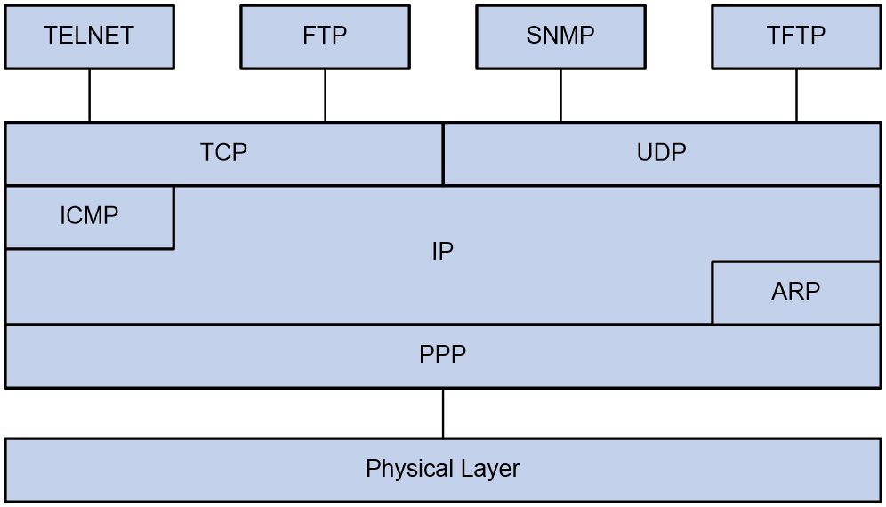
PPP mainly contains the following protocol families:
· Link Control Protocol (LCP) family—Mainly used to establish, terminate, and monitor a PPP data link.
· Network Control Protocol (NCP) family—Mainly used to negotiate the format and type of data packets transmitted on a data link.
· PPP extension protocol family—Mainly used to provide further support for PPP functionality. For example, PPP provides authentication protocols CHAP and PAP for network security.
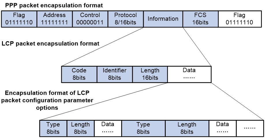
Frame format of PPP packet encapsulation
The PPP packet encapsulation format is as shown in Figure 2.
The fields are described as follows:
· Flag field
The flag field identifies the start and end of a physical frame, and this byte is 0x7E.
· Address field
The address field can uniquely identify the peer end. The PPP protocol is used on point-to-point links, so two communicating devices interconnected by using the PPP protocol do not need to know each other's data link layer address. According to the protocol, the byte is filled with the all-1 broadcast address, which has no practical meaning for the PPP protocol.
· Control field
The default value for this field is 0x03, indicating unnumbered frame. By default, PPP does not use sequence numbers and acknowledgment mechanism to achieve reliable transmission.
The address and control fields together identify this packet as a PPP packet. Therefore, the PPP packet header is FF03.
· Protocol field
The protocol field distinguishes the packet types carried in the information field of PPP frames.
The contents of the protocol field must conform to the provisions of the address extension mechanism provided by ISO 3309. The mechanism specifies that the contents filled in the protocol field must be odd, which means the lowest significant bit in the lowest significant byte should be 1 and the lowest significant bit in the highest significant byte should be 0.
If the protocol field of the PPP frame sent by the sender does not meet the preceding requirements, the receiver will consider this frame unrecognizable. The receiver sends a Protocol-Reject packet to the sender, including the rejected protocol number at the end of the packet.
Table 1 Common protocol codes
|
Protocol code |
Protocol type |
|
0021 |
Internet Protocol |
|
002b |
Novell IPX |
|
002d |
Van Jacobson Compressed TCP/IP |
|
002f |
Van Jacobson Uncompressed TCP/IP |
|
8021 |
Internet Protocol Control Protocol |
|
802b |
Novell IPX Control Protocol |
|
8031 |
Bridging NC |
|
C021 |
Link Control Protocol |
|
C023 |
Password Authentication Protocol |
|
C223 |
Challenge Handshake Authentication Protocol |
· Information field
The maximum length of the information field is 1500 bytes, including the content of the padding field. The maximum length of the information field is called the Maximum Receive Unit (MRU). The default MRU is 1500 bytes. In actual applications, you can negotiate the MRU as needed.
If the information field length is insufficient, it can be padded, which is not required. If padding is applied, both ends of the communication must be able to distinguish between the padded information and the actual information that needs to be transmitted to communicate properly.
· FCS field
The main purpose of the FCS field is to check the correctness of PPP frame transmission.
Introducing some transmission assurance mechanisms into the frame will introduce more overhead, which might increase the latency of application layer interaction.
Frame format of LCP packet encapsulation
The LCP packet encapsulation format is as shown in Figure 2.
During the link establishment phase, the PPP protocol establishes and negotiates the link through LCP packets. At this time, an LCP packet is encapsulated as the payload of PPP in the information field of the PPP frame, and the protocol field of the PPP frame is padded with a fixed value of 0xC021.
During the entire process of link establishment, the content of the information field is variable, including many types of packets. These packets also need to be distinguished through the corresponding fields.
· Code field
The code field is one byte long and is mainly used to identify the type of LCP data packets.
During the link establishment phase, the receiver receives the LCP data packets. When the value of their code field is invalid, the receiver will send a Code-Reject packet to the peer end.
Table 2 Common code values
|
Code value |
Packet type |
|
0x01 |
Configure-Request |
|
0x02 |
Configure-Ack |
|
0x03 |
Configure-Nak |
|
0x04 |
Configure-Reject |
|
0x05 |
Terminate-Request |
|
0x06 |
Terminate-Ack |
|
0x07 |
Code-Reject |
|
0x08 |
Protocol-Reject |
|
0x09 |
Echo-Request |
|
0x0A |
Echo-Reply |
|
0x0B |
Discard-Request |
|
0x0C |
Reserved |
· Identifier field
The identifier field is 1 byte long, and it is used to match requests and replies. When the identifier field value of a packet is illegal, the packet will be dropped.
Typically, the ID of a Configure-Request packet starts at 0x01 and increases gradually by 1. When the peer end receives the Configure-Request packet, the ID in the response packet must be the same as the ID in the received packet no matter what kind of packet is used to respond.
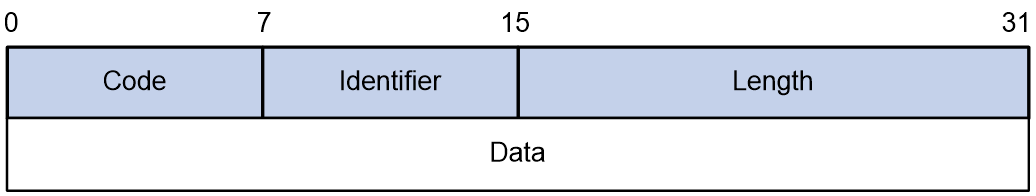
· Length field
The value of the length field is the total number of bytes in the LCP packet. It is the sum of the lengths of the four fields: code, identifier, length, and data fields.
Bytes beyond the number indicated by the length field will be treated as padded bytes and ignored, and the content of the length field cannot exceed the MRU.
· Data field
The data field contains the content of the negotiation packet, including the following fields.
¡ The type field indicates the negotiation option type.
¡ The length field indicates the negotiation option length, which is the total length of the data field, including type, length, and data.
¡ The data field contains details of the negotiation option.
Table 3 Common negotiation type values in the type field
|
Negotiation type value |
Negotiation packet type |
|
0x01 |
Maximum-Receive-Unit |
|
0x02 |
Async-Control-Character-Map |
|
0x03 |
Authentication-Protocol |
|
0x04 |
Quality-Protocol |
|
0x05 |
Magic-Number |
|
0x06 |
RESERVED |
|
0x07 |
Protocol-Field-Compression |
|
0x08 |
Address-and-Control-Field-Compression |
PPP link establishment process
Basic process
Figure 3 shows the PPP link establishment process.
Figure 3 PPP link establishment process
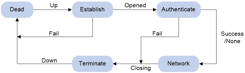
1. Initially, PPP is in Link Dead phase. After the physical layer goes up, PPP enters the Link Establishment phase (Establish).
2. In the Link Establishment phase, the LCP negotiation is performed. The LCP configuration options include Authentication-Protocol, Async-Control-Character-Map (ACCM), Maximum-Receive-Unit (MRU), Magic-Number, Protocol-Field-Compression (PFC), Address-and-Control-Field-Compression (ACFC).
¡ If the negotiation fails, LCP reports a Fail event, and PPP returns to the Dead phase.
¡ If the negotiation succeeds, LCP enters the Opened state and reports an Up event, indicating that the underlying layer link has been established. At this time, the PPP link is not established for the network layer, and network layer packets cannot be transmitted over the link.
3. If authentication is configured, the PPP link enters the Authentication phase, where PAP, CHAP, MS-CHAP, or MS-CHAP-V2 authentication is performed.
¡ If the client fails to pass the authentication, LCP reports a Fail event and enters the Link Termination phase. In this phase, the link is torn down and LCP goes down.
¡ If the client passes the authentication, LCP reports a Success event.
4. If a network layer protocol is configured, the PPP link enters the Network-Layer Protocol phase for NCP negotiation, such as IPCP negotiation and IPv6CP negotiation.
¡ If the NCP negotiation succeeds, the link goes up and becomes ready to carry negotiated network-layer protocol packets.
¡ If the NCP negotiation fails, NCP reports a Down event and enters the Link Termination phase.
If the interface is configured with an IP address, the IPCP negotiation is performed. IPCP configuration options include IP addresses and DNS server IP addresses. After the IPCP negotiation succeeds, the link can carry IP packets.
5. After the NCP negotiation is performed, the PPP link remains active until either of the following events occurs:
¡ Explicit LCP or NCP frames close the link.
¡ Some external events take place (for example, the intervention of a user).
Dead phase (physical-layer not ready phase)
The dead phase is also known as the physical-layer not ready phase. A PPP link necessarily begins and ends with this phase.
When both ends of the communication detect the physical line activation (usually the carrier signal on the link), they will transition from the dead phase to link establishment phase.
The link will return to the physical-layer not ready phase after it is disconnected.
Establish phase (link establishment phase)
During the establish phase, a PPP link undergoes LCP negotiation. The negotiation content includes options such as single-link PPP (SP) or multilink PPP (MP), maximum receive unit (MRU), authentication method, and magic number. When the exchange of configuration packets is completed, the link will proceed to the next phase.
|
|
NOTE: After the link is established, the next phase can be selected based on the configuration of the devices at both ends of the link. The next phase can be either the authentication phase or the network layer protocol phase. This selection depends on the configuration made by the user on the devices at both ends of the link. |
During the establish phase, the LCP state machine will undergo the following changes.
· When the link is in physical-layer not ready phase, the LCP state machine is in the Initial or Starting state. When the physical layer detects that the link is available, it will send an Up event to the link layer. Upon receiving this event, the link layer will change the LCP state machine from the current state to Request-Sent state. Then, LCP will take corresponding actions to send a Configure-Request packet to configure the data link.
· If the local device receives the Configure-Ack packet first, the LCP state machine will change from Request-Sent state to Ack-Received state. After the local end sends the Configure-Ack packet to the peer end, the LCP state machine will change from Ack-Received state to Open state.
· If the local device sends a Configure-Ack packet to the peer end first, the LCP state machine will change from Request-Sent state to Ack-Sent state. After the local end receives the Configure-Ack packet from the peer end, the LCP state machine will change from Ack-Sent state to Open state.
· Once the LCP state machine enters Open state, the link completes the current negotiation phase and proceeds to the next phase.
Authenticate phase (authentication phase)
By default, a PPP link does not perform authentication. If authentication is required, the authentication protocol must be specified during the link establishment phase.
PPP provides two authentication methods: Password Authentication Protocol (PAP) and Challenge Handshake Authentication Protocol (CHAP).
|
|
NOTE: PPP authentication methods include one-way authentication and two-way authentication. · One-way authentication refers to one end acting as the authenticator and the other end as the authenticatee. · Two-way authentication is a simple overlay of one-way authentication, where both ends act as both the authenticator and the authenticatee. |
PAP authentication process
PAP authentication is two-way handshake authentication, and uses simple passwords.
The process of PAP authentication is shown in Figure 4.
Figure 4 PAP authentication process

1. The authenticatee sends the local username and password to the authenticator.
2. The authenticator checks the local user table to identify whether the authenticatee's username exists.
¡ If yes, the authenticator identifies whether the password is correct.
- If the password is correct, the authentication will succeed.
- If the password is incorrect, the authentication will fail.
¡ If not, the authentication will fail.
Frame format of a PAP authentication packet
A PAP packet is encapsulated with a protocol field of 0xC023 in the information field of the PPP data link layer frame. The frame format of a PAP packet is as shown in Figure 5.
Figure 5 Frame format of a PAP authentication packet
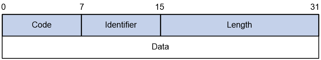
In the frame format of a PAP authentication packet, the meaning of each field is described in Table 4.
Table 4 Fields in the frame format of a PAP authentication packet
|
Field |
Length (bytes) |
|
Code |
1 |
|
Identifier |
1 |
|
Length |
2 |
|
Data |
0 or more bytes |
CHAP authentication process
CHAP authentication is a three-way handshake authentication protocol. CHAP transmits only the username rather than the user password over the network, so it is more secure than PAP.
The authentication process of CHAP is as shown in Figure 6.
Figure 6 CHAP authentication process

The CHAP one-way authentication process supports two cases: the authenticator has configured a username and the authenticator has not configured a username. As a best practice, use the method of configuring the username on the authenticator, so that the username of the authenticator can be confirmed.
· Authentication process when the authenticator has configured a username
a. The authenticator initiates the authentication request, constructs a packet containing a random number, and at the same time sends the local username to the authenticatee. (Challenge.)
b. When the authenticatee receives the authentication request from the authenticator, the authenticatee first identifies whether a CHAP password is configured on the local interface.
- If the interface is configured with a CHAP password, the authenticatee uses the hash algorithm to calculate a hash value based on the packet ID, CHAP password, and random number in the packet. Then, the authenticatee sends the obtained hash value and the username of the authenticatee back to the authenticator. (Response.)
- If the interface is not configured with a CHAP password, the authenticatee searches for the password corresponding to the user in the local user table based on the authenticator username in the packet. The authenticatee uses the hash algorithm to calculate a hash value based on the packet ID, user password, and the random number in the packet, and sends the obtained hash value and the username of the authenticatee back to the authenticator. (Response).
c. The authenticator first looks up the password corresponding to the user in the local end based on the username of the authenticatee in the received packet. Then, the authenticator uses the hash algorithm to calculate a hash value based on the packet ID, the password of the authenticatee, and the random number in the Challenge packet, and compares the obtained hash value with the hash value in the Response packet. If the comparison result is consistent, the authentication succeeds. If the comparison result is inconsistent, the authentication fails.
· Authentication process when the authenticator has not configured a username
d. The authenticator initiates an authentication request, and sends a packet containing a random number to the authenticatee. (Challenge.)
e. After receiving the authentication request from the authenticator, the authenticatee uses the hash algorithm to calculate a hash value based on the packet ID, configured CHAP password, and random number in the packet. Then, the authenticatee sends the obtained hash value and its own username back to the authenticator. (Response).
f. The authenticator first looks up the password corresponding to the username of the authenticatee in the local send based on the received packet. Then, the authenticator calculates the hash value by using a hash algorithm based on the packet ID, the password of the authenticatee, and the random number in the packet, and compares it with the hash value in the Response packet. If the comparison result is consistent, the authentication succeeds. If the comparison result is inconsistent, the authentication fails.
Frame format of a CHAP authentication packet
A CHAP packet is encapsulated with a protocol field of 0xC223 in the information field of the PPP data link layer frame. The frame format of a CHAP packet is as shown in Figure 7.
Figure 7 Frame format of a CHAP authentication packet
In the frame format of a CHAP authentication packet, the meaning of each field is described in Table 5.
Table 5 Fields in the frame format of a CHAP authentication packet
|
Field |
Length (bytes) |
|
Code |
1 |
|
Identifier |
1 |
|
Length |
2 |
|
Data |
0 or more bytes |
|
|
NOTE: The differences between CHAP and PAP authentication methods are as follows: · PAP authentication involves sending a simple password on the link. After the PPP link is established, the authenticatee continuously sends the username and password on the link until the authentication process ends. Therefore, PAP authentication is not very secure. When the security requirements are not high in practical applications, you can use PAP authentication to establish a PPP connection. · In CHAP authentication, the authentication protocol is a three-way handshake authentication protocol. CHAP transmits only the username rather than the user password over the network, so it is more secure than PAP. When the security requirements are high in practical applications, you can use CHAP authentication to establish a PPP connection. |
Network phase (network layer protocol phase)
After PPP completes the previous phase, PPP selects and configures a network layer protocol and negotiates network layer parameters through NCP negotiation. Each NCP protocol can be enabled and disabled at any time. When the state machine of an NCP protocol becomes Open, PPP can begin network layer data transmission on the link.
Terminate phase (link termination phase)
PPP can terminate the link at any time. When the carrier is lost, authentication fails, or the administrator manually closes the link, the link will be terminated.
PPP authentication
PPP supports the following authentication methods:
PAP
PAP is a two-way handshake authentication protocol using the username and password.
PAP sends username/password pairs in plain text over the network. If authentication packets are intercepted in transit, network security might be threatened. For this reason, it is suitable only for low-security environments.
CHAP
CHAP is a three-way handshake authentication protocol.
CHAP transmits usernames but not passwords over the network. It transmits the result calculated from the password and random packet ID by using the MD5 algorithm. It is more secure than PAP. The authenticator may or may not be configured with a username. As a best practice, configure a username for the authenticator, which makes it easier for the peer to verify the identity of the authenticator.
PPP for IPv4
On IPv4 networks, PPP negotiates the IP address and DNS server address during IPCP negotiation.
IP address negotiation
IP address negotiation enables one end to assign an IP address to the other.
An interface can act as a client or a server during IP address negotiation:
· Client—Obtains an IP address from the server. Use the client mode when the device accesses the Internet through an ISP.
· Server—Assigns an IP address to the client. Before you configure the IP address of the server, you must perform one of the following tasks:
¡ Configure a local address pool and associate the pool with the ISP domain.
¡ Specify an IP address or an address pool for the client on the interface.
When IP address negotiation is enabled on a client, the server selects an IP address for the client in the following sequence:
1. If the AAA server configures an IP address or address pool for the client, the server selects that IP address or an IP address from the pool. The IP address or address pool is configured on the AAA server instead of the PPP server. For information about AAA, see User Access and Authentication Configuration Guide.
2. If an address pool is associated with the ISP domain used during client authentication, the server selects an IP address from the pool.
3. If an IP address or address pool is specified for the client on the interface of the server, the server selects that IP address or an IP address from that pool.
DNS server address negotiation
IPCP negotiation can determine the DNS server IP address.
When the device is connected to a host, configure the device as the server to assign the DNS server IP address to the host.
When the device is connected to an ISP access server, configure the device as the client. Then, the device can obtain the DNS server IP address from the ISP access server.
PPP for IPv6
On IPv6 networks, PPP negotiates only the IPv6 interface identifier instead of the IPv6 address and IPv6 DNS server address during IPv6CP negotiation.
IPv6 address assignment
PPP cannot negotiate the IPv6 address.
The client can get an IPv6 global unicast address through the following methods:
· NDRA—The client obtains an IPv6 prefix in an RA message. The client then generates an IPv6 global unicast address by combining the IPv6 prefix and the negotiated IPv6 interface identifier. The IPv6 prefix in the RA message is determined in the following sequence:
¡ IPv6 prefix authorized by AAA.
¡ RA prefix configured on the interface.
¡ Prefix of the IPv6 global unicast address configured on the interface.
For information about the ND protocol, see Network Connectivity Configuration Guide.
· DHCPv6 (IA_NA)—The client requests an IPv6 global unicast address through DHCPv6. The server assigns an IPv6 address to the client from the address pool authorized by AAA. If no AAA-authorized address pool exists, DHCPv6 uses the address pool that matches the server's IPv6 address to assign an IPv6 address to the client. For information about DHCPv6, see Network Connectivity Configuration Guide.
· DHCPv6 (IA_PD)—The client requests prefixes through DHCPv6 and assigns them to downstream hosts. The hosts then use the prefixes to generate global IPv6 addresses. This method uses the same principle of selecting address pools as DHCPv6 (IA_NA).
The device can assign a host an IPv6 address in either of the following ways:
· When the host connects to the device directly or through a bridge device, the device can use NDRA or DHCPv6 (IA_NA).
· When the host accesses the device through a router, the device can use DHCPv6 (IA_PD) to assign an IPv6 prefix to the router. The router assigns the prefix to the host to generate an IPv6 global unicast address.
· You can use the NDRA+IA_PD combination or the IA_NA+IA_PD combination as needed to meet address assignment requirements in different scenarios.
IPv6 DNS server address assignment
On IPv6 networks, two methods are available for the IPv6 DNS address assignment:
· AAA authorizes the IPv6 DNS address and assigns this address to the host through RA messages.
· The DHCPv6 client requests an IPv6 DNS address from the DHCPv6 server.
Protocols and standards
RFC 1661: The Point-to-Point Protocol (PPP)
PPP tasks at a glance
To configure PPP, perform the following tasks:
Perform this task in PPPoE and L2TP networks.
¡ (Optional.) Restoring the default settings for the VT interface
2. Configuring PPP authentication
Choose one of the following tasks:
¡ Configuring PAP authentication
¡ Configuring CHAP authentication (authenticator name is configured)
¡ Configuring CHAP authentication (authenticator name is not configured)
Configure PPP authentication for high-security environments.
3. (Optional.) Configuring the polling feature
4. (Optional.) Configuring PPP negotiation
¡ Configuring the PPP negotiation timeout time
¡ Configuring IP address negotiation on the client
¡ Configuring IP address negotiation on the server
¡ Configuring DNS server IP address negotiation on the client
¡ Configuring DNS server IP address negotiation on the server
5. (Optional.) Enabling IP header compression
IPHC is often used for voice communications over low-speed links.
6. (Optional.) Configuring the NAS-Port-Type attribute
7. (Optional.) Enabling PPP accounting
8. (Optional.) Enabling PPP user logging
Configuring a VT interface
Creating a VT interface
About this task
A virtual-template (VT) interface is a template for creating VA interfaces. In PPPoE and L2TP networks, VA interfaces are needed for exchanging data with peers. In this case, the system will select a VT interface and dynamically create VA interfaces based on the VT interface.
In PPPoE and L2TP applications, you can use VT interfaces to implement related functions of PPP. For more information about PPPoE and L2TP, see "Configuring PPPoE" and "Configuring L2TP."
Procedure
1. Enter system view.
system-view
2. Create a VT interface and enter its view.
interface virtual-template number
3. (Optional.) Set the interface description.
description text
By default, the description of a VT interface is interface name Interface, for example, Virtual-Template1 Interface.
4. (Optional.) Set the MTU size of the interface.
mtu size
By default, the MTU size of an interface is 1500 bytes.
5. (Optional.) Set the expected bandwidth of the VT interface.
bandwidth bandwidth-value
By default, the expected bandwidth (in kbps) is the interface baud rate divided by 1000.
Restoring the default settings for the VT interface
Restrictions and guidelines
The default command might interrupt ongoing network services. Make sure you are fully aware of the impact of this command when you execute it on a live network.
The default command might fail to restore the default settings for some commands for reasons such as command dependencies or system restrictions. Use the display this command in interface view to identify these commands. Use the undo forms of these commands or follow the command reference to individually restore their default settings. If your restoration attempt still fails, follow the error message instructions to resolve the problem.
Procedure
1. Enter system view.
system-view
2. Enter VT interface view.
interface virtual-template number
3. Restore the default settings for the interface.
default
Configuring PPP authentication
About PPP authentication
PPP supports authentication methods PAP and CHAP. You can configure several authentication modes simultaneously. In LCP negotiation, the authenticator negotiates with the peer in the sequence of configured authentication modes until the LCP negotiation succeeds. If the response packet from the peer carries a recommended authentication mode, the authenticator directly uses the authentication mode if it finds the mode configured.
Configuring PAP authentication
Restrictions and guidelines for PAP authentication
For local AAA authentication, the username and password of the peer must be configured on the authenticator.
For remote AAA authentication, the username and password of the peer must be configured on the remote AAA server.
The username and password configured for the peer must be the same as those configured on the peer by using the ppp pap local-user command.
Configuring the authenticator
1. Enter system view.
system-view
2. Enter interface view.
interface interface-type interface-number
3. Configure the authenticator to authenticate the peer by using PAP.
ppp authentication-mode pap [ [ call-in ] domain { isp-name | default enable isp-name } ]
By default, PPP authentication is disabled.
4. Configure local or remote AAA authentication.
For more information about AAA authentication, see User Access and Authentication Configuration Guide.
Configuring the peer
1. Enter system view.
system-view
2. Enter interface view.
interface interface-type interface-number
3. Configure the PAP username and password sent from the peer to the authenticator when the peer is authenticated by the authenticator by using PAP.
ppp pap local-user username password { cipher | simple } string
By default, when being authenticated by the authenticator by using PAP, the peer sends null username and password to the authenticator.
For security purposes, the password specified in plaintext form and ciphertext form will be stored in encrypted form.
Configuring CHAP authentication (authenticator name is configured)
Restrictions and guidelines for CHAP authentication (authenticator name is configured)
When you configure the authenticator, follow these guidelines:
· For local AAA authentication, the username and password of the peer must be configured on the authenticator.
· For remote AAA authentication, the username and password of the peer must be configured on the remote AAA server.
· The username and password configured for the peer must meet the following requirements:
¡ The username configured for the peer must be the same as that configured on the peer by using the ppp chap user command.
¡ The passwords configured for the authenticator and peer must be the same.
When you configure the peer, follow these guidelines:
· For local AAA authentication, the username and password of the authenticator must be configured on the peer.
· For remote AAA authentication, the username and password of the authenticator must be configured on the remote AAA server.
· The username and password configured for the authenticator must meet the following requirements:
¡ The username configured for the authenticator must be the same as that configured on the authenticator by using the ppp chap user command.
¡ The passwords configured for the authenticator and peer must be the same.
· The peer does not support the CHAP authentication password configured by using the ppp chap password command. CHAP authentication (authenticator name is configured) will apply even if the authentication name is configured.
Configuring the authenticator
1. Enter system view.
system-view
2. Enter interface view.
interface interface-type interface-number
3. Configure the authenticator to authenticate the peer by using CHAP.
ppp authentication-mode chap [ [ call-in ] domain { isp-name | default enable isp-name } ]
By default, PPP authentication is disabled.
4. Configure a username for the CHAP authenticator.
ppp chap user username
The default setting is null.
5. Configure local or remote AAA authentication.
For more information about AAA authentication, see User Access and Authentication Configuration Guide.
Configuring the peer
1. Enter system view.
system-view
2. Enter interface view.
interface interface-type interface-number
3. Configure a username for the CHAP peer.
ppp chap user username
The default setting is null.
4. Configure local or remote AAA authentication.
For more information about AAA authentication, see User Access and Authentication Configuration Guide.
Configuring CHAP authentication (authenticator name is not configured)
Restrictions and guidelines for CHAP authentication (authenticator name is not configured)
For local AAA authentication, the username and password of the peer must be configured on the authenticator.
For remote AAA authentication, the username and password of the peer must be configured on the remote AAA server.
The username and password configured for the peer must meet the following requirements:
· The username configured for the peer must be the same as that configured on the peer by using the ppp chap user command.
· The password configured for the peer must be the same as that configured on the peer by using the ppp chap password command.
Configuring the authenticator
1. Enter system view.
system-view
2. Enter interface view.
interface interface-type interface-number
3. Configure the authenticator to authenticate the peer by using CHAP.
ppp authentication-mode chap [ [ call-in ] domain { isp-name | default enable isp-name } ]
By default, PPP authentication is disabled.
4. Configure local or remote AAA authentication.
For more information about AAA authentication, see User Access and Authentication Configuration Guide.
Configuring the peer
1. Enter system view.
system-view
2. Enter interface view.
interface interface-type interface-number
3. Configure a username for the CHAP peer.
ppp chap user username
The default setting is null.
4. Set the CHAP authentication password.
ppp chap password { cipher | simple } string
The default setting is null.
For security purposes, the password specified in plaintext form and ciphertext form will be stored in encrypted form.
Configuring the polling feature
About this task
The polling feature checks PPP link state.
On an interface that uses PPP encapsulation, the link layer sends keepalive packets at keepalive intervals to detect the availability of the peer. If the interface receives no response to keepalive packets when the keepalive retry limit is reached, it determines that the link fails and reports a link layer down event.
To set the keepalive retry limit, use the timer-hold retry command.
The value 0 disables an interface from sending keepalive packets. In this case, the interface can respond to keepalive packets from the peer.
Restrictions and guidelines
On a slow link, increase the keepalive interval to prevent false shutdown of the interface. This situation might occur when keepalive packets are delayed because a large packet is being transmitted on the link.
Procedure
1. Enter system view.
system-view
2. Enter interface view.
interface interface-type interface-number
3. Set the keepalive interval.
timer-hold seconds
The default setting is 10 seconds.
4. Set the keepalive retry limit.
timer-hold retry retries
The default setting is 5.
Configuring PPP negotiation
Configuring the PPP negotiation timeout time
About this task
The device starts the PPP negotiation timeout timer after sending a packet. If no response is received before the timer expires, the device sends the packet again.
If two ends of a PPP link vary greatly in the LCP negotiation packet processing rate, configure this command on the end with a higher processing rate. The LCP negotiation delay timer prevents frequent LCP negotiation packet retransmission. After the physical layer comes up, PPP starts LCP negotiation when the delay timer expires. If PPP receives LCP negotiation packets before the delay timer expires, it starts LCP negotiation immediately.
Procedure
1. Enter system view.
system-view
2. Enter interface view.
interface interface-type interface-number
3. Configure the negotiation timeout time.
ppp timer negotiate seconds
The default setting is 3 seconds.
4. (Optional.) Set the LCP negotiation delay timer.
ppp lcp delay milliseconds
By default, PPP starts LCP negotiation immediately after the physical layer comes up.
Configuring IP address negotiation on the client
1. Enter system view.
system-view
2. Enter interface view.
interface interface-type interface-number
3. Enable IP address negotiation.
ip address ppp-negotiate
By default, IP address negotiation is not enabled.
If you execute this command and the ip address command multiple times, the most recent configuration takes effect. For more information about the ip address command, see Network Connectivity Command Reference.
Configuring IP address negotiation on the server
About this task
Configure the server to assign an IP address to a client by using the following methods:
· Method 1: Specify an IP address for the client on the server interface.
· Method 2: Specify a PPP or DHCP address pool on the server interface.
· Method 3: Associate a PPP or DHCP address pool with an ISP domain.
Restrictions and guidelines for IP address negotiation on the server
For clients requiring no authentication, you can use either method 1 or method 2. When both method 1 and method 2 are configured, the most recent configuration takes effect.
For clients requiring authentication, you can use one or more of the three methods. When multiple methods are configured, method 3 takes precedence over method 1 or method 2. When both method 1 and method 2 are configured, the most recent configuration takes effect.
PPP supports IP address assignment from a PPP or DHCP address pool. If you use a pool name that identifies both a PPP address pool and a DHCP address pool, the system uses the PPP address pool.
When assigning IP address to users through a PPP address pool, make sure the PPP address pool excludes the gateway IP address of the PPP address pool.
Specifying an IP address for the client on the server interface
1. Enter system view.
system-view
2. Enter interface view.
interface interface-type interface-number
3. Configure the interface to assign an IP address to the peer.
remote address ip-address
By default, an interface does not assign an IP address to the peer.
4. Configure an IP address for the interface.
ip address ip-address
By default, no IP address is configured on an interface.
Specifying a PPP address pool on the server interface
1. Enter system view.
system-view
2. Configure a PPP address pool.
ip pool pool-name start-ip-address [ end-ip-address ] [ group group-name ]
3. (Optional.) Configure a gateway address for the PPP address pool.
ip pool pool-name gateway ip-address
By default, the PPP address pool is not configured with a gateway address.
4. (Optional.) Configure a PPP address pool route.
ppp ip-pool route ip-address { mask-length | mask }
By default, no PPP address pool route exists.
The destination network of the PPP address pool route must include the PPP address pool.
5. Enter interface view.
interface interface-type interface-number
6. Configure the interface to assign an IP address from the configured PPP address pool to the peer.
remote address pool pool-name
By default, an interface does not assign an IP address to the peer.
7. Configure an IP address for the interface.
ip address ip-address
By default, no IP address is configured on an interface.
Specifying a DHCP address pool on the server interface
1. Enter system view.
system-view
2. Configure DHCP.
¡ If the server acts as a DHCP server, perform the following tasks:
- Configure the DHCP server.
- Configure a DHCP address pool on the server.
¡ If the server acts as a DHCP relay agent, perform the following tasks:
- Configure the DHCP relay agent on the server.
- Configure a DHCP address pool on the remote DHCP server.
- Enable the DHCP relay agent to record relay entries.
- Configure a DHCP relay address pool.
For information about configuring a DHCP server and a DHCP relay agent, see Network Connectivity Configuration Guide.
3. Enter interface view.
interface interface-type interface-number
4. Configure the interface to assign an IP address from the configured DHCP address pool to the peer.
remote address pool pool-name
By default, an interface does not assign an IP address to the peer.
5. (Optional.) Configure the DHCP client IDs for PPP users acting as DHCP clients.
remote address dhcp client-identifier { callingnum | username }
By default, no DHCP client IDs are configured for PPP users acting as DHCP clients.
When PPP usernames are used as DHCP client IDs, make sure different users use different PPP usernames to come online.
6. Configure an IP address for the interface.
ip address ip-address
By default, no IP address is configured on an interface.
Associating a PPP address pool with an ISP domain
1. Enter system view.
system-view
2. Configure a PPP address pool.
ip pool pool-name start-ip-address [ end-ip-address ] [ group group-name ]
By default, no PPP address pool is configured.
3. (Optional.) Configure a gateway address for the PPP address pool.
ip pool pool-name gateway ip-address
By default, the PPP address pool is not configured with a gateway address.
4. (Optional.) Configure a PPP address pool route.
ppp ip-pool route ip-address { mask-length | mask }
By default, no PPP address pool route exists.
The destination network of the PPP address pool route must include the PPP address pool.
5. Enter ISP domain view.
domain isp-name
6. Associate the ISP domain with the configured PPP address pool for address assignment.
authorization-attribute ip-pool pool-name
By default, no PPP address pool is associated.
For more information about this command, see User Access and Authentication Command Reference.
7. Return to system view.
quit
8. Enter interface view.
interface interface-type interface-number
9. Configure an IP address for the interface.
ip address ip-address
By default, no IP address is configured on an interface.
Associating a DHCP address pool with an ISP domain
1. Enter system view.
system-view
2. Configure DHCP.
¡ If the server acts as a DHCP server, perform the following tasks:
- Configure the DHCP server.
- Configure a DHCP address pool on the server.
¡ If the server acts as a DHCP relay agent, perform the following tasks:
- Configure the DHCP relay agent on the server.
- Configure a DHCP address pool on the remote DHCP server.
- Enable the DHCP relay agent to record relay entries.
- Configure a DHCP relay address pool.
For information about configuring a DHCP server and a DHCP relay agent, see Network Connectivity Configuration Guide.
3. Enter ISP domain view.
domain isp-name
4. Associate the ISP domain with the configured DHCP address pool or DHCP relay address pool for address assignment.
authorization-attribute ip-pool pool-name
By default, no DHCP address pool or DHCP relay address pool is associated.
For more information about this command, see User Access and Authentication Command Reference.
5. Return to system view.
quit
6. Enter interface view.
interface interface-type interface-number
7. (Optional.) Configure the DHCP client IDs for PPP users acting as DHCP clients.
remote address dhcp client-identifier { callingnum | username }
By default, no DHCP client IDs are configured for PPP users acting as DHCP clients.
When PPP usernames are used as DHCP client IDs, make sure different users use different PPP usernames to come online.
8. Configure an IP address for the interface.
ip address ip-address
By default, no IP address is configured on an interface.
Enabling IP segment match
About this task
This feature enables the local interface to check whether its IP address and the IP address of the remote interface are in the same network segment. If they are not, IPCP negotiation fails.
Procedure
1. Enter system view.
system-view
2. Enter interface view.
interface interface-type interface-number
3. Enable IP segment match.
ppp ipcp remote-address match
By default, this feature is disabled.
Configuring DNS server IP address negotiation on the client
About this task
During PPP negotiation, the server will assign a DNS server IP address only for a client configured with the ppp ipcp dns request command. For some special devices to forcibly assign DNS server IP addresses to clients that do not initiate requests, configure the ppp ipcp dns admit-any command on these devices.
Procedure
1. Enter system view.
system-view
2. Enter interface view.
interface interface-type interface-number
3. Enable the device to request the peer for a DNS server IP address.
ppp ipcp dns request
By default, a client does not request its peer for a DNS server IP address.
4. Configure the device to accept the DNS server IP addresses assigned by the peer even though it does not request the peer for the DNS server IP addresses.
ppp ipcp dns admit-any
By default, a device does not accept the DNS server IP addresses assigned by the peer if it does not request the peer for the DNS server IP addresses.
This command is not necessary if the ppp ipcp dns request command is configured.
Configuring DNS server IP address negotiation on the server
1. Enter system view.
system-view
2. Enter interface view.
interface interface-type interface-number
3. Specify the primary and secondary DNS server IP addresses to be allocated to the peer in PPP negotiation.
ppp ipcp dns primary-dns-address [ secondary-dns-address ]
By default, a device does not allocate DNS server IP addresses to its peer if the peer does not request them.
After this command is configured, the server allocate DNS server IP addresses to a client that initiates requests.
Enabling IP header compression
About this task
IP header compression (IPHC) compresses packet headers to speed up packet transmission. IPHC is often used for voice communications over low-speed links.
IPHC provides the following compression features:
· RTP header compression—Compresses the IP header, UDP header, and RTP header of an RTP packet, which have a total length of 40 bytes.
· TCP header compression—Compresses the IP header and TCP header of a TCP packet, which have a total length of 40 bytes.
Restrictions and guidelines
To use IPHC, you must enable it on both sides of a PPP link.
Enabling or disabling IPHC on a VT or dialer interface does not immediately take effect. You must execute the shutdown and undo shutdown commands on the interface or the bound physical interface to apply the new setting.
After you enable IPHC, you can configure the maximum number of connections for RTP or TCP header compression. The configuration takes effect after you execute the shutdown and undo shutdown command on the interface. The configuration is removed after IPHC is disabled.
Procedure
1. Enter system view.
system-view
2. Enter interface view.
interface interface-type interface-number
3. Enable IP header compression.
ppp compression iphc enable [ nonstandard ]
By default, IP header compression is disabled.
The nonstandard option must be specified when the device communicates with a non-H3C device.
When the nonstandard keyword is specified, only RTP header compression is supported and TCP header compression is not supported.
4. Set the maximum number of connections for which an interface can perform RTP header compression.
ppp compression iphc rtp-connections number
The default setting is 16.
5. Set the maximum number of connections for which an interface can perform TCP header compression.
ppp compression iphc tcp-connections number
The default setting is 16.
Configuring the NAS-Port-Type attribute
About this task
The NAS-Port-Type attribute is used for RADIUS authentication and accounting. For information about the NAS-Port-Type attribute, see RFC 2865.
Restrictions and guidelines
The configuration of this feature does not affect existing users.
Procedure
1. Enter system view.
system-view
2. Enter VT interface view.
interface virtual-template number
3. Configure the NAS-Port-Type attribute.
nas-port-type { 802.11 | adsl-cap | adsl-dmt | async | cable | ethernet | g.3-fax | hdlc | idsl | isdn-async-v110 | isdn-async-v120 | isdn-sync | piafs | sdsl | sync | virtual | wireless-other | x.25 | x.75 | xdsl }
By default, the NAS-Port-Type attribute is determined by the service type and link type of the
PPP user as follows:
¡ When the service type is PPPoE, the NAS-Port-Type attribute is xdsl for VEth interfaces and ethernet for other interfaces.
¡ When the service type is PPPoA, the NAS-Port-Type attribute is xdsl.
¡ When the service type is L2TP, the NAS-Port-Type attribute is virtual.
Enabling PPP accounting
About this task
PPP accounting collects PPP statistics, including the numbers of received and sent PPP packets and bytes. AAA can use the PPP statistics for accounting. For more information about this command, see User Access and Authentication Configuration Guide.
Procedure
1. Enter system view.
system-view
2. Enter interface view.
interface interface-type interface-number
3. Enable PPP accounting.
ppp account-statistics enable [ acl { acl-number | name acl-name } ]
By default, PPP accounting is disabled.
Enabling PPP user logging
About this task
The PPP user logging feature enables the device to generate PPP logs and send them to the information center. Logs are generated after a user comes online, goes offline, or fails to come online. A log entry contains information such as the username, IP address, interface name, inner VLAN, outer VLAN, MAC address, and failure causes. For information about the log destination and output rule configuration in the information center, see System Management Configuration Guide.
Restrictions and guidelines
Typically, disable this feature to prevent excessive PPP log output.
Procedure
1. Enter system view.
system-view
2. Enable PPP user logging.
ppp access-user log enable [ successful-login | failed-login | normal-logout | abnormal-logout ] *
By default, PPP user logging is disabled.
Display and maintenance commands for PPP
Execute display commands in any view and reset commands in user view.
|
Task |
Command |
|
Display information about VA interfaces. |
display interface [ virtual-access [ interface-number ] ] [ brief [ description | down ] ] |
|
Display information about VT interfaces. |
display interface [ virtual-template [ interface-number ] ] [ brief [ description | down ] ] |
|
Display PPP address pools. |
display ip pool [ pool-name | group group-name ] |
|
Display information about PPP access users. |
display ppp access-user { domain domain-name | interface interface-type interface-number [ count ] | ip-address ipv4-address | ipv6-address ipv6-address | username user-name | user-type { lac | lns | pppoa | pppoe } [ count ] } |
|
Display PPP negotiation packet statistics. |
display ppp packet statistics |
|
Display IPHC statistics. |
display ppp compression iphc { rtp | tcp } [ interface interface-type interface-number ] |
|
Clear statistics on VA interfaces. |
reset counters interface [ virtual-access [ interface-number ] ] |
|
Log off a PPP user. |
reset ppp access-user { ip-address ipv4-address | ipv6-address ipv6-address | username user-name } |
|
Clear IPHC statistics. |
reset ppp compression iphc [ rtp | tcp ] [ interface interface-type interface-number ] |
|
Clear PPP negotiation packet statistics. |
reset ppp packet statistics |
Configuring PPPoE
About PPPoE
Point-to-Point Protocol over Ethernet (PPPoE) extends PPP by transporting PPP frames encapsulated in Ethernet over point-to-point links.
PPPoE specifies the methods for establishing PPPoE sessions and encapsulating PPP frames over Ethernet. PPPoE requires a point-to-point relationship between peers instead of a point-to-multipoint relationship as in multi-access environments such as Ethernet. PPPoE provides Internet access for the hosts in an Ethernet through a remote access device and implement access control, authentication, and accounting on a per-host basis. Integrating the low cost of Ethernet and scalability and management functions of PPP, PPPoE gained popularity in various application environments, such as residential access networks.
For more information about PPPoE, see RFC 2516.
PPPoE network structure
PPPoE uses the client/server model. The PPPoE client initiates a connection request to the PPPoE server. After session negotiation between them is complete, a session is established between them, and the PPPoE server provides access control, authentication, and accounting to the PPPoE client.
PPPoE network structures are classified into router-initiated and host-initiated network structures depending on the starting point of the PPPoE session.
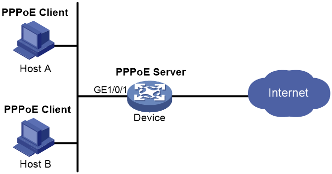
Router-initiated network structure
As shown in Figure 8, the PPPoE session is established between devices (Device A and Device B). All hosts share one PPPoE session for data transmission without being installed with PPPoE client software. This network structure is typically used by enterprises.
Figure 8 Router-initiated network structure
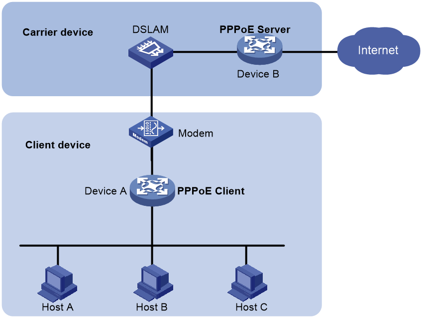
Host-initiated network structure
As shown in Figure 9, a PPPoE session is established between each host (PPPoE client) and the carrier device (PPPoE server). The service provider assigns an account to each host for billing and control. The host must be installed with PPPoE client software.
Figure 9 Host-initiated network structure
PPPoE packet structure
The format of PPPoE packets carries PPP packets in Ethernet frames. The encapsulation structure of the packets is as shown in Figure 10.
Figure 10 PPPoE packet structure
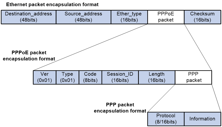
Table 6 Fields in the PPPoE packets
|
Field |
Description |
|
Destination address |
An Ethernet unicast destination address or Ethernet broadcast address (0xffffffffffff): · In the discovery phase, the field value is a unicast or broadcast address. The PPPoE client uses a broadcast address to find the PPPoE server, and then uses a unicast address after determining the PPPoE server. · In the session phase, this field must be the unicast address of the peer end determined during the discovery phase. |
|
Source_address |
Ethernet MAC address of the source device. |
|
Ether_type |
Set to 0x8863 (discovery phase) or 0x8864 (session phase). |
|
Ver |
4 bits long. This field represents the PPPoE version number. The value is 0x1. |
|
Type |
4 bits long. This field represents the PPPoE type. The value is 0x1. |
|
Code |
8 bits. This field represents the PPPoE packet type. Possible values include: · 0x00—Session data. · 0x09—PADI packet. · 0x07—PADO or PADT packet. · 0x19—PADR packet. · 0x65—PADS packet. |
|
Session_ID |
16 bits long. The value is fixed for a given PPP session and, in fact, defines a PPP session along with the Ethernet Source_address and Destination_address fields. The value of 0xffff is reserved for future use and must not be used. |
|
Length |
16 bits long. This field defines the length of the PPPoE payload. It does not include the length of the Ethernet or PPPoE headers. |
|
PPP packet |
For the PPP packet structure, see the frame format for PPP packet encapsulation in basic PPP concepts. |
Interaction process for PPPoE user onboarding
The PPPoE user onboarding process involves two phases: PPPoE negotiation and PPP negotiation. PPP negotiation includes LCP negotiation, PAP/CHAP authentication, NCP negotiation, and other phases.
PPPoE negotiation
In the PPPoE negotiation phase, the device assigns a session ID for the user's PPPoE access. A session ID uniquely identifies a virtual PPPoE link between the user and the device. The negotiation process of PPPoE is as shown in Figure 11.
1. The user broadcasts a PPPoE Active Discovery Initiation (PADI) packet, which contains the type of service the user wants.
2. Upon receiving this PADI packet, all access concentrators on the Ethernet (such as the device in the diagram) compare the requested service with their own capabilities. The device that can provide the service responds with a PPPoE Active Discovery Offer (PADO) packet.
3. The user might receive PADO packets from different devices. The user selects a device from the returned PADO packets based on certain conditions and sends to the device a non-broadcast session request packet, PPPoE Active Discovery Request (PADR). The PADR packet has the required service information encapsulated.
4. The selected device starts to enter the PPP session phase after receiving the PADR packet. The device will generate a session ID to uniquely identify the PPPoE session between the device and the host. The device includes this specific session ID in a session confirmation packet, PPPoE Active Discovery Session-confirmation (PADS), and sends the PADS packet to the user. If no errors occur, the device enters the PPP session phase. When the user receives the PADS packet, the user also enters the PPP session phase if no errors occur.
Figure 11 PPPoE negotiation process

PPP negotiation
PPP negotiation includes LCP negotiation, PAP/CHAP authentication, NCP negotiation, and other phases.
LCP negotiation
After the PPP negotiation phase starts, the LCP negotiation process starts first. The LCP negotiation process is as shown in Figure 12.
1. The user and the device send an LCP Configure-Request packet to each other.
2. After receiving the Configure-Request packet from the peer end, the local end responds appropriately based on the negotiation option support in the packet. For more information, see Table 7. If both ends have responded with a Configure-Ack packet, the LCP link has been successfully established. If not, both ends will continue to send requests.
¡ If the peer end responds with a Configure-Ack packet within the configured LCP negotiation interval and negotiation times, the LCP link has been successfully established.
¡ If the peer end has not responded with a Configure-Ack packet after the set LCP negotiation times, LCP negotiation will be terminated.
3. After the LCP link is successfully established, the device will periodically send LCP Echo-Requests to the user and then receive the Echo-Replies from the peer to detect whether the LCP link is normal and maintain the LCP connection.
Figure 12 Basic LCP negotiation process

Table 7 Response packet type list
|
Response packet type |
Description |
|
Configure-Ack |
If the end fully supports the LCP options of the peer end, the end responds with a Configure-Ack packet that fully carries the options in the request of the peer end. |
|
Configure-Nak |
If the end supports the negotiation options of the peer end but does not accept the negotiated content, the end responds with a Configure-Nak packet filled with the expected content. For example, if the MRU value of the peer is 1500 and the local end expects the MRU value of 1492, the local end will fill in 1492 in the Configure-Nak packet. |
|
Configure-Reject |
If the end does not support the negotiation options of the peer end, the end responds with a Configure-Reject packet carrying the unsupported options. |
Authentication phase
After the LCP negotiation is completed, the PPP link enters the authentication phase. Two authentication methods are supported: PAP authentication and CHAP authentication.
· PAP authentication
PAP is a two-way handshake protocol that authenticates a user by using a username and password. PAP transmits the username and password in plain text. Therefore, PAP is suitable for environments with relatively low network security requirements. The PAP authentication process is as shown in Figure 13.
a. The authenticatee sends the username and password to the authenticator.
b. The authenticator checks for this user in the user table at this end.
¡ If the user exists, the authenticator identifies whether the authentication password is correct.
- If the password is correct, the authenticator sends an Authenticate-ACK packet to the peer end to notify the peer end that it is allowed to enter the next phase of negotiation.
- If the password is not correct, the authenticator sends an Authenticate-NAK packet to the peer to notify the peer of authentication failure.
¡ If the user does not exist, the authentication will fail.
|
|
NOTE: After authentication failure, the link will not be directly closed. The link will be closed only when the number of authentication failures reaches a certain value. |
Figure 13 PAP authentication process

· CHAP authentication
CHAP is a three-way handshake protocol. CHAP transmits only the username rather than the user password over the network, so it is more secure than PAP. The authentication process of CHAP is as shown in Figure 14.
a. The authenticator initiates the authentication request, and sends a packet (Challenge) with a random number to the authenticatee and also sends the username to the authenticatee.
b. Upon receiving the authentication request from the authenticator, the authenticatee first identifies whether a CHAP password is configured on the local interface.
- If a CHAP password is configured, the authenticatee uses the hash algorithm to calculate a hash value based on the packet ID, configured password, and random number in the packet. Then, the authenticatee sends this hash value and the authenticatee's username (Response) back to the authenticator.
- If no CHAP password is configured, the authenticatee looks up the password corresponding to the username in the user table at this end based on the authenticator username in this packet. The authenticatee uses the hash algorithm to calculate a hash value based on the packet ID, the user's password, and the random number in the packet. The authenticatee sends the obtained hash value and the authenticatee's username back to the authenticator. (Response).
c. The authenticator uses the hash algorithm to calculate a hash value based on the packet ID, its saved password for the authenticatee, and the random number in the Challenge packet. The authenticator then compares the calculated hash value with the hash value in the Response packet. If the comparison result is consistent, authentication succeeds. If the comparison result is inconsistent, authentication fails.
Figure 14 CHAP authentication process

NCP negotiation
The main function of NCP negotiation is to negotiate network layer parameters of PPP packets, such as IPCP and IPv6CP, among which IPCP is the most common protocol. PPPoE users mainly obtain their IP addresses or IP address ranges for accessing the network through the IPCP protocol.
As shown in Figure 15, the NCP process is similar to the LCP process. When users and devices exchange Configure-Request packets and respond with Configure-Ack packets, NCP negotiation succeeds and users can normally access the network.
Figure 15 Basic NCP negotiation process

The following section will describe the commonly used IPCP and IPv6CP protocols in NCP negotiation.
· IPCP
The IPCP negotiation process is performed based on the PPP state machine. After both parties negotiate and they exchange configuration information through Configure-Request, Configure-Ack, and Configure-Nak packets, the IPCP state changes from initial (or closed) state to opened state finally. The condition for the IPCP state to become opened is that both the sender and receiver have sent and received Ack packets.
During the IPCP negotiation process, the negotiation packet can contain multiple options (parameters), such as IP address, gateway, and mask. The rejection or denial of each option does not affect the successful negotiation of IPCP, and IPCP also supports negotiation without options.
· IPv6CP
IPv6 Control Protocol (IPv6CP) is a network control protocol. IPv6CP is mainly responsible for configuring settings on both ends of a point-to-point link, enabling and disabling the IPv6 protocol module, and negotiating parameters such as interface ID and IPv6 compression protocol. IPv6CP uses the same packet exchange mechanism as the Link Control Protocol (LCP). However, the IPv6CP packets can be exchanged only when PPP reaches the network layer protocol phase. IPv6CP packets received before this phase will be dropped.
In the current software version, the IPv6CP negotiation options only support interface IDs and do not support the IPv6 compression protocols.
In an IPv6 network, PPP users and IPoE users both need to use the ND protocol or DHCPv6 protocol to allocate global unicast addresses and configuration information. The IA_PD option of the DHCPv6 protocol is used to allocate IPv6 prefixes to LAN interfaces in routed mode on CPEs.
PPPoE MTU and MRU negotiation method
During the interaction process of PPPoE user onboarding, the values of interface MTU and MRU will be negotiated, and then both sides will send and receive packets. The main negotiation methods include the following types.
The PPPoE connection is enabled to negotiate the MRU according to relevant standards
PPPoE discovery phase:
· If the user packet carries the PPP-Max-Payload field and the value is greater than 1492, the value will be compared with the MTU value on the BAS interface minus 8. The smaller value will be used as the negotiated value and named PPP_MRU_Max. This negotiated value is not the final MTU negotiation result, but one of the reference values.
· If the PPP-Max-Payload field carried in the user packet is less than or equal to 1492, PPP_MRU_Max takes the default value of 1492 as one of the reference values.
· If the user packet does not carry the PPP-Max-Payload field, then PPP_MRU_Max is set to 0 and not used as one of the reference values.
LCP negotiation phase:
· If the user carries the MRU field in the Config-Request packet during the LCP phase, the following rules apply:
¡ If the MRU carried in the user packet is equal to the PPP_MRU_Max negotiated in the PPPoE discovery phase, the MRU carried in the user packet will be used as the final MTU for the user.
¡ If the MRU carried in the user packet is not equal to the PPP_MRU_Max negotiated in the PPPoE discovery phase or the PPP_MRU_Max is 0, the MRU carried in the user packet will be compared with the MTU value on the VT interface minus 8. The smaller value will be used as the final MTU for the user.
· If the user's Config-Request packet during the LCP phase does not carry the MRU field, 1492 will be compared with the MTU value on the VT interface minus 8. The smaller value will be used as the final MTU for the user.
The PPPoE connection is disabled from negotiating the MRU according to relevant standards
PPPoE discovery phase:
· If the user packet carries the PPP-Max-Payload field, the smaller value between this value and the MTU on the BAS interface is used as the negotiated value and named PPP_MRU_Max. This value is not the final MTU negotiation result, but one of the reference values.
· If the user packet does not carry the PPP-Max-Payload field, the value for PPP_MRU_Max is the default value 0 and is not used as a reference value.
LCP negotiation phase:
· If the user includes the MRU field in the Config-Request packet during the LCP phase, the value will be compared with the MTU on the VT interface. The smaller value will be taken as the final MTU for the user.
· If the user does not include the MRU field in the Config-Request packet during the LCP phase, the following rules apply:
¡ If the user does not negotiate PPP_MRU_Max during the PPPoE discovery phase, the MTU on the VT interface will be used as the final MTU for the user.
¡ If PPP_MRU_Max is negotiated in the PPPoE discovery phase, the smaller value of the MTU on the VT interface and PPP-Max-Payload is used as the final MTU for the user.
Protocols and standards
RFC 2516: A Method for Transmitting PPP Over Ethernet (PPPoE)
Restrictions and guidelines for PPPoE
The PPPoE server feature supports the following interface views:
· Layer 3 Ethernet interface/subinterface view
· VLAN interface view
·
Configuring the PPPoE server
PPPoE server tasks at a glance
To configure PPPoE server, perform the following tasks:
1. Configuring a PPPoE session
2. (Optional.) Configuring a VA pool
3. (Optional.) Enabling the function of querying and configuring VA interfaces through MIB nodes
4. (Optional.) Setting the maximum number of PPPoE sessions
5. (Optional.) Limiting the PPPoE access rate
6. (Optional.) Configuring the NAS-Port-ID attribute
Configuring a PPPoE session
1. Enter system view.
system-view
2. Create a VT interface and enter VT interface view.
interface virtual-template number
3. Set PPP parameters.
For more information setting PPP parameters, see "Configuring PPP."
When configuring PPP authentication, use the PPPoE server as the authenticator.
4. Enable MRU verification for PPPoE applications.
ppp lcp echo mru verify [ minimum value ]
By default, MRU verification is disabled for PPPoE applications.
5. Return to system view.
quit
6. Enter interface view.
interface interface-type interface-number
7. Enable the PPPoE server on the interface and bind this interface to the specified VT interface.
pppoe-server bind virtual-template number
By default, the PPPoE server is disabled on the interface.
8. (Optional.) Configure an access concentrator (AC) name for the PPPoE server.
pppoe-server tag ac-name name
By default, the AC name for the PPPoE server is the device name.
PPPoE clients can choose a PPPoE server according to the AC name. The PPPoE client on H3C devices do not support this feature.
9. (Optional.) Enable the PPPoE server to support the ppp-max-payload tag and specify a range for the PPP maximum payload.
pppoe-server tag ppp-max-payload [ minimum minvalue maximum maxvalue ]
By default, The PPPoE server does not support the ppp-max-payload tag.
10. (Optional.) Set a service name for the PPPoE server
pppoe-server tag service-name name
By default, the PPPoE server does not have a service name.
11. (Optional) Set the response delay time for user access.
pppoe-server access-delay delay-time
By default, no response delay time is set.
12. Return to system view.
quit
13. Configure the PPPoE server to perform authentication, authorization, and accounting for PPP users.
For more information, see User Access and Authentication Configuration Guide.
Configuring a VA pool
About this task
The PPPoE server creates a VA interface for a PPPoE session to transmit packets between PPPoE and PPP, and removes the VA interface when the user goes offline. Creating and removing VA interfaces take time.
You can configure VA pools to improve the performance of PPPoE session establishment and termination. A VA pool contains a group of automatically numbered VA interfaces. The PPPoE server selects a VA interface from the pool for a requesting user and release the VA interface when the user goes offline. When a VA pool is exhausted, the system creates VA interfaces for new PPPoE sessions, and removes those VA interfaces when the users go offline.
On a VT interface, you can create one global VA pool and one regional VA pool per member device for interfaces bound with the VT interface.
· The global VA pool contains VA interfaces for logical interfaces that might span multiple devices, such as Ethernet aggregate interfaces.
· The regional VA pool contains VA interfaces for interfaces that do not span multiple devices, such as Ethernet interfaces.
Restrictions and guidelines
To change the capacity of a VA pool, you must delete the previous configuration and reconfigure the VA pool.
Creating or removing a VA pool takes time. During the process of creating or removing a VA pool, users can go online or offline, but the VA pool does not take effect.
If the system fails to create a VA pool because of insufficient resources, you can view the available resources by using the display pppoe-server va-pool command.
VA pools are memory intensive. Set their capacity depending on your network requirements.
Deleting a VA pool does not log off the users who are using VA interfaces in the VA pool.
Procedure
1. Enter system view.
system-view
2. Create a VA pool.
pppoe-server virtual-template template-number va-pool va-volume
Enabling the function of querying and configuring VA interfaces through MIB nodes
About this task
When a large VA pool is configured or a large number of users come online, a large number of VA interfaces are created on the device. In most cases, the administrator is not concerned with VA interfaces when obtaining device information through MIB nodes. Therefore, you cannot query and configure VA interfaces through MIB nodes by default. In this case, the device ignores the VA interface configuration and query requests from the NMS. This improves the efficiency of obtaining information about the other interfaces, improves the user experience, reduces the device workload, and saves CPU resources.
To query and configure VA interfaces through MIB nodes, enable this function.
Procedure
1. Enter system view.
system-view
2. Enable the function of querying and configuring VA interfaces through MIB nodes.
snmp virtual-access visible
By default, the function of querying and configuring VA interfaces through MIB nodes is disabled.
For more information about this command, see SNMP in Network Management and Monitoring Command Reference.
Setting the maximum number of PPPoE sessions
About this task
PPPoE can establish a session when none of the following limits are reached:
· Limit for a user on an interface.
· Limit for a VLAN on an interface.
· Limit on an interface.
· Limit on a device.
Restrictions and guidelines for maximum number of PPPoE sessions
New maximum number settings apply only to subsequently established PPPoE sessions.
The maximum number of PPPoE sessions set for a device cannot be greater than the maximum number of PPPoE sessions supported by the device. The maximum number of PPPoE sessions supported by a device varies by license or device model.
Setting the maximum number of PPPoE sessions in interface view
1. Enter system view.
system-view
2. Enter interface view.
interface interface-type interface-number
The PPPoE server is enabled on the interface.
3. Set the maximum number of PPPoE sessions.
¡ Set the maximum number of PPPoE sessions on an interface.
pppoe-server session-limit number
By default, the number of PPPoE sessions on an interface is not limited.
¡ Set the maximum number of PPPoE sessions for a VLAN.
pppoe-server session-limit per-vlan number
By default, the number of PPPoE sessions for a VLAN on an interface is not limited.
¡ Set the maximum number of PPPoE sessions for a user.
pppoe-server session-limit per-mac number
By default, a user is allowed to create a maximum of 100 PPPoE sessions.
Setting the maximum number of PPPoE sessions in system view
1. Enter system view.
system-view
2. Set the maximum number of PPPoE sessions.
pppoe-server session-limit total number
By default, the number of PPPoE sessions is not limited.
Limiting the PPPoE access rate
About this task
The device can limit the rate at which a user (identified by an MAC address) can create PPPoE sessions on an interface. If the number of PPPoE requests within the monitoring time exceeds the configured threshold, the device discards the excessive requests, and outputs log messages. If the blocking time is set to 0, the device does not block any requests, and it only outputs log messages.
The device uses a monitoring table and a blocking table to control PPP access rates:
· Monitoring table—Stores a maximum of 8000 monitoring entries. Each entry records the number of PPPoE sessions created by a user within the monitoring time. When the monitoring entries reach the maximum, the system stops monitoring and blocking session requests from new users. The aging time of monitoring entries is determined by the session-request-period argument. When the timer expires, the system starts a new round of monitoring for the user.
· Blocking table—Stores a maximum of 8000 blocking entries. The system creates a blocking entry if the access rate of a user reaches the threshold, and blocks requests from that user. When the blocking entries reach the maximum number, the system stops blocking session requests from new users and it only outputs log messages. The aging time of the blocking entries is determined by the blocking-period argument. When the timer expires, the system starts a new round of monitoring for the user.
Restrictions and guidelines
If the access rate setting is changed, the system removes all monitoring and blocking entries, and uses the new settings to limit PPPoE access rates.
Procedure
1. Enter system view.
system-view
2. Enter interface view.
interface interface-type interface-number
The PPPoE server is enabled on the interface.
3. Set the PPPoE access limit.
pppoe-server throttle per-mac session-requests session-request-period blocking-period
By default, the PPPoE access rate is not limited.
Configuring the NAS-Port-ID attribute
About this task
The PPPoE server on a BAS device uses the RADIUS NAS-Port-ID attribute to send the access line ID received from a DSLAM device to the RADIUS server. The access line ID includes the circuit-id and remote-id. The RADIUS server compares the received NAS-Port-ID attribute with the local line ID information to verify the location of the user.
You can configure the content of the NAS-Port-ID attribute that the PPPoE server sends to the RADIUS server.
Procedure
1. Enter system view.
system-view
2. Enter interface view.
interface interface-type interface-number
The PPPoE server is enabled on the interface.
3. Configure the content of the NAS-Port-ID attribute.
pppoe-server access-line-id content { all [ separator ] | circuit-id | remote-id }
By default, the NAS-Port-ID attribute contains only the circuit-id.
4. Configure the NAS-Port-ID attribute to include the BAS information automatically.
pppoe-server access-line-id bas-info [ cn-163 ]
By default, the NAS-Port-ID attribute does not include the BAS information automatically.
5. Configure the PPPoE server to trust the access line ID in received packets.
pppoe-server access-line-id trust
By default, the PPPoE server does not trust the access line ID in received packets.
6. Configure the format that is used to parse the circuit-id.
pppoe-server access-line-id circuit-id parse-mode { cn-telecom | tr-101 }
The default mode is TR-101.
7. Configure the transmission format for the circuit-id.
pppoe-server access-line-id circuit-id trans-format { ascii | hex }
The default format is a string of characters.
8. Configure the transmission format for the remote-id.
pppoe-server access-line-id remote-id trans-format { ascii | hex }
The default format is a string of characters.
Configuring a PPPoE client
Operation mode
A PPPoE session can operate in one of the following modes:
· Permanent mode—A PPPoE session is established immediately when the line is physically up. This type of session remains until the physical link comes down or until the session is disconnected.
· On-demand mode—A PPPoE session is established when there is a demand for data transmission instead of when the line is physically up. It is terminated when idled for a specific period of time.
· Diagnostic mode—A PPPoE session is established immediately after the device configurations finish. The device automatically terminates the PPPoE session and then tries to re-establish a PPPoE session at a pre-configured interval. By establishing and terminating PPPoE sessions periodically, you can monitor the operating status of the PPPoE link.
The PPPoE session operating mode is determined by your configuration on the dialer interface:
· Permanent mode—Used when you set the link idle time to 0 by using the dialer timer idle command and do not configure the dialer diagnose command.
· On-demand mode—Used when you set the link idle time to a non-zero value by using the dialer timer idle command and do not configure the dialer diagnose command.
· Diagnostic mode—Used when you configure the dialer diagnose command.
PPPoE client tasks at a glance
To configure a PPPoE client, perform the following tasks:
1. Configuring a dialer interface
2. Configuring a PPPoE session
3. (Optional.) Resetting a PPPoE session
Configuring a dialer interface
About this task
Before establishing a PPPoE session, you must first create a dialer interface and configure bundle DDR on the interface. Each PPPoE session uniquely corresponds to a dialer bundle, and each dialer bundle uniquely corresponds to a dialer interface. A PPPoE session uniquely corresponds to a dialer interface.
Procedure
1. Enter system view.
system-view
2. Create a dialer group and configure a dial rule.
dialer-group group-number rule { ip | ipv6 } { deny | permit | acl { acl-number | name acl-name } }
Configure this command only when the PPPoE session operates in on-demand mode.
3. Create a dialer interface and enter its view.
interface dialer number
4. Assign an IP address to the interface.
ip address { address mask | ppp-negotiate }
By default, no IP address is configured.
5. Enable bundle DDR on the interface.
dialer bundle enable
By default, bundle DDR is disabled.
6. Associate the interface with the dial rule by associating the interface with the corresponding dialer group.
dialer-group group-number
By default, a dialer interface is not assigned to any dialer group.
Configure this command only when the PPPoE session operates in on-demand mode.
7. Configure the link-idle timeout timer.
dialer timer idle idle [ in | in-out ]
The default setting is 120 seconds.
When this timer is set to 0 seconds, the PPPoE session operates in permanent mode. Otherwise, the PPPoE session operates in on-demand mode.
8. Configure the DDR application to operate in diagnostic mode.
dialer diagnose [ interval interval ]
By default, the DDR application operates in non-diagnostic mode.
Execute this command only when the PPPoE session operates in diagnostic mode.
9. (Optional.) Set the auto-dial interval.
dialer timer autodial autodial-interval
The default setting is 300 seconds.
DDR starts the auto-dial timer after the link is disconnected and originates a new call when the auto-dial timer expires.
As a best practice, set a shorter auto-dial interval for DDR to soon originate a new call.
10. (Optional.) Set the MTU for the dialer interface
mtu size
By default, the MTU on a dialer interface is 1500 bytes.
The dialer interface fragments a packet that exceeds the configured MTU, and adds a 2-byte PPP header and a 6-byte PPPoE header to each fragment. You should modify the MTU of a dialer interface to make sure the total length of any fragment packet is less than the MTU of the physical interface.
11. (Optional.) Set the TCP MSS for the dialer interface.
tcp mss value
By default, the TCP MSS is not set for an interface.
Typically, the TCP MSS is the IP MTU of the outgoing interface minus 40. For the dialer interface of a PPPoE client application, you must modify its TCP MSS to 1452. Then, the total length of a packet will not exceed the MTU of the interface of the corresponding PPPoE session after a 2-byte PPP header, 6-byte PPPoE header, and 40-byte IP header are added to the packet.
For more information this command, see IP performance optimization commands in Network Connectivity Command Reference.
Configuring a PPPoE session
About this task
After a PPPoE session is successfully established, the system automatically creates a VA interface for exchanging packets with the peer. To display information about VA interfaces, execute the display interface virtual-access command. VA interfaces cannot be manually configured.
After the PPPoE session is terminated, the corresponding VA interface is automatically deleted.
Restrictions and guidelines
On a fit AP, do not use both a VLAN interface and a dialer interface as uplink interfaces. If you do that, the AP might fail to come online.
Procedure
1. Enter system view.
system-view
2. Enter interface view.
interface interface-type interface-number
3. Create a PPPoE session and specify a dialer bundle for the session.
pppoe-client dial-bundle-number number [ no-hostuniq ]
The number argument in this command must take the same value as the configured dialer interface number.
Resetting a PPPoE session
About this task
After you reset a PPPoE session in permanent mode, the device establishes a new PPPoE session when the autodial timer expires.
After you reset a PPPoE session in on-demand mode, the device establishes a new PPPoE session when there is a demand for data transmission.
Procedure
To reset a PPPoE session, execute the following command in user view:
reset pppoe-client { all | dial-bundle-number number }
Display and maintenance commands for PPPoE
Display and maintenance commands for PPPoE server
Execute display commands in any view and reset commands in user view.
|
Task |
Command |
|
Display PPPoE server negotiation packet statistics. |
display pppoe-server packet statistics |
|
Display packet statistics for PPPoE sessions. |
display pppoe-server session packet [ interface interface-type interface-number ] |
|
Display summary information for PPPoE sessions. |
display pppoe-server session summary [ interface interface-type interface-number ] |
|
Display information about blocked users. |
display pppoe-server throttled-mac [ interface interface-type interface-number ] |
|
Display VA pool information. |
display pppoe-server va-pool |
|
Clear PPPoE sessions. |
reset pppoe-server { all | interface interface-type interface-number | virtual-template number } |
|
Clear PPPoE server negotiation packet statistics. |
reset pppoe-server packet statistics |
Display and maintenance commands for PPPoE client
Execute display commands in any view and reset commands in user view.
|
Task |
Command |
|
Display summary information for a PPPoE session. |
display pppoe-client session summary [ dial-bundle-number number ] |
|
Display the protocol packet statistics for a PPPoE session. |
display pppoe-client session packet [ dial-bundle-number number ] |
|
Clear the protocol packet statistics for a PPPoE session. |
reset pppoe-client session packet [ dial-bundle-number number ] |
PPPoE configuration examples
Example: Configuring a PPPoE client in permanent mode
Network configuration
As shown in Figure 16, Device serves as a PPPoE server. Configure AC as a PPPoE client operating in permanent mode.

Procedure
1. Configure Device as the PPPoE server:
# Configure an IP address for Virtual-Template 1 and specify an IP address for the peer.
<Device> system-view
[Device] interface virtual-template 1
[Device-Virtual-Template1] ip address 1.1.1.1 255.0.0.0
[Device-Virtual-Template1] remote address 1.1.1.2
# Configure Virtual-Template 1 to authenticate the peer by using PAP.
[Device-Virtual-Template1] ppp authentication-mode pap domain dm1
[Device-Virtual-Template1] quit
# Enable the PPPoE server on GigabitEthernet 1/0/1, and bind the interface to Virtual-Template 1.
[Device] interface gigabitethernet 1/0/1
[Device-GigabitEthernet1/0/1] pppoe-server bind virtual-template 1
[Device-GigabitEthernet1/0/1] quit
# Configure a PPPoE user.
[Device] local-user user1 class network
[Device-luser-network-user1] password simple 123456TESTplat&!
[Device-luser-network-user1] service-type ppp
[Device-luser-network-user1] quit
# Configure local AAA for the PPP users in ISP domain dm1.
[Device] domain dm1
[Device-isp-dm1] authentication ppp local
[Device-isp-dm1] accounting ppp local
[Device-isp-dm1] authorization ppp local
[Device-isp-dm1] quit
2. Configure AC as the PPPoE client:
# Create dialer group 1 and configure a dial rule for it.
<AC> system-view
[AC] dialer-group 1 rule ip permit
# Enable bundle DDR on Dialer 1.
[AC] interface dialer 1
[AC-Dialer1] dialer bundle enable
# Associate Dialer 1 with dialer group 1.
[AC-Dialer1] dialer-group 1
# Configure Dialer 1 to obtain an IP address through PPP negotiation.
[AC-Dialer1] ip address ppp-negotiate
# On Dialer 1, configure the PAP username and password sent from AC to Device as user1 and 123456TESTplat&! when AC is authenticated by Device by using PAP.
[AC-Dialer1] ppp pap local-user user1 password simple 123456TESTplat&!
[AC-Dialer1] quit
# Configure a PPPoE session that corresponds to dialer bundle 1 (dialer bundle 1 corresponds to Dialer 1).
[AC] interface vlan-interface 1
[AC-Vlan-interface1] pppoe-client dial-bundle-number 1
[AC-Vlan-interface1] quit
# Configure the PPPoE session to operate in permanent mode.
[AC] interface dialer 1
[AC-Dialer1] dialer timer idle 0
# Set the DDR auto-dial interval to 60 seconds.
[AC-Dialer1] dialer timer autodial 60
[AC-Dialer1] quit
# Configure a static route.
[AC] ip route-static 1.1.1.1 255.0.0.0 dialer 1
Verifying the configuration
# Display summary information about the PPPoE session established between AC and Device (PPPoE server).
[AC] display pppoe-client session summary
Bundle ID Interface VA RemoteMAC LocalMAC State
1 1 GE1/0/1 VA0 00e0-1400-4300 00e0-1500-4100 SESSION
Example: Configuring a PPPoE client in on-demand mode
Network configuration
As shown in Figure 17, Device serves as a PPPoE server. Configure AC as a PPPoE client operating in on-demand mode, and set the link idle-timeout timer to 150 seconds.

Procedure
1. Configure Device as the PPPoE server:
# Configure an IP address for Virtual-Template 1 and specify an IP address for the peer.
<Device> system-view
[Device] interface virtual-template 1
[Device-Virtual-Template1] ip address 1.1.1.1 255.0.0.0
[Device-Virtual-Template1] remote address 1.1.1.2
# Configure Virtual-Template 1 to authenticate the peer by using PAP.
[Device-Virtual-Template1] ppp authentication-mode pap domain dm1
[Device-Virtual-Template1] quit
# Enable the PPPoE server on GigabitEthernet 1/0/1, and bind the interface to Virtual-Template 1.
[Device] interface gigabitethernet 1/0/1
[Device-GigabitEthernet1/0/1] pppoe-server bind virtual-template 1
[Device-GigabitEthernet1/0/1] quit
# Configure a PPPoE user.
[Device] local-user user1 class network
[Device-luser-network-user1] password simple 123456TESTplat&!
[Device-luser-network-user1] service-type ppp
[Device-luser-network-user1] quit
# Configure local AAA for the PPP users in ISP domain dm1.
[Device] domain dm1
[Device-isp-dm1] authentication ppp local
[Device-isp-dm1] accounting ppp local
[Device-isp-dm1] authorization ppp local
[Device-isp-dm1] quit
2. Configure AC as the PPPoE client.
# Create dialer group 1 and configure a dial rule for it.
<AC> system-view
[AC] dialer-group 1 rule ip permit
# Enable bundle DDR on Dialer 1.
[AC] interface dialer 1
[AC-Dialer1] dialer bundle enable
# Associate Dialer 1 with dialer group 1.
[AC-Dialer1] dialer-group 1
# Configure Dialer 1 to obtain an IP address through PPP negotiation.
[AC-Dialer1] ip address ppp-negotiate
# On Dialer 1, configure the PAP username and password sent from AC to Device as user1 and 123456TESTplat&! when AC is authenticated by Device by using PAP.
[AC-Dialer1] ppp pap local-user user1 password simple 123456TESTplat&!
[AC-Dialer1] quit
# Configure a PPPoE session that corresponds to dialer bundle 1 (dialer bundle 1 corresponds to Dialer 1).
[AC] interface vlan-interface 1
[AC-Vlan-interface1] pppoe-client dial-bundle-number 1
[AC-Vlan-interface1] quit
# Configure a static route.
[AC] ip route-static 1.1.1.1 255.0.0.0 dialer 1
# Set the link-idle timeout timer to 150 seconds.
[AC] interface dialer 1
[AC-Dialer1] dialer timer idle 150
[AC-Dialer1] quit
Verifying the configuration
# Display summary information about the PPPoE session established between AC and Device (PPPoE server).
[AC] display pppoe-client session summary
Bundle ID Interface VA RemoteMAC LocalMAC State
1 1 GE1/0/1 VA0 00e0-1400-4300 00e0-1500-4100 SESSION
Example: Configuring a PPPoE client in diagnostic mode
Network configuration
As shown in Figure 18, Device serves as a PPPoE server. Configure AC as a PPPoE client operating in diagnostic mode, and set the diagnostic interval to 200 seconds.

Procedure
1. Configure Device as the PPPoE server:
# Configure an IP address for Virtual-Template 1 and specify an IP address for the peer.
<Device> system-view
[Device] interface virtual-template 1
[Device-Virtual-Template1] ip address 1.1.1.1 255.0.0.0
[Device-Virtual-Template1] remote address 1.1.1.2
# Configure Virtual-Template 1 to authenticate the peer by using PAP.
[Device-Virtual-Template1] ppp authentication-mode pap domain dm1
[Device-Virtual-Template1] quit
# Enable the PPPoE server on GigabitEthernet 1/0/1, and bind the interface to Virtual-Template 1.
[Device] interface gigabitethernet 1/0/
[Device-GigabitEthernet1/0/1] pppoe-server bind virtual-template 1
[Device-GigabitEthernet1/0/1] quit
# Configure a PPPoE user.
[Device] local-user user1 class network
[Device-luser-network-user1] password simple 123456TESTplat&!
[Device-luser-network-user1] service-type ppp
[Device-luser-network-user1] quit
# Configure local AAA for the PPP users in ISP domain dm1.
[Device] domain dm1
[Device-isp-dm1] authentication ppp local
[Device-isp-dm1] accounting ppp local
[Device-isp-dm1] authorization ppp local
[Device-isp-dm1] quit
2. Configure AC as the PPPoE client.
# Create dialer group 1 and configure a dial rule for it.
<AC> system-view
[AC] dialer-group 1 rule ip permit
# Enable bundle DDR on Dialer 1.
[AC] interface dialer 1
[AC-Dialer1] dialer bundle enable
# Associate Dialer 1 with dialer group 1.
[AC-Dialer1] dialer-group 1
# Configure Dialer 1 to obtain an IP address through PPP negotiation.
[AC-Dialer1] ip address ppp-negotiate
# On Dialer 1, configure the PAP username and password sent from AC to Device as user1 and 123456TESTplat&! when AC is authenticated by Device by using PAP.
[AC-Dialer1] ppp pap local-user user1 password simple 123456TESTplat&!
[AC-Dialer1] quit
# Configure a PPPoE session that corresponds to dialer bundle 1 (dialer bundle 1 corresponds to Dialer 1).
[AC] interface vlan-interface 1
[AC-Vlan-interface1] pppoe-client dial-bundle-number 1
[AC-Vlan-interface1] quit
# Configure the PPPoE session to operate in diagnostic mode, and set the diagnostic interval to 200 seconds.
[AC] interface dialer 1
[AC-Dialer1] dialer diagnose interval 200
# Set the DDR auto-dial interval to 10 seconds.
[AC-Dialer1] dialer timer autodial 10
Verifying the configuration
# Display summary information about the PPPoE session established between AC and Device (PPPoE server).
[AC] display pppoe-client session summary
Bundle ID Interface VA RemoteMAC LocalMAC State
1 1 GE1/0/1 VA0 00e0-1400-4300 00e0-1500-4100 SESSION
