- Table of Contents
-
- H3C G6 Servers Storage Controller User Guide-6W103
- 00-Preface
- 01-Storage controller overview
- 02-Storage controller features
- 03-Configuring a VROC SATA RAID controller
- 04-Configuring an NVMe VROC module
- 05-Configuring an LSI-9540 or 9560 storage controller
- 06-Configuring an LSI-9660 series storage controller
- 07-Configuring a P460, P2404 or P4408 storage controller
- 08-Configuring an LSI 9500 series storage controller
- 09-Configuring a RAID-MARVELL-SANTACRUZ-LP-2i storage controller
- 10-Configuring a RAID-MARVELL-M.2 storage controller
- 21-Appendix A Troubleshooting storage controllers
- 22-Appendix B RAID arrays and fault tolerance
- Related Documents
-
| Title | Size | Download |
|---|---|---|
| 09-Configuring a RAID-MARVELL-SANTACRUZ-LP-2i storage controller | 1.63 MB |
Configuring a RAID-MARVELL-SANTACRUZ-LP-2i storage controller
|
|
NOTE: The BIOS screens might vary by the BIOS version. The screenshots in this chapter are for illustration only. |
About the RAID-MARVELL-SANTACRUZ-LP-2i storage controller
The RAID-MARVELL-SANTACRUZ-LP-2i standard storage controller can be installed onto a riser card to provide limited RAID support for the system, which improves read/write performance and data security.
This section introduces the RAID-MARVELL-SANTACRUZ-LP-2i storage controller in a rack server.
Features
RAID levels
Table 1 shows the number of drives required by each RAID level and the maximum number of failed drives supported by each RAID level. In the table, Just a Bunch of Disk (JBOD) mode provides similar features as RAID 0 and requires only 1 drive. JBOD does not support redundancy. For more information about RAID levels, see "Appendix B RAID arrays and fault tolerance."
Table 1 RAID levels and the numbers of drives for each RAID level
|
RAID level |
Min. drives required |
Max. failed drives |
|
JBOD |
1 |
0 |
|
RAID 0 |
2 |
0 |
|
RAID 1 |
2 |
1 |
Restrictions and guidelines for RAID configuration
· As a best practice, install drives that do not contain RAID information.
· You must use the storage controller together with a RAID level because physical drives cannot be identified in the OS.
· The RAID-MARVELL-SANTACRUZ-LP-2i storage controller supports only NVMe M.2 SSDs.
· For efficient use of storage, use drives that have the same capacity to build a RAID. If the drives have different capacities, the lowest capacity is used across all drives in the RAID.
Configuring RAID arrays in UEFI mode
RAID-MARVELL-SANTACRUZ-LP-2i storage controller cannot be configured in legacy mode. This section describes how to configure RAID arrays through a RAID-MARVELL-SANTACRUZ-LP-2i storage controller in UEFI mode. For more information about how to access the BIOS setup utility and set the boot mode to UEFI, see the BIOS user guide for the server.
Controller configuration tasks at a glance
To configure controller settings in UEFI mode, perform the following tasks:
· Accessing the storage controller configuration screen
· Viewing physical drive information
· Viewing logical drive information
· Configuring logical drive media patrol
· Viewing namespace information
· Viewing storage controller information
Accessing the storage controller configuration screen
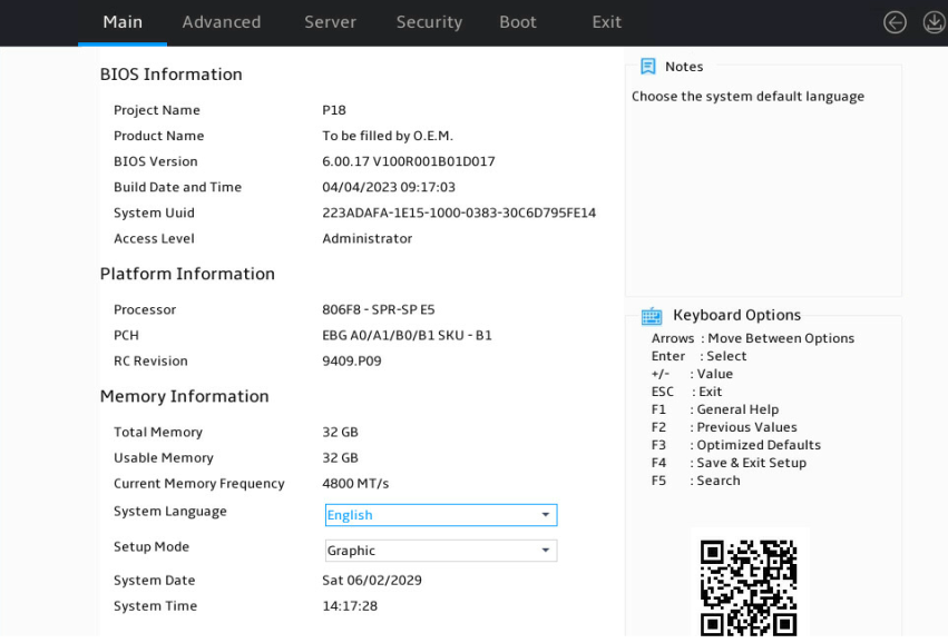
1. After the server is powered on or restarts, access the BIOS. Press Delete, Esc, or F2 as prompted during server POST to open the BIOS setup screen as shown in Figure 1.
For how to navigate screens and modify settings, see the operation instructions at the lower right corner.
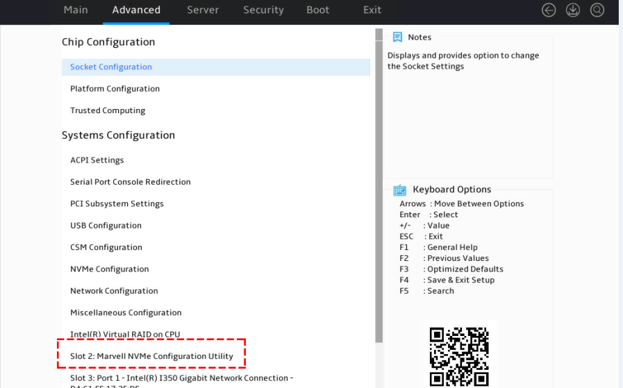
2. Enter the controller management screen.
a. On the top navigation bar, click Advanced.
b. Click Dynamic Device Configuration or UEFI HII Configuration, or proceed to the next step, depending on the BIOS version.
3. Select the target storage controller and then press Enter. In this example, the storage controller model is Marvell NVMe Configuration Utility.
The storage controller configuration screen opens. Tasks can be performed from this screen are shown in Table 2.
Figure 3 Storage controller configuration screen
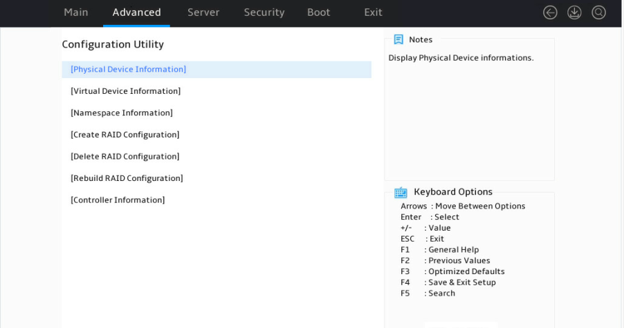
Table 2 Storage controller configuration tasks
|
Task type |
Option |
Description |
|
Information query |
Physical Device Information |
Display installed physical drives and details. |
|
Virtual Device Information |
Display created logical drives and details. For logical drives in RAID 1, media patrol is supported. |
|
|
Namespace Information |
Display information about namespace*. |
|
|
Controller Information |
Display storage controller basic information. |
|
|
RAID configuration |
Create RAID Configuration |
Create RAIDs. |
|
Delete RAID Configuration |
Delete RAIDs. |
|
|
Rebuild RAID Configuration |
Rebuild RAIDs. |
|
|
Namespace*: Memory space of an NVMe M.2 SSD that is logically divided. Namespaces are independent of each other and can be formatted or encrypted independently. The RAID-MARVELL-SANTACRUZ-LP-2i storage controller does not support namespaces. |
||
Configuring a RAID array
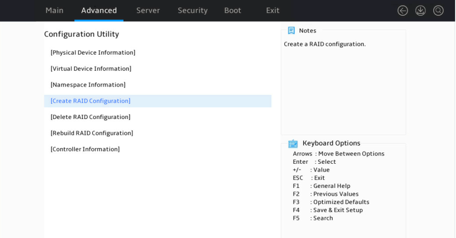
1. Access the storage controller configuration screen, select Create RAID Configuration, and press Enter.
Figure 4 Storage controller configuration screen
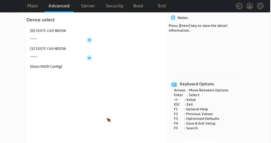
2. Set the state of the two member drives to Enabled, select Goto RAID Config, and press Enter.
Figure 5 Selecting member drives
3. Configure parameters as needed, set the Would you like to create this virtual disk? field to YES, select Accept, and press Enter.
The parameter description is in Table 3.
Figure 6 Configuring RAID information
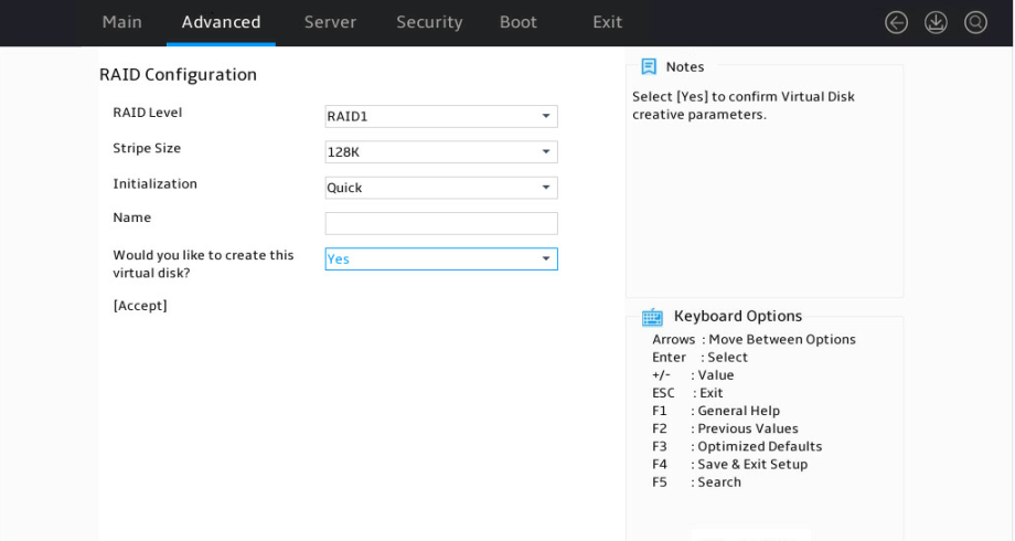
|
Parameter |
Description |
|
RAID Level |
RAID level. Options include: · JBOD. · RAID 0. · RAID 1. |
|
Stripe Size |
Stripe size. Options include: · 128K. · 256K. · 512K. |
|
Initialization |
Initialization methods. Options include: · Quick—Default. · Back Ground—This option is supported only in RAID 1. · None. |
|
Name |
Name of a logical drive. |
Deleting a RAID array
This feature deletes damaged RAID arrays or RAID arrays that cannot meet requirements.
To delete a RAID array:
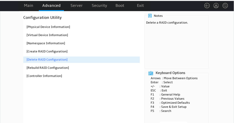
1. Access the storage controller configuration screen, select Delete RAID Configuration, and press Enter.
Figure 7 Storage controller configuration screen
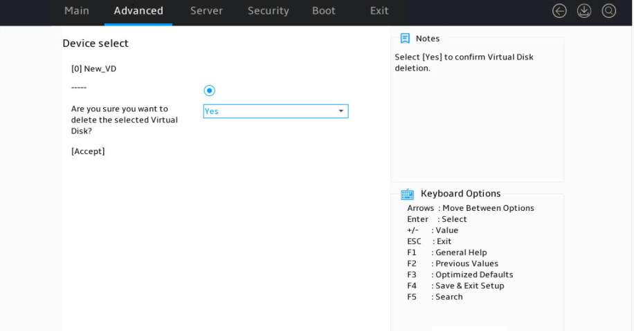
2. Perform the following tasks:
a. Select a target logical drive and set its state to Enabled.
b. Set the Are you sure you want to delete the selected virtual Disk? field to Yes.
c. Select Accept and press Enter.
Figure 8 Deleting a RAID array
Rebuilding a RAID array
This feature rebuilds the RAID array for drive replacement when a member drive in RAID 1 failed.
To rebuild a RAID array:
1. Access the storage controller configuration screen, select Rebuild RAID Configuration, and press Enter.
Figure 9 Storage controller configuration screen
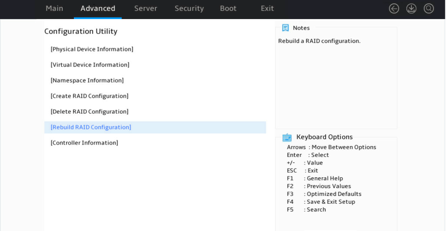
2. Perform tasks based on the following guidelines:
¡ If the screen does not display any logical drives for selection, no logical drive is available or no logical drive can be rebuilt.
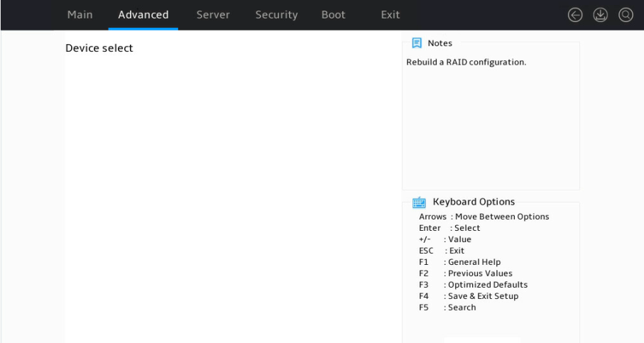
¡ If the screen displays logical drives for selection, set the target logical drive state to Enabled, select Goto PD Select, and press Enter.
3. Perform tasks based on the following guidelines:
¡ If the screen does not display any physical drives, no physical drive is available.
¡ If the screen displays physical drives for selection, select a target physical drive and press Enter.
Figure 10 Selecting a physical drive
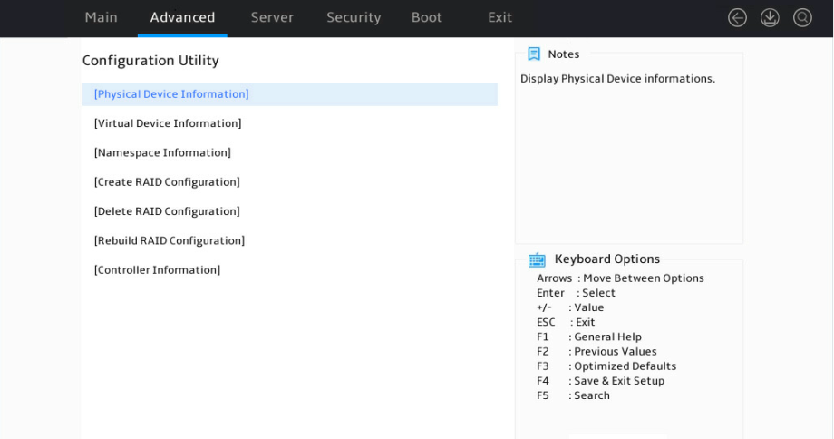
Viewing physical drive information
1. Access the storage controller configuration screen, select Physical Device Information, and press Enter.
Figure 11 Storage controller configuration screen
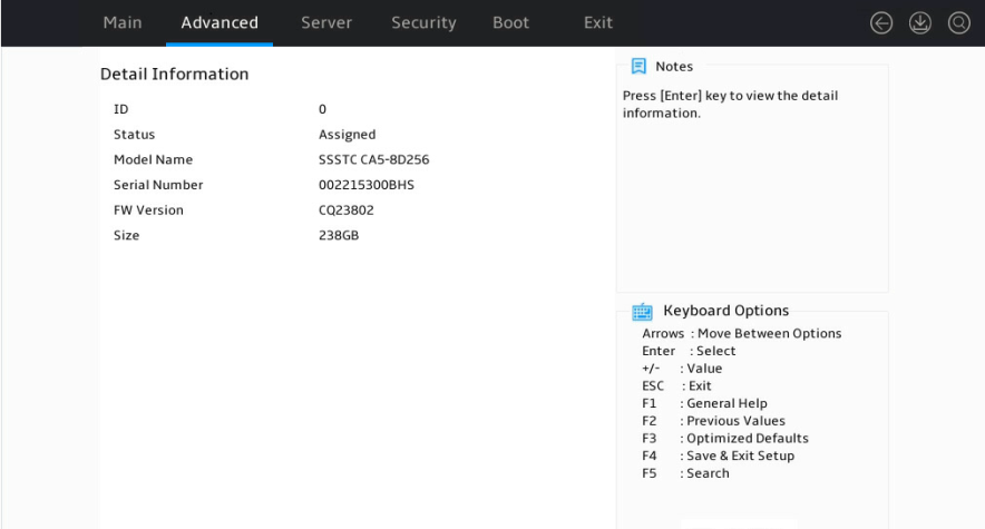
2. Select a target physical drive and press Enter.
Figure 12 Selecting a physical drive

The physical drive detail screen opens. Parameters are as described in Table 4.
Figure 13 Physical drive detail screen
|
Parameter |
Description |
|
ID |
Physical drive slot information. Options include: · 0—Slot for physical drive marked Bay 1. · 1—Slot for physical drive marked Bay 2. |
|
Status |
Physical drive status. Options include: · Unconfigured—Not used by any RAID array and unidentifiable in the OS. · Assigned—Used by a RAID array and identifiable in the OS. |
|
Model Name |
Physical drive model. |
|
Serial Number |
Physical drive serial number. |
|
FW Version |
Physical drive firmware version. |
|
Size |
Physical drive capacity. |
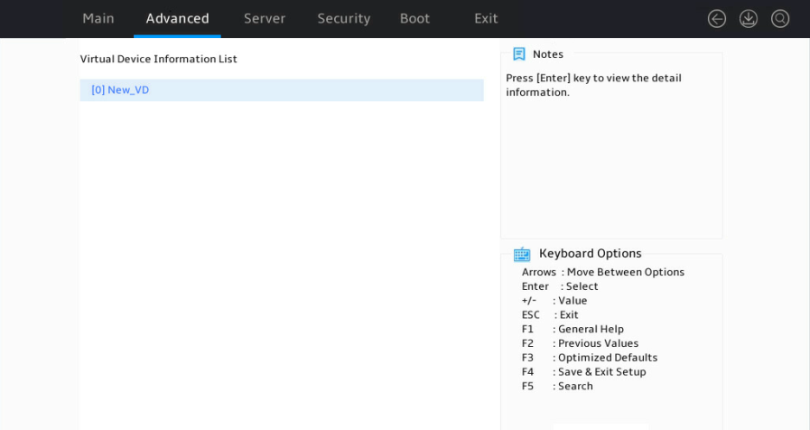
Viewing logical drive information
1. Access the storage controller configuration screen, select Virtual Device Information, and press Enter.
Figure 14 Storage controller configuration screen
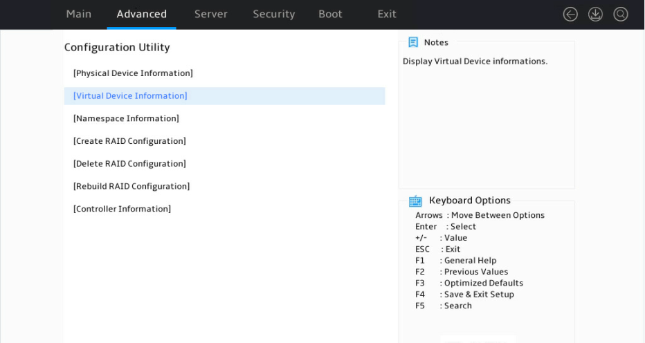
2. Select a target logical drive and press Enter.
Figure 15 Selecting a logical drive

The logical drive detail screen opens. Parameters are as described in Table 5.
Figure 16 Logical drive detail screen
|
Parameter |
Description |
|
ID |
Logical drive number. Options include 0 and 1. |
|
Name |
Logical drive name. |
|
Status |
Logical drive status. Options include: · Functional. · Degrade. · Offline. |
|
BGA Type |
Background task type. Options include: · Initialization—RAID initialization in progress. · Rebuild—RAID rebuilding in progress. · MediaPatrol—Media patrol for logical drives in progress. · None. |
|
BGA Status |
Background task status. Options include: · None. · RUNNING—Task progress in percentage. |
|
Member Count |
Number of member drives. |
|
Member ID |
Member drive ID. |
|
Stripe Block |
Stripe size. |
|
Size |
Logical drive capacity. |
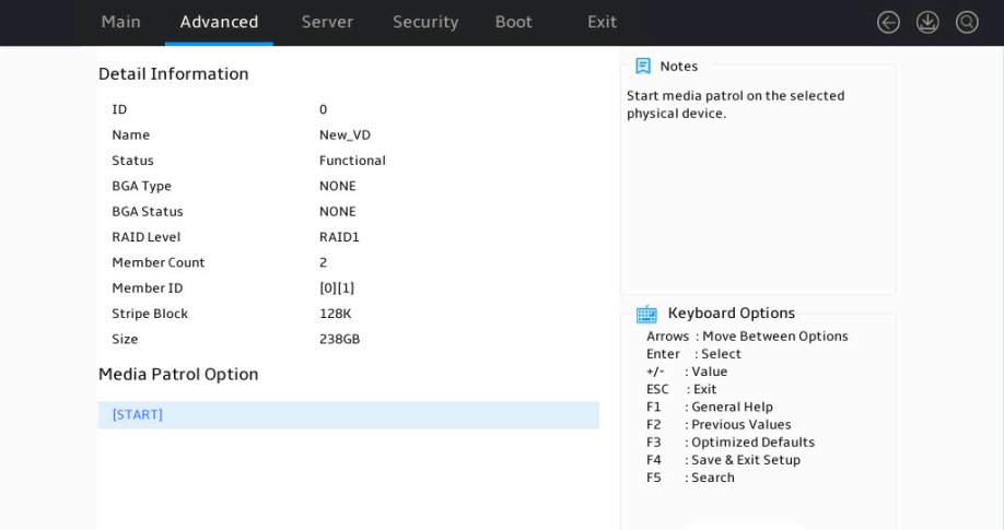
Configuring logical drive media patrol
This feature is available only when RAID 1 is configured.
To configure logical drive media patrol:
1. Access the storage controller configuration screen, select Virtual Device Information, and press Enter.
Figure 17 Storage controller configuration screen

2. Select a target logical drive, and press Enter.
Figure 18 Selecting s logical drive

The logical drive detail screen opens.
3. Select START and press Enter.
Figure 19 Logical drive detail screen

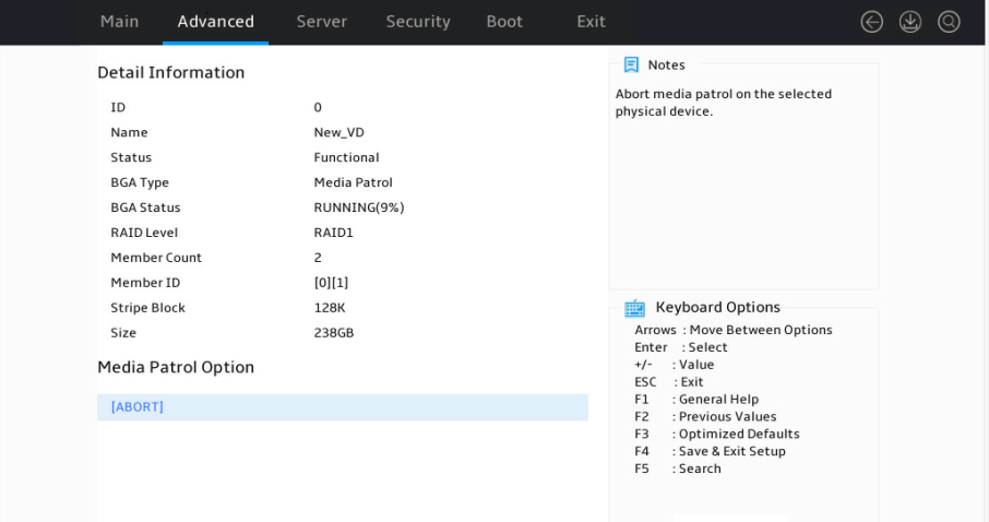
4. Select a target logical drive for media patrol, and press Enter.
Figure 20 Selecting a drive for media patrol
As shown in Figure 21, the media patrol is in progress. To terminate the patrol, select ABORT, and press Enter.
Figure 21 Media patrol in progress
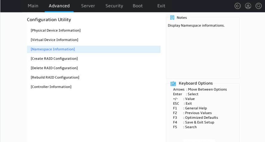
Viewing namespace information
1. Access the storage controller configuration screen, select Namespace Information, and press Enter.
Figure 22 Storage controller configuration screen
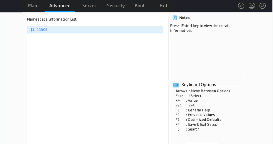
2. Select a logical drive to query its namespace and press Enter.
Figure 23 Selecting a logical drive for viewing its namespace
The namespace information screen opens. Parameters are as described in Table 6.
Figure 24 Logical drive namespace information
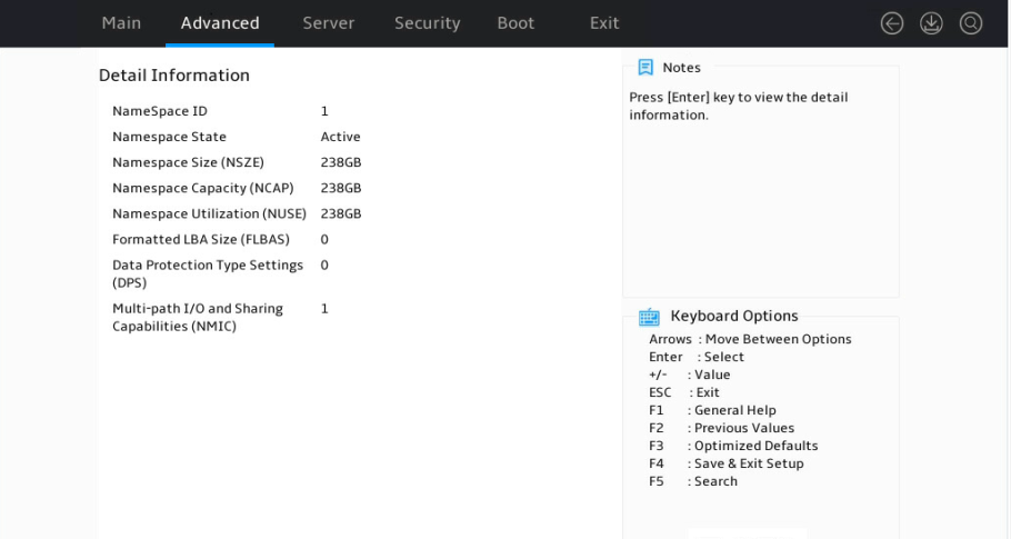
|
Parameter |
Description |
|
NameSpace State |
Namespace states. Options include: · Active. · Inactive. |
|
NameSpace Capacity |
Namespace available capacity. Value in this field usually equals that of the NameSpace Size field. |
|
NameSpace Utilization |
Namesapce capacity that has been used. Value in this field must be no more than that of the Namespace Capacity field. |
|
Formatted LBA Size |
Formatted logical block size. |
|
Data Protection Type Settings |
Enabling status of the data protection feature. Options include: · 0—Disabled. · 1—Enabled. |
|
Multi-path I/O and Sharing Capabilities |
Enabling status of multi-path I/O and sharing namespace: · 0—Disabled. · 1—Enabled. |
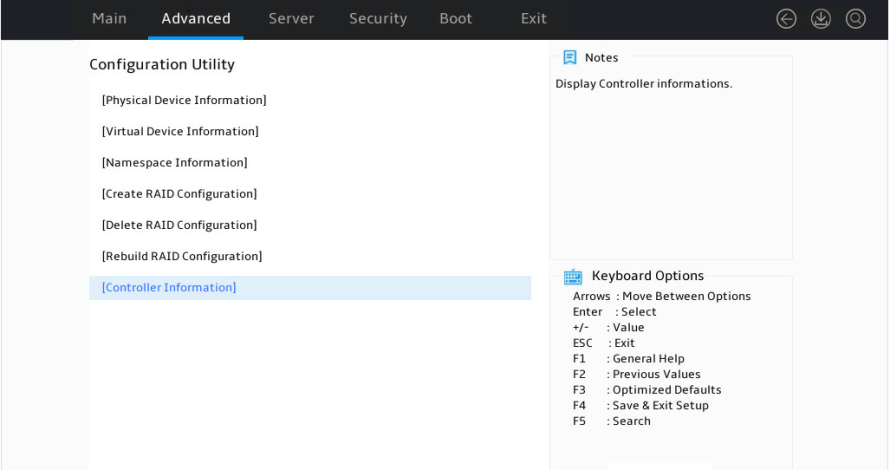
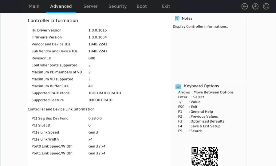
Viewing storage controller information
Access the storage controller configuration screen, select Controller Information, and press Enter.
Figure 25 Storage controller configuration screen
The storage controller information screen opens.
Figure 26 Storage controller information
Configuring RAID in OS
Viewing information
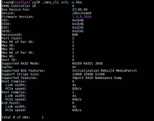
Viewing information about the host bus adapter
Syntax
./mnv_cli info -o hba
Examples
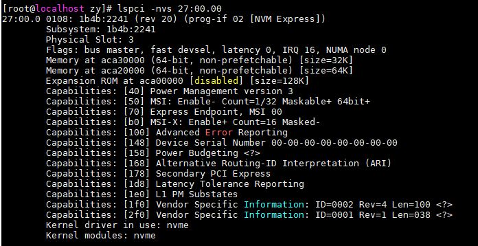
Viewing server component information
Syntax
lspci -nvs bus:device:function
Parameters
|
Parameter |
Description |
Value |
|
bus:device:function |
Specifies a component in a system by its bus, device, and function IDs. |
N/A |
Examples
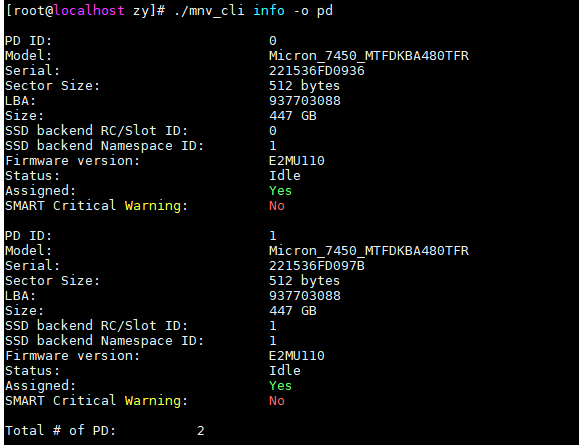
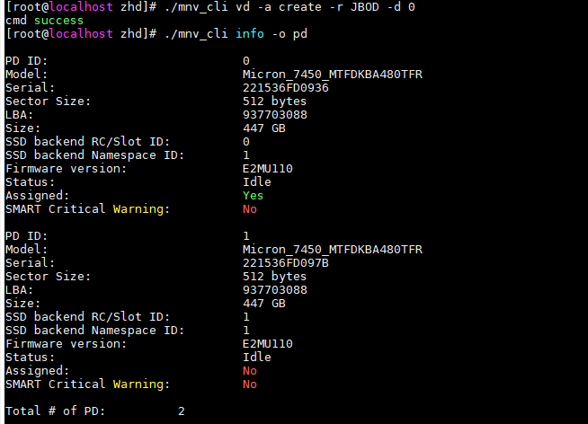
Viewing physical drive informatoin
Syntax
./mnv_cli info -o pd
Examples
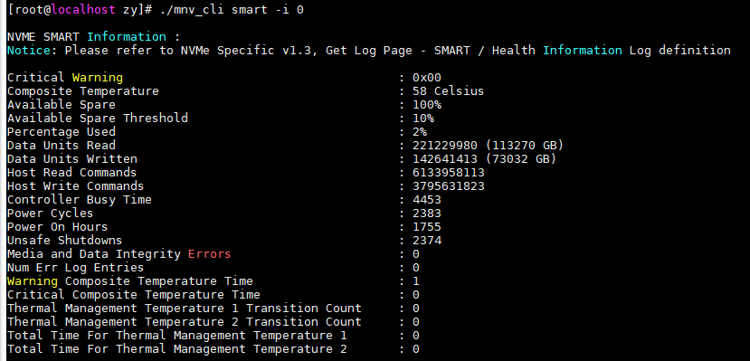
Viewing the smart information of a drive
Syntax
./mnv_cli smart -i pd_id
Parameters
|
Parameter |
Description |
Valne |
|
pd id |
Drive ID. |
0 or 1 |
Examples
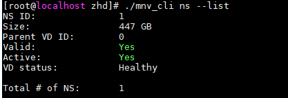
Viewing namespace information
Syntax
./mnv_cli ns --list
Examples
Retrieving the primary controller ID
Syntax
./mnv_cli ns -p ctrl
Examples
![]()
Configuring RAID
Creating RAID
Syntax
./mnv_cli vd –a create –r raid_level -d pd_id [ -b stripe size ]
Parameters
|
Parameter |
Description |
Value range |
|
raid level |
RAID level |
0, 1, and JBOD |
|
pd id |
Drive ID |
0 and 1 |
|
stripe size |
Stripe size |
128, 256, and 512 |
Examples
![]()
Creating JBOD
Syntax
./mnv_cli vd -a create -r JBOD -d pd id
Parameters
|
Parameter |
Description |
Value range |
|
pd id |
Drive ID |
0 and 1 |
Examples
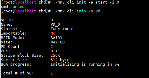
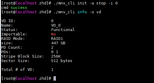
Initializing a logical drive
Syntax
./mnv_cli init -a < start | stop > -i vd id
Parameters
|
Parameter |
Description |
Value range |
|
start | stop |
· Start: Starts logical drive initialization. · Stop: Stops logical drive initialization. |
N/A |
|
vd id |
Logical drive ID. |
0 to N |
Examples
Starting media patrol on a logical drive
Syntax
./mnv_cli mp -a < start | stop > -i vd_id
Parameters
|
Parameter |
Description |
Value range |
|
start | stop |
· Start: Starts media patrol on a logical drive. · Stop: Stops media patrol on a logical drive |
N/A |
|
vd id |
Logical drive id |
0 to N |
Examples
![]()
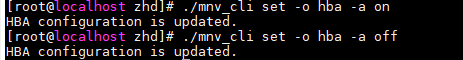
Rebuilding RAID automatically
Syntax
./mnv_cli set -o hba -a < on | off >
Parameters
|
Parameter |
Description |
Values |
|
on | off |
on: Enables auto RAID rebuilding. off: Disables auto RAID rebuilding. |
N/A |
Examples
Importing a logical drive
Syntax
./mnv_cli import -l vd id
Parameters
|
Parameter |
Description |
Value range |
|
vd id |
Logical drive ID |
0 to N |
Examples

Locating the LED
Syntax
./mnv_cli led -o rc -i pd id -a sb
Parameters
|
Parameter |
Description |
Value range |
|
pd id |
Drive ID. |
0 and 1 |
Examples
![]()
Viewing logs
Enabling or disabling logging
Syntax
./mnv_cli log -a < on | off >
Parameters
|
Parameter |
Description |
Value range |
|
on | off |
on: Enables logging. off: Disables logging. |
N/A |
Examples
![]()
Viewing and saving logs
Syntax
./mnv_cli log -a show --outputfile=log.txt
Examples
![]()
Displaying all storage controller events
Syntax
./mnv_cli event -c n
Parameters
|
Parameter |
Description |
Value range |
|
n |
Specifies the Nth storage controller. This command displays logs about all storage controllers when N is 0. |
0 to N |
Upgrading firmware
Displaying the firmware version
Syntax
./mnv.cli info -o hba
Examples

Upgrading firmware
Syntax
./mnv_cli flash -o hba -t raw -f raw.bin
Parameters
|
Parameter |
Description |
Value range |
|
raw.bin |
Specifies the firmware file for the Marvell storage controller. |
N/A |
Examples
![]()
Troubleshooting
For detailed information about collecting storage controller fault information, diagnosing and locating faults, and troubleshooting servers, see H3C Servers Troubleshooting Guide.
Compatibility
For information about storage controller and server compatibility, access http://www.h3c.com/en/home/qr/default.htm?id=66.
