- Table of Contents
-
- H3C G6 Servers Storage Controller User Guide-6W103
- 00-Preface
- 01-Storage controller overview
- 02-Storage controller features
- 03-Configuring a VROC SATA RAID controller
- 04-Configuring an NVMe VROC module
- 05-Configuring an LSI-9540 or 9560 storage controller
- 06-Configuring an LSI-9660 series storage controller
- 07-Configuring a P460, P2404 or P4408 storage controller
- 08-Configuring an LSI 9500 series storage controller
- 09-Configuring a RAID-MARVELL-SANTACRUZ-LP-2i storage controller
- 10-Configuring a RAID-MARVELL-M.2 storage controller
- 21-Appendix A Troubleshooting storage controllers
- 22-Appendix B RAID arrays and fault tolerance
- Related Documents
-
| Title | Size | Download |
|---|---|---|
| 04-Configuring an NVMe VROC module | 4.11 MB |
Configuring an NVMe VROC module
|
|
NOTE: The BIOS screens might vary by the BIOS version. The screenshots in this chapter are for illustration only. |
This chapter describes configuring the NVMe VROC module on a rack server, blade server, or compute module.
About the NVMe VROC module
Intel® Virtual RAID on CPU (Intel® VROC) is an upper-layer RAID solution specifically designed for NVMe drives that are directly connected to the CPU. VROC NVMe RAID is available only when an NVMe VROC module is installed.
The NVMe VROC module has a corresponding connector on the system board or main board. For more information about the NVMe VROC module connector, see the user guide for the server.
The NVMe VROC module can manage NVMe U.2 SSDs and NVMe M.2 SSDs connected to the system board or main board. If NVMe M.2 SSDs are connected to a storage controller, the NVMe M.2 SSDs are managed exclusively by the controller.
Features
NVMe VROC module specifications
Table 1 shows the specifications of NVMe VROC modules supported by the server. For more information, contact Technical Support.
Table 1 NVMe VROC module specifications
|
Model |
Description |
Upgrade Key |
RAID levels |
|
N/A |
No NVMe VROC module installed |
VROC in pass-thru mode |
· Intel NVMe drives P3608, P4608, and P4618: RAID 0. · Other NVMe drives: RAID not supported. Each drive acts as a passthrough drive. NOTE: Intel NVMe drives P3608, P4608, and P4618 are not supported by H3C servers. |
|
NVMe-VROC-Key-i |
Intel® VROC Intel® Edition |
Intel |
· Intel NVMe drives: 0, 1, 5, 10 · Other NVMe drives: RAID not supported. Each drive acts as a passthrough drive. |
|
NVMe-VROC-Key-S |
Intel® VROC Standard Edition |
Standard |
0, 1, 10 |
|
NVMe-VROC-Key-P |
Intel® VROC Premium Edition |
Premiere |
0, 1, 5, 10 |
|
|
NOTE: An upgrade key represents the NVMe VROC key displayed on the BIOS screen. |
RAID levels
The supported RAID levels vary by NVMe VROC module model. For more information, see H3C Servers Storage Controllers Technical Specifications.
Table 2 shows the minimum number of drives required by each RAID level and the maximum number of failed drives supported by each RAID level. For more information about RAID levels, see "Appendix B RAID arrays and fault tolerance."
Table 2 RAID levels and the numbers of drives for each RAID level
|
RAID level |
Min. drives required |
Max. failed drives |
|
RAID 0 |
2 |
0 |
|
RAID 1 |
2 |
1 |
|
RAID 5 |
3 |
1 |
|
RAID 10 |
4 |
n, where n is the number of RAID 1 arrays in the RAID 10 array. |
Restrictions and guidelines for RAID configuration
· As a best practice, install drives that do not contain RAID information.
· For efficient use of storage, use drives that have the same capacity to build a RAID. If the drives have different capacities, the lowest capacity is used across all drives in the RAID.
· If one drive is used by several logical drives, RAID performance might be affected and maintenance complexities will increase.
· To use VROC (NVMe RAID), the system has specific requirements on the VMware operating system. For more information, access http://www.h3c.com/cn/home/qr/default.htm?id=367.
Configuring RAID arrays in UEFI mode
This section describes how to configure RAID arrays through an embedded RSTe RAID controller in UEFI mode. For more information about how to enter the BIOS and set the boot mode to UEFI, see the BIOS user guide for the server.
RAID array configuration tasks at a glance
To configure RAID arrays in UEFI mode, perform the following tasks:
· Accessing NVMe RAID configuration screen
· (Optional.) Configuring a hot spare drive
· (Optional.) Deleting RAID arrays
Configuring VMD settings
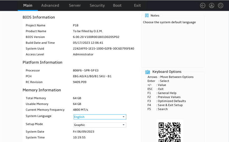
1. During server POST, press Delete, Esc, or F2 as prompted to open the BIOS setup screen as shown in Figure 1.
For how to navigate screens and modify settings, see the operation instructions at the lower right corner.
Figure 1 BIOS setup screen
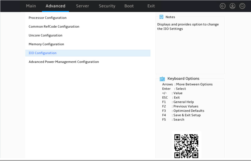
2. On the screen as shown in Figure 2, select Advanced > Socket Configuration > IIO Configuration, and press Enter.
Figure 2 Socket Configuration screen
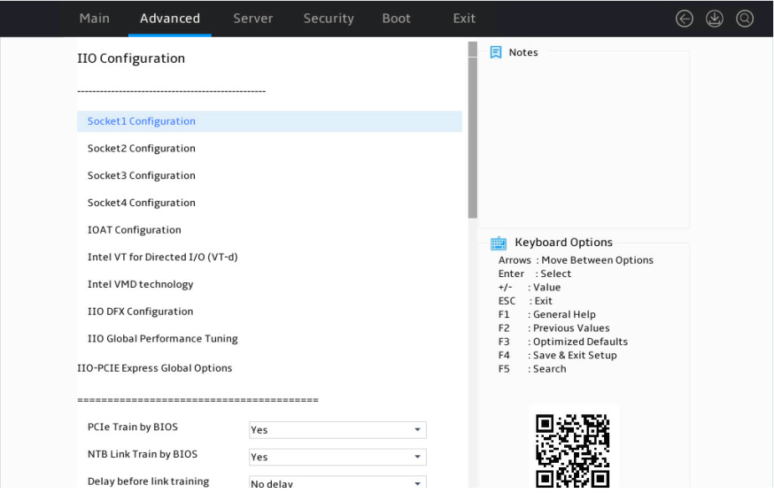
3. On the screen as shown in Figure 3, select Intel VMD technology, and then press Enter.
Figure 3 IIO Configuration screen
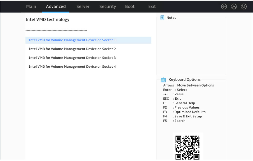
4. On the screen as shown in Figure 4, select Intel® VMD for Volume Management Device on Processor 1, and then press Enter.
This section takes processor 1 as an example.
Figure 4 Intel® VMD technology screen
5. On the screen as shown in Figure 5, set the VMD port XX-Slot XX item in each VMD Config for IOU X field to Auto, and then press Enter.
To use NVMe drives attached to a processor for RAID configuration, set VMD status for that processor to Enabled.
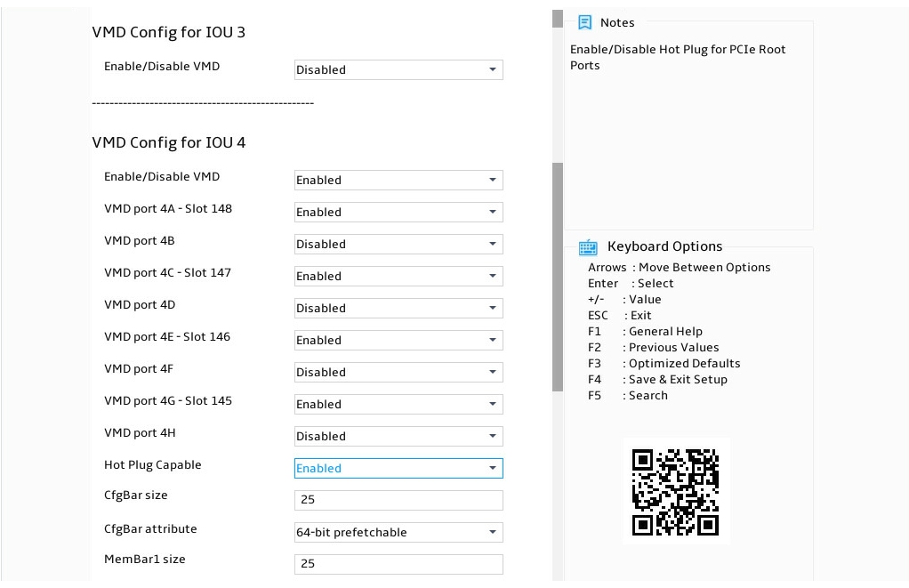
Table 3 Configuration parameters
|
Parameter |
Description |
Default |
|
VMD Config for PCH (IOU n) |
Specifies the VMD configuration field for the PCH or IOU n. |
N/A |
|
Enable/Disable VMD |
Select Enabled or Disabled to enable or disable VMD for the PCH or IOU. This feature is available only in UEFI mode. The following configuration items are displayed only when VMD is enabled. |
Disabled |
|
VMD port nA/B/C/D – Slot x |
Select Enabled or Disabled to enable or disable VMD for the port. This field is available for a port only when a device is connected to the port. The slot number varies by riser card and NVMe drive backplane. |
Disabled |
|
Hot Plug Capable |
Select Enabled or Disabled to enable or disable hot swapping for a port. |
Disabled |
|
CfgBar Size |
Set the BAR size in bits. The value range is 20 to 27. |
25 |
|
MemBar1 size |
Set the size of memory bar 1. |
25 |
|
MemBar2 size |
Set the size of memory bar 2. |
20 |
6. For VMD settings to take effect, save the settings and then restart the BIOS.
Accessing NVMe RAID configuration screen
1. Access the BIOS setup screen.
2. Enter the controller management screen.
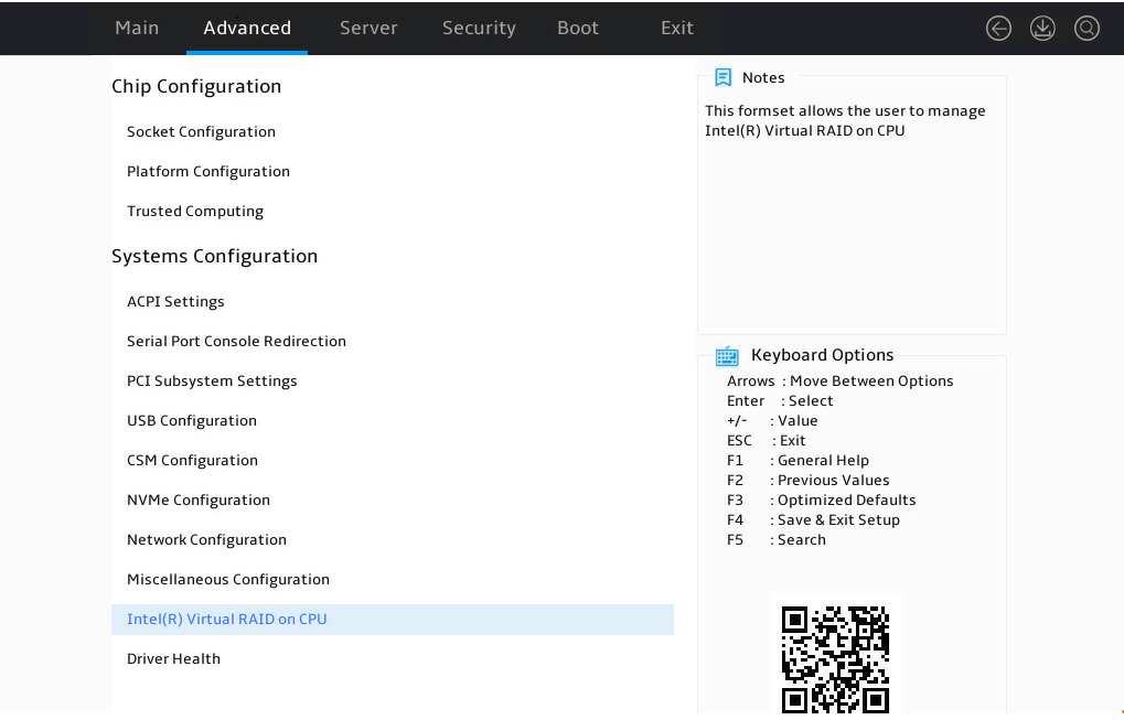
a. On the top navigation bar, click Advanced.
b. Click Dynamic Device Configuration, or proceed to the next step, depending on the BIOS version.
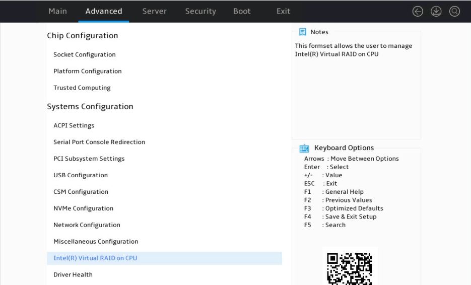
3. Select the target storage controller, for example, Intel® Virtual RAID on CPU, and then press Enter.
|
|
NOTE: For the Intel® Virtual RAID on CPU option to appear on the screen shown in Figure 6, make sure the VMD controllers have been enabled. |
Figure 6 Advanced screen
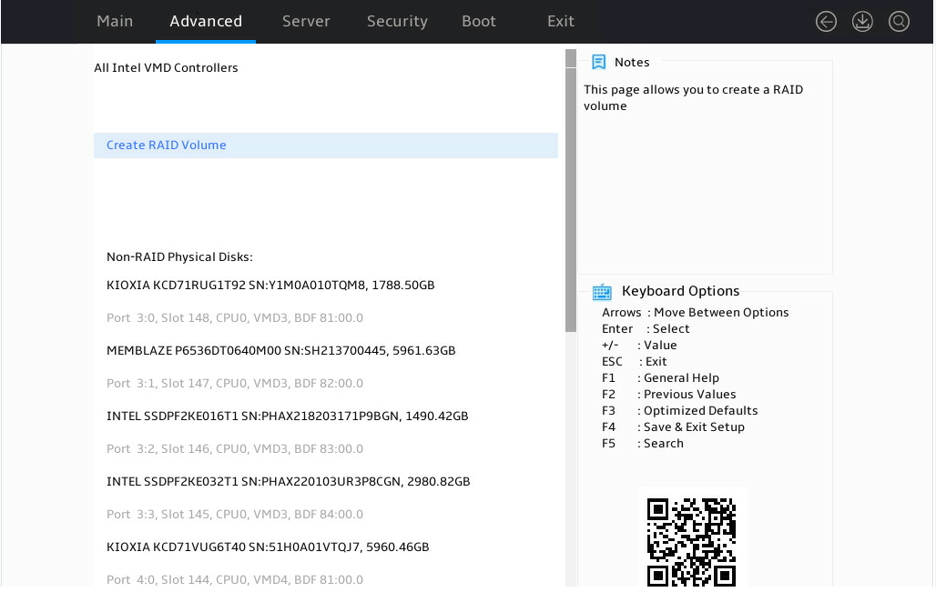
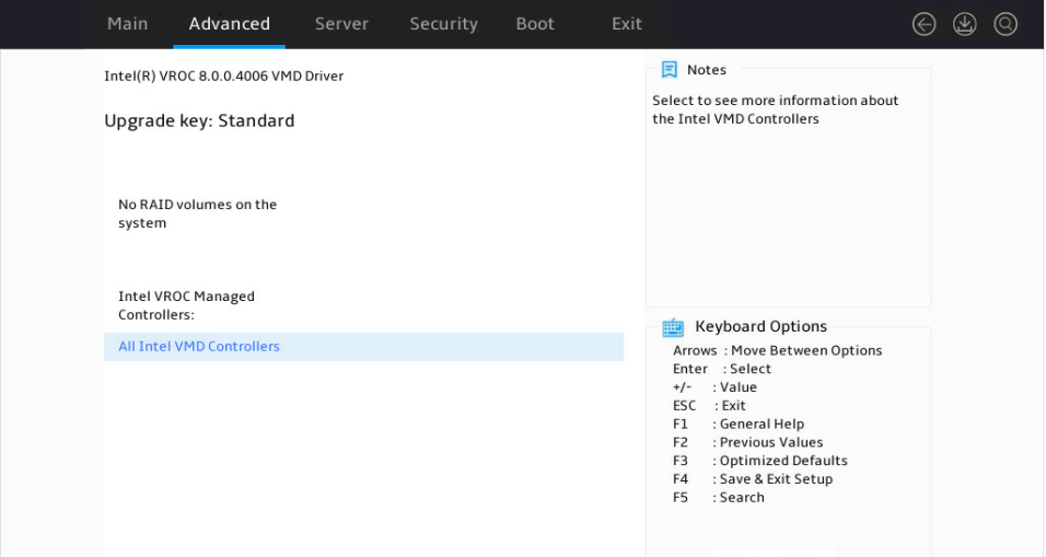
4. On the screen as shown in Figure 7, select All Intel VMD Controllers, and then press Enter.

The RAID configuration screen as shown in Figure 8 opens.
Figure 8 All Intel VMD Controllers screen
Configuring RAID arrays
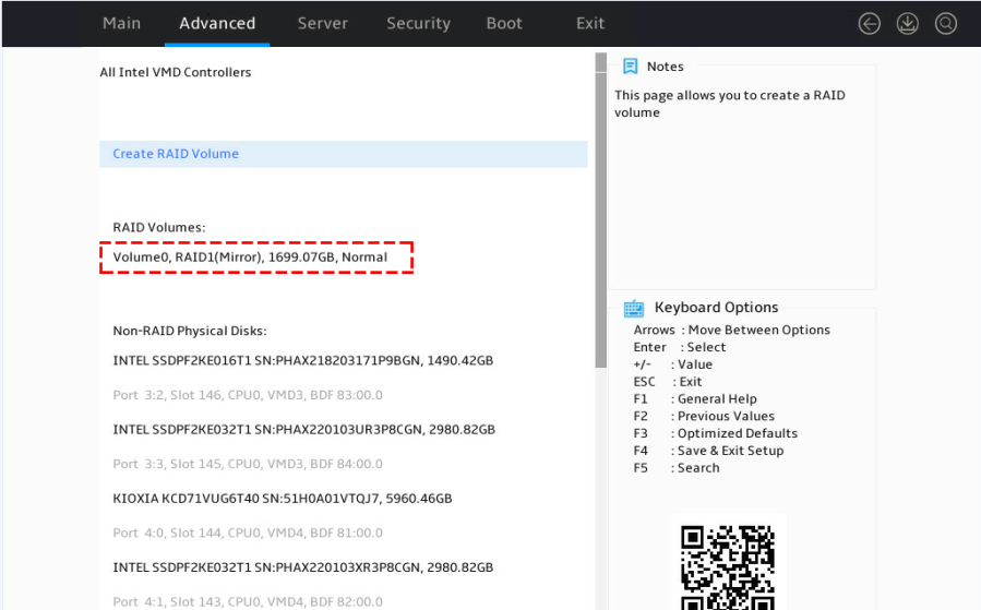
1. On the RAID configuration screen as shown in Figure 9, select Create RAID Volume, and press Enter.
The Create RAID Volume option is available only when the NVMe VROC module identifies that a minimum of two non-RAID NVMe drives are present.
Figure 9 Selecting Create RAID Volume
2. On the screen as shown in Figure 10, set the Name, RAID Level, Select Disks, and Capacity parameters, select Create Volume, press Enter, select Yes, and then press Enter to create the RAID volume.
Table 4 describes the configuration parameters for creating a RAID volume.
Figure 10 Setting RAID parameters

Table 4 Configuration parameters
|
Parameter |
Description |
|
Name |
RAID array name. |
|
RAID Level |
RAID level, which determines the performance, fault tolerance capability, and capacity for the logical drive. |
|
Enable RAID spanned over VMD Controllers |
Press the space bar to configure this item. To build a RAID volume over physical drives controlled by different VMD controllers, select this item. [X] indicates that this item has been selected. |
|
Strip Size |
Stripe size, which determines the size of the data block that can be written into a stripe on each drive. |
|
Select Disks |
Select member drives for the RAID array. Available drives are displayed under Select Disks. Press Enter to select drives. [X] indicates that the corresponding drive has been selected. |
|
Capacity (GB) |
Logical drive capacity. |
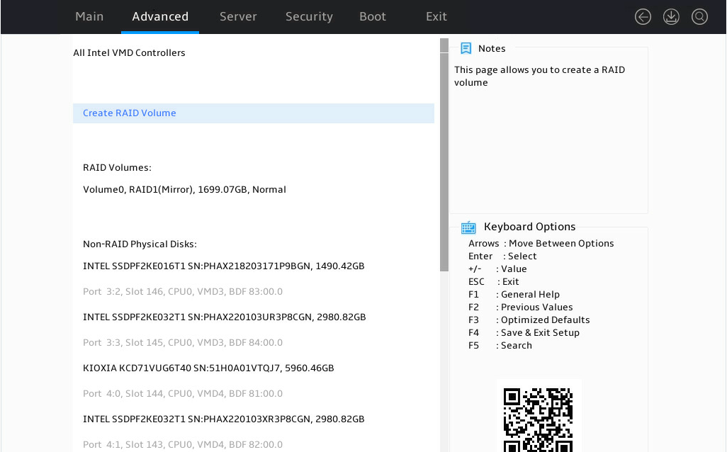
3. The screen as shown in Figure 11 opens.
After the RAID volume is created, the RAID volume is displayed in the RAID Volumes directory. To view details about a RAID volume, select the RAID volume, and press Enter. Details about a RAID volume include the RAID array name, RAID level, strip size, RAID status, RAID capacity, whether the RAID volume is bootable, and member drives.
Figure 11 Viewing the created RAID volume

Configuring a hot spare drive
This task configures a global hot spare drive. The hot spare drive is effective for all created RAID volumes. Multiple hot spare drives can be created to protect multiple RAID volumes.
To configure a hot spare drive:
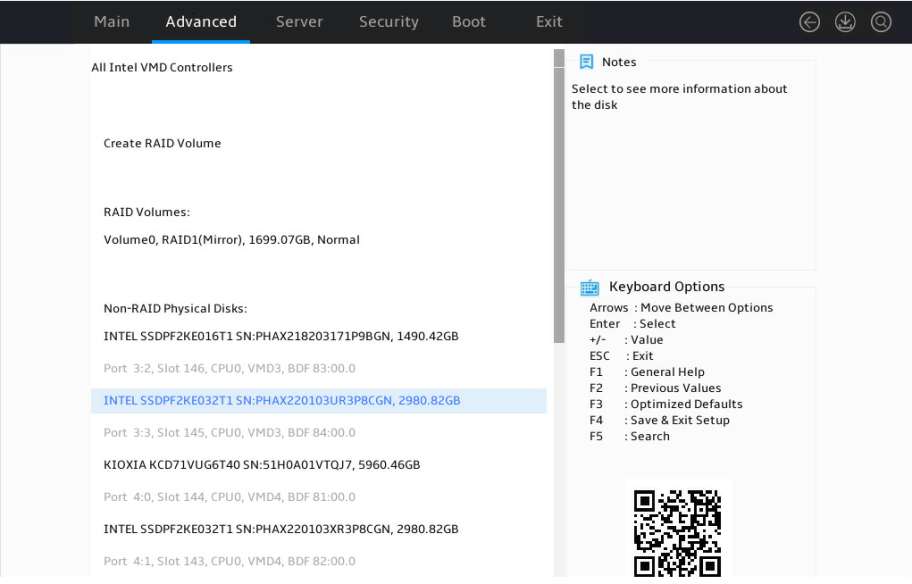
1. On the RAID configuration screen as shown in Figure 12, select the drive to be configured as a spare drive, and press Enter.
Figure 12 Selecting the drive to be configured as a spare drive
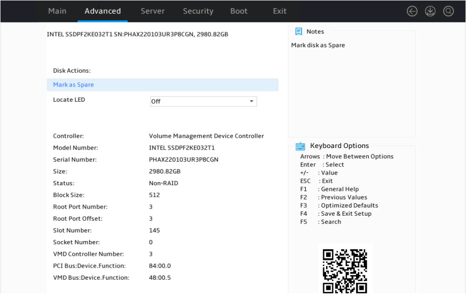
2. On the screen as shown in Figure 13, select Mark as Spare, and press Enter.
Figure 13 Spare drive configuration screen
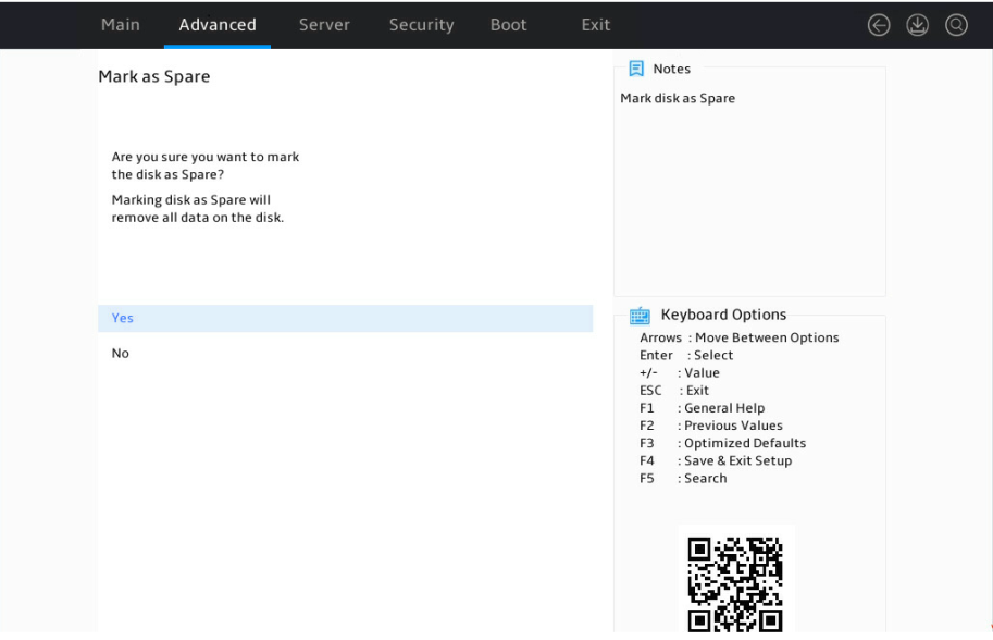
3. On the screen as shown in Figure 14, select Yes, and press Enter.
Figure 14 Confirming the spare drive configuration
Deleting RAID arrays
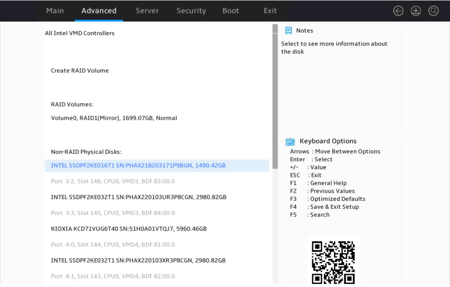
1. On the RAID configuration screen as shown in Figure 15, select the RAID volume to delete under RAID Volumes, and press Enter.
Figure 15 Selecting the RAID volume to be deleted
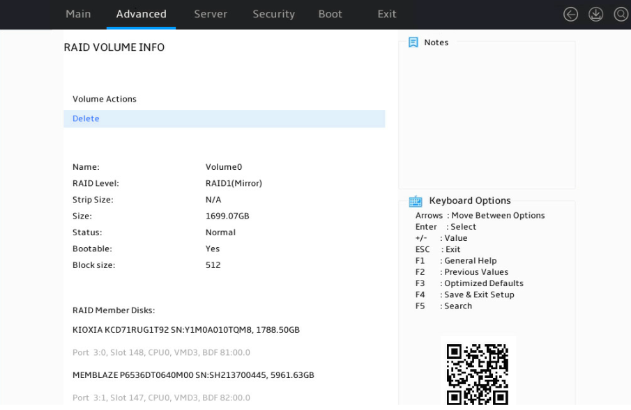
2. On the screen as shown in Figure 16, select Delete and press Enter.
Figure 16 RAID volume information screen
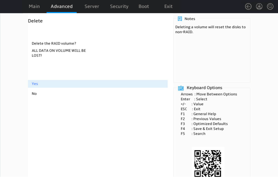
3. On the screen as shown in Figure 14, select Yes, and press Enter.
Figure 17 Confirming the spare drive deletion
Locating an NVMe drive
1. On the RAID configuration screen as shown in Figure 15, select the RAID volume to be located under RAID Volumes, and press Enter.
Figure 18 Selecting the NVMe drive to be located
2. On the screen as shown in Figure 19, select On for the Locate LED On option and press Enter.
Figure 19 Locating the NVMe drive

Viewing NVMe VROC Key specifications
1. Access the BIOS Setup Utility.
2. Access the Advanced > Intel® Virtual RAID on CPU screen.
|
|
NOTE: The Intel® Virtual RAID on CPU item is displayed only when the VMD controller is enabled. For more information about enabling the VMD controller, see "Configuring VMD settings." |
Figure 20 Advanced screen
3. On the NVMe RAID summary screen, view the upgrade key, which represents the NVMe VROC Key specifications. For more information, see "NVMe VROC module specifications."
Figure 21 NVMe RAID summary screen
Configuring RAID arrays in legacy mode
NVMe VROC in legacy mode does not support RAID configuration.
Configuring RAID arrays in Linux
RAID array configuration tasks at a glance
To configure RAID arrays in Linux, perform the following tasks:
· Accessing NVMe RAID configuration screen
· (Optional.) Configuring a hot spare drive
· (Optional.) Deleting RAID arrays
Configuring VMD settings
Configure VMD settings as described in "Configuring VMD settings."
Verifying VMD status
1. Access the CLI of the server.
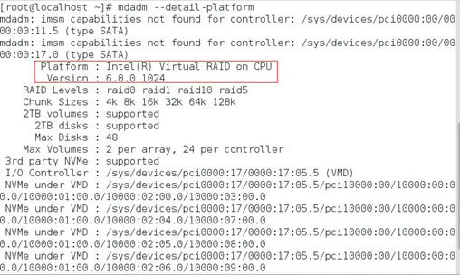
2. Execute the mdadm –-detail-platform command to examine VMD status, as shown in Figure 22:
¡ If the screen displays the Platform and Version fields, it indicates that VMD has been enabled, and the server supports configuring RAID arrays.
¡ If the screen does not display the Platform and Version fields, it indicates VMD has not been enabled. You can set the VMD statues to Auto or Enabled. For information about how to enable VMD for RAID configuration, see "Configuring VMD settings."
|
|
NOTE: The information in the Version field might vary by server model. |
Figure 22 Verifying VMD status
Configuring RAID arrays
Prerequisites
Make sure the number of NVMe drives meets the requirements for RAID configuration. Execute the lsblk command to view the number of NVMe drives, as shown in Figure 23.
Figure 23 Viewing the number of NVMe drives

Procedure
1. Execute the mdadm -C /dev/md/imsm0 /dev/nvme[1-4]n1 -n 4 -e imsm command to create a container, as shown in Figure 24.
Table 5 describes the parameters.
Figure 24 Creating a container
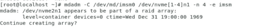
Table 5 Configuration parameters
|
Parameter |
Description |
|
/dev/md/imsm0 |
Container name. |
|
/dev/nvme[1-4]n1 |
NVMe drives to be used for creating the container. |
|
n |
Number of NVMe drives. |
|
-e imsm |
Specify the keyword to enable support of the Intel®Matrix Storage Manager (IMSM) metadata format. |
2. Execute the mdadm -C /dev/md0 /dev/md/imsm0 -n 4 -l 5 -z 10G command to create a container, as shown in Figure 25.
Table 5 describes the parameters.
Figure 25 Creating a RAID array
![]()
Table 6 Configuration parameters
|
Parameter |
Description |
|
/dev/md0 |
RAID array name. |
|
/dev/md/imsm0 |
Container name. |
|
n |
Number of NVMe drives in the RAID array. |
|
l |
RAID level. |
|
z |
RAID capacity. |
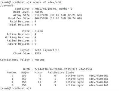
3. Execute the mdadm –D /dev/md0 command to view RAID information, including container name, RAID level, strip size, number of NVMe drives, and RAID status, as shown in Figure 26.
Figure 26 Viewing RAID information
Configuring hot spare drives
Use one of the following methods to configure hot spare drives:
· Configuring hot spare drives while creating a RAID array.
· Configuring hot spare drives after RAID array creation.
Configuring hot spare drives while creating a RAID array
1. Verify that VMD is enabled. For more information, see "Verifying VMD status."
2. Execute the mdadm –C /dev/md0 /dev/nvme[1-3]n1 –n 3 –e imsm command to create a container, as shown in Figure 27. The number of NVMe drives for creating the container is n + 1. This section takes 3 as an example.
Figure 27 Creating a container
![]()
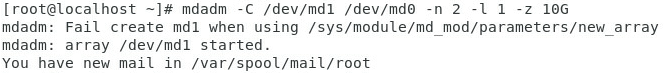
3. Execute the mdadm –C /dev/md1 /dev/md0 –n 2 –l 1 –z 10G command to create a RAID array, as shown in Figure 28. The number of NVMe drives for creating the RAID array is n. This section takes 2 as an example.
Figure 28 Creating a RAID array
Configuring hot spare drives after RAID array creation
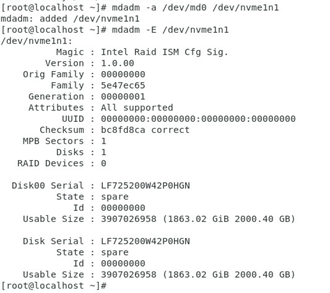
After RAID array creation, execute the mdadm –a /dev/md0 /dev/nvme1n1 command to add hot spare drives to the container.
Figure 29 Configuring hot spare drives
Deleting RAID arrays
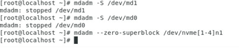
1. Execute the mdadm –S /dev/md1 command to stop the RAID array, as shown in Figure 30.
2. Execute the mdadm –S /dev/md0 command to stop the container, as shown in Figure 30.
3. Execute the mdadm ––zero-superblock /dev/nvme[1-4]n1 command to remove RAID information on NVMe drives, as shown in Figure 30.
Figure 30 Deleting a RAID array
Configuring RAID arrays in Windows
RAID array configuration tasks at a glance
To configure RAID arrays in Windows, perform the following tasks:
· Accessing NVMe RAID configuration screen
· (Optional.) Configuring a hot spare drive
· (Optional.) Deleting RAID arrays
Configuring VMD settings
Configure VMD settings as described in "Configuring VMD settings."
Verifying VMD status
1. Access the CLI of the server.
2. Access Device Manager to examine VMD status:
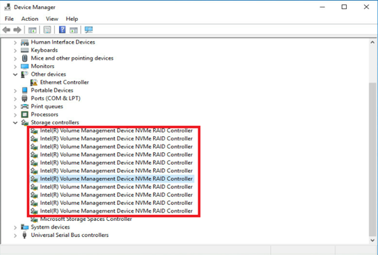
¡ If the screen displays the information in the Storage controllers section as shown in Figure 31, it indicates that VMD has been enabled, and the server supports configuring RAID arrays.
¡ If the screen displays Standard NVM Express Controller or none for NVMe drive information in the Storage controllers section. For information about how to enable VMD for RAID configuration, see "Configuring VMD settings."
Figure 31 Verifying VMD status
Obtaining third-party tools
Access the Intel official website and obtain Intel VROC management tools. This document uses Intel VROC Storage Management Application to configure NVMe RAID arrays as an example.
Configuring RAID arrays
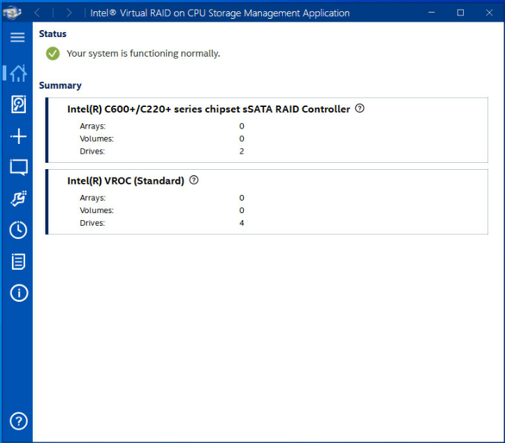
1. Open Intel VROC Storage Management Application, as shown in Figure 32.
Figure 32 Intel VROC Storage Management Application
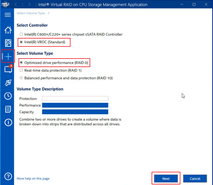
2. Click the + icon, select a controller and a RAID level, and then click Next, as shown in Figure 24.
Figure 33 Selecting a controller and a RAID level
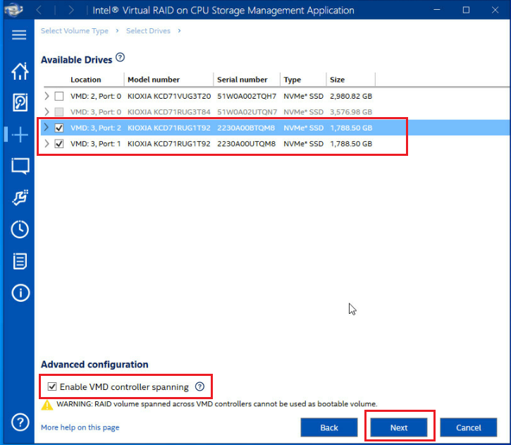
3. Select whether to enable VMD controller spanning and then click Next.
Figure 34 Selecting whether to enable VMD controller spanning
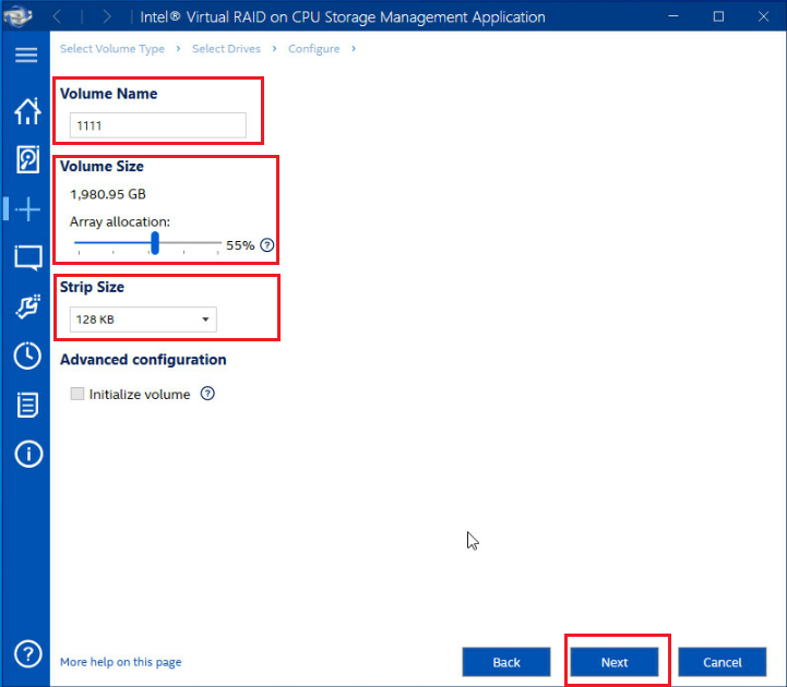
4. As shown in Figure 36, modify the RAID volume name, volume size, and stripe size.
Figure 35 Modifying RAID parameters
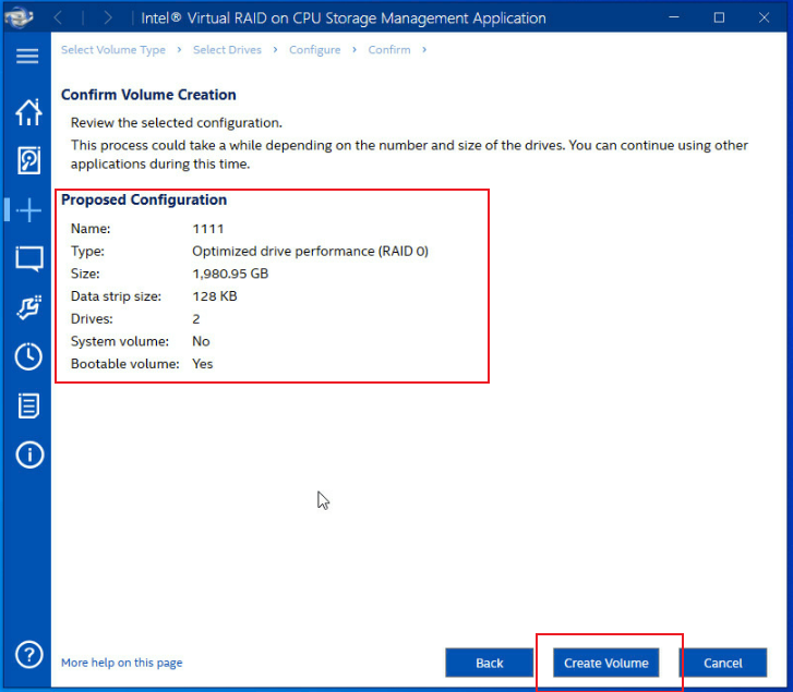
5. Confirm the RAID volume information and then click Create Volume.
Figure 36 Confirming RAID creation
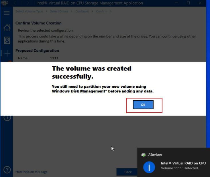
6. Click OK to complete the RAID creation.
Figure 37 Completing RAID creation
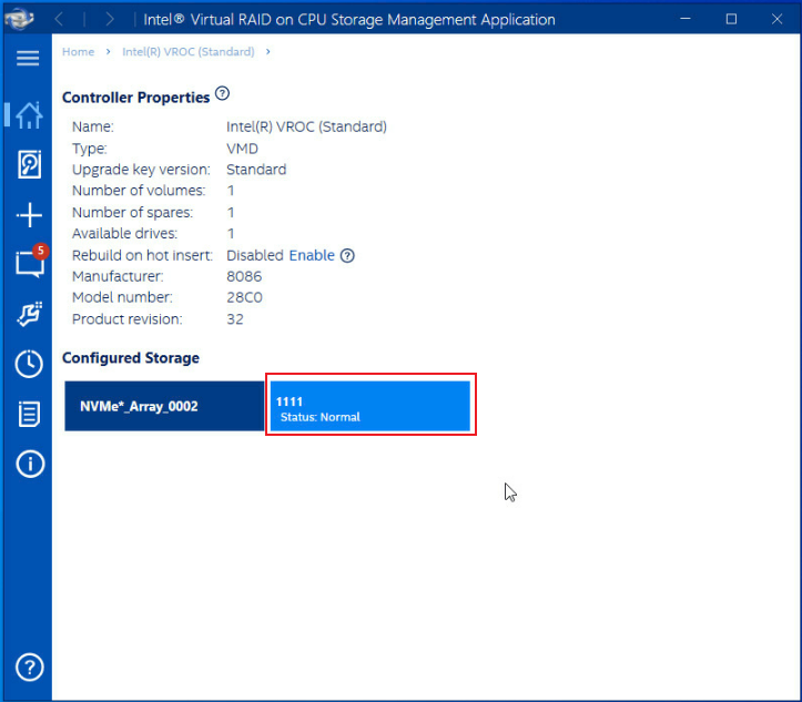
The screen as shown in Figure 39 opens.
After the RAID volume is created, the RAID volume is displayed in the Volumes section. To view details about a RAID volume, click the RAID volume.
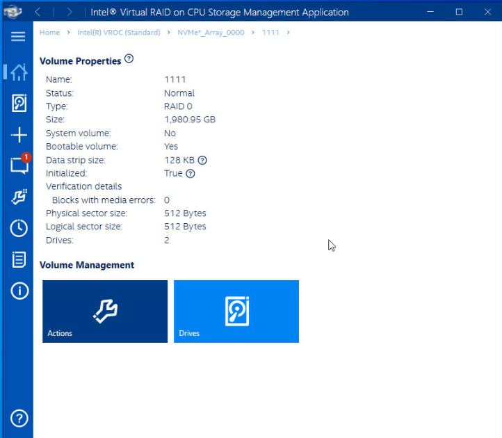
Figure 38 Viewing the created RAID volume
As shown in Figure 39, the page displays detailed RAID information, including the RAID level, strip size, NVMe drives, and RAID status information.
Configuring a hot spare drive
1. Open Intel VROC Storage Management Application.
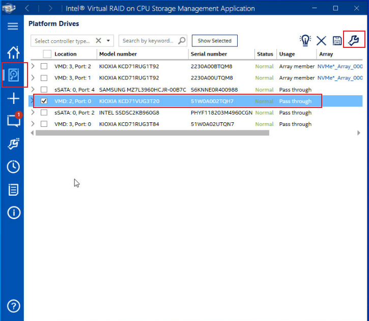
2. Select the NVMe drive to be configured as the hot spare drive from the list, and then click the wrench icon in the upper right corner, as shown in Figure 40.
Figure 40 Configuring a hot spare drive
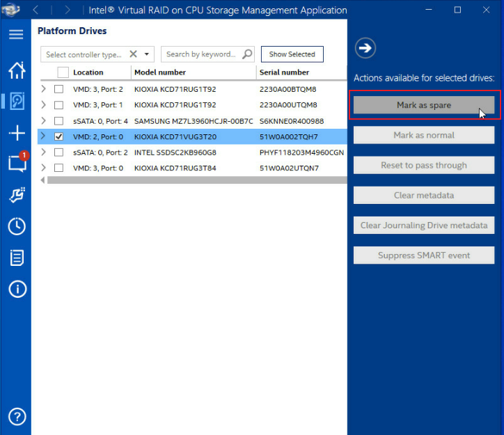
3. As shown in Figure 41, click Mark as spare to set the selected drive as a hot spare drive.
Figure 41 Setting the selected drive as a hot spare drive
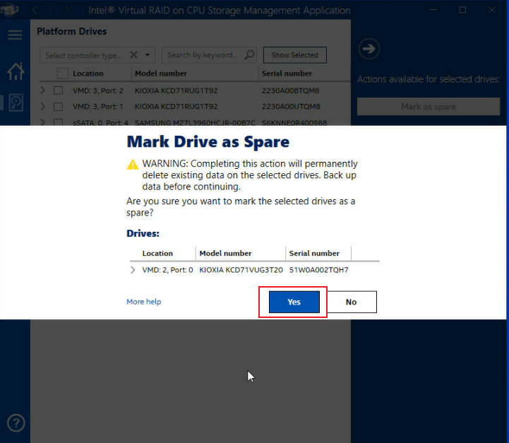
4. In the dialog box that opens, click Yes.
Figure 42 Confirming the configuration
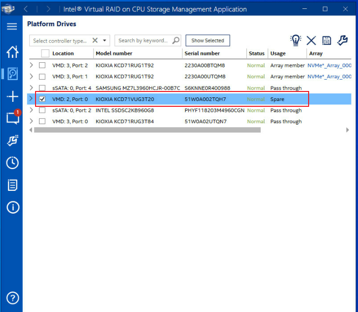
5. Select the NVMe drive and verify that the drive has been configured as a hot spare drive successfully in the Disk Properties section, as shown in Figure 43.
Figure 43 Verifying the configuration
Deleting RAID arrays
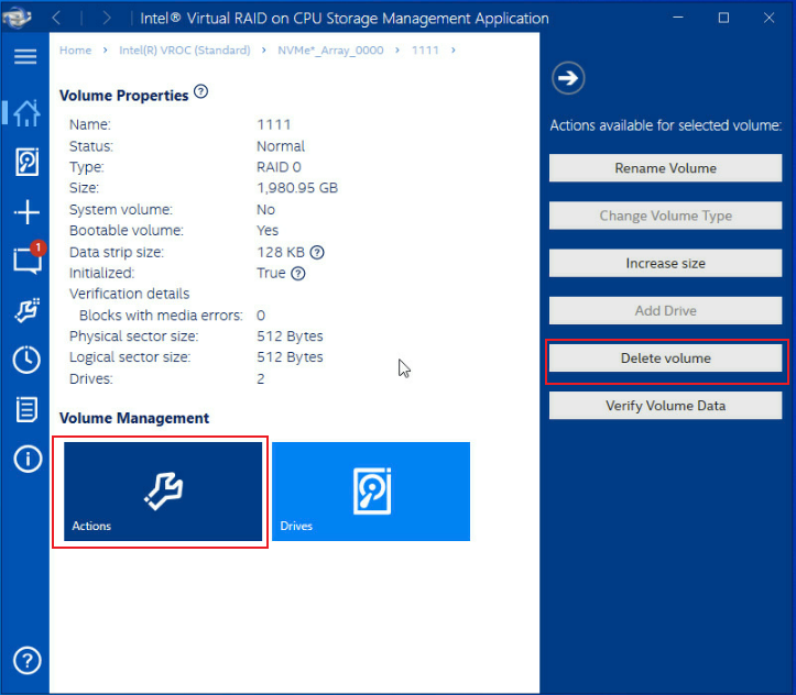
1. Open Intel VROC Storage Management Application.
2. Select the RAID array to be deleted, and then click Delete volume, as shown in Figure 44.
Figure 44 Deleting a RAID array
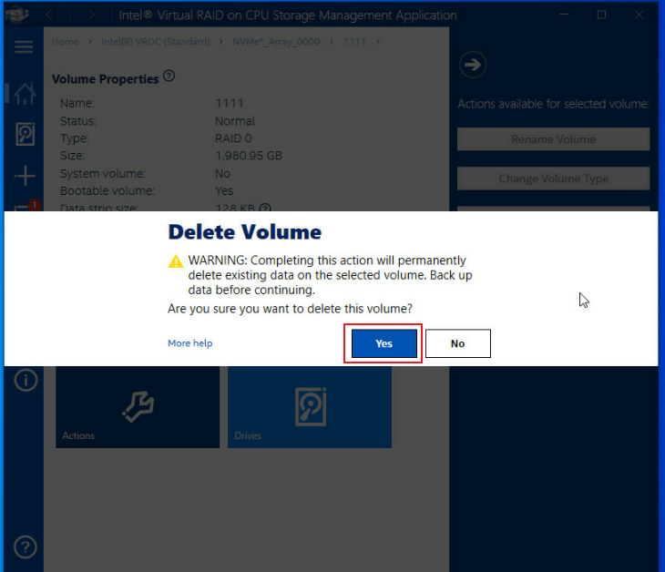
3. In the dialog box that opens, click Yes, as shown in Figure 45.
Figure 45 Confirming the deletion
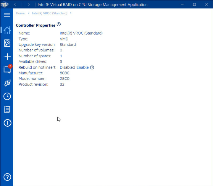
4. Verifying that the RAID array has been deleted by viewing the Volumes list, as shown in Figure 46.
Figure 46 Verifying the deletion
Troubleshooting
For detailed information about collecting storage controller fault information, diagnosing and locating faults, and troubleshooting servers, see H3C Servers Troubleshooting Guide.
Compatibility
For information about storage controller and server compatibility, access http://www.h3c.com/en/home/qr/default.htm?id=66.
Downloading and installing drivers
Access https://www.h3c.com/en/Support/Resource_Center/EN/Severs/Catalog/Optional_Parts/Storage_Controller/?tbox=Software to download the storage controller drivers. For more information about installing drivers, see the release notes for the driver program.
