- Table of Contents
-
- H3C G6 Servers Storage Controller User Guide-6W103
- 00-Preface
- 01-Storage controller overview
- 02-Storage controller features
- 03-Configuring a VROC SATA RAID controller
- 04-Configuring an NVMe VROC module
- 05-Configuring an LSI-9540 or 9560 storage controller
- 06-Configuring an LSI-9660 series storage controller
- 07-Configuring a P460, P2404 or P4408 storage controller
- 08-Configuring an LSI 9500 series storage controller
- 09-Configuring a RAID-MARVELL-SANTACRUZ-LP-2i storage controller
- 10-Configuring a RAID-MARVELL-M.2 storage controller
- 21-Appendix A Troubleshooting storage controllers
- 22-Appendix B RAID arrays and fault tolerance
- Related Documents
-
| Title | Size | Download |
|---|---|---|
| 07-Configuring a P460, P2404 or P4408 storage controller | 18.49 MB |
Configuring an H460, P460, P2404, or P4408 series storage controller
|
|
NOTE: The BIOS screens might vary by the BIOS version. The screenshots in this chapter are for illustration only. |
About H460, P460, P2404, and P4408 storage controllers
The storage controllers support 12-Gbps data channels. Some storage controllers support caching, which greatly improves performance and data security. For more information, access http://www.h3c.com/en/home/qr/default.htm?id=66.
This chapter is available for the following storage controllers:
· HBA-H460-B1
· RAID-P460-B2
· RAID-P460-B4
· RAID-P2404-Mf-4i
· RAID-P4408-Mr-8i-2GB
· RAID-P4408-Ma-8i-2GB
Features
Operating modes
The storage controller supports the following operating modes:
· HBA mode—In this mode, physical drives attached to the storage controller are exposed as raw drives and RAID functions are disabled.
· RAID mode—In this mode, RAID functions are enabled and RAID arrays can be created on physical drives. Only logical drives are exposed to the operating system.
· Mixed mode—This is the default mode. In this mode, RAID functions are enabled and RAID arrays can be created on physical drives. Both logical drives and raw physical drives are exposed to the operating system.
|
|
IMPORTANT: · If the storage controller has RAID configuration, you must clear RAID configuration before changing the operation mode of the storage controller to HBA mode. The new operating mode takes effect after the server reboots. · For the new mode to take effect, restart the server after an operating mode change. · The operating system might fail to start up after the operating mode of the storage controller is changed. To resolve this issue, reinstall the operating system. If the issue persists, contact Technical Support. |
RAID levels
The supported RAID levels vary by storage controller model. For more information about the supported RAID levels of each storage controller, access http://www.h3c.com/en/home/qr/default.htm?id=66.
Table 1 shows the minimum number of drives required by each RAID level and the maximum number of failed drives supported by each RAID level. For more information about RAID levels, see "Appendix B RAID arrays and fault tolerance."
Table 1 RAID levels and the numbers of drives for each RAID level
|
RAID level |
Min. drives required |
Max. failed drives |
|
RAID 0 |
1 |
0 |
|
RAID 1 |
2 |
1 |
|
RAID 1 ADM |
3 |
2 |
|
RAID 5 |
3 |
1 |
|
RAID 6 |
4 |
2 |
|
RAID 10 |
4 |
n, where n is the number of RAID 1 arrays in the RAID 10 array. |
|
RAID 10 ADM |
6 |
2n, where n is the number of RAID 1 ADMs in the RAID 10 ADMs. |
|
RAID 50 |
6 |
n, where n is the number of RAID 5 arrays in the RAID 50 array. |
|
RAID 60 |
8 |
2n, where n is the number of RAID 6 arrays in the RAID 60 array. |
Hot spare drives
You can configure hot spare drives to improve data security. A hot spare drive is a standby drive that does not store any data. When one or multiple drives in a redundant RAID fail, spare drives automatically replace the failed drives and rebuild the data of the failed drives.
The storage controller supports the following types of hot spare drives. For more information about hot spare drive types, see "Storage controller features."
· Dedicated spare drive.
· Auto replace spare drive.
Drive states
Before using a RAID controller to configure RAID and hot spare drives, you must first initialize drives in a raw state. Initializing a drive erases all data on the drive and creates a small partition to store RAID information. Deinitializing a drive removes all data (including metadata) and the reserved space, and removes system partitions, effectively returning the drive to raw state.
Drive states include the following:
· Raw (pass through)—Represents a new or uninitialized drive. The operating system disk management interface can recognize and configure partitions on this disk, making it suitable for OS installation.
· Ready—Indicates that the physical drive has been initialized and can be used to create RAID arrays or set up hot spare drives. The disk management interface of the operating system cannot recognize this state, and the drive cannot be used for system installation.
· Optimal—Indicates that the physical drive is a member of a RAID array.
Setting the RAID controller's working mode to HBA automatically changes the drive state to Raw, and setting the RAID controller's working mode to RAID/Mixed changes the drive state to Ready.
Restrictions and guidelines for RAID configuration
As a best practice, install drives that do not contain RAID information.
To avoid degraded RAID performance or RAID creation failures, make sure all drives in the RAID are the same type (HDDs or SSDs) and have the same connector type (SAS or SATA).
For efficient use of storage, use drives that have the same capacity to build a RAID. If the drives have different capacities, the lowest capacity is used across all drives in the RAID.
If one drive is used by several logical drives, RAID performance might be affected and maintenance complexities will increase.
Configuring RAID arrays in UEFI mode
This section describes how to configure RAID arrays through a storage controller in UEFI mode. For more information about how to enter the BIOS and set the boot mode to UEFI, see the BIOS user guide for the server.
RAID array configuration tasks at a glance
To configure RAID arrays in UEFI mode, perform the following tasks:
· Accessing the storage controller configuration screen
· Switching the operating mode
· (Optional.) Configuring hot spare drives
· (Optional.) Deleting a RAID array
· (Optional.) Viewing drive information
· (Optional.) Locating drives
· (Optional.) Erasing drives
· (Optional.) Modifying storage controller settings
· (Optional.) Clearing storage controller configuration information
· (Optional.) Upgrading the storage controller firmware online
Accessing the storage controller configuration screen
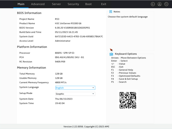
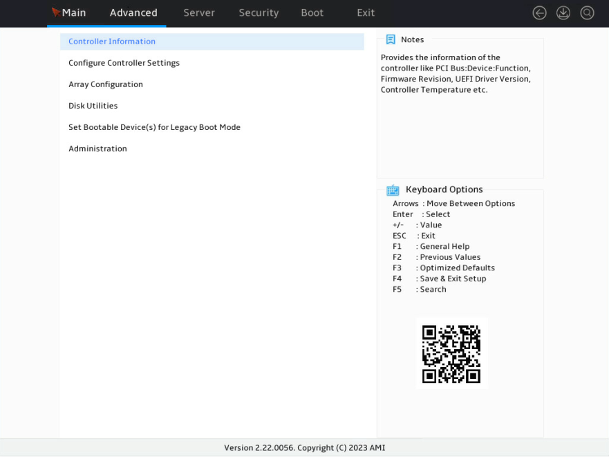
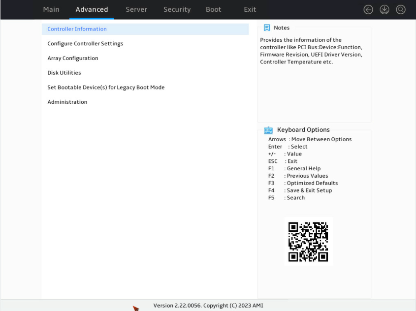
1. Access the BIOS. Press Delete, Esc, or F2 as prompted during server POST to open the BIOS setup screen as shown in Figure 1. For some servers, the Front Page screen opens, and you must select Device Management before proceeding to the next step.
For how to navigate screens and modify settings, see the operation instructions at the lower right corner.
2. Enter the controller management screen.
a. On the top navigation bar, click Advanced.
b. Click Dynamic Device Configuration or UEFI HII Configuration, or proceed to the next step, depending on the BIOS version.
c. Select the target storage controller and then press Enter. In this example, the storage controller model is UN RAID P460-B2.
Switching the operating mode
If RAID arrays have been created, delete all the RAID arrays before you switch the mode.
To switch the operating mode:
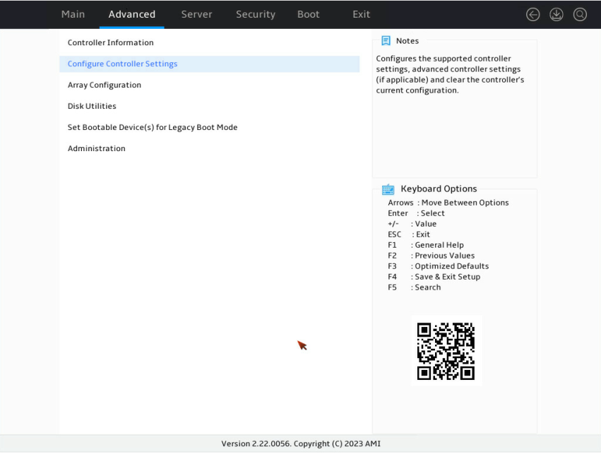
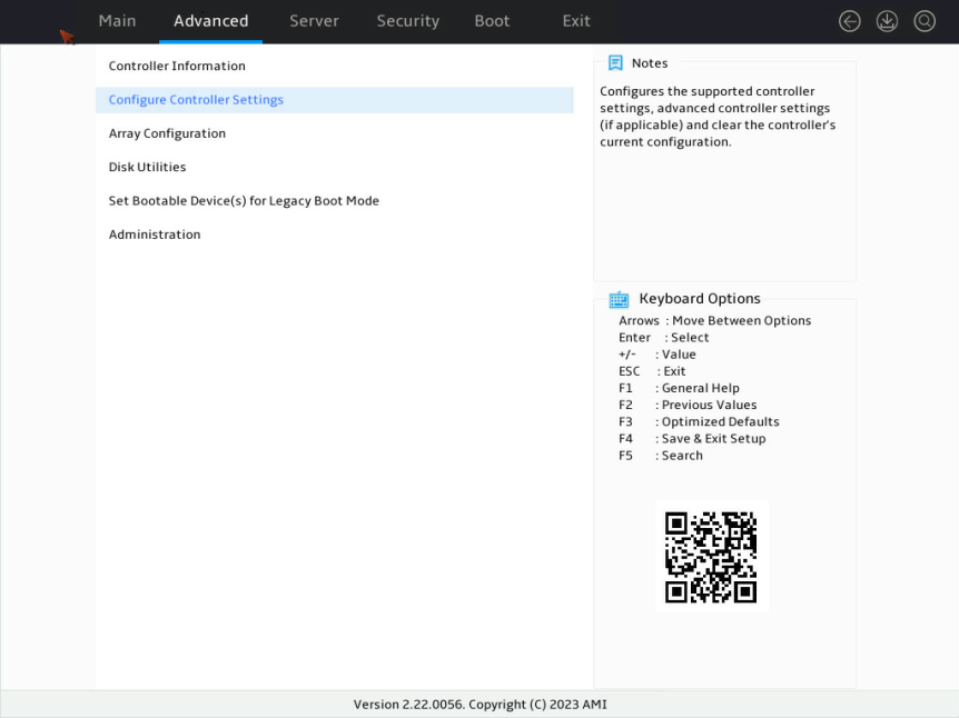
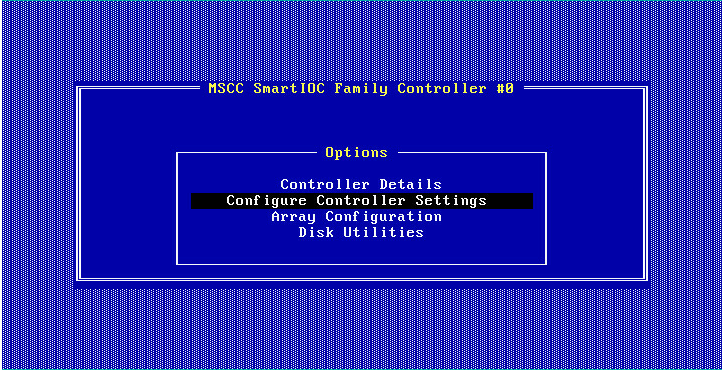
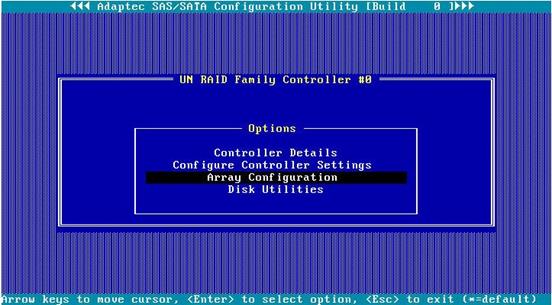
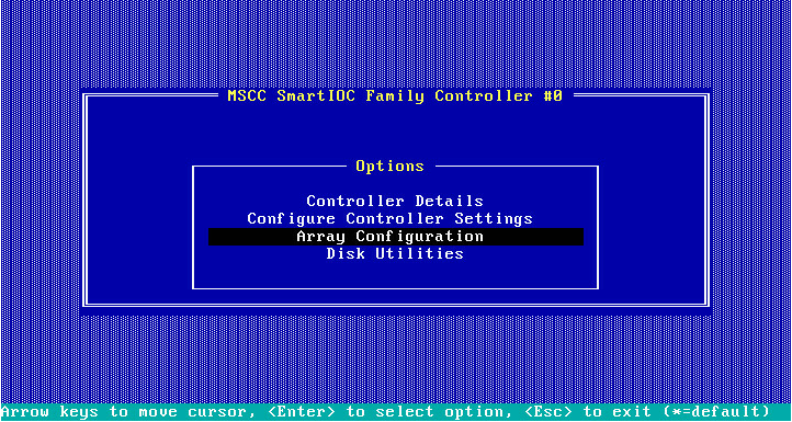
1. On the storage controller configuration screen as shown in Figure 2, select Configure Controller Settings and press Enter.
Figure 2 Storage controller configuration screen
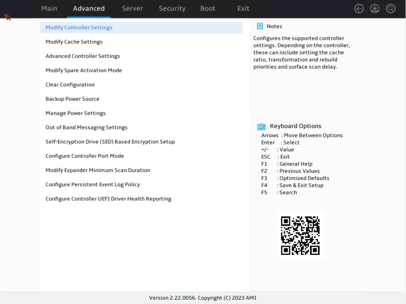
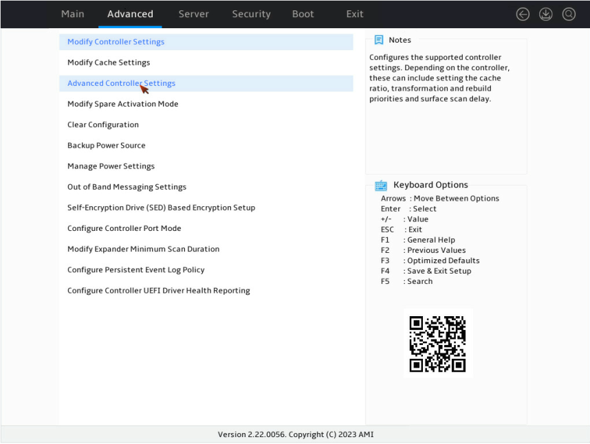
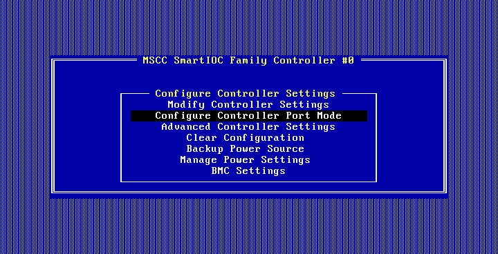
2. On the screen as shown in Figure 3, select Modify Controller Settings or Configure Controller Port Mode, and press Enter.
This section uses Modify Controller Settings as an example.
Figure 3 Configure Controller Settings screen
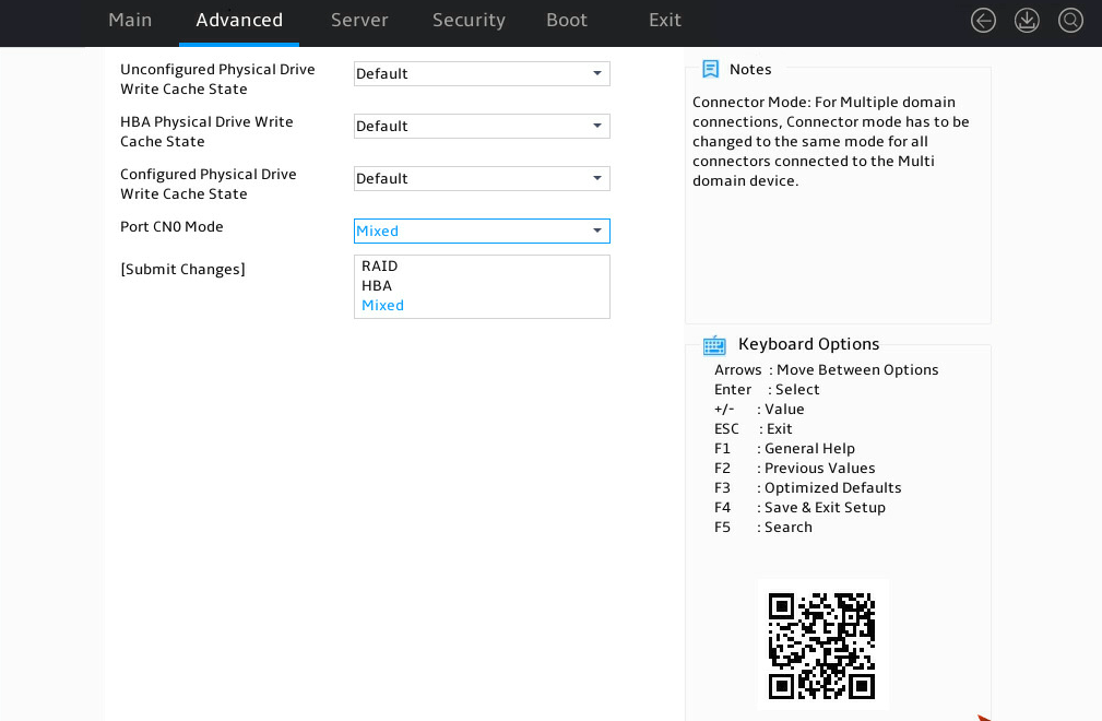
3. On the screen as shown in Figure 4, change the operating mode for Port CN0 Mode or Port CN1 Mode (as a best practice, make sure their operating modes are the same), select Submit Changes, and press Enter.
Figure 4 Modify Controller Settings screen

Figure 4 shows a screen with no RAID array configured. If a RAID array is configured, the Modify Controller Settings screen is as shown in Figure 5.
Figure 5 Modify Controller Settings screen
Configuring RAID 0
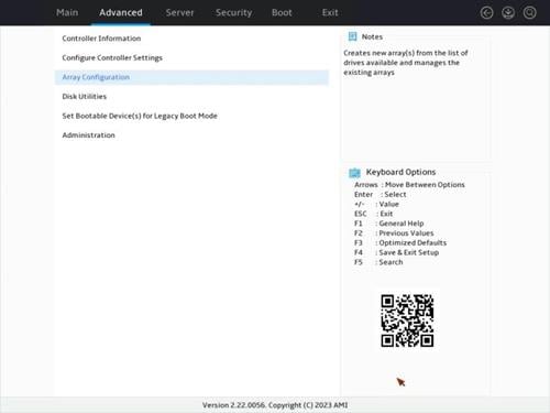
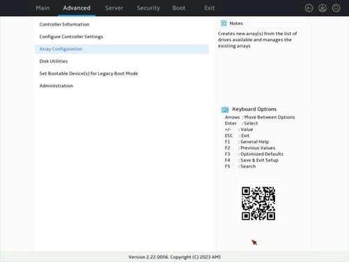
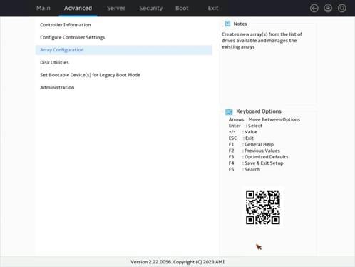
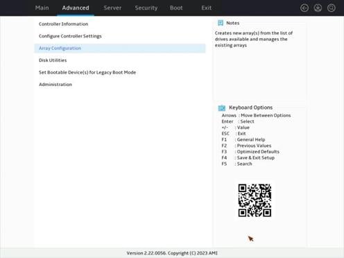
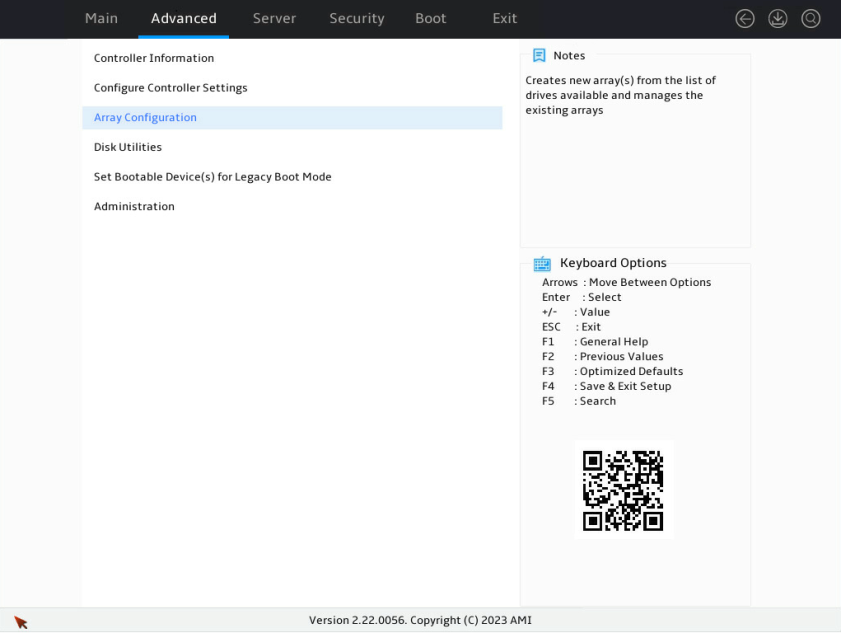
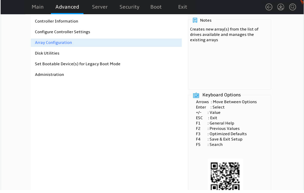
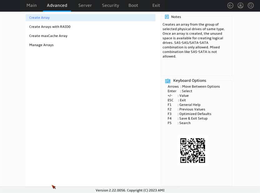
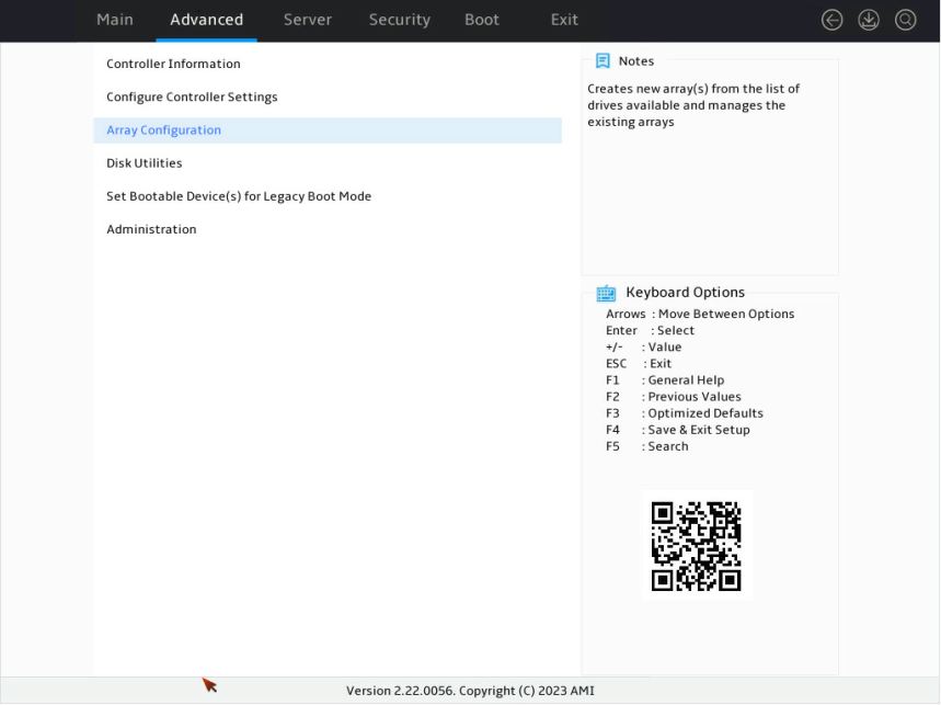
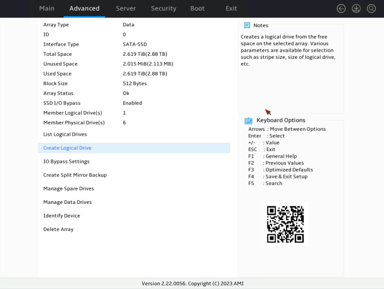
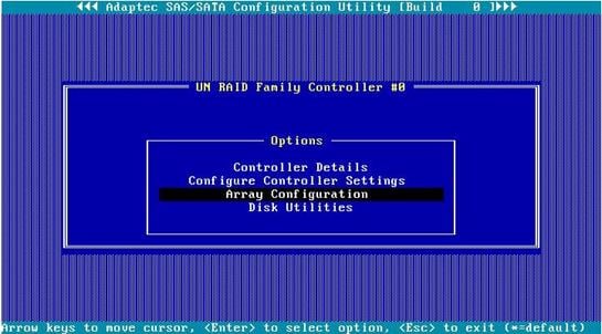
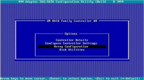
1. On the storage controller configuration screen as shown in Figure 6, select Array Configuration and press Enter.
Figure 6 Storage controller configuration screen

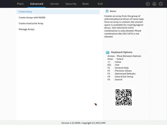
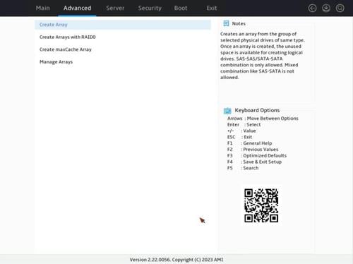
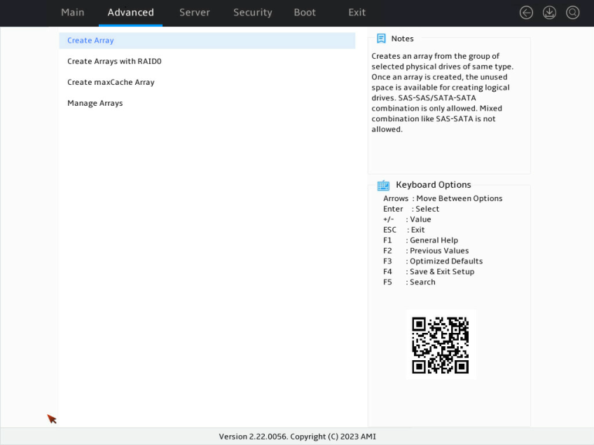
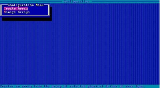
2. On the screen as shown in Figure 7, select Create Virtual Drive and press Enter.
Figure 7 Array Configuration screen

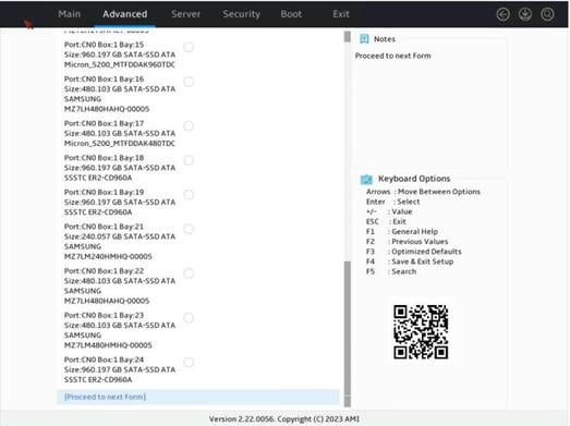
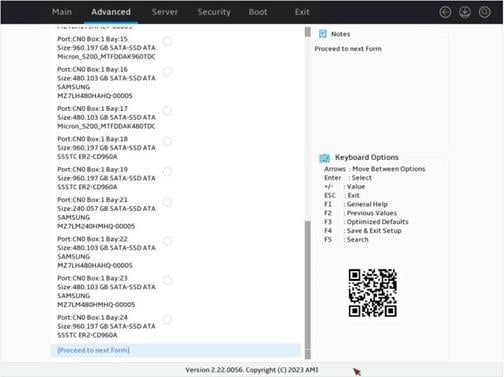
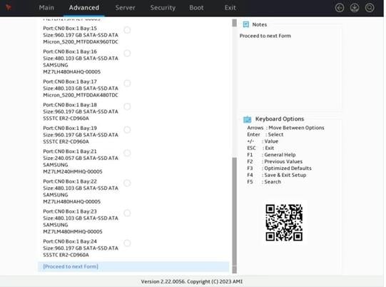
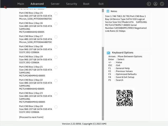
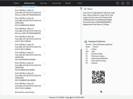
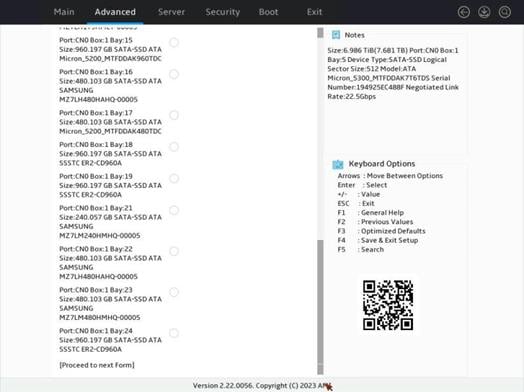
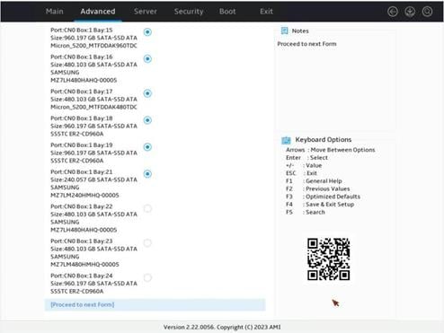
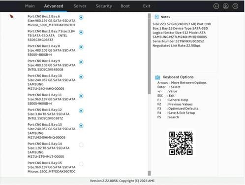
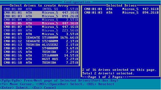
3. On the screen as shown in Figure 8, select drives of the same type. Then, select Proceed to next Form as shown in Figure 9.
Figure 8 Selecting the target drives
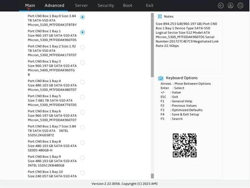
Figure 9 Proceeding to the next form
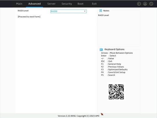
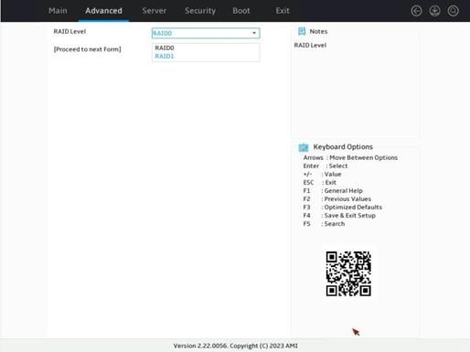
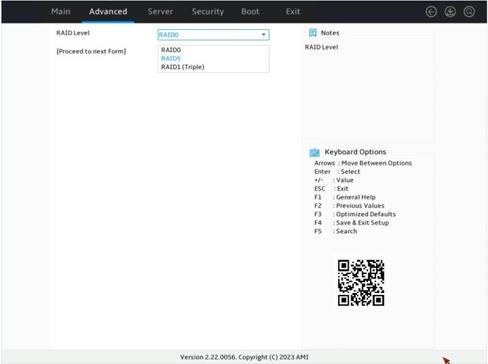
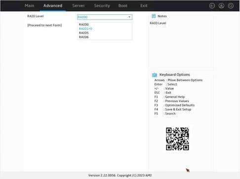
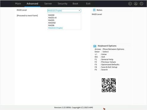
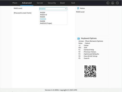
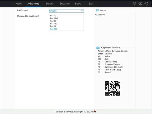
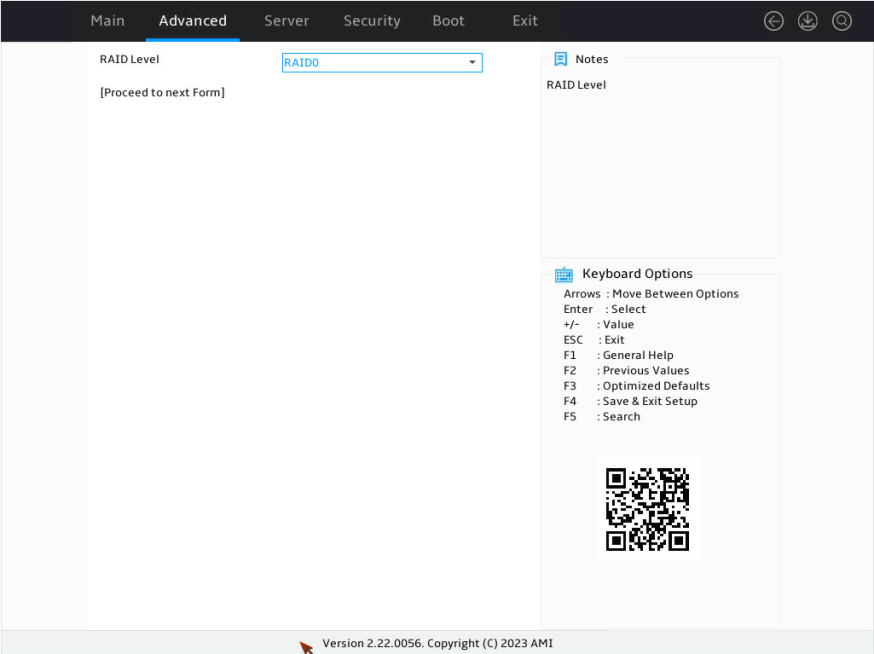
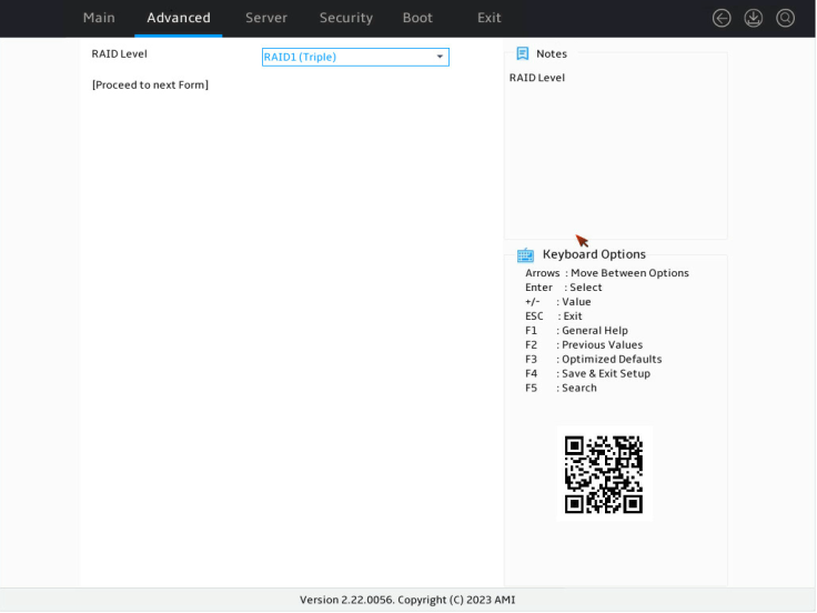
4. On the screen as shown in Figure 10, select the RAID level, press Enter, and select Proceed to next Form.
Figure 10 Setting the RAID level
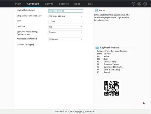
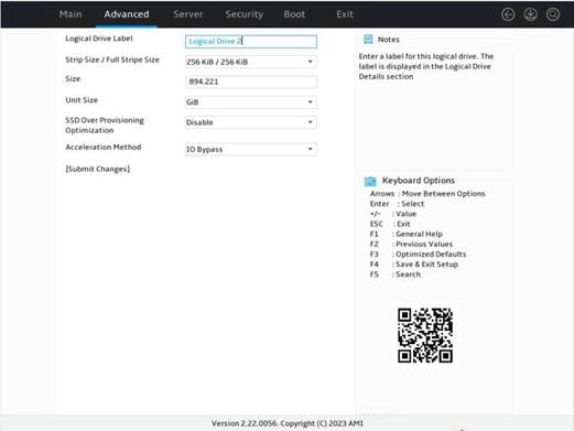
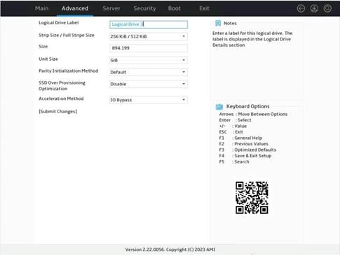
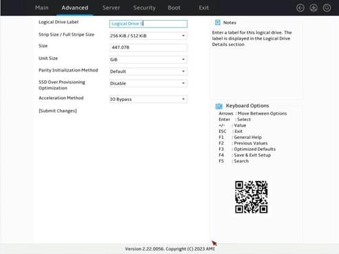
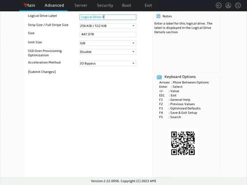
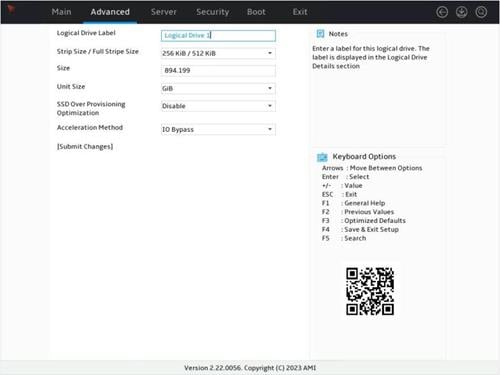
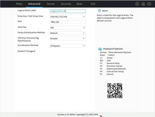
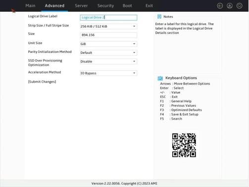
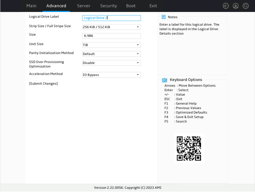
5. On the screen as shown in Figure 11, configure the parameters, press Enter, and then select Submit Changes. For more information about the parameter description, see Table 2.
Figure 11 Configuring RAID array parameters
|
Parameter |
Description |
|
Logical Drive Label |
RAID array name. |
|
Stripe Size |
Data block size for each drive. |
|
Size |
Capacity for the logical drive. |
|
Unit Size |
Size for the unit. |
|
Acceleration Method |
Logical drive acceleration method. |
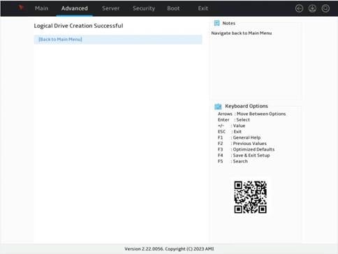
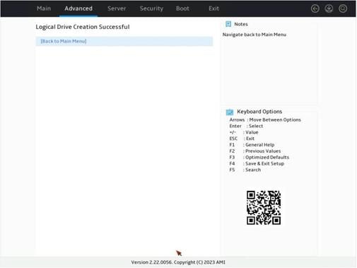
6. On the screen as shown in Figure 12, select Back to Main Menu.
Figure 12 Logical drive creation succeeded
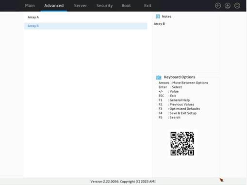
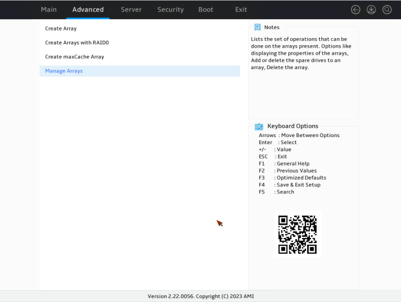
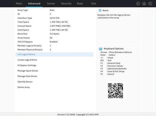
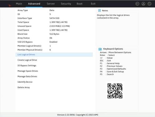
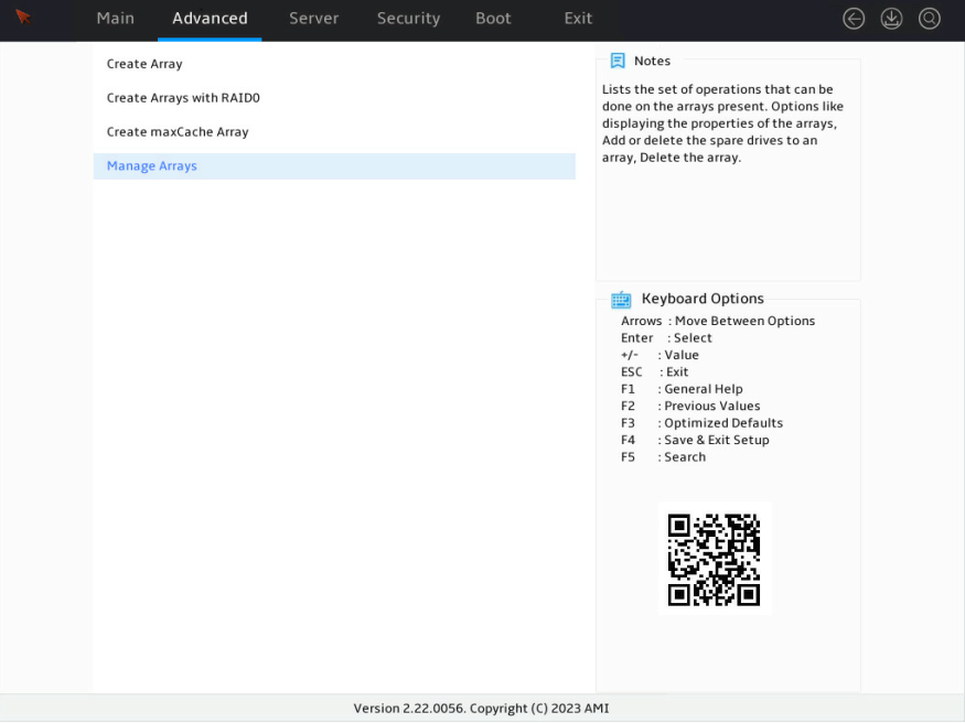
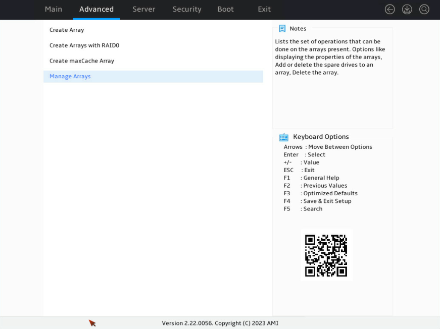
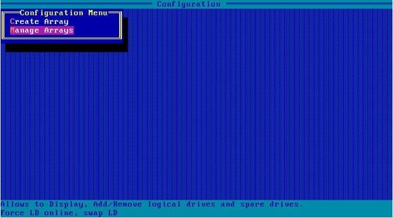
7. On the screen as shown in Figure 13, select Manage Arrays, and press Enter.
Figure 13 Storage controller configuration

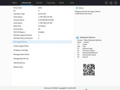
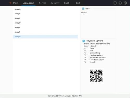
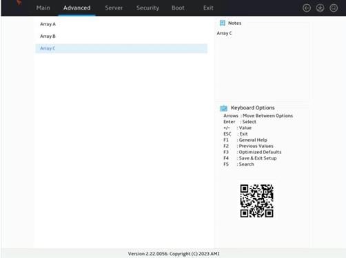
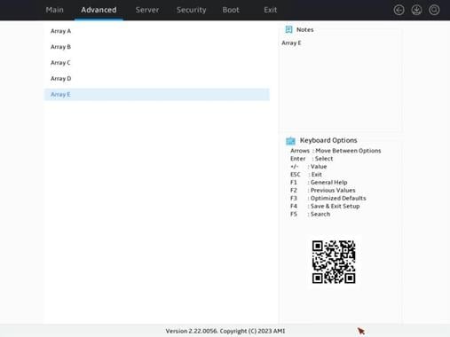
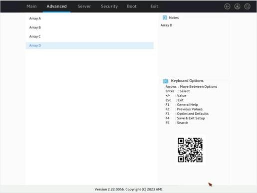
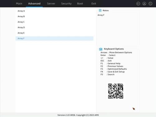
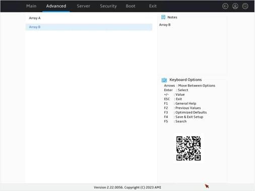
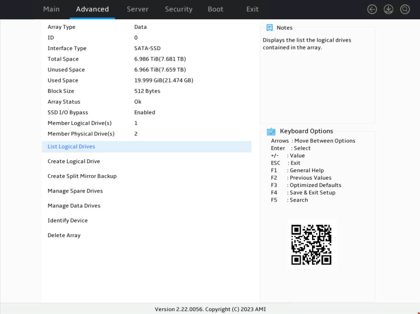
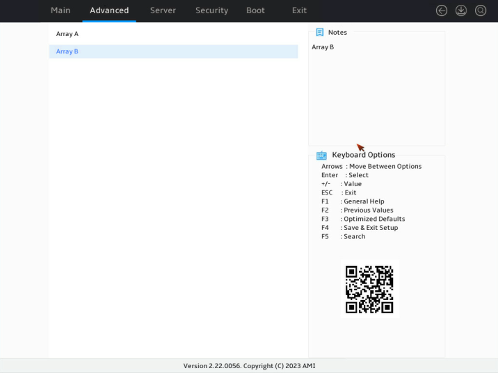
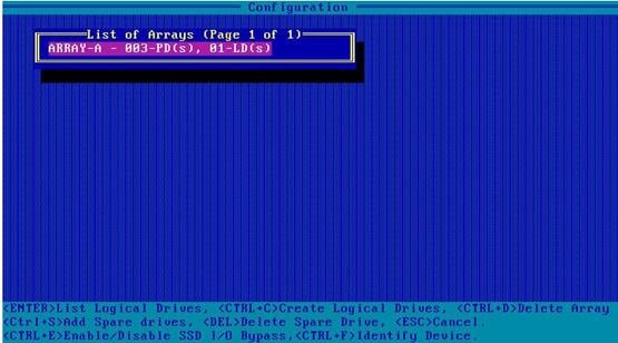
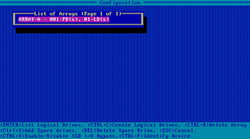
8. On the screen as shown in Figure 14, view the created arrays. Select the array where the RAID 0 logical drive resides, and then press Enter.
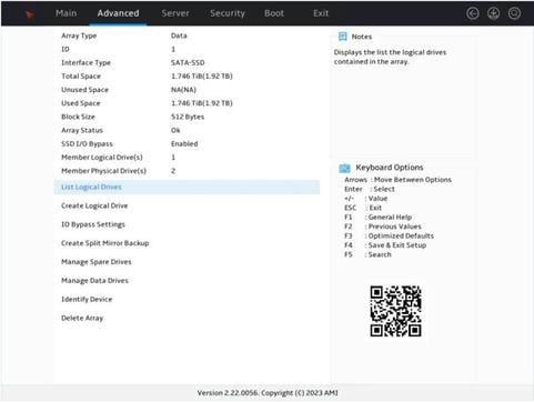
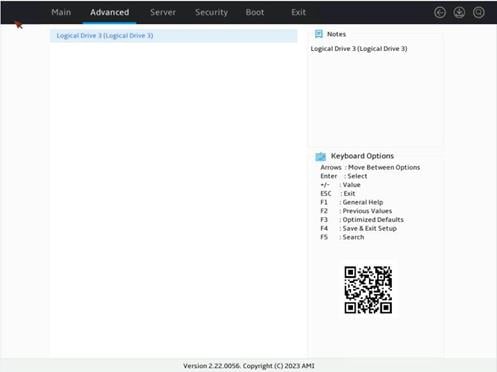
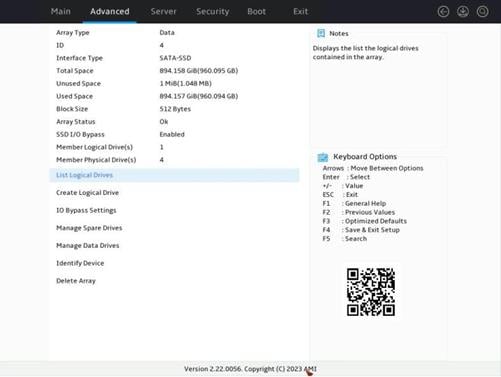
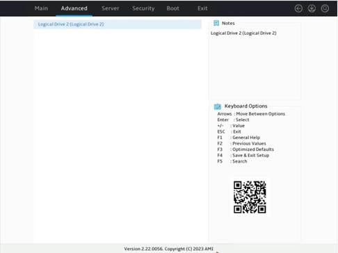
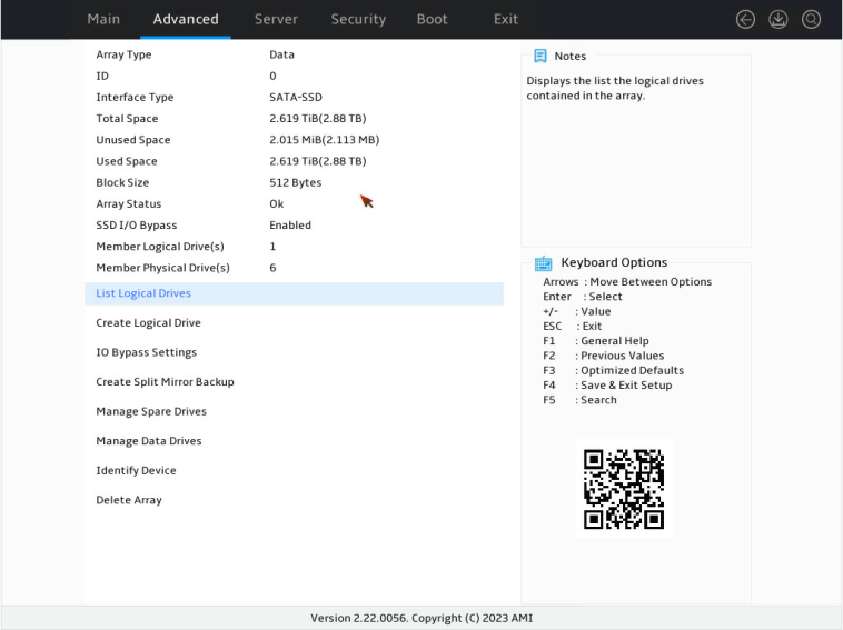
9. On the screen as shown in Figure 15, select List Logical Drives and press Enter to view detailed information about the RAID array.
Figure 15 Selecting List Logical Drives
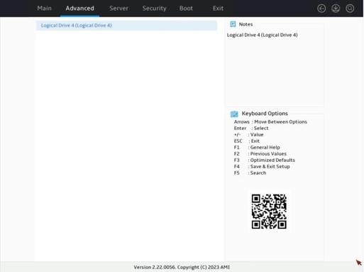
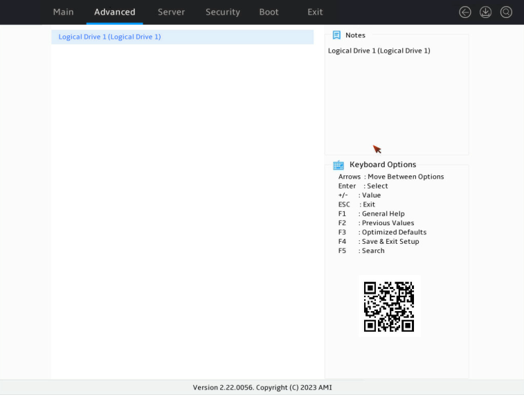
10. Selecting the target logical drive, and then press Enter.
Figure 16 Selecting Logical Drive 1

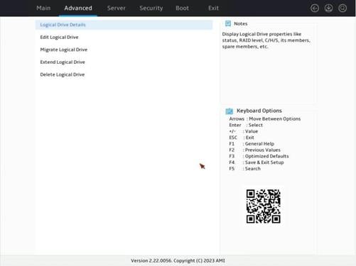
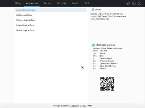
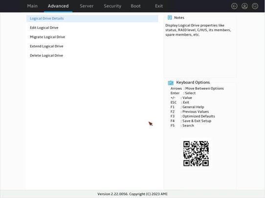
11. Selecting Logical Drive Details and then press Enter to view the logical drive details (including drive name, level, and member drive information).
Figure 17 Selecting Logical Drive Details

Configuring RAID 1
1. On the storage controller configuration screen as shown in Figure 18, select Array Configuration and then press Enter.
Figure 18 Storage controller configuration screen
2. Select Create Virtual Drive and then press Enter.
Figure 19 Selecting Create Array
3. On the screen as shown in Figure 20, select drives of the same type. Then, select Proceed to next Form as shown in Figure 21.
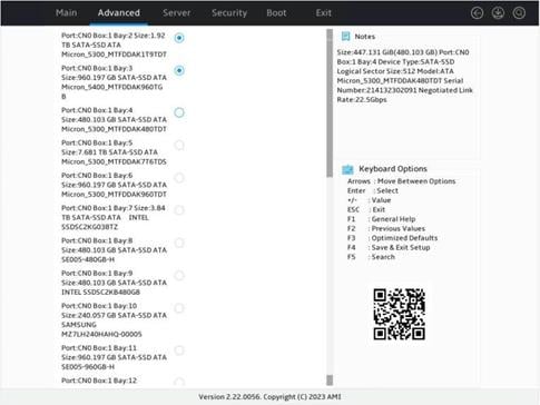
Figure 21 Selecting Proceed to next Form
4. Select the RAID level, press Enter, and then select Proceed to next Form.
Figure 22 Selecting the RAID level
5. Configure the parameters, press Enter, and then select Submit Changes. For more information about the parameter description, see Table 2.
Figure 23 Configuring RAID parameters
6. Select Back to Main Menu.
Figure 24 Logical drive creation succeeded

7. Select Manage Arrays and then press Enter.
Figure 25 Storage controller configuration screen

8. View the created arrays. Select the array where the RAID 1 logical drive resides, and press Enter.
9. Select List Logical Drives and then press Enter to view logical drives in the array.
Figure 27 Selecting List Logical Drives
10. Select the target drive, and then press Enter.
Figure 28 Selecting Logical Drive 2

11. Selecting Logical Drive Details and press Enter to view the detailed information about the logical drive (including logical drive name, level, and member drives).
Figure 29 Selecting Logical Drive Details

Configuring RAID 1 AMD
1. On the storage controller configuration screen as shown in Figure 30, select Array Configuration and then press Enter.
Figure 30 Storage controller configuration screen
2. Select Create Virtual Drive and press Enter.
Figure 31 Selecting Create Array
3. Select drives of the same type, and select Proceed to next Form.
4. Select the RAID level, press Enter, and then select Proceed to next Form.
Figure 33 Selecting the RAID1 ADM level
5. Configure the parameters, press Enter, and then select Submit Changes. For more information about the parameter description, see Table 2.
Figure 34 Configuring RAID parameters
6. Select Back to Main Menu.
Figure 35 Logical drive creation succeeded

7. Select Manage Arrays and then press Enter.
Figure 36 Storage controller configuration screen
8. View the created RAID arrays. Select the array where the RAID1 ADM logical drive resides, and then press Enter.
9. Select List Logical Drives, and press Enter to view logical drives in the array.
Figure 38 Selecting List Logical Drives

10. Select the target RAID and then press Enter.
Figure 39 Selecting Logical Drive 7

11. Select Logical Drive Details and press Enter to view detailed information about the logical drive (including the logical drive name, level, and member drives).
Figure 40 Selecting Logical Drive Details
Configuring RAID 5
1. On the storage controller configuration screen as shown in Figure 41, select Array Configuration and then press Enter.
Figure 41 Storage controller configuration screen

2. Select Create Virtual Drive and then press Enter.
Figure 42 Selecting Create Array

3. As shown in Figure 43, select drives of the same type. Then, select Proceed to next Form as shown in Figure 44.
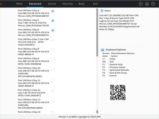
Figure 44 Selecting Proceed to next Form
4. Select the RAID level, press Enter, and then select Proceed to next Form.
Figure 45 Selecting the RAID5 level
5. Configure parameters, press Enter, and then select Submit Changes. For more information about the parameter description, see Table 2.
Figure 46 Configuring RAID parameters
6. Select Back to Main Menu.
Figure 47 Logical drive creation succeeded

7. Select Manage Arrays and then press Enter.
Figure 48 Storage controller configuration screen

8. View the created RAID arrays, select the array where the RAID5 logical drive resides, and then press Enter.
9. Select List Logical Drives and press Enter to view logical drives in the array.
Figure 50 Selecting List Logical Drives
10. Select the target logical drive, and then press Enter.
Figure 51 Selecting Logical Drive 3
11. Select Logical Drive Details and press Enter to view detailed information about the logical drive (including the logical drive name, level, and member drives).
Figure 52 Selecting Logical Drive Details

Configuring RAID 6
1. On the storage controller configuration screen as shown in Figure 53, select Array Configuration and press Enter.
Figure 53 Storage controller configuration screen
2. Select Create Virtual Drive and press Enter.
Figure 54 Selecting Create Array

3. As shown in Figure 55, select drives of the same type. Then, select Proceed to next Form as shown in Figure 56.
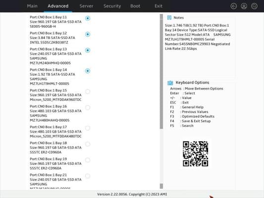
Figure 56 Selecting Proceed to next Form
4. Select the RAID level, press Enter, and then select Proceed to next Form.
Figure 57 Selecting the RAID0 level

5. Configure parameters, press Enter, and then select Submit Changes. For more information about the parameter description, see Table 2.
Figure 58 Configuring RAID parameters
6. Select Back to Main Menu.
Figure 59 Logical drive creation succeeded

7. Select Manage Arrays and then press Enter.
Figure 60 Storage controller configuration screen

8. View the created RAID arrays, select the array where the RAID 6 logical drive resides, and then press Enter.
9. Select List Logical Drives and then press Enter to view logical drives in the array.
Figure 62 Selecting List Logical Drives
10. Select the target logical drive and then press Enter.
Figure 63 Selecting Logical Drive 5

11. Select Logical Drive Details and then press Enter to view detailed information about the logical drive (including the logical drive name, level, and member drives).
Figure 64 Selecting Logical Drive Details
Configuring RAID 10
1. On the storage controller configuration screen as shown in Figure 65, select Array Configuration and then press Enter.
Figure 65 Storage controller configuration screen
2. Select Create Virtual Drive and then press Enter.
Figure 66 Selecting Create Array
3. As shown in Figure 67, select drives of the same type. Creating a RAID 10 requires a minimum of four drives. Then, select Proceed to next Form as shown in Figure 68.
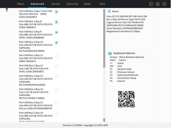
Figure 68 Selecting Proceed to next Form
4. Select the RAID level, press Enter, and then select Proceed to next Form.
Figure 69 Selecting the RAID10 level
5. Configure the parameters, press Enter, and then select Submit Changes. For more information about the parameter description, see Table 2.
Figure 70 Configuring RAID parameters
6. Select Back to Main Menu.
Figure 71 Logical drive creation succeeded

7. Select Manage Arrays and press Enter.
Figure 72 Storage controller configuration screen

8. View the created RAID arrays, select the array where the RAID 10 logical drive resides, and then press Enter.
9. Select List Logical Drives and press Enter to view logical drives in the array.
Figure 74 Selecting List Logical Drives

10. Select the target logical drive and then press Enter.
Figure 75 Selecting Logical Drive 4
11. Select Logical Drive Details and then press Enter to view detailed information about the logical drive (including logical drive name, level, and member drives).
Figure 76 Selecting Logical Drive Details

Configuring RAID 10 ADM
1. On the storage controller configuration screen as shown in Figure 77, select Array Configuration, and then press Enter.
Figure 77 Storage controller configuration screen

2. Select Create Virtual Drive and then press Enter.
Figure 78 Selecting Create Array

3. As shown in Figure 79, select drives of the same type. Creating a RAID10 ADM logical drive requires a minimum of six drives. As shown in Figure 80, select Proceed to next Form.
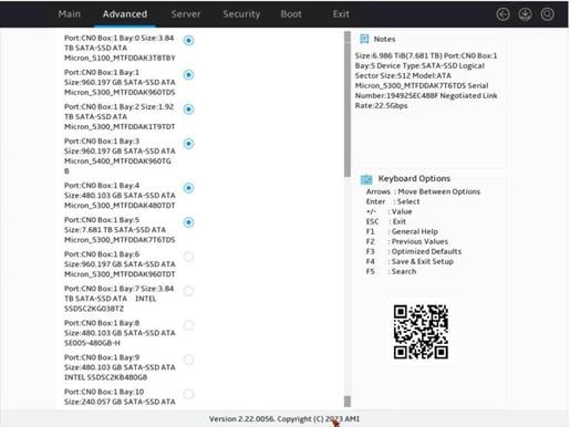
Figure 80 Selecting Proceed to next Form
4. Select the RAID level, press Enter, and then select Proceed to next Form.
Figure 81 Selecting the RAID10 level
5. Configure the parameters, press Enter, and then select Submit Changes. For more information about the parameter description, see Table 2.
Figure 82 Configuring RAID parameters
6. Select Back to Main Menu.
Figure 83 Logical drive creation succeeded

7. Select Manage Arrays and then press Enter.
Figure 84 Storage controller configuration screen

8. View the created RAID arrays, select the array where the RAID10 ADM logical drive resides, and then press Enter.
9. Select List Logical Drives and then press Enter to view logical drives in the array.
Figure 86 Selecting List Logical Drives

10. Select the target logical drive and then press Enter.
Figure 87 Selecting Logical Drive 1

11. Select Logical Drive Details and then press Enter to view detailed information about the logical drive (including logical drive name, level, and member drives).
Figure 88 Selecting Logical Drive Details
Configuring RAID 50
1. On the storage controller configuration screen as shown in Figure 89, select Array Configuration, and then press Enter.
Figure 89 Storage controller configuration screen
2. Select Create Virtual Drive and then press Enter.
Figure 90 Selecting Create Array

3. Select drives of the same type, and then select Proceed to next Form.
4. Select the RAID level, press Enter, and then select Proceed to next Form.
Figure 92 Selecting the RAID10 level
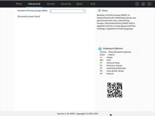
5. Select Proceed to next Form.
Figure 93 Selecting the number of parity groups
6. Configure the parameters, press Enter, and then select Submit Changes. For more information about the parameter description, see Table 2.
Figure 94 Configuring RAID parameters
7. Select Back to Main Menu.
Figure 95 Logical drive creation succeeded
8. Select Manage Arrays and then press Enter.
Figure 96 Storage controller configuration screen

9. View the created RAID arrays, select the array where the RAID50 logical drive resides, and then press Enter.
10. Select List Logical Drives and then press Enter to view logical drives in the array.
Figure 98 Selecting List Logical Drives
11. Select the target logical drive and then press Enter.
Figure 99 Selecting Logical Drive 6

12. Select Logical Drive Details and then press Enter to view detailed information about the logical drive (including logical drive name, level, and member drives).
Figure 100 Selecting Logical Drive Details

Configuring RAID 60
1. On the storage controller configuration screen as shown in Figure 101, select Array Configuration, and then press Enter.
Figure 101 Storage controller configuration screen
2. Select Create Virtual Drive and then press Enter.
Figure 102 Selecting Create Array

3. Select drives of the same type, and then select Proceed to next Form.
4. Select the RAID level, press Enter, and then select Proceed to next Form.
Figure 104 Selecting the RAID60 level
5. Select Proceed to next Form.
Figure 105 Selecting the number of parity groups
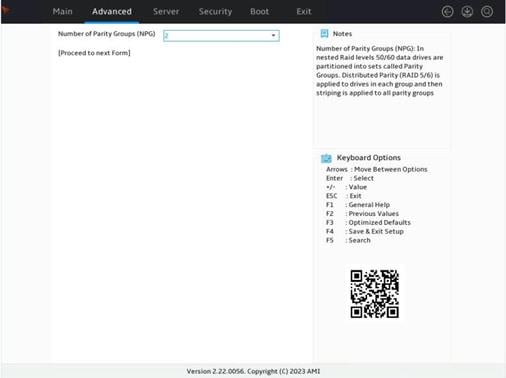
6. Configure the parameters, press Enter, and then select Submit Changes. For more information about the parameter description, see Table 2.
Figure 106 Configuring RAID parameters
7. Select Back to Main Menu.
Figure 107 Logical drive creation succeeded

8. Select Manage Arrays and then press Enter.
Figure 108 Storage controller configuration screen

9. View the created RAID arrays, select the array where the RAID60 logical drive resides, and then press Enter.
10. Select List Logical Drives and then press Enter to view logical drives in the array.
Figure 110 Selecting List Logical Drives

11. Select the target logical drive and then press Enter.
Figure 111 Selecting Logical Drive 2
12. Select Logical Drive Details and then press Enter to view detailed information about the logical drive (including logical drive name, level, and member drives).
Figure 112 Selecting Logical Drive Details

Viewing controller properties
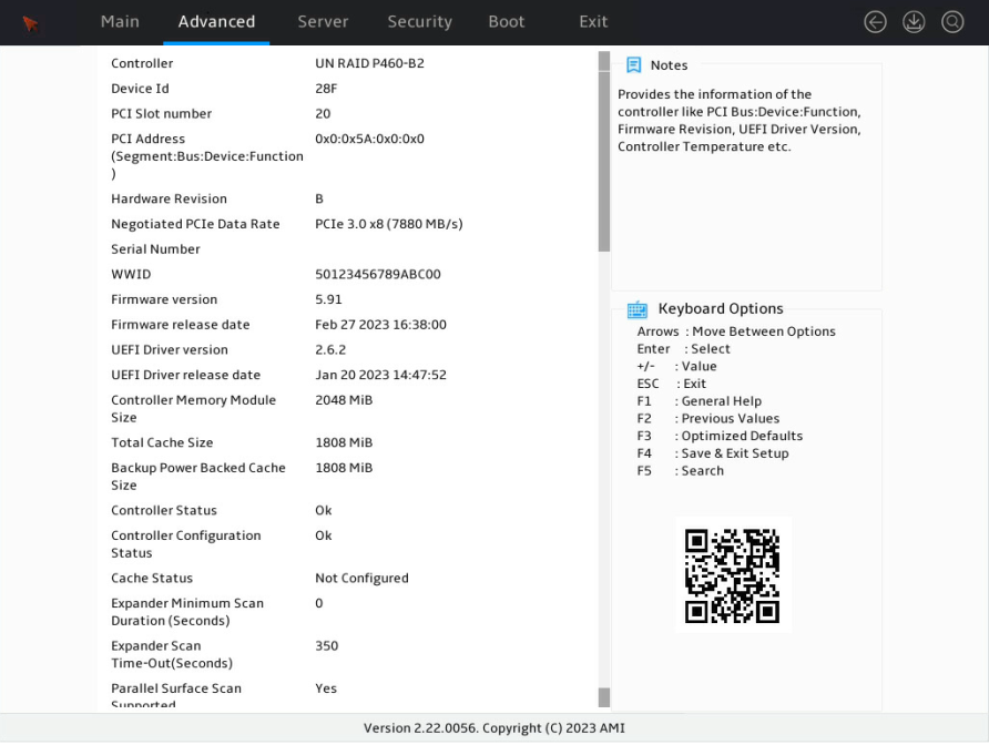
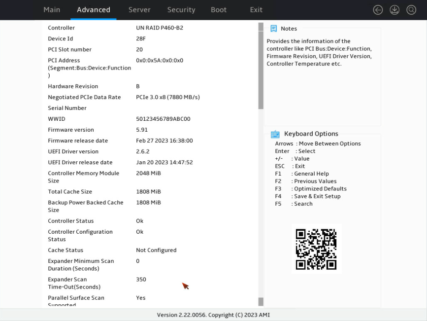
1. On the storage controller configuration screen as shown in Figure 113, select Controller Information and press Enter.
Figure 113 Storage controller configuration screen
2. On the screen as shown in Figure 114, you can see basic information for the storage controller. For more information about the parameter description, see Table 3.
Figure 114 Controller Information screen
|
Parameter |
Description |
|
Controller |
Storage controller model. |
|
PCI Slot number |
PCIe bus address assigned to the storage controller by the BIOS. |
|
PCI Address |
PCI address of the storage controller. |
|
Hardware Revision |
Hardware version. |
|
Serial Number |
Serial number of the storage controller. |
|
WWID |
Unique identifier of the storage controller. |
|
Controller Memory Module Size |
Cache size of the storage controller. |
|
Controller Status |
Status of the storage controller. |
|
Controller Mode |
Current mode of the storage controller, including: · RAID—In this mode, logical drives attached to a storage controller will report to the OS, but passthrough drives will not. That is, a drive is available in the OS only when the drive is added to a RAID array. · HBA—In this mode, all RAID functions of a storage controller are disabled. All drives attached to the storage controller are considered as passthrough drives. That is, all drives can operate in passthrough mode. · Mixed—In this mode, both logical drives attached to a storage controller and passthrough drives will report to the OS. That is, the drives can operate in both RAID mode and passthrough mode. By default, the controller mode is Mixed. |
|
Supported Modes |
Supported modes of ports on the storage controller, including: · Port CN0:RAID HBA Mixed · Port CN1:RAID HBA Mixed |
Configuring hot spare drives
1. On the storage controller configuration screen as shown in Figure 115, select Array Configuration and press Enter.
Figure 115 Storage controller configuration screen
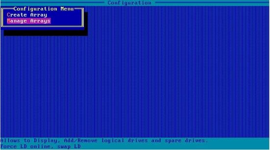
2. On the screen as shown in Figure 116, select Manage Arrays and press Enter.
Figure 116 Array Configuration screen
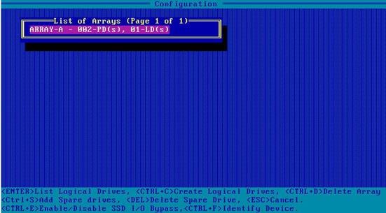
3. On the screen as shown in Figure 117, select the target array and press Enter.
Figure 117 Selecting the target array
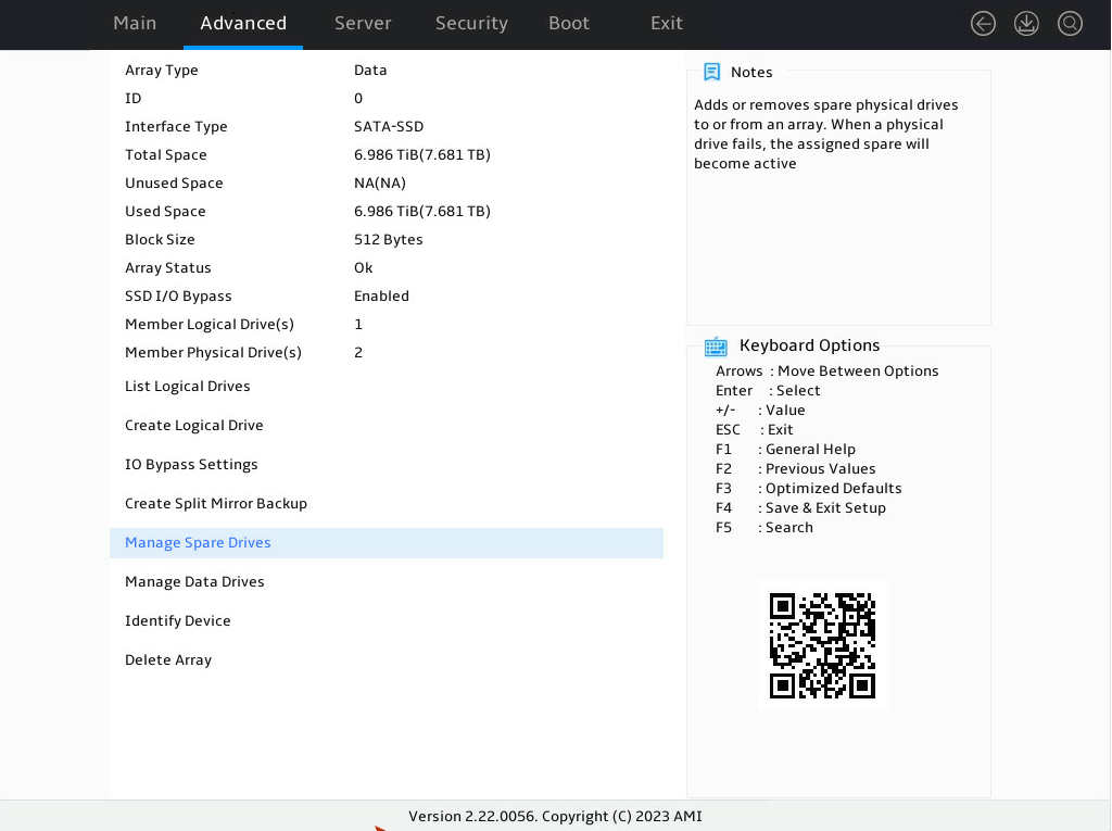
4. On the screen as shown in Figure 118, select Manage Spare Drives and press Enter.
Figure 118 Selecting Manage Spare Drivers
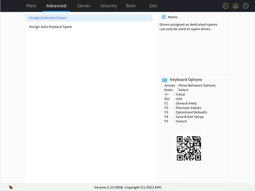
5. On the screen as shown in Figure 119, select Assign Dedicated Spare (for specifying a hot spare drive for the specified array) or Assign Auto Replace Spare (for automatically replacing failed drives) and press Enter.
Figure 119 Selecting the spare type
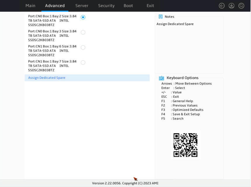
6. On the screen as shown in Figure 120, select the target drives. ([Enabled] following a drive means that the drive has been selected.) Then, select Assign Dedicated Spare and press Enter.
Figure 120 Selecting the target drives
Expanding a RAID array
1. Enter the storage controller configuration screen.
2. As shown in Figure 121, select Array Configuration, and then press Enter.
Figure 121 Storage controller configuration screen
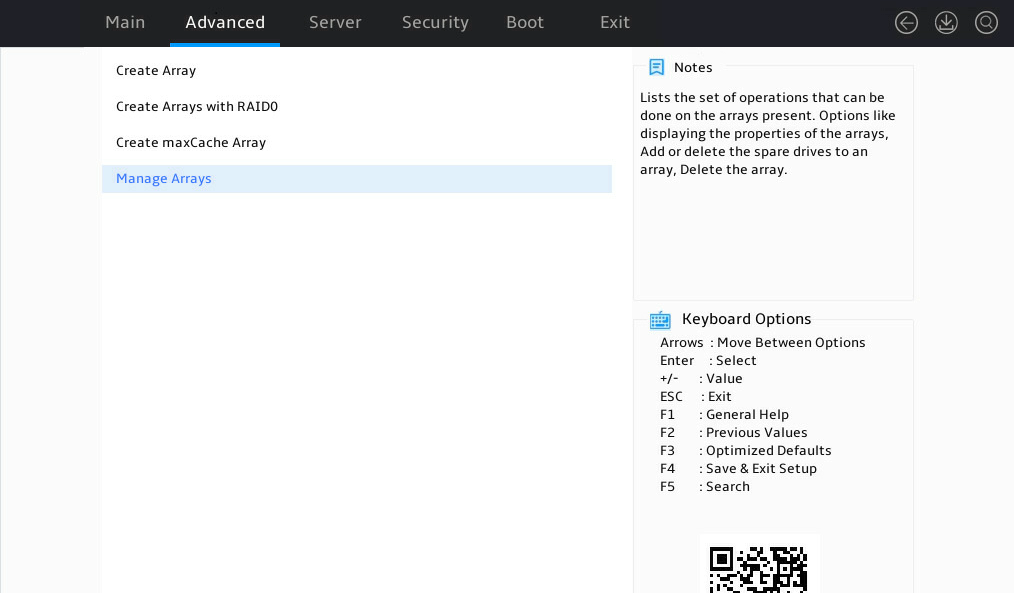
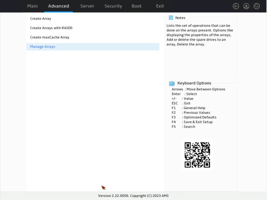
3. As shown in Figure 122, select Manage Arrays and press Enter.
Figure 122 Array Configuration screen
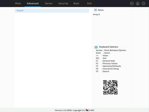
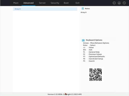
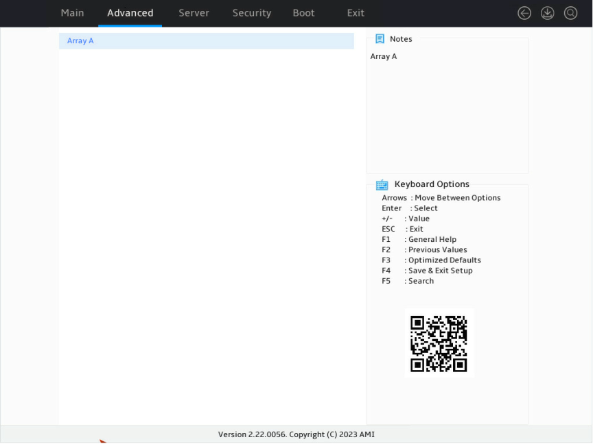
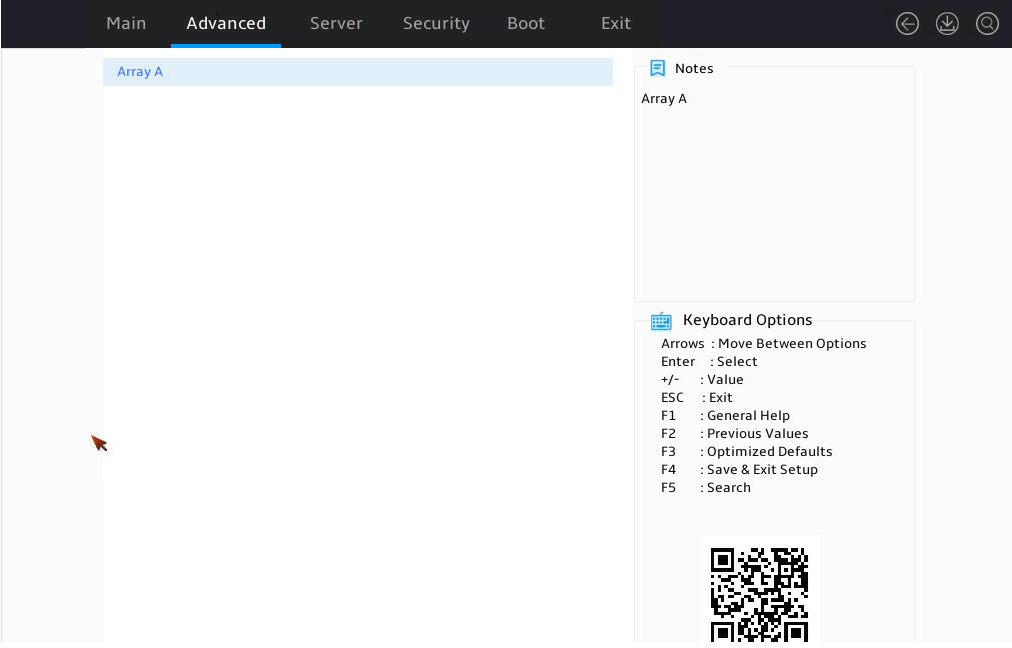
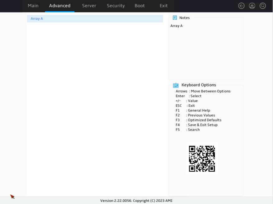
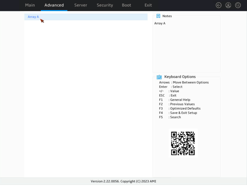
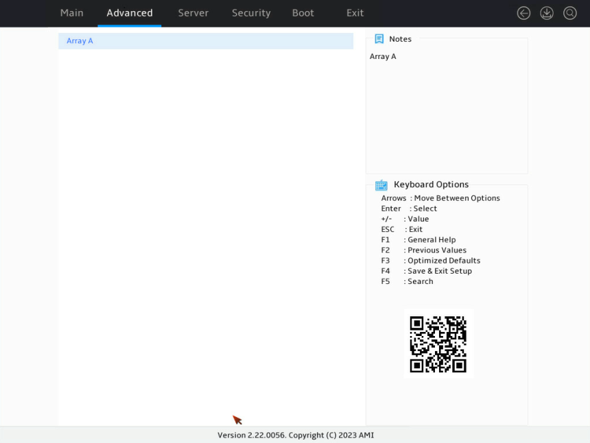
4. Select the target array, as shown in Figure 123. This example selects Array A.
Figure 123 Manage Arrays screen
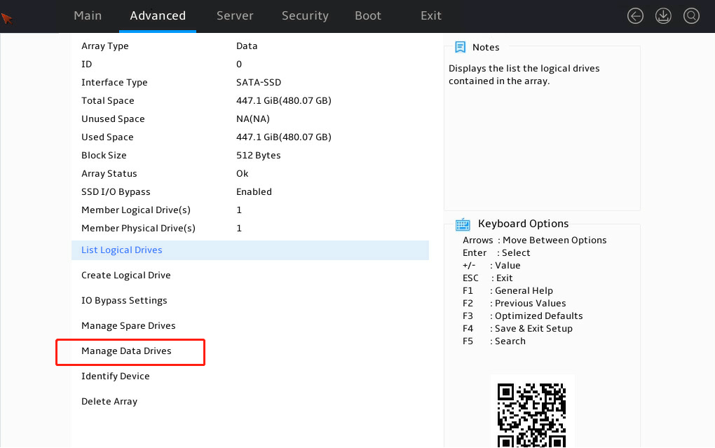
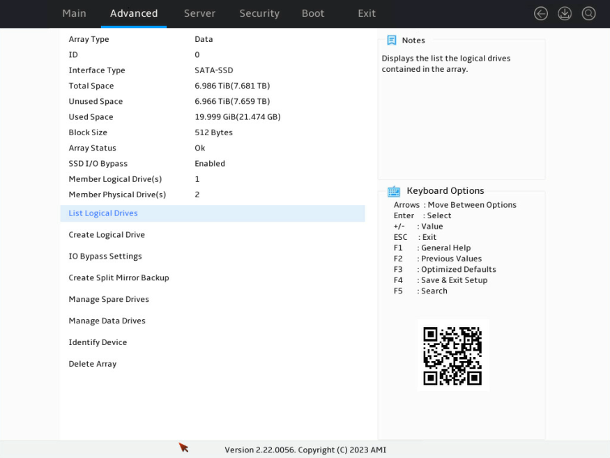
5. As shown in Figure 124, select Manage Data Drives.
Figure 124 Selecting Manage Data Drivers
6. As shown in Figure 125, select Add Drive(s).
Figure 125 Selecting Add Drive(s)
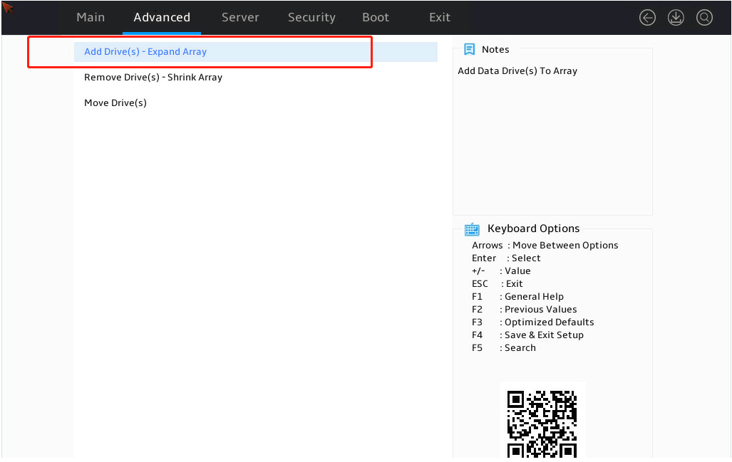
7. As shown in Figure 126, select the drive to be added and click Proceed to next Form.

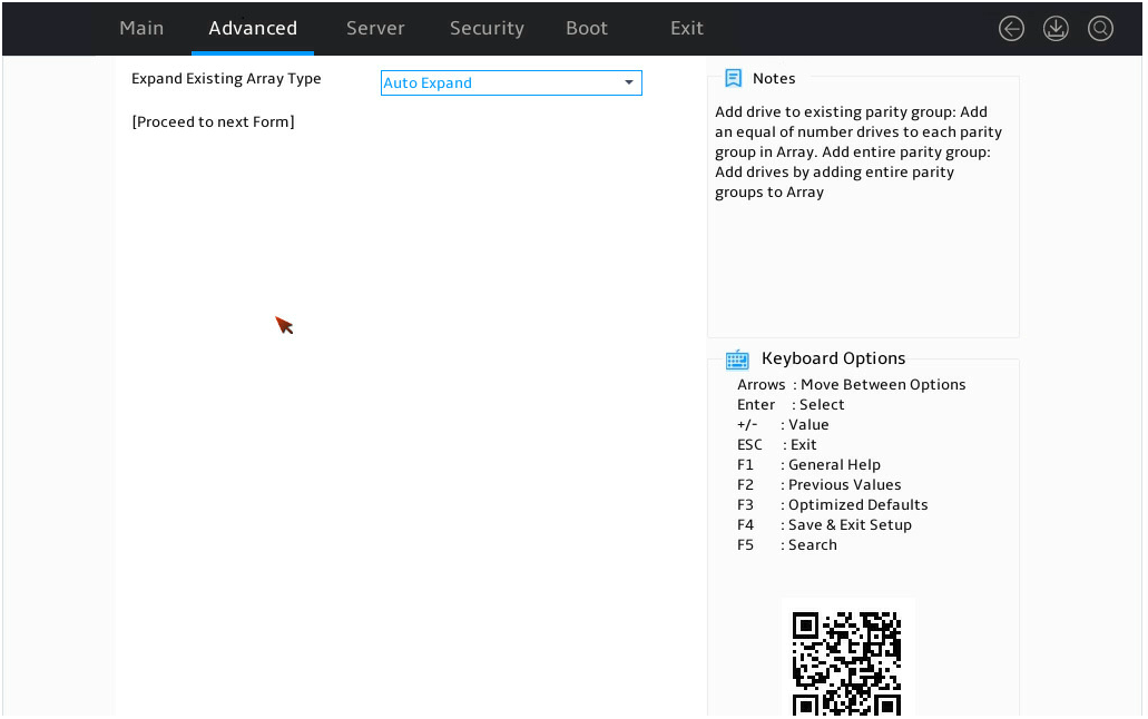
8. As shown in Figure 127, select Auto Expand and click Proceed to next Form.
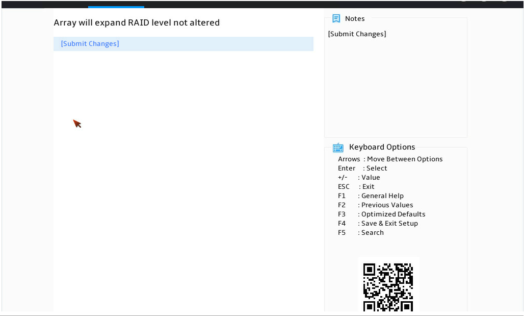
9. As shown in Figure 128, click Submit Changes.
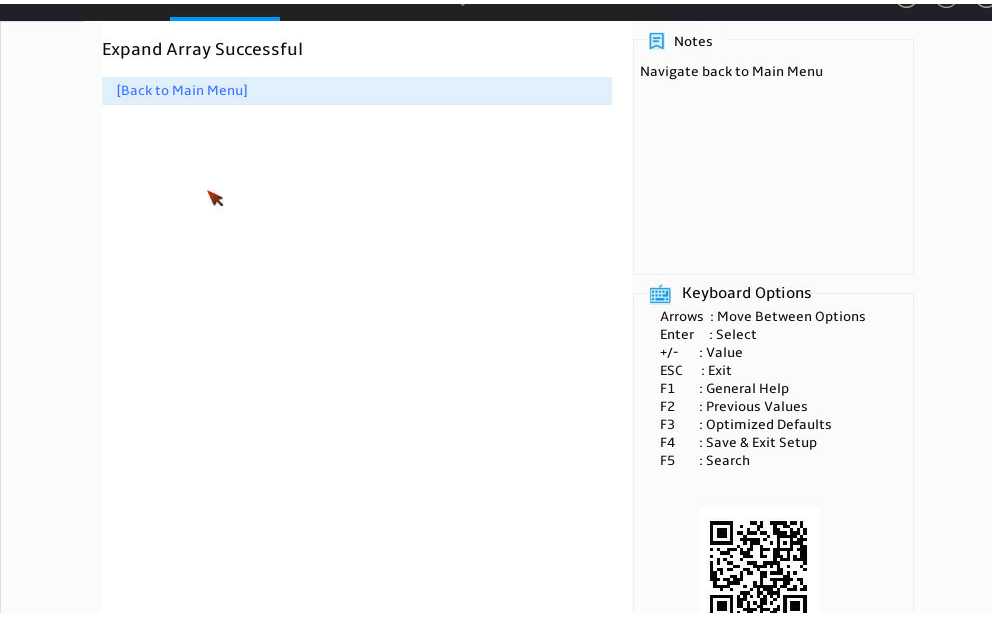
When the operation finishes, the screen is as shown in Figure 129.
Figure 129 Completing expanding a RAID array
Deleting a RAID array
This task allows you to delete a RAID array and the logical drives contained in it.
|
|
NOTE: Deleting logical drives in the middle of a RAID array might cause discontinuous sectors on the physical drives of this array. As a consequence, the operation might affect the drive read and write rate and limit the operations on logical drives performed by using RAID array configuration tools. As a best practice to avoid these problems, delete logical drives from back to front in sequence. If you delete logical drives in the middle, wait for all the logical drives to enter normal state before executing any other operations. |
To delete a RAID array:
1. Access the storage controller configuration screen.
2. On the storage controller configuration screen as shown in Figure 130, select Array Configuration and press Enter.
Figure 130 Storage controller configuration screen

3. On the screen as shown in Figure 131, select Manage Arrays and press Enter.
Figure 131 Array Configuration screen
4. On the screen as shown in Figure 132, select the target array and press Enter.
Figure 132 Selecting the target array
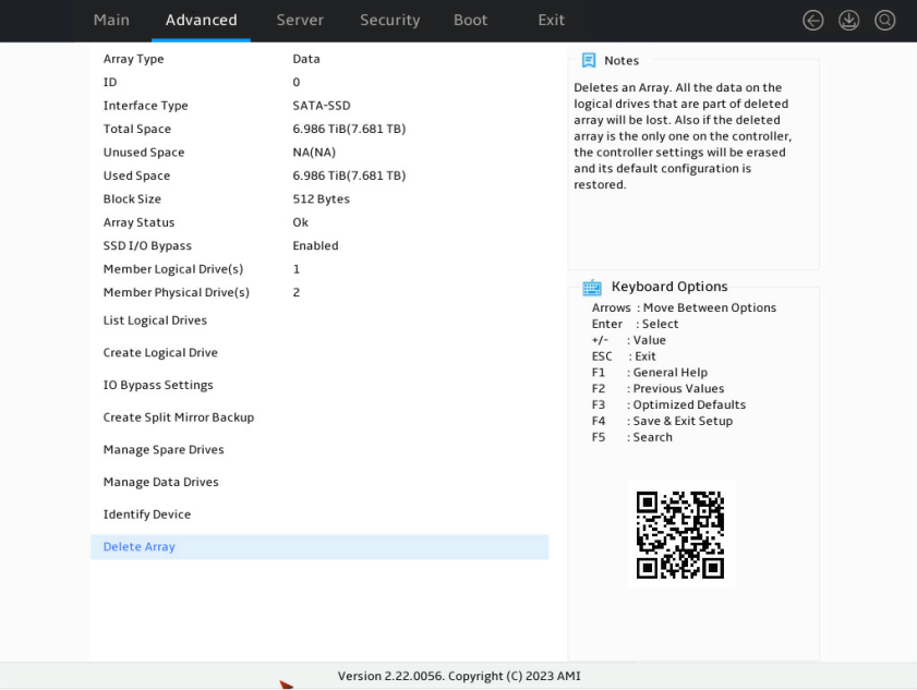
5. On the screen as shown in Figure 133, select Delete Array and press Enter.
Figure 133 Selecting Delete Array
Viewing drive information
1. Access the storage controller configuration screen.
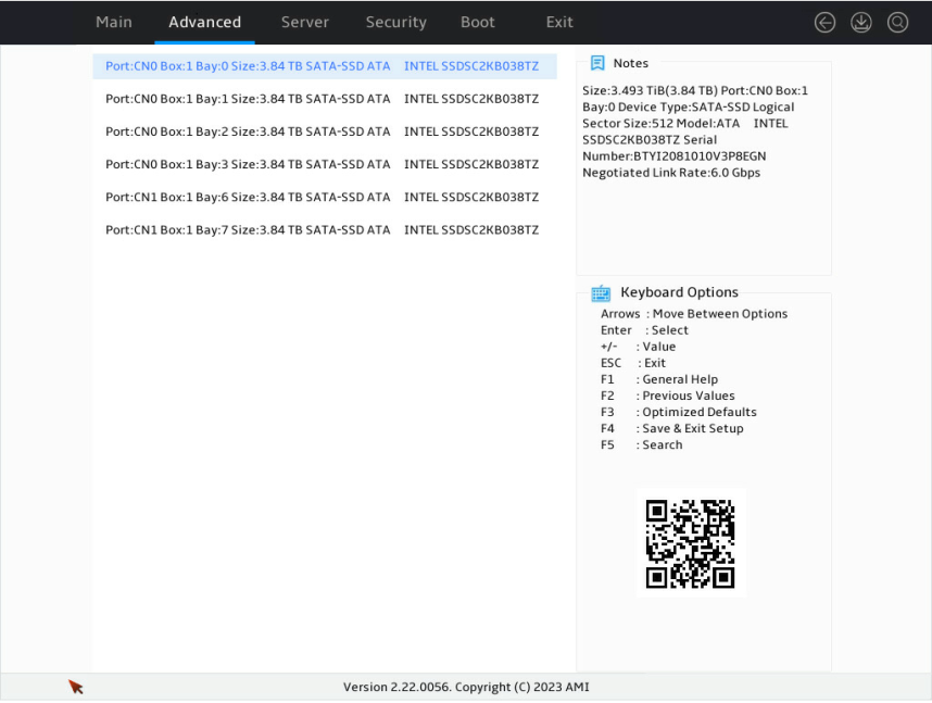
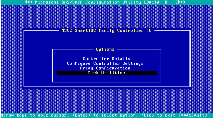
2. On the storage controller configuration screen as shown in Figure 134, select Disk Utilities and press Enter.
Figure 134 Storage controller configuration screen
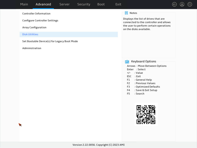
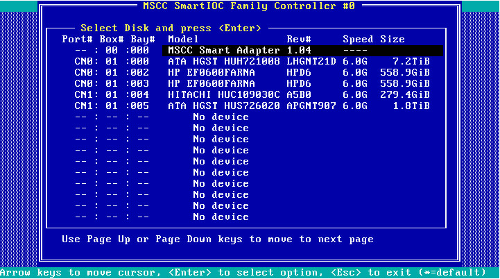
3. On the screen as shown in Figure 135, you can see information about all available drives.
Locating drives
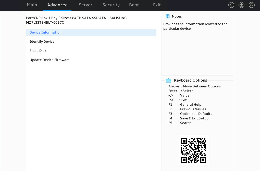
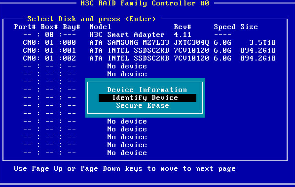
1. Select the target drive on the screen as shown in Figure 135 and press Enter.
2. On the screen as shown in Figure 136, select Identify Device and press Enter.
Figure 136 Selecting Identify Device
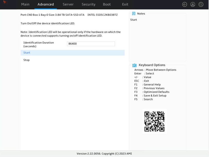
3. On the screen as shown in Figure 137, select Start, and the Fault/UID LED on the drive turns steady blue. If you select Stop, the Fault/UID LED on the drive turns off.
Figure 137 Identifying the drive
Erasing drives
Restrictions and guidelines
You can erase only physical drives.
To avoid drive failure, do not power off, restart, or remove the drive during the erasing process.
Procedure
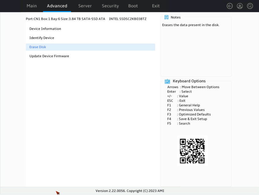
1. On the storage controller configuration screen as shown in Figure 135, select the drive to be erased, and then press Enter.
2. On the screen as shown in Figure 138, select Erase Disk and then press Enter.
3. On the screen as shown in Figure 139, select the erase pattern, and press Enter.
Figure 139 Selecting the erase pattern

Table 4 Parameter description
|
Parameter |
Description |
|
Three-passes: Random + Random + All zeroes |
Write random numbers to the drive twice, and write all zeros to the entire drive on the third pass. |
|
Two-passes: Random +All zeroes |
Write random numbers to the drive once, and write all zeros to the entire drive on the second pass. |
|
One-pass: Write All zeroes |
Write all zeros to the entire drive. |
|
Restricted Sanitize Block Erase |
Restricted drive erasure refers to the use of the Sanitize Block Erase command to perform data deletion on SSDs. This command notifies the internal controller of the SSD to execute the erase operation. This operation clears all user data, removes all unused data blocks, and resets the flash memory storage in the SSD. |
|
Unrestricted Sanitize Block Erase |
Unrestricted drive erasure. Recoverable drives will not be affected if drive erasure fails. |
|
Restricted Sanitize Crypto Scramble |
The method of data deletion on SSDs that use encryption technology to protect data security is not about completely erasing the data, but rather making the data unreadable. It requires specific user access controls or other security measures to enhance the privacy protection of the data. |
|
Unrestricted Sanitize Crypto Scramble |
Unrestricted and highly secure data deletion method involves the use of encryption and randomization techniques to obfuscate and completely erase the data on the storage device, ensuring privacy and security protection. |
4. On the screen as shown in Figure 140, select Start Erase, and press Enter.

Viewing storage controller information
1. Access the storage controller configuration screen.
2. On the storage controller configuration screen as shown in Figure 141, select Controller Information and press Enter.
Figure 141 Storage controller configuration screen
3. On the screen as shown in Figure 142, view storage controller information.
Figure 142 Viewing storage controller information
Modifying storage controller settings
1. Access the storage controller configuration screen.
2. On the storage controller configuration screen as shown in Figure 143, select Configure Controller Settings and press Enter.
Figure 143 Storage controller configuration screen
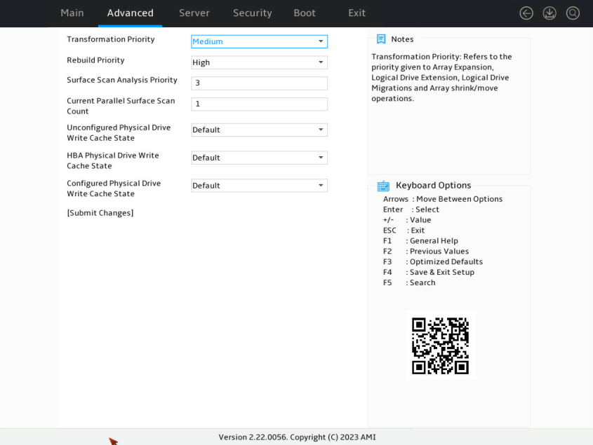
3. On the screen as shown in Figure 144, select Modify Controller Settings and press Enter.
Figure 144 Controller Settings screen
4. On the screen as shown in Figure 145, modify the basic storage controller settings as needed. If no logical drives are available, you can only modify the operating mode for the storage controller.
Figure 145 Modify Controller Settings screen
Clearing storage controller configuration information
1. Access the storage controller configuration screen.
2. On the storage controller configuration screen as shown in Figure 146, select Configure Controller Settings and press Enter.
Figure 146 Storage controller configuration screen

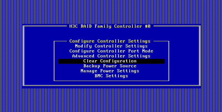
3. On the screen as shown in Figure 147 or Figure 148, select Clear Configuration and press Enter.
Figure 147 Configure Controller Settings screen (for the RAID-P460-B2)


|
|
NOTE: The RAID-P460-M2, RAID-P460-B2, RAID-P460-M4, and RAID-P460-B4 storage controllers support the Backup Power Source option. This option indicates that the controllers can provide power fail safeguard if it has a supercapacitor connected. |
4. On the screen as shown in Figure 149, select Delete All Array Configurations or Delete Configuration metadata on all physical drives and press Enter. This example selects Delete All Array Configurations.
Figure 149 Selecting Delete All Array Configurations

Table 5 Parameter description
|
Parameter |
Description |
|
Delete All Array Configurations |
Clear all created RAID and related array configuration information. |
|
Delete Configuration metadata on all physical drives |
Clear all invalid RAID information remaining in physical drives. |
5. On the screen as shown in Figure 150, select Submit Changes and press Enter.
Figure 150 Selecting Submit Changes

Setting the HBA mode
1. Access the storage controller configuration screen.
2. On the storage controller configuration screen as shown in Figure 151, select Configure Controller Settings and press Enter.
Figure 151 Storage controller configuration screen

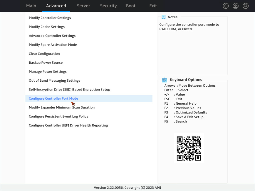
3. On the screen as shown in Figure 152, select Configure Controller Port Mode and press Enter.
Figure 152 Configure Controller Settings screen
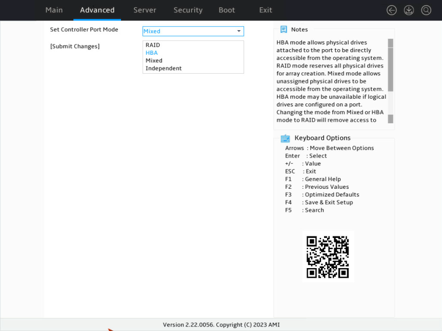
4. On the screen as shown in Figure 153, select HBA for Set Controller Port Mode and press Enter.
Figure 153 Configure Controller Port Mode screen
Creating multiple virtual drives (VDs)
1. Access the storage controller configuration screen.
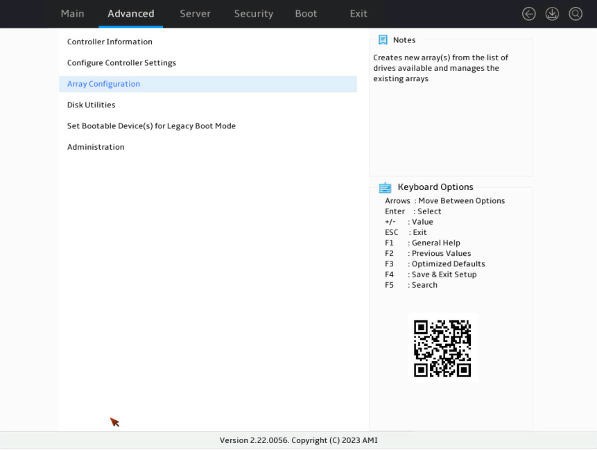
2. On the storage controller configuration screen as shown in Figure 154, select Array Configuration and press Enter.
Figure 154 Storage controller configuration screen
3. On the screen as shown in Figure 155, select Manage Arrays and press Enter.
Figure 155 Array Configuration screen
4. On the screen as shown in Figure 156, select an array to add VDs. This example selects Array A.
Figure 156 Manage Arrays screen
5. On the screen as shown in Figure 157, select Create Logical Drive.
Figure 157 Array management screen
6. On the screen as shown in Figure 158, select a RAID level, strip size, and capacity.
Figure 158 Create Logical Drive screen
Upgrading the storage controller firmware online
The BIOS supports only online firmware upgrade. To upgrade the SEEPROM, contact Technical Support.
To upgrade the storage controller firmware online:
1. Access the storage controller configuration screen.
2. On the storage controller configuration screen as shown in Figure 159, select Administration and press Enter.
Figure 159 Storage controller configuration screen
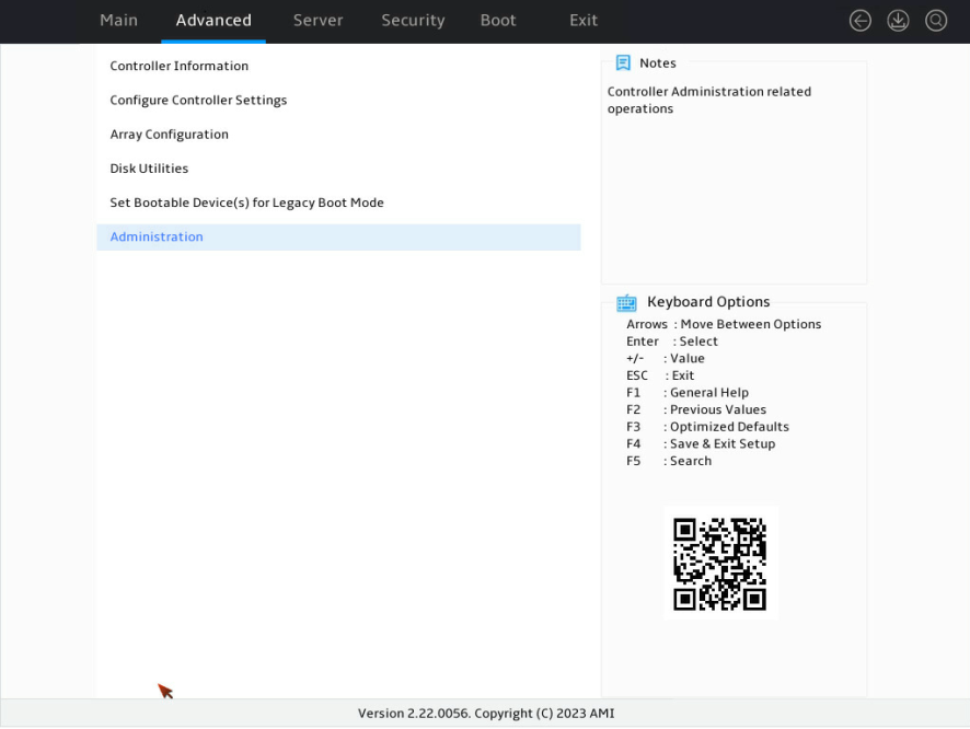
3. On the screen as shown in Figure 160, select Flash Controller Firmware and press Enter.
Figure 160 Administration screen

4. On the screen as shown in Figure 161, select Select Firmware File to flash and press Enter.
Figure 161 Selecting Select Firmware File to flash

5. On the screen as shown in Figure 162, select the target device where the update file is located and press Enter.
Figure 162 Selecting the target device

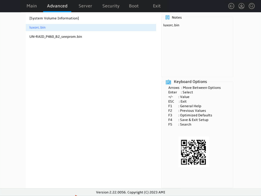
6. On the screen as shown in Figure 163, select the update file suffixed with .bin (luxor.bin in this example) and press Enter.
Figure 163 Selecting the update file
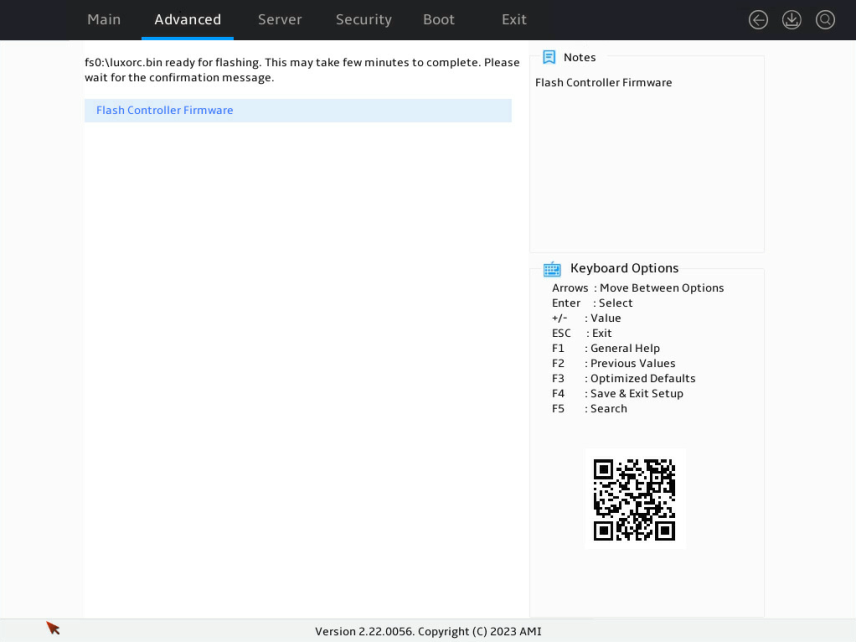
7. On the screen as shown in Figure 164, select Flash Controller Firmware and press Enter.
Figure 164 Selecting Flash Controller Firmware
8. After the update is complete, press F4 and select Yes on the dialog box that opens. The update will take effect at next startup.
Configuring IO Bypass
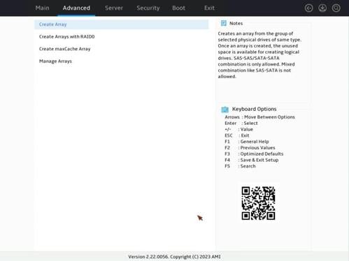
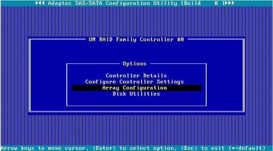
1. On the storage controller configuration screen as shown in Figure 165, select Array Configuration and press Enter.
Figure 165 Storage controller configuration screen
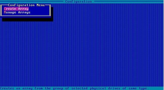
2. On the screen as shown in Figure 166, select Create Array, and press Enter.
Figure 166 Array Configuration screen
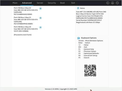
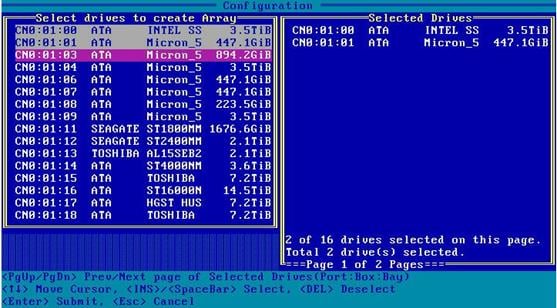
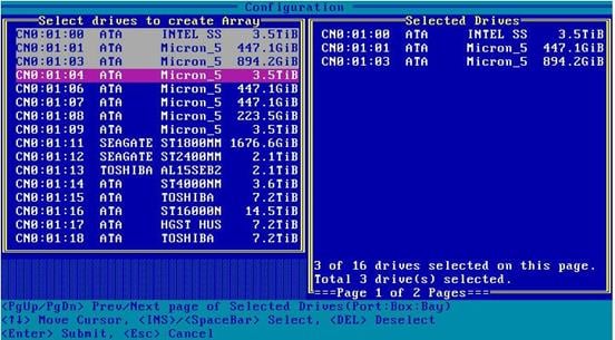
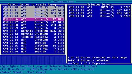
3. On the screen as shown in Figure 167, select drives to be used, which indicate by Enabled, and select [Proceed to next Form]. Then, press Enter.

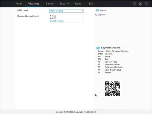
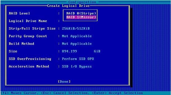
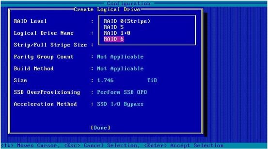
4. On the screen as shown in Figure 168, set the RAID level for RAID Level and select [Proceed to next Form]. Then, press Enter.
Figure 168 Setting the RAID level

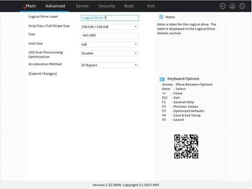
5. On the screen as shown in Figure 169, select Acceleration Method and set the logical drive cache mode. Then, press Enter.
Figure 169 Configuring the related parameters
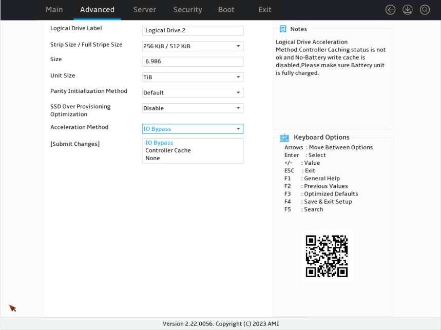
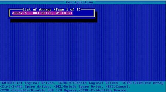
6. On the screen as shown in Figure 170, select IO Bypass and complete other RAID settings.
|
|
NOTE: This feature is only available when you selecting SSDs to build a RAID. |
Figure 170 Selecting IO Bypass
Forcing logical drives to come online
If the number of offline drives exceeds the tolerance range of the logical drive fault-tolerant method, the management tool interface will display the logical drive state as Failed. In this case, you can use the Force Online function to force the logical drives to come online. The Force Online function for storage controllers is named Re-Enable in UEFI boot mode.
|
|
CAUTION: · Forcing a logical drive in Failed state to come online might cause the existing data on the logical drive to become invalid or unrecoverable. You can reformat and use the logical drive in the OS. · The Force Online operation might change data a logical drive. Before performing this operation, make sure you fully understand the impact. |
To force logical drives to come online:
1. On the storage controller configuration screen as shown in Figure 171, for example, RAID-P460-M2, select Array Configuration and press Enter.
Figure 171 Storage controller configuration screen

2. On the screen as shown in Figure 172, select Manage Arrays and press Enter.
Figure 172 Array Configuration screen
3. On the screen as shown in Figure 173, select an array that has failed due to offline drives and press Enter.
Figure 173 Manage Arrays screen
4. On the screen as shown in Figure 174, select List Logical Drives and press Enter.
Figure 174 Screen for a failed array due to offline drives
5. On the screen as shown in Figure 175, select a logical drive in Failed state and press Enter.
Figure 175 List Logical Drives screen

6. On the screen as shown in Figure 176, select Re-Enable Logical Drives and press Enter.
Figure 176 Screen for logical drives in Failed state

Setting the number of OS bootable drives in Legacy BIOS mode
Perform this task to set the number of OS bootable drives in UEFI or Legacy mode, in the range of 0 to 8. This feature is available only in Legacy BIOS mode.
|
|
CAUTION: If the number of OS bootable drives is set to 0 in Legacy BIOS mode, the OS will start up properly, and the OS boot option are not visible. |
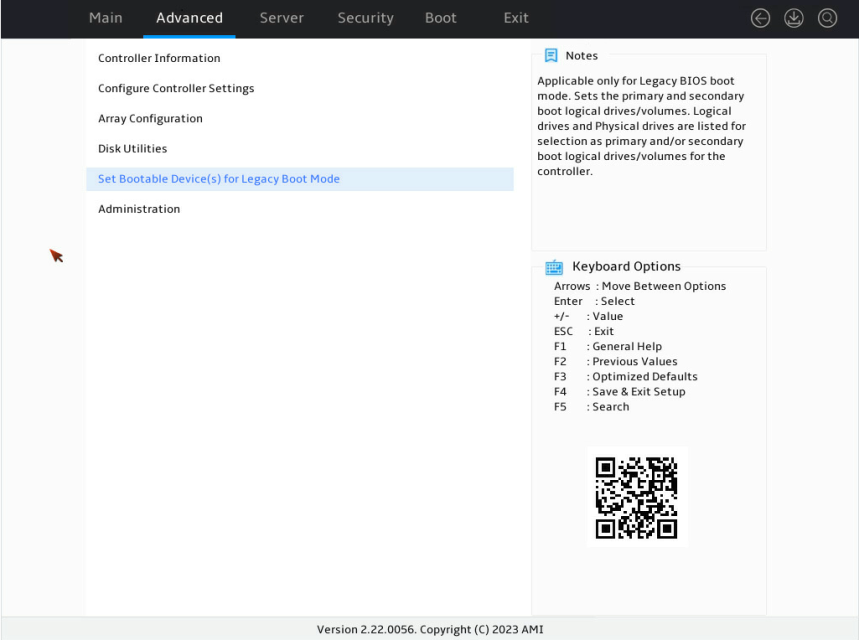
1. On the storage controller configuration screen as shown in Figure 177, select Set Bootable Device(s) for Legacy Boot Mode and press Enter.
Figure 177 Storage controller configuration screen
2. On the screen as shown in Figure 178, select Number of OS bootable drives and press Enter.
Figure 178 Set Bootable Device(s) for Legacy Boot Mode screen
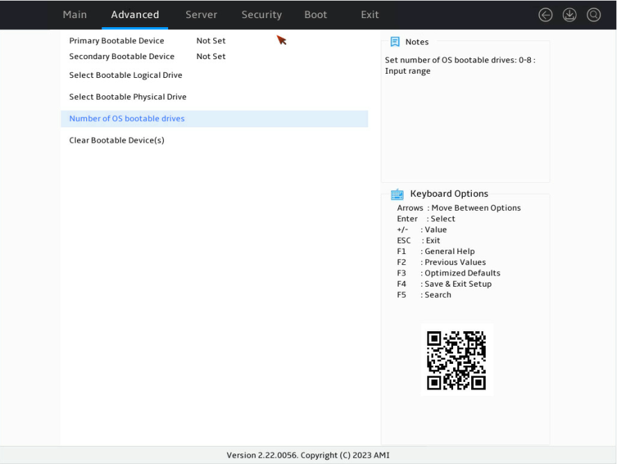
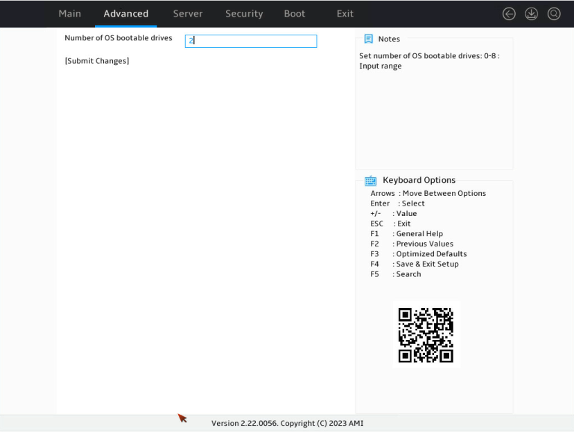
3. On the screen as shown in Figure 179, select Number of OS bootable drives, set the number of drives, and press Enter.
Figure 179 Setting the number of OS bootable drives
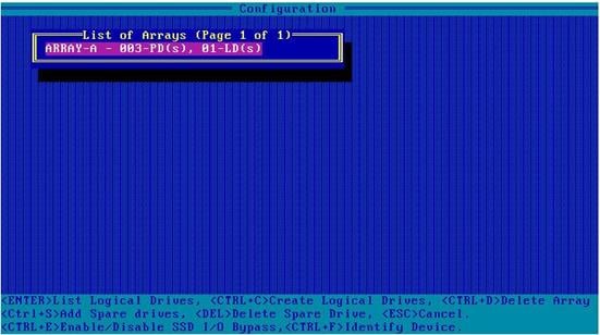
Viewing RAID controller attributes
1. On the storage controller configuration screen, select Array Configuration > Manage Arrays, and then press Enter. Select the target RAID array, and then press Enter.
Figure 180 Selecting the target RAID array
2. Select List Logical Drives and press Enter.
Figure 181 Selecting List Logical Drives
3. Select Logical Drive 1 and press Enter.
Figure 182 Selecting Logical Drive 1
4. Select Logical Drive Details and press Enter to view detailed information about the logical drive (including the logical drive name, level, and member drives).
Figure 183 Selecting Logical Drive Details

Adding multiple virtual drives (VDs)
1. Access the storage controller configuration screen.
2. Select Array Configuration and press Enter.
Figure 184 Storage controller configuration screen

3. Select Manage Arrays and press Enter.
Figure 185 Array Configuration screen

4. Select the target RAID array, and then press Enter.
Figure 186 Selecting the target VD

5. Select Create Logical Drive and Enter.
Figure 187 Selecting Create Logical Drive
6. Select the RAID level, and set the strip size and capacity.
Figure 188 Create Logical Drive screen
Configuring RAID arrays in legacy mode
This section describes how to configure RAID arrays through a storage controller in legacy mode. For more information about how to enter the BIOS and set the boot mode to legacy, see the BIOS user guide for the server.
RAID array configuration tasks at a glance
To configure RAID arrays in legacy mode, perform the following tasks:
· Accessing the storage controller configuration screen
· Switching the operating mode
· (Optional.) Configuring hot spare drives
· (Optional.) Configuring the primary boot drive
· (Optional.) Deleting a RAID array
· (Optional.) Viewing drive information
· (Optional.) Locating drives
· (Optional.) Erasing drives
· (Optional.) Modifying storage controller settings
· (Optional.) Clearing storage controller configuration
Accessing the storage controller configuration screen
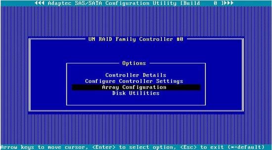
During server POST as shown in Figure 189, press Ctrl+A.
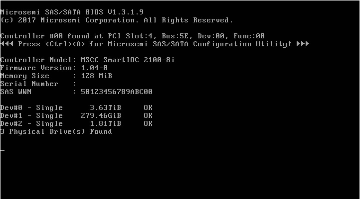
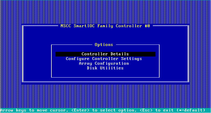
The storage controller configuration screen opens as shown in Figure 190. You can view basic RAID array status and version information on the storage controller configuration screen.
Figure 190 Storage controller configuration screen
Switching the operating mode
1. On the storage controller configuration screen as shown in Figure 191, select Configure Controller Settings and press Enter.
Figure 191 Storage controller configuration screen
2. On the screen as shown in Figure 192, select Configure Controller Port Mode and press Enter.
Figure 192 Configure Controller Settings screen
3. On the screen as shown in Figure 193, change the operating mode for Port CN0 or Port CN1 as needed.
Figure 193 Configure Controller Port Mode screen

Configuring RAID 0
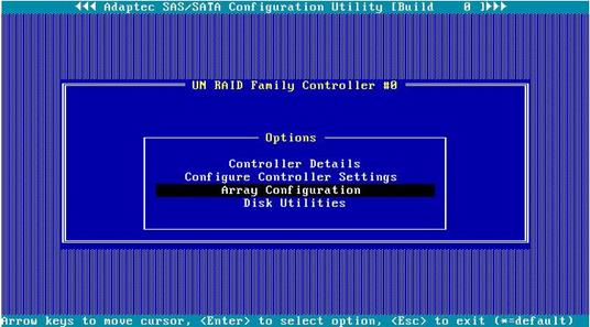
1. On the storage controller configuration screen as shown in Figure 194, select Array Configuration and press Enter.
Figure 194 Storage controller configuration screen
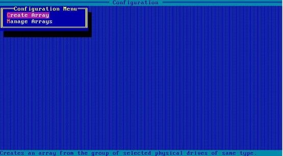
2. On the screen as shown in Figure 195, select Create Array and press Enter.
Figure 195 Array Configuration screen

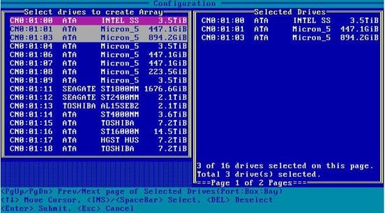
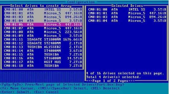
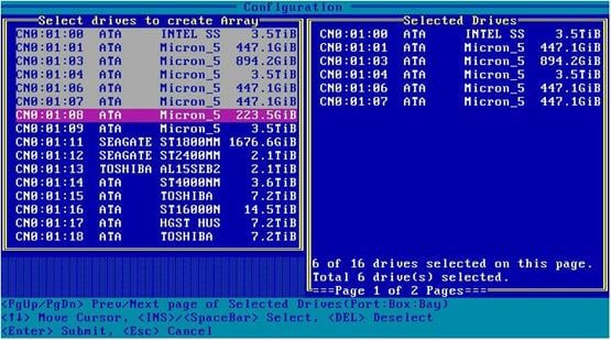
3. On the screen as shown in Figure 196, navigate to the target drive and press Insert or the space bar to select it. Repeat this step to add more drives, and press Enter.
Figure 196 Selecting the target drive
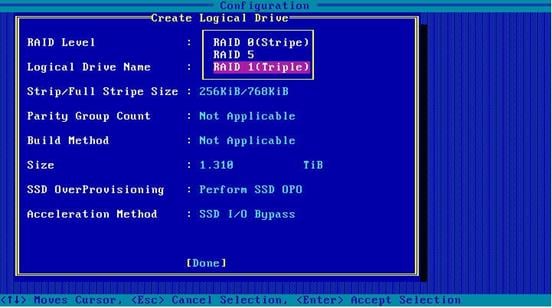
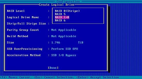
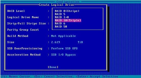
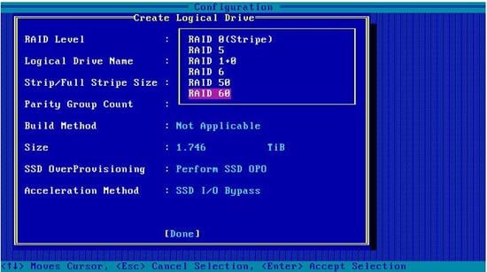
4. On the screen as shown in Figure 197, set the values for RAID Level, Logical Drive Name, Strip/Full Stripe Size, Parity Group Count, Build Method, Size, and Acceleration Method. Then, select Done and then press Enter. For more information about the parameter description, see Table 6.
Figure 197 Configuring RAID 0 parameters
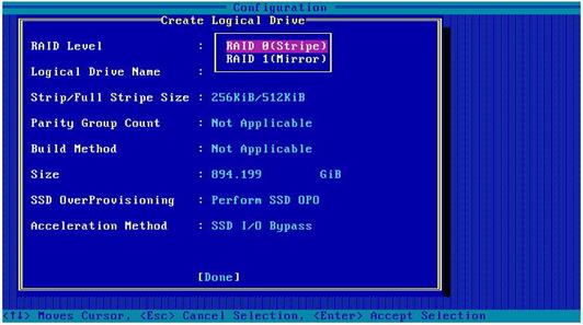
|
Parameter |
Description |
|
RAID Level |
The RAID level determines the drive performance, fault tolerance capability, and logical drive capacity. |
|
Logical Drive Name |
RAID array name. |
|
Strip/Full Stripe Size |
Data block size for each drive. |
|
Parity Group Count |
Number of RAID 1 or RAID 5 groups used to create RAID 10 or RAID 50. |
|
Build Method |
Method used to create the RAID array. |
|
Size |
Capacity for the RAID array. |
|
Acceleration Method |
Logical drive acceleration method. |
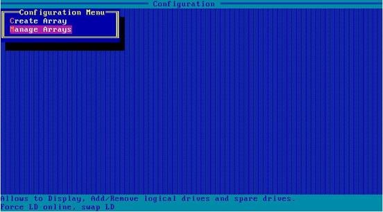
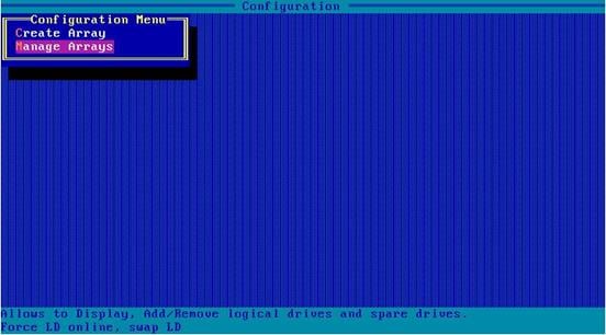
5. On the screen as shown in Figure 198, select Manage Arrays and press Enter.
Figure 198 Selecting Manage Arrays
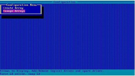
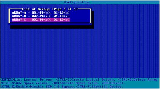
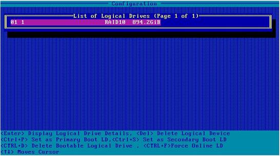
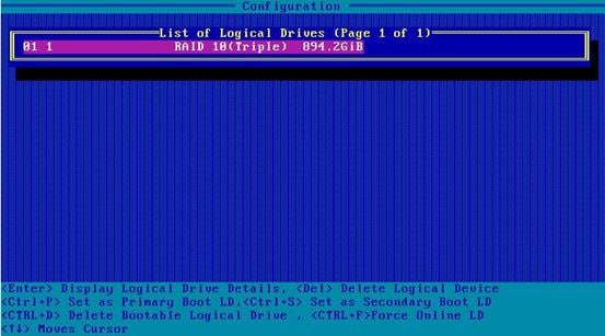
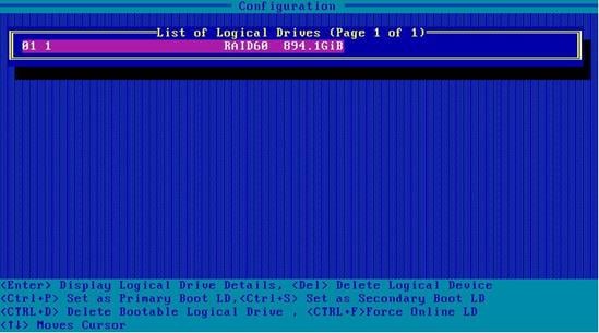
6. On the screen as shown in Figure 199, select the RAID array you want to view and press Enter to view detailed information about the RAID array (including RAID array name, level, and drive information).
Figure 199 Selecting the target RAID array
Configuring RAID 1
1. On the storage controller configuration screen as shown in Figure 200, select Array Configuration and press Enter.
Figure 200 Storage controller configuration screen
2. Select Create Array and press Enter.
Figure 201 Array Configuration screen

3. Navigate to the target drive and press Insert or the space bar to select it. Repeat this step to add more drives, and press Enter.
4. Set the values for RAID Level, Logical Drive Name, Strip/Full Stripe Size, Parity Group Count, Build Method, Size, and Acceleration Method. Then, select Done and then press Enter. For more information about the parameter description, see Table 6.
Figure 203 Configuring RAID 1 parameters
5. Select Manage Arrays and press Enter.
Figure 204 Selecting Manage Arrays
6. Select the target RAID array and press Enter to view detailed information about the RAID array (including RAID array name, level, and drive information).
Figure 205 Selecting the target RAID array
Configuring RAID 1 ADM
1. On the storage controller configuration screen as shown in Figure 206, select Array Configuration and press Enter.
Figure 206 Storage controller configuration screen
2. Select Create Array and press Enter.
Figure 207 Array Configuration screen
3. Navigate to the target drive and press Insert or the space bar to select it. Repeat this step to add more drives, and press Enter.
4. Set the values for RAID Level, Logical Drive Name, Strip/Full Stripe Size, Parity Group Count, Build Method, Size, and Acceleration Method. Then, select Done and then press Enter. For more information about the parameter description, see Table 6.
Figure 209 Configuring RAID1 ADM parameters
5. Select Manage Arrays and press Enter.
Figure 210 Selecting Manage Arrays

6. Select the target RAID array and press Enter to view detailed information about the RAID array (including RAID array name, level, and drive information).
Figure 211 Selecting the target RAID array
Configuring RAID 5
1. On the storage controller configuration screen as shown in Figure 212, select Array Configuration and press Enter.
Figure 212 Storage controller configuration screen
2. Select Create Array and press Enter.
Figure 213 Array Configuration screen
3. Navigate to the target drive and press Insert or the space bar to select it. Repeat this step to add more drives, and press Enter.
4. Set the values for RAID Level, Logical Drive Name, Strip/Full Stripe Size, Parity Group Count, Build Method, Size, and Acceleration Method. Then, select Done and then press Enter. For more information about the parameter description, see Table 6.
Figure 215 Configuring RAID5 parameters

5. Select Manage Arrays and press Enter.
Figure 216 Selecting Manage Arrays
6. Select the target RAID array and press Enter to view detailed information about the RAID array (including RAID array name, level, and drive information).
Figure 217 Selecting the target RAID array
Configuring RAID 6
1. On the storage controller configuration screen as shown in Figure 218, select Array Configuration and press Enter.
Figure 218 Storage controller configuration screen
2. Select Create Array and press Enter.
Figure 219 Array Configuration screen
3. Navigate to the target drive and press Insert or the space bar to select it. Repeat this step to add more drives, and press Enter.
4. Set the values for RAID Level, Logical Drive Name, Strip/Full Stripe Size, Parity Group Count, Build Method, Size, and Acceleration Method. Then, select Done and then press Enter. For more information about the parameter description, see Table 6.
Figure 221 Configuring RAID6 parameters
5. Select Manage Arrays and press Enter.
Figure 222 Selecting Manage Arrays

6. Select the target RAID array and press Enter to view detailed information about the RAID array (including RAID array name, level, and drive information).
Figure 223 Selecting the target RAID array
Configuring RAID 10
1. On the storage controller configuration screen as shown in Figure 224, select Array Configuration and press Enter.
Figure 224 Storage controller configuration screen
2. Select Create Array and press Enter.
Figure 225 Array Configuration screen
3. Navigate to the target drive and press Insert or the space bar to select it. Repeat this step to add more drives, and press Enter.
4. Set the values for RAID Level, Logical Drive Name, Strip/Full Stripe Size, Parity Group Count, Build Method, Size, and Acceleration Method. Then, select Done and then press Enter. For more information about the parameter description, see Table 6.
Figure 227 Configuring RAID10 parameters
5. Select Manage Arrays and press Enter.
Figure 228 Selecting Manage Arrays
6. Select the target RAID array and press Enter to view detailed information about the RAID array (including RAID array name, level, and drive information).
Figure 229 Selecting the target RAID array
Configuring RAID 10 ADM
1. On the storage controller configuration screen as shown in Figure 230, select Array Configuration and press Enter.
Figure 230 Storage controller configuration screen
2. Select Create Array and press Enter.
Figure 231 Array Configuration screen
3. Navigate to the target drive and press Insert or the space bar to select it. Repeat this step to add more drives, and press Enter.
4. Set the values for RAID Level, Logical Drive Name, Strip/Full Stripe Size, Parity Group Count, Build Method, Size, and Acceleration Method. Then, select Done and then press Enter. For more information about the parameter description, see Table 6.
Figure 233 Configuring RAID10 ADM parameters
5. Select Manage Arrays and press Enter.
Figure 234 Selecting Manage Arrays

6. Select the target RAID array and press Enter to view detailed information about the RAID array (including RAID array name, level, and drive information).
Figure 235 Selecting the target RAID array
Configuring RAID 50
1. On the storage controller configuration screen as shown in Figure 236, select Array Configuration and press Enter.
Figure 236 Storage controller configuration screen
2. Select Create Array and press Enter.
Figure 237 Array Configuration screen
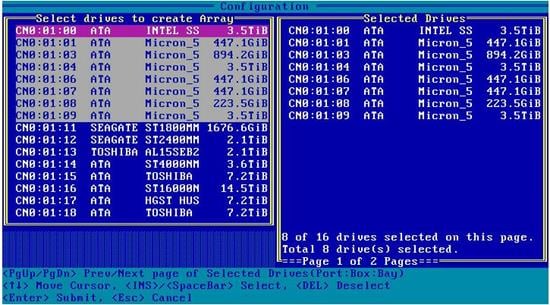
3. Navigate to the target drive and press Insert or the space bar to select it. Repeat this step to add more drives, and press Enter.
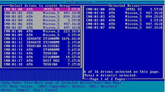
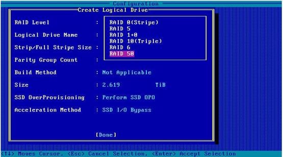
4. Set the values for RAID Level, Logical Drive Name, Strip/Full Stripe Size, Parity Group Count, Build Method, Size, and Acceleration Method. Then, select Done and then press Enter. For more information about the parameter description, see Table 6.
Figure 239 Configuring RAID50 parameters
5. Select Manage Arrays and press Enter.
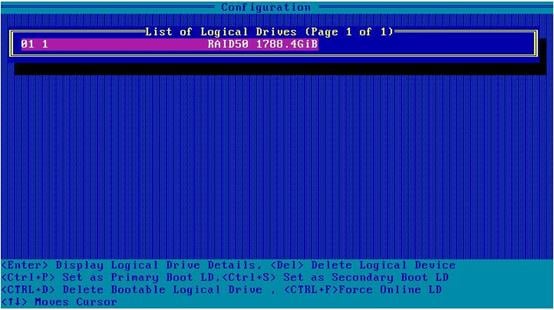
Figure 240 Selecting Manage Arrays
6. Select the target RAID array and press Enter to view detailed information about the RAID array (including RAID array name, level, and drive information).
Figure 241 Selecting the target RAID array
Configuring RAID 60
1. On the storage controller configuration screen as shown in Figure 242, select Array Configuration and press Enter.
Figure 242 Storage controller configuration screen
2. Select Create Array and press Enter.
Figure 243 Array Configuration screen

3. Navigate to the target drive and press Insert or the space bar to select it. Repeat this step to add more drives, and press Enter.
4. Set the values for RAID Level, Logical Drive Name, Strip/Full Stripe Size, Parity Group Count, Build Method, Size, and Acceleration Method. Then, select Done and then press Enter. For more information about the parameter description, see Table 6.
Figure 245 Configuring RAID60 parameters
5. Select Manage Arrays and press Enter.
Figure 246 Selecting Manage Arrays

6. Select the target RAID array and press Enter to view detailed information about the RAID array (including RAID array name, level, and drive information).
Figure 247 Selecting the target RAID array
Configuring hot spare drives
Restrictions and guidelines
In legacy mode, if a hot spare drive is configured for a RAID array, the hot spare drive will not take effect on other RAID arrays. To avoid this problem, configure all RAID arrays and then add hot spare drives.
Procedure
1. On the storage controller configuration screen as shown in Figure 248, select Array Configuration and press Enter.
Figure 248 Storage controller configuration screen

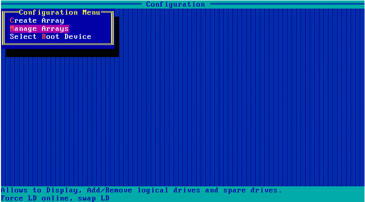
2. On the screen as shown in Figure 249, select Manage Arrays and press Enter.
Figure 249 Array Configuration screen
3. On the screen as shown in Figure 250, select the target array and press Ctrl+S.
Figure 250 Selecting the target array

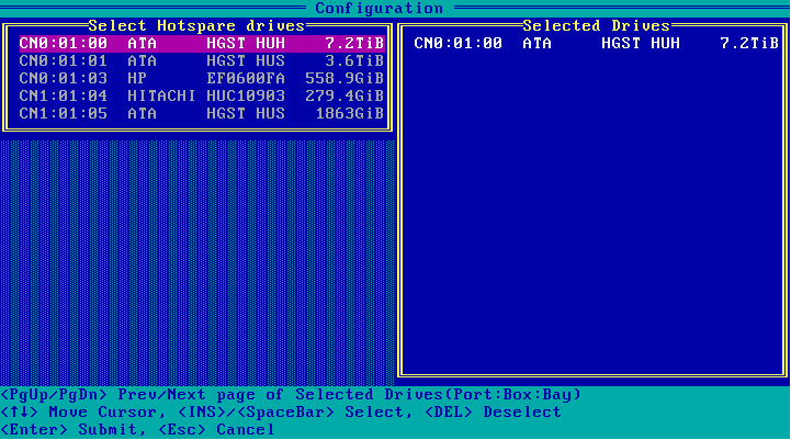
4. On the screen as shown in Figure 251, navigate to the target drive and press Insert or the space bar to select it. Repeat this step to add more drives, and press Enter.
Figure 251 Selecting the target drives
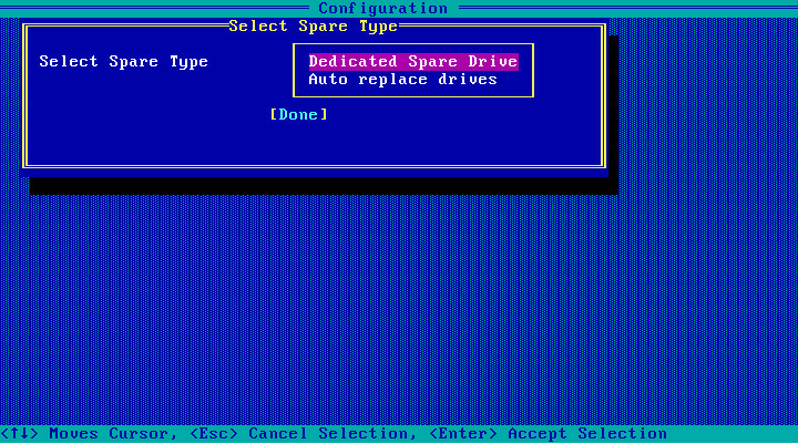
5. On the screen as shown in Figure 252, select the spare type, select Done, and then press Enter.
Figure 252 Selecting the spare type
Configuring the primary boot drive
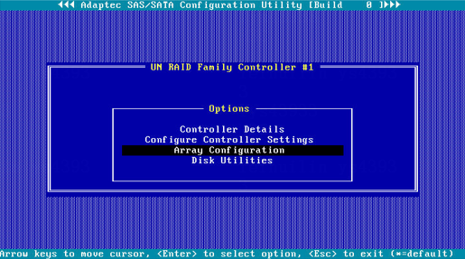
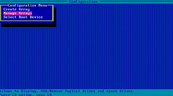
Configuring a physical drive as the primary boot drive
1. On the storage controller configuration screen as shown in Figure 253, select Array Configuration and press Enter.
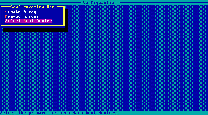
Figure 253 Storage controller configuration screen

2. On the screen as shown in Figure 254, select Select Boot Device and press Enter.
Figure 254 Array Configuration screen
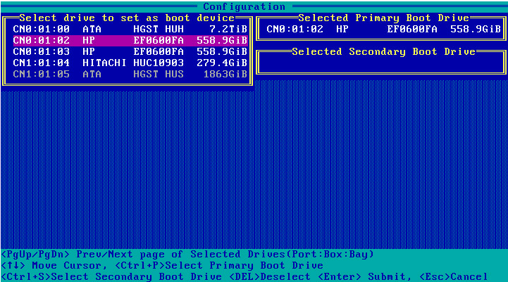
3. On the screen as shown in Figure 255, select the target drive, press Ctrl+P, and then press Enter.
Figure 255 Selecting the target drive
Configuring a logical drive as the primary boot drive
1. On the storage controller configuration screen, select Array Configuration and press Enter.
2. On the screen as shown in Figure 256, select Manage Arrays and press Enter.
Figure 256 Array Configuration screen

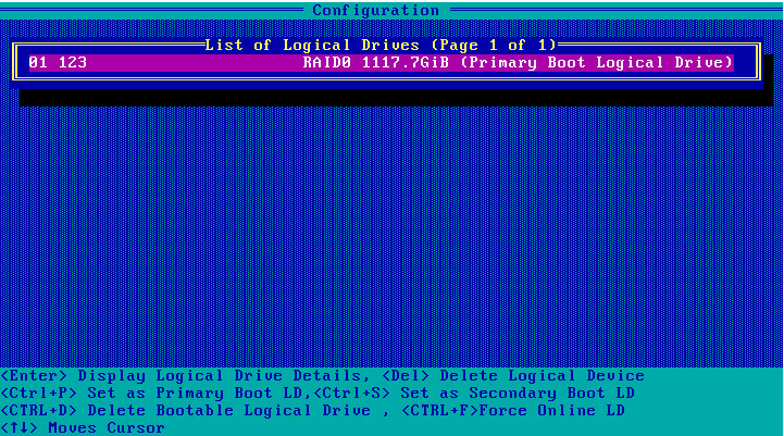
3. On the screen as shown in Figure 257, select the target RAID array and press Enter.
Figure 257 Selecting the target RAID array

4. On the screen as shown in Figure 258, press Ctrl+P to configure the RAID array as the primary boot drive.
Figure 258 Configuring the primary boot drive
Deleting a RAID array
1. Access the storage controller configuration screen.
2. On the storage controller configuration screen as shown in Figure 259, select Array Configuration and press Enter.
Figure 259 Storage controller configuration screen
3. On the screen as shown in Figure 260, select Manage Arrays and press Enter.
Figure 260 Array Configuration screen

4. On the screen as shown in Figure 261, select the target array, press Enter, and then press Delete to delete the array.
Figure 261 Deleting the target array
Viewing drive information
1. Access the storage controller configuration screen.
2. On the storage controller configuration screen as shown in Figure 262, select Disk Utilities and press Enter.
Figure 262 Storage controller configuration screen
3. On the screen as shown in Figure 263, you can see information about all available drives.
Locating drives
1. Select the target drive on the screen as shown in Figure 263 and press Enter.
2. On the screen as shown in Figure 264, select Identify Drive and press Enter. The Fault/UID LED on the drive turns steady blue.
Figure 264 Identifying the device
Erasing drives
Procedure
1. On the storage controller configuration screen as shown in Figure 263, select the drive to be erased, and then press Enter.
2. On the screen as shown in Figure 265, select Secure Erase and then press Enter.
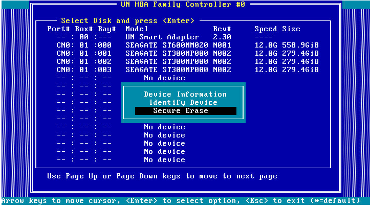
3. On the screen as shown in Figure 266, select Yes, and press Enter.
Figure 266 Confirming the operation

Modifying storage controller settings
1. Access the storage controller configuration screen.
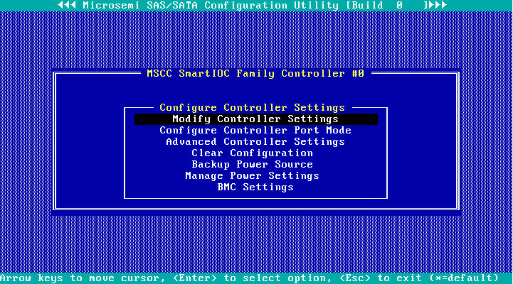
2. On the storage controller configuration screen as shown in Figure 267, select Configure Controller Settings and press Enter.
Figure 267 Storage controller configuration screen

3. On the screen as shown in Figure 268, select Modify Controller Settings and press Enter.
Figure 268 Configure Controller Settings screen
4. On the screen as shown in Figure 269, you can view the storage controller settings.
Figure 269 Modify Controller Settings screen
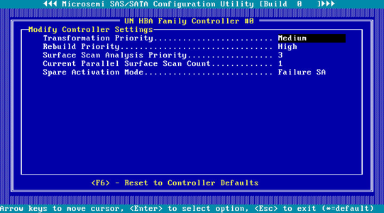
5. Press F6 to restore the storage controller settings to the default.
|
|
NOTE: The settings (such as Transformation Priority and Rebuild Priority) on the screen as shown in Figure 269 are configurable, but the default values are typically used. |
Clearing storage controller configuration
1. Access the storage controller configuration screen.
2. On the storage controller configuration screen as shown in Figure 270, select Configure Controller Settings and press Enter.
Figure 270 Storage controller configuration screen

3. On the screen as shown in Figure 271, select Clear Configuration and press Enter.
Figure 271 Configure Controller Settings screen
4. On the screen as shown in Figure 272, select Delete All Array Configurations or Delete RIS on All Physical drives and press Enter. In the confirmation dialog box that opens, select Yes and press Enter. This example selects Delete All Array Configurations.
Figure 272 Clearing storage controller configuration
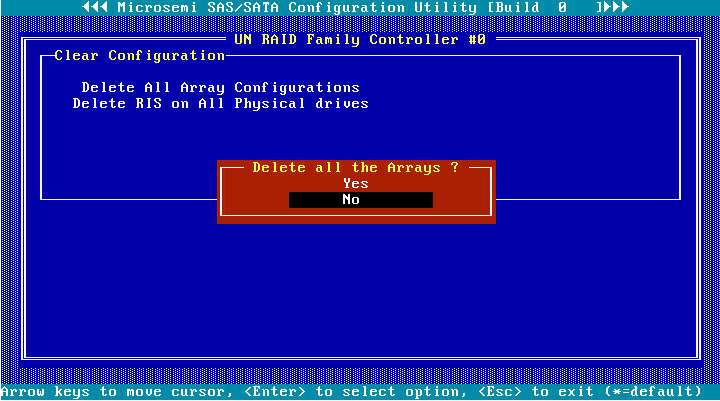
Table 7 Parameter description
|
Parameter |
Description |
|
Delete All Array Configurations |
Clear all created RAID configuration and the related array configuration. |
|
Delete RIS on All Physical drives |
Clear all invalid RAID information remaining in the physical drives. |
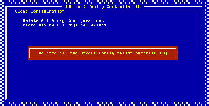
The screen as shown in Figure 273 opens, indicating that the clearing operation is complete.
Figure 273 Clearing completion
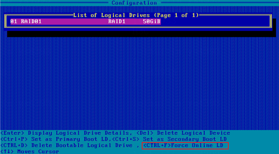
Forcing logical drives to come online
If the number of offline drives exceeds the tolerance range of the logical drive fault-tolerant method, the management tool interface will display the logical drive state as Failed. In this case, you can use the Force Online function to force the logical drives to come online. The Force Online function for storage controllers is named Force Online LD in Legacy mode boot mode.
|
|
CAUTION: · Forcing a logical drive in Failed state to come online might cause the existing data on the logical drive to become invalid or unrecoverable. You can reformat and use the logical drive in the OS. · The Force Online operation might change data a logical drive. Before performing this operation, make sure you fully understand the impact. |
To force logical drives to come online:
1. On the storage controller configuration screen as shown in Figure 274, for example, RAID-P460-M2, select Array Configuration and press Enter.
Figure 274 Storage controller configuration screen
2. On the screen as shown in Figure 275 select Manage Arrays and press Enter.
Figure 275 Array Configuration screen
3. On the screen as shown in Figure 276, select an array that has failed due to offline drives and press Enter.
Figure 276 Manage Arrays screen

4. On the screen as shown in Figure 277, select a RAID array in Failed state, press Enter, and then press Ctrl+F.
Figure 277 Screen for a failed array due to offline drives
Setting the number of OS bootable drives in Legacy BIOS mode
Perform this task to set the number of OS bootable drives in UEFI or Legacy mode, in the range of 0 to 8. This feature is available only in Legacy BIOS mode.
|
|
CAUTION: If the number of OS bootable drives is set to 0 in Legacy BIOS mode, the OS will start up properly, and the OS boot option are not visible. |
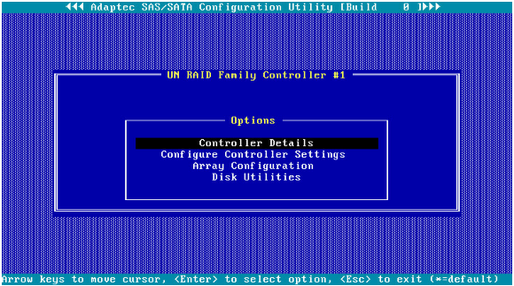
5. On the storage controller configuration screen as shown in Figure 278, for example, RAID-P460-M2, select Controller Details and press Enter.
Figure 278 Storage controller configuration screen
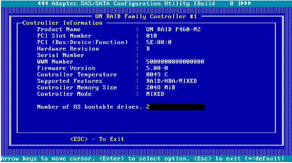
6. On the screen as shown in Figure 279, select Number of OS bootable drives, set the number of drives, and press Enter.
Figure 279 Setting the number of OS bootable drives
Downloading and installing ARCCONF
This section introduces the download and installation steps of the OS command line tool. You can use the OS command line tool to manage storage controllers during normal server operation without restarting the server.
Downloading ARCCONF
2. Download the installation package and release notes for the corresponding storage controller firmware as instructed.
3. Decompress the installation package to obtain the ARCCONF tool package for different operating systems.
Installing ARCCONF
See the release notes to install ARCCONF for the corresponding operating system.
Commonly-used commands in ARCCONF
This section describes the usage and examples of commonly used commands in ARCCONF. You can use ARCCONF commands to manage storage controllers during normal server operation without restarting the server.
Upgrade the storage controller firmware
Perform this task to upgrade the storage controller firmware.
Syntax
arcconf romupdate controller_id fwfile
Parameters
controller_id: Specifies the ID of the storage controller.
fwfile: Specifies the name of the firmware file.
Examples
# Upgrade the storage controller firmware.
[root@localhost home]# arcconf romupdate 1 luxorc.bin
Controllers found: 1
Are you sure you want to continue?
Press y, then ENTER to continue or press ENTER to abort: y
Updating controller 1 firmware...
Succeeded
You must restart the system for firmware updates to take effect.
Command completed successfully.
View basic information about a storage controller
Perform this task to view basic information about a storage controller.
Syntax
arcconf list controller_id
Parameters
controller_id: Specifies the ID of the storage controller.
Examples
# View attributes of storage controller 1.
[root@localhost home]# arcconf list 1
Controllers found: 1
----------------------------------------------------------------------
Controller information
----------------------------------------------------------------------
Controller ID : Status, Slot, Mode, Name, SerialNumber, WWN
----------------------------------------------------------------------
Controller 1: : Optimal, Slot 19, Mixed, UN RAID P460-B2, UNKNOWN, 598F181BA1DBB000
----------------------------------------------------------------------
Array Information
----------------------------------------------------------------------
Array ID : Status (Interface, TotalSize MB, FreeSpace MB)
----------------------------------------------------------------------
Array 0 : Ok (SATA SSD, 915725 MB, 0 MB)
----------------------------------------------------------------------
Logical device information
----------------------------------------------------------------------
Logical ID : Status (RAID, Interface, Size MB) Name
----------------------------------------------------------------------
Logical 0 : Optimal (1, Data, 457830 MB) LogicalDrv 0
----------------------------------------------------------------------
maxCache information
----------------------------------------------------------------------
No maxCache device created
----------------------------------------------------------------------
Physical Device information
----------------------------------------------------------------------
Physical ID : State (Interface, BlockSize, SizeMB, Vendor, Model, Type) WWN, [Location]
----------------------------------------------------------------------
Physical 0,8 : Online (SATA, 512 Bytes, 457862MB, ATA , INTEL SSDSC2KB480G8 , Solid State Drive) 500E004AAAAAAA00, [Enclosure 1, Slot 0(Connector 0:CN0)]
Physical 0,9 : Online (SATA, 512 Bytes, 457862MB, ATA , INTEL SSDSC2KB480G8 , Solid State Drive) 500E004AAAAAAA01, [Enclosure 1, Slot 1(Connector 0:CN0)]
Physical 0,10 : Ready (SATA, 512 Bytes, 457862MB, ATA , INTEL SSDSC2KB480G8 , Solid State Drive) 500E004AAAAAAA02, [Enclosure 1, Slot 2(Connector 0:CN0)]
Physical 0,11 : Ready (SATA, 512 Bytes, 457862MB, ATA , INTEL SSDSC2KB480G8 , Solid State Drive) 500E004AAAAAAA03, [Enclosure 1, Slot 3(Connector 0:CN0)]
Physical 0,12 : Ready (SATA, 512 Bytes, 457862MB, ATA , INTEL SSDSC2KB480G8 , Solid State Drive) 500E004AAAAAAA04, [Enclosure 1, Slot 4(Connector 0:CN0)]
Physical 0,13 : Ready (SATA, 512 Bytes, 457862MB, ATA , INTEL SSDSC2KB480G8 , Solid State Drive) 500E004AAAAAAA05, [Enclosure 1, Slot 5(Connector 0:CN0)]
Physical 0,14 : Ready (SATA, 512 Bytes, 457862MB, ATA , INTEL SSDSC2KB480G8 , Solid State Drive) 500E004AAAAAAA06, [Enclosure 1, Slot 6(Connector 0:CN0)]
Physical 0,15 : Ready (SATA, 512 Bytes, 457862MB, ATA , INTEL SSDSC2KB480G8 , Solid State Drive) 500E004AAAAAAA07, [Enclosure 1, Slot 7(Connector 0:CN0)]
Physical 2,0 : Ready (SES2, Not Applicable, Not Applicable, MSCC, SXP 36x12G, Enclosure Services Device) 500E004AAAAAAA7F, [Connector 0:CN0, Enclosure 1]
Physical 2,1 : Ready (SES2, Not Applicable, Not Applicable, UN , Virtual SGPIO, Enclosure Services Device) 598F181BA1DBB008, [Not Applicable]
Command completed successfully.
View physical drive, array, LD, and adapter information
Perform this task to view basic information about a storage controller.
Syntax
Table 8 View storage controller information
|
Command |
Function |
|
arcconf getconfig controller_id AD |
View adapter information. |
|
arcconf getconfig controller_id LD |
View information about all the LDs. |
|
arcconf getconfig controller_id LD LD_id |
View information about the specified LD. |
|
arcconf getconfig controller_id PD |
View information about all physical drives. |
|
arcconf getconfig controller_id PD channel_id slot_id |
View information about the specified physical drive. |
|
arcconf getconfig controller_id AR |
View information about all arrays. |
|
arcconf getconfig controller_id AR AR_id |
View information about the specified array. |
Parameters
controller_id: Specifies the ID of the storage controller.
LD_id: Specifies the ID of a LD.
channel_id: Specifies the channel ID of a drive.
slot_id: Specifies the device ID of a drive.
AR_id: Specifies the ID of an array.
Examples
# View information about all arrays.
[root@localhost ~]# arcconf getconfig 1 ar
Controllers found: 1
----------------------------------------------------------------------
Array Information
----------------------------------------------------------------------
Array Number 0
Name : A
Status : Ok
Interface : SATA SSD
Total Size : 305152 MB
Unused Size : 204800 MB
Block Size : 512 Bytes
Array Utilization : 32.77% Used, 67.23% Unused
Type : Data
Transformation Status : Not Applicable
Spare Rebuild Mode : Dedicated
SSD I/O Bypass : Disabled
--------------------------------------------------------
Array Logical Device Information
--------------------------------------------------------
Logical 0 : Optimal (1, Data, 49999 MB) LogicalDrv 0
--------------------------------------------------------
Array Physical Device Information
--------------------------------------------------------
Device 0 : Present (915715MB, SATA, SSD, Channel:0, Device:0) 18031A983BCA
Device 1 : Present (152627MB, SATA, SSD, Channel:0, Device:1) CVPR1461036N160DGN
--------------------------------------------------------
Array Hotspare Information
--------------------------------------------------------
Device 3 : Dedicated Hot-Spare (457862MB, SATA, SSD, Channel:0, Device:3) 2029E247
Command completed successfully.
[root@localhost ~]#
# View basic information about all LDs.
[root@localhost home]# arcconf getconfig 1 ld
Controllers found: 1
----------------------------------------------------------------------
Logical device information
----------------------------------------------------------------------
Logical Device number 0
Logical Device name : LogicalDrv 0
Disk Name : /dev/sdg
Block Size of member drives : 512 Bytes
Array : 0
RAID level : 1
Status of Logical Device : Optimal
Size : 457830 MB
Stripe-unit size : 256 KB
Full Stripe Size : 256 KB
Interface Type : SATA SSD
Device Type : Data
Boot Type : None
Heads : 255
Sectors Per Track : 32
Cylinders : 65535
Caching : Enabled
Mount Points : Not Mounted
LD Acceleration Method : Controller Cache
Volume Unique Identifier : 600508B1001C3F40059B7A4BF459DD3C
--------------------------------------------------------
Array Physical Device Information
--------------------------------------------------------
Device 8 : Present (457862MB, SATA, SSD, Connector:CN0, Enclosure:1, Slot:0) BTYF8316086G480BGN
Device 9 : Present (457862MB, SATA, SSD, Connector:CN0, Enclosure:1, Slot:1) BTYF95230EMQ480BGN
Command completed successfully.
# View basic information about all PDs.
[root@localhost home]# arcconf getconfig 1 pd
Controllers found: 1
----------------------------------------------------------------------
Physical Device information
----------------------------------------------------------------------
Channel #0:
Device #8
Device is a Hard drive
State : Online
Drive has stale RIS data : False
Block Size : 512 Bytes
Physical Block Size : 4K Bytes
Transfer Speed : SATA 12.0 Gb/s
Reported Channel,Device(T:L) : 0,8(8:0)
Reported Location : Enclosure 1, Slot 0(Connector 0:CN0)
Array : 0
Vendor : ATA
Model : INTEL SSDSC2KB480G8
Firmware : XCV10132
Serial number : BTYF8316086G480BGN
World-wide name : 500E004AAAAAAA00
Reserved Size : 32768 KB
Used Size : 457830 MB
Unused Size : 0 MB
Total Size : 457862 MB
S.M.A.R.T. : No
S.M.A.R.T. warnings : 0
SSD : Yes
NCQ supported : Supported
NCQ status : Enabled
Boot Type : None
Current Temperature : 27 deg C
Maximum Temperature : 49 deg C
Threshold Temperature : 73 deg C
PHY Count : 1
Drive Configuration Type : Data
Drive Exposed to OS : False
Sanitize Erase Support : True
Sanitize Lock Freeze Support : True
Sanitize Lock Anti-Freeze Support : True
Sanitize Lock Setting : None
Usage Remaining : 99 percent
Estimated Life Remaining : 39550
SSD Smart Trip Wearout : False
56 Day Warning Present : False
Drive Unique ID : 6CE08802DEF5147FA1983AF30E782771
Drive SKU Number : Not Applicable
Drive Part Number : Not Applicable
Last Failure Reason : No Failure
----------------------------------------------------------------
Device Phy Information
----------------------------------------------------------------
Phy #0
Negotiated Physical Link Rate : 12 Gbps
Negotiated Logical Link Rate : 12 Gbps
Maximum Link Rate : 6 Gbps
----------------------------------------------------------------
Device Error Counters
----------------------------------------------------------------
Aborted Commands : 0
Bad Target Errors : 0
Ecc Recovered Read Errors : 0
Failed Read Recovers : 0
Failed Write Recovers : 0
Format Errors : 0
Hardware Errors : 0
Hard Read Errors : 0
Hard Write Errors : 0
Hot Plug Count : 0
Media Failures : 0
Not Ready Errors : 0
Other Time Out Errors : 0
Predictive Failures : 0
Retry Recovered Read Errors : 0
Retry Recovered Write Errors : 0
Scsi Bus Faults : 0
Sectors Reads : 1527374224
Sectors Written : 3824871501
Service Hours : 72
Device #9
Device is a Hard drive
State : Online
Drive has stale RIS data : False
Block Size : 512 Bytes
Physical Block Size : 4K Bytes
Transfer Speed : SATA 12.0 Gb/s
Reported Channel,Device(T:L) : 0,9(9:0)
Reported Location : Enclosure 1, Slot 1(Connector 0:CN0)
Array : 0
Vendor : ATA
Model : INTEL SSDSC2KB480G8
Firmware : XCV10132
Serial number : BTYF95230EMQ480BGN
World-wide name : 500E004AAAAAAA01
Reserved Size : 32768 KB
Used Size : 457830 MB
Unused Size : 0 MB
Total Size : 457862 MB
S.M.A.R.T. : No
S.M.A.R.T. warnings : 0
SSD : Yes
NCQ supported : Supported
NCQ status : Enabled
Boot Type : None
Current Temperature : 26 deg C
Maximum Temperature : 49 deg C
Threshold Temperature : 73 deg C
PHY Count : 1
Drive Configuration Type : Data
Drive Exposed to OS : False
Sanitize Erase Support : True
Sanitize Lock Freeze Support : True
Sanitize Lock Anti-Freeze Support : True
Sanitize Lock Setting : None
Usage Remaining : 99 percent
Estimated Life Remaining : 16751
SSD Smart Trip Wearout : False
56 Day Warning Present : False
Drive Unique ID : 59BEEAC95A7A20E79FED05D090BE7939
Drive SKU Number : Not Applicable
Drive Part Number : Not Applicable
Last Failure Reason : No Failure
----------------------------------------------------------------
Device Phy Information
----------------------------------------------------------------
Phy #0
Negotiated Physical Link Rate : 12 Gbps
Negotiated Logical Link Rate : 12 Gbps
Maximum Link Rate : 6 Gbps
----------------------------------------------------------------
Device Error Counters
----------------------------------------------------------------
Aborted Commands : 0
Bad Target Errors : 0
Ecc Recovered Read Errors : 0
Failed Read Recovers : 0
Failed Write Recovers : 0
Format Errors : 0
Hardware Errors : 0
Hard Read Errors : 0
Hard Write Errors : 0
Hot Plug Count : 0
Media Failures : 0
Not Ready Errors : 0
Other Time Out Errors : 0
Predictive Failures : 0
Retry Recovered Read Errors : 0
Retry Recovered Write Errors : 0
Scsi Bus Faults : 0
Sectors Reads : 4127702025
Sectors Written : 1182791848
Service Hours : 72
Channel #2:
Device #0
Device is an Enclosure Services Device
Reported Channel,Device(T:L) : 2,0(0:0)
Reported Location : Connector 0:CN0, Enclosure 1
Active path 1
Path : CN0
Status : Ok
Active path 2
Path : CN1
Status : Ok
Enclosure ID : 1
Enclosure Logical Identifier : 500E004AAAAAAA7E
Expander ID : 0
Expander SAS Address : 500E004AAAAAAA7F
SEP device ID : 377
Type : SES2
Vendor : MSCC
Model : SXP 36x12G
Firmware : RevB
Status of Enclosure Services Device
Fan 1 status : 0 rpm (Optimal)
Fan 2 status : 0 rpm (Optimal)
Fan 3 status : 0 rpm (Optimal)
Fan 4 status : 0 rpm (Optimal)
Power supply 1 status : Optimal
Power supply 2 status : Optimal
Temperature Sensor Status 1 : Normal
Temperature Sensor Status 2 : Normal
Temperature Sensor Status 3 : Normal
Temperature Sensor Status 4 : Normal
Speaker status : Off
Channel #2:
Device #1
Device is an Enclosure Services Device
Reported Channel,Device(T:L) : 2,1(1:0)
Enclosure ID : 0
Enclosure Logical Identifier : 598F181BA1DBB008
Type : SES2
Vendor : UN
Model : Virtual SGPIO
Firmware : 4.11
Status of Enclosure Services Device
Speaker status : Not Available
Command completed successfully.
# View basic information about all ADs.
[root@localhost home]# arcconf getconfig 1 ad
Controllers found: 1
----------------------------------------------------------------------
Controller information
----------------------------------------------------------------------
Controller Status : Optimal
Controller Mode : Mixed
Channel description : SCSI
Controller Model : UN RAID P460-B2
Vendor ID : 0x9005
Device ID : 0x028F
Subsystem Vendor ID : 0x193D
Subsystem Device ID : 0xC461
Controller Serial Number : Unknown
Controller World Wide Name : 598F181BA1DBB000
Physical Slot : 19
Temperature : 44 C/ 111 F (Normal)
Host bus type : PCIe 3.0
Host bus speed : 7880 MBps
Host bus link width : 8 bit(s)/link(s)
PCI Address (Domain:Bus:Device:Function) : 0:17:0:0
Number of Ports : 2
Internal Port Count : 2
External Port Count : 0
Defunct disk drive count : 0
NCQ status : Enabled
Queue Depth : Automatic
Monitor and Performance Delay : 60 minutes
Elevator Sort : Enabled
Degraded Mode Performance Optimization : Disabled
Latency : Disabled
Statistics data collection mode : Disabled
Post Prompt Timeout : 15 seconds
Boot Controller : False
Primary Boot Volume : None
Secondary Boot Volume : None
Driver Name : smartpqi
Driver Supports SSD I/O Bypass : Yes
NVMe Supported : No
NVMe Configuration Supported : No
Manufacturing Part Number : Not Applicable
Manufacturing Spare Part Number : Not Applicable
Manufacturing Wellness Log : Not Applicable
Manufacturing SKU Number : Not Applicable
Manufacturing Model : Not Applicable
NVRAM Checksum Status : Passed
Sanitize Lock Setting : None
Expander Minimum Scan Duration : 0 seconds
Expander Scan Time-out : 350 seconds
Reboot Required Reasons : Firmware update
--------------------------------------------------------
Power Settings
--------------------------------------------------------
Power Consumption : Not Available
Current Power Mode : Maximum Performance
Pending Power Mode : Not Applicable
Survival Mode : Enabled
--------------------------------------------------------
Cache Properties
--------------------------------------------------------
Cache Status : Ok
Cache Serial Number : Not Applicable
Cache memory : 1808 MB
Read Cache Percentage : 40 percent
Write Cache Percentage : 60 percent
No-Battery Write Cache : Enabled
Wait for Cache Room : Disabled
Write Cache Bypass Threshold Size : 1040 KB
--------------------------------------------------------
Green Backup Information
--------------------------------------------------------
Backup Power Status : No Battery Connected
Battery/Capacitor Pack Count : 0
Hardware Error : No Error
--------------------------------------------------------
Physical Drive Write Cache Policy Information
--------------------------------------------------------
Configured Drives : Disabled
Unconfigured Drives : Disabled
HBA Drives : Disabled
--------------------------------------------------------
maxCache Properties
--------------------------------------------------------
maxCache Version : 4
maxCache RAID5 WriteBack Enabled : Enabled
--------------------------------------------------------
RAID Properties
--------------------------------------------------------
Logical devices/Failed/Degraded : 1/0/0
Spare Activation Mode : Failure
Background consistency check : Idle
Consistency Check Delay : 3 seconds
Parallel Consistency Check Supported : Enabled
Parallel Consistency Check Count : 1
Inconsistency Repair Policy : Disabled
Consistency Check Inconsistency Notify : Disabled
Rebuild Priority : High
Expand Priority : Medium
--------------------------------------------------------
Controller Version Information
--------------------------------------------------------
Firmware : 4.11
Driver : Linux 1.2.10-025
Hardware Revision : B
--------------------------------------------------------
Temperature Sensors Information
--------------------------------------------------------
Sensor ID : 0
Current Value : 30 deg C
Max Value Since Powered On : 31 deg C
Location : Inlet Ambient
Sensor ID : 1
Current Value : 44 deg C
Max Value Since Powered On : 45 deg C
Location : ASIC
Sensor ID : 2
Current Value : 39 deg C
Max Value Since Powered On : 40 deg C
Location : Top
Sensor ID : 3
Current Value : 37 deg C
Max Value Since Powered On : 39 deg C
Location : Bottom
--------------------------------------------------------
Out Of Band Interface Settings
--------------------------------------------------------
OOB Interface : PBSI
Pending OOB Interface : PBSI
I2C Address : 0xDE
Pending I2C Address : 0xDE
--------------------------------------------------------
PBSI
--------------------------------------------------------
I2C Clock Speed : 400 KHZ
I2C Clock Stretching : Enabled
Pending I2C Clock Speed : 400 KHZ
Pending I2C Clock Stretching : Enabled
--------------------------------------------------------
MCTP
--------------------------------------------------------
SMBus Device Type : Not Applicable
SMBus Channel : Not Applicable
Static EIDs Use On Initialization : Not Applicable
VDM Notification : Not Applicable
Pending SMBus Device Type : Not Applicable
Pending SMBus Channel : Not Applicable
Pending Static EIDs Use On Initialization : Not Applicable
Pending VDM Notification : Not Applicable
--------------------------------------------------------
Connector information
--------------------------------------------------------
Connector #0
Connector Name : CN0
Connection Number : 0
Functional Mode : Mixed
Connector Location : Internal
SAS Address : 598F181BA1DBB000
Connector #1
Connector Name : CN1
Connection Number : 1
Functional Mode : Mixed
Connector Location : Internal
SAS Address : 598F181BA1DBB004
Command completed successfully.
Set the drive UID LED
Perform this task to turn on or turn off the UID LEDs for physical drives, logical drives, or all the drives.
Syntax
Table 9 UID management-related commands
|
Command |
Function |
|
arcconf identify controller_id device channel_id slot_id time time |
Turn on the UID LED for the specified drive for a specific length of time. |
|
arcconf identify controller_id device channel_id slot_id |
Turn on the UID LED for the specified drive. You can press any key to turn off the LED. |
|
arcconf identify controller_id all time time |
Turn on the UID LEDs for all physical drives for a specific length of time. |
|
arcconf identify controller_id all stop |
Turn off the UID LEDs for all physical drives. |
|
arcconf identify controller_id logicaldrive LD_id time time |
Turn on the UID LED for the specified LD for a specific length of time. |
|
arcconf identify controller_id logicaldrive LD_id |
Turn on the UID LED for the specified LD. You can press any key to turn off the LED. |
|
arcconf identify controller_id array array_id time time |
Turn on the UID LED for the specified array for a specific length of time. |
|
arcconf identify controller_id array array_id |
Turn on the UID LED for the specified array. You can press any key to turn off the LED. |
Parameters
controller_id: Specifies the ID of the storage controller.
LD_id: Specifies the ID of a LD.
channel_id: Specifies the channel ID of a drive.
slot_id: Specifies the device ID of a drive.
time: Specifies the time during which the LED is on, in seconds.
array_id: Specifies the ID of an array.
Examples
# Turn on the UID LED for the drive with device ID 8.
[root@localhost home]# arcconf identify 1 device 0 8
Controllers found: 1
Only devices managed by an enclosure processor may be identified
The specified device(s) is/are blinking.
Press any key to stop the blinking.
# Turn on the UID LEDs for all drives for 60 seconds.
[root@localhost home]# arcconf identify 1 all time 60
Controllers found: 1
Only devices managed by an enclosure processor may be identified
Command completed successfully.
# Turn off the UID LEDs for all drives.
[root@localhost home]# arcconf identify 1 all stop
Controllers found: 1
Command completed successfully.
# Turn on the UID LED for logical drive 0.
[root@localhost home]# arcconf identify 1 logicaldrive 0
Controllers found: 1
Only devices managed by an enclosure processor may be identified
The specified device(s) is/are blinking.
Press any key to stop the blinking.
Set the operating mode of a storage controller
Perform this task to set the operating mode of a storage controller.
Syntax
arcconf setcontrollermode controller_id mode
Parameters
controller_id: Specifies the ID of the storage controller.
mode: Specifies the operating mode of a storage controller. Options include:
· 2: Specifies the HBA mode.
· 3: Specifies the RAID mode.
· 5: Specifies the Mixed mode.
Examples
# Set the storage controller mode to RAID.
[root@localhost home]# arcconf setcontrollermode 1 0
Controllers found: 1
Changing the mode to RAID will remove access to physical drives from the operating system.
Do you want to change the controller mode setting for the configuration?
Press y, then ENTER to continue or press ENTER to abort: y
Command completed successfully.
# View the storage controller mode, that is, Controller Model parameters.
[root@localhost home]# arcconf getconfig 1 ad
Controllers found: 1
----------------------------------------------------------------------
Controller information
----------------------------------------------------------------------
Controller Status : Optimal
Controller Mode : RAID (Hide RAW)
Channel description : SCSI
Controller Model : UN RAID P460-B2
Vendor ID : 0x9005
Device ID : 0x028F
Subsystem Vendor ID : 0x193D
Subsystem Device ID : 0xC461
Controller Serial Number : Unknown
Controller World Wide Name : 598F181BA1DBB000
Physical Slot : 19
Temperature : 44 C/ 111 F (Normal)
Host bus type : PCIe 3.0
Host bus speed : 7880 MBps
Host bus link width : 8 bit(s)/link(s)
PCI Address (Domain:Bus:Device:Function) : 0:17:0:0
Number of Ports : 2
Internal Port Count : 2
External Port Count : 0
Defunct disk drive count : 0
NCQ status : Enabled
Queue Depth : Automatic
Monitor and Performance Delay : 60 minutes
Elevator Sort : Enabled
Degraded Mode Performance Optimization : Disabled
Latency : Disabled
Statistics data collection mode : Disabled
Post Prompt Timeout : 15 seconds
Boot Controller : False
Primary Boot Volume : None
Secondary Boot Volume : None
Driver Name : smartpqi
Driver Supports SSD I/O Bypass : Yes
NVMe Supported : No
NVMe Configuration Supported : No
Manufacturing Part Number : Not Applicable
Manufacturing Spare Part Number : Not Applicable
Manufacturing Wellness Log : Not Applicable
Manufacturing SKU Number : Not Applicable
Manufacturing Model : Not Applicable
NVRAM Checksum Status : Passed
Sanitize Lock Setting : None
Expander Minimum Scan Duration : 0 seconds
Expander Scan Time-out : 350 seconds
Reboot Required Reasons : Firmware update
--------------------------------------------------------
Power Settings
--------------------------------------------------------
Power Consumption : Not Available
Current Power Mode : Maximum Performance
Pending Power Mode : Not Applicable
Survival Mode : Enabled
--------------------------------------------------------
Cache Properties
--------------------------------------------------------
Cache Status : Ok
Cache Serial Number : Not Applicable
Cache memory : 1808 MB
Read Cache Percentage : 40 percent
Write Cache Percentage : 60 percent
No-Battery Write Cache : Enabled
Wait for Cache Room : Disabled
Write Cache Bypass Threshold Size : 1040 KB
--------------------------------------------------------
Green Backup Information
--------------------------------------------------------
Backup Power Status : No Battery Connected
Battery/Capacitor Pack Count : 0
Hardware Error : No Error
--------------------------------------------------------
Physical Drive Write Cache Policy Information
--------------------------------------------------------
Configured Drives : Disabled
Unconfigured Drives : Disabled
HBA Drives : Disabled
--------------------------------------------------------
maxCache Properties
--------------------------------------------------------
maxCache Version : 4
maxCache RAID5 WriteBack Enabled : Enabled
--------------------------------------------------------
RAID Properties
--------------------------------------------------------
Logical devices/Failed/Degraded : 1/0/0
Spare Activation Mode : Failure
Background consistency check : Idle
Consistency Check Delay : 3 seconds
Parallel Consistency Check Supported : Enabled
Parallel Consistency Check Count : 1
Inconsistency Repair Policy : Disabled
Consistency Check Inconsistency Notify : Disabled
Rebuild Priority : High
Expand Priority : Medium
--------------------------------------------------------
Controller Version Information
--------------------------------------------------------
Firmware : 4.11
Driver : Linux 1.2.10-025
Hardware Revision : B
--------------------------------------------------------
Temperature Sensors Information
--------------------------------------------------------
Sensor ID : 0
Current Value : 30 deg C
Max Value Since Powered On : 33 deg C
Location : Inlet Ambient
Sensor ID : 1
Current Value : 44 deg C
Max Value Since Powered On : 47 deg C
Location : ASIC
Sensor ID : 2
Current Value : 39 deg C
Max Value Since Powered On : 41 deg C
Location : Top
Sensor ID : 3
Current Value : 37 deg C
Max Value Since Powered On : 40 deg C
Location : Bottom
--------------------------------------------------------
Out Of Band Interface Settings
--------------------------------------------------------
OOB Interface : PBSI
Pending OOB Interface : PBSI
I2C Address : 0xDE
Pending I2C Address : 0xDE
--------------------------------------------------------
PBSI
--------------------------------------------------------
I2C Clock Speed : 400 KHZ
I2C Clock Stretching : Enabled
Pending I2C Clock Speed : 400 KHZ
Pending I2C Clock Stretching : Enabled
--------------------------------------------------------
MCTP
--------------------------------------------------------
SMBus Device Type : Not Applicable
SMBus Channel : Not Applicable
Static EIDs Use On Initialization : Not Applicable
VDM Notification : Not Applicable
Pending SMBus Device Type : Not Applicable
Pending SMBus Channel : Not Applicable
Pending Static EIDs Use On Initialization : Not Applicable
Pending VDM Notification : Not Applicable
--------------------------------------------------------
Connector information
--------------------------------------------------------
Connector #0
Connector Name : CN0
Connection Number : 0
Functional Mode : RAID (Hide RAW)
Connector Location : Internal
SAS Address : 598F181BA1DBB000
Connector #1
Connector Name : CN1
Connection Number : 1
Functional Mode : RAID (Hide RAW)
Connector Location : Internal
SAS Address : 598F181BA1DBB004
Command completed successfully.
Create and delete RAID arrays
Perform this task to create and delete RAID arrays.
Syntax
arcconf create controller_id logicaldrive option size level channel_id slot_id channel_id slot_id……
arcconf delete controller_id logicaldrive ld_id noprompt
Parameters
controller_id: Specifies the ID of the storage controller.
option: Specifies the LD attributes. Attributes include:
· Stripesize: Strip size of the LD.
· Legs: NPG of the LD. This attribute is available only for RAID 50 and RAID 60.
· Name: Name of the LD.
· Method: Initialization method of the LD. Options include build and default.
· Wcache: IO Bypass. This attribute is available only when maxCache is created.
· LDcache: Controller cache.
· SSDOverProvisioningOptimization: SSD attribute, which is available only when a RAID array is set by SSDs. Options include enable and disable. Enabling this option will optimize SSDs by reallocating all used blocks before writing data to the SSDs, resulting in faster initialization.
· DataLD: ID of the accelerated LD.
size: Capacity of the LD. The unit is MB. Enter only the number here. For example, if you set the value to 1024, it indicates that the driver capacity is 1024 MB. If you set the value to MAX, it indicates that all the capacity of the physical drive is used to create the logical drive.
level: Level of the LD.
channel_id: Specifies the channel ID of a drive.
slot_id: Specifies the device ID of a drive.
# Create RAID 50.
[root@localhost home]# arcconf create 1 logicaldrive stripesize 512 legs 2 name VR1 method default max 50 0 8 0 9 0 10 0 11 0 12 0 13
Controllers found: 1
Do you want to add a logical device to the configuration?
Press y, then ENTER to continue or press ENTER to abort: y
Creating logical device: VR1
Command completed successfully.
# Delete the logical drive with ID 0.
[root@localhost home]# arcconf delete 1 logicaldrive 0 noprompt
Controllers found: 1
WARNING: Deleting this logical device will automatically delete array 0 because it is the only logical device present on that array.
All data in logical device 0 will be lost.
Deleting: logical device 0 ("LogicalDrv 0")
Command completed successfully.
# Create RAID 10.
[root@localhost ~]# arcconf create 1 logicaldrive 102400 10 0 8 0 9 0 10 0 11
Controllers found: 1
Space will be wasted as devices specified are of different sizes.
WARNING: Use of SED device(s) may lead to data loss if ownership is taken on the specified device(s).
Do you want to add a logical device to the configuration?
Press y, then ENTER to continue or press ENTER to abort: y
Creating logical device: LogicalDrv 0
Command completed successfully.
# Create RAID 6.
[root@localhost ~]# arcconf create 1 logicaldrive 102400 6 0 8 0 9 0 10 0 11
Controllers found: 1
Space will be wasted as devices specified are of different sizes.
WARNING: Use of SED device(s) may lead to data loss if ownership is taken on the specified device(s).
Do you want to add a logical device to the configuration?
Press y, then ENTER to continue or press ENTER to abort: y
Creating logical device: LogicalDrv 0
Command completed successfully.
# Create RAID 0.
[root@localhost ~]# arcconf create 1 logicaldrive 102400 0 0 8 0 9 0 10 0 11
Controllers found: 1
Space will be wasted as devices specified are of different sizes.
WARNING: Use of SED device(s) may lead to data loss if ownership is taken on the specified device(s).
Do you want to add a logical device to the configuration?
Press y, then ENTER to continue or press ENTER to abort: y
Creating logical device: LogicalDrv 0
Command completed successfully.
# Create RAID 1.
[root@localhost ~]# arcconf create 1 logicaldrive 102400 1 0 8 0 9
Controllers found: 1
Space will be wasted as devices specified are of different sizes.
WARNING: Use of SED device(s) may lead to data loss if ownership is taken on the specified device(s).
Do you want to add a logical device to the configuration?
Press y, then ENTER to continue or press ENTER to abort: y
Creating logical device: LogicalDrv 0
Command completed successfully.
# Create RAID 1ADM.
[root@localhost ~]# arcconf create 1 logicaldrive 102400 1Triple 0 8 0 9 0 11
Controllers found: 1
Space will be wasted as devices specified are of different sizes.
WARNING: Use of SED device(s) may lead to data loss if ownership is taken on the specified device(s).
Do you want to add a logical device to the configuration?
Press y, then ENTER to continue or press ENTER to abort: y
Creating logical device: LogicalDrv 0
Command completed successfully.
# Create RAID 10ADM.
[root@localhost ~]# arcconf create 1 logicaldrive 102400 10Triple 0 8 0 9 0 11 0 12 0 13 0 14
Controllers found: 1
Space will be wasted as devices specified are of different sizes.
WARNING: Use of SED device(s) may lead to data loss if ownership is taken on the specified device(s).
Do you want to add a logical device to the configuration?
Press y, then ENTER to continue or press ENTER to abort: y
Creating logical device: LogicalDrv 0
Command completed successfully.
# Create RAID 5.
[root@localhost ~]# arcconf create 1 logicaldrive 102400 5 0 8 0 9 0 10
Controllers found: 1
Space will be wasted as devices specified are of different sizes.
WARNING: Use of SED device(s) may lead to data loss if ownership is taken on the specified device(s).
Do you want to add a logical device to the configuration?
Press y, then ENTER to continue or press ENTER to abort: y
Creating logical device: LogicalDrv 0
Command completed successfully.
# Create RAID 60.
[root@localhost ~]# arcconf create 1 logicaldrive 102400 60 0 8 0 9 0 10 0 11 0 12 0 13 0 14 0 15
Controllers found: 1
Space will be wasted as devices specified are of different sizes.
WARNING: Use of SED device(s) may lead to data loss if ownership is taken on the specified device(s).
Do you want to add a logical device to the configuration?
Press y, then ENTER to continue or press ENTER to abort: y
Creating logical device: LogicalDrv 0
Command completed successfully.
Scale up a logical drive
Perform this task to scale up a logical drive when member drives have capacity not used by logical drives.
Syntax
arcconf modify controller_id from LD_id to LD_size LD_level channel_id slot_id channel_id slot_id
|
|
NOTE: · To ensure a successful scale-up, make sure you have obtained the correct RAID level, channel ID, and physical ID of member drives. · Make sure the added capacity does not exceed the remaining capacity of the array in which the logical drive resides. |
Parameters
controller_id: Specifies the ID of the storage controller.
LD_id: Specifies the ID of a LD.
LD_size: Specifies the new LD capacity, in MB.
LD_level: Specifies the RAID level.
channel_id: Specifies the channel ID of a drive.
slot_id: Specifies the device ID of a drive.
Examples
# Scale up the LD capacity to 204800 MB.
[root@localhost ~]# arcconf modify 1 from 0 to 204800 1 0 0 0 1
Controllers found: 1
Reconfiguration of a logical device is a long process. Are you sure you want
to continue?
Press y, then ENTER to continue or press ENTER to abort: y
Reconfiguring logical device: LogicalDrv 0
Command completed successfully.
Add new drives to a RAID array
Perform this task to add new drives to an existing RAID array.
Syntax
arcconf modify controller_id array array_id expand channel_id slot_id channel_id slot_id......
Parameters
controller_id: Specifies the ID of the storage controller.
array_id: Specifies the ID of an array.
channel_id: Specifies the channel ID of a drive.
slot_id: Specifies the device ID of a drive.
Description
· Adding new drives to RAID 1/1ADM/10 might cause the RAID level to increase depending on the number of the added drives.
· During expansion by adding drives, you can add only one drive for RAID 0/RAID 5/RAID 6 at a time, two drives for RAID 50/RAID 60 at a time, and three drives for RAID10ADM at a time.
· After adding a drive, see "Scale up a logical drive" to scale up logical drives.
Examples
# Add new drives to the array.
[root@localhost ~]# arcconf modify 1 array 0 expand 0 10
Controllers found: 1
This will modify the array 0.
Are you sure you want to continue?
Press y, then ENTER to continue or press ENTER to abort: y
Modifying array: 0
Command completed successfully.
Migrate the RAID level
Perform this task to migrate the RAID level.
Syntax
arcconf modify controller_id from LD_id to LD_size LD_level channel_id slot_id channel_id slot_id......
Parameters
controller_id: Specifies the ID of the storage controller.
LD_id: Specifies the ID of a LD.
LD_size: Specifies the capacity of the LD before migration.
LD_level: Specifies the LD level after migration.
channel_id: Specifies the channel ID of a drive.
slot_id: Specifies the device ID of a drive.
Usage guidelines
· If the number of drives required for the target level of migration is more than the original level, you must first add drives to the LD and then perform migration. Adding new drives to RAID 1/1ADM/10 for the PMC storage controller might cause the RAID level to increase depending on the number of the added drives.
· To migrate RAID 1 to RAID 5, you cannot add drives directly to RAID 1. First migrate RAID 1 to RAID 0, add drives, and then migrate RAID 0 to RAID 5.
Examples
# Migrate RAID 0 to RAID 5.
[root@localhost ~]# arcconf modify 1 from 0 to 305190 5 0 0 0 1 0 6 0 7
Controllers found: 1
Reconfiguration of a logical device is a long process. Are you sure you want
to continue?
Press y, then ENTER to continue or press ENTER to abort: y
Reconfiguring logical device: LogicalDrv 0
Command completed successfully.
# View the migration process.
[root@localhost ~]# arcconf getconfig 1 ld
Controllers found: 1
----------------------------------------------------------------------
Logical device information
----------------------------------------------------------------------
Logical Device number 0
Logical Device name : LogicalDrv 0
Disk Name : /dev/sda
Block Size of member drives : 512 Bytes
Array : 0
RAID level : 5
Status of Logical Device : Optimal(Background Parity
Initialization : 51 %)
Parity Initialization Status : In Progress
Size : 305190 MB
Stripe-unit size : 256 KB
Full Stripe Size : 768 KB
Interface Type : SATA SSD
Device Type : Data
Boot Type : None
Heads : 255
Sectors Per Track : 32
Cylinders : 65535
Caching : Enabled
Mount Points : Not Applicable
LD Acceleration Method : Controller Cache
Volume Unique Identifier : 600508B1001C7B7C4BBF3ACB01F885BC
--------------------------------------------------------
Array Physical Device Information
--------------------------------------------------------
Device 0 : Present (152627MB, SATA, SSD,
Channel:0, Device:0) CVPR1461036N160DGN
Device 1 : Present (1526185MB, SATA, SSD,
Channel:0, Device:1) PHDV624000FL1P6EGN
Device 6 : Present (457862MB, SATA, SSD,
Channel:0, Device:6) 17501B83246B
Device 7 : Present (915715MB, SATA, SSD,
Channel:0, Device:7) 18031A983BCA
Command completed successfully.
Set the drive initialization or uninitialization state
Perform this task to set the drive initialization or uninitialization state.
Syntax
arcconf task start controller_id device channel_id device_id type
Parameters
controller_id: Specifies the ID of the storage controller.
channel_id: Specifies the channel ID of the drive. To obtain the channel ID, use the arcconf getconfig controller_id pd command. The Reported Channel and Device (T:L) fields in the output represent the channel and ID.
device_id: Specifies the drive ID. To obtain the drive ID, use the arcconf getconfig controller_id pd command. The Reported Channel and Device (T:L) fields in the output represent the channel and ID.
type: Specifies the task type. Options include initialize and uninitialize.
Usage guidelines
If you specify all as the channel_id device_id, the command initializes or uninitializes all drives managed by the storage controller.
Examples
# Set the drive with device ID 9 for storage controller 1 to initialized state.
[root@localhost ~]# arcconf task start 1 device 0 9 initialize
Controllers found: 1
Initializing Channel 0, Device 9 will erase its metadata, the section
where all the logical device definition data is stored
Are you sure you want to continue?
Press y, then ENTER to continue or press ENTER to abort: y
Initializing Channel 0, Device 9.
Command completed successfully.
Configure and delete hot spare drives for logical drives
Perform this task to configure hot spare drives for logical drives.
Syntax
To create a hot spare drive:
arcconf setstate controller_id device channel_id slot_id hsp array array_id sparetype type
To delete a hot spare drive:
arcconf setstate controller_id device channel_id slot_id rdy
Parameters
controller_id: Specifies the ID of the storage controller.
channel_id: Specifies the channel ID of the drive.
slot_id: Specifies the drive ID.
array_id: Specifies the array ID.
type: Specifies the mode of hot spare drives. Options include:
· 1: Dedicated
· 2: Autoreplace
Examples
# Configure an Autoreplace hot spare drive for a logical drive.
[root@localhost ~]# arcconf setstate 1 device 0 3
hsp array 0 sparetype 2
Controllers found: 1
Any existing hot-spare drives of a different sparetype will be removed.
The physical drive used for this operation is connected to Mixed Mode(Smart
HBA) connector. Using it will not allow operating system to use the drive
contents.
Are you sure you want to continue?
Press y, then ENTER to continue or press ENTER to abort: y
Command completed successfully.
# Delete the hot spare drive with device ID 10.
[root@localhost ~]# arcconf setstate 1 device 0 10 rdy
Controllers found: 1
Command completed successfully.
Set the mode of hot spare drives
Perform this task to set the mode of hot spare drives.
Syntax
arcconf setarrayparam controller_id array_id sparetype mode
Parameters
controller_id: Specifies the ID of the storage controller.
array_id: Specifies the array ID.
type: Specifies the mode of hot spare drives. Options include:
· 1: Dedicated
· 2: Autoreplace
Examples
# Set the mode of hot spare drives for an array to Dedicated.
[root@localhost ~]# arcconf setarrayparam 1 0 sparetype 1
Controllers found: 1
Command completed successfully.
Collect logs
Perform this task to collect storage controller logs.
Syntax
arcconf savesupportarchive path
Parameters
path: Specifies the path for storing the log file.
Examples
# Collect storage controller logs and save the log in the home directory.
[root@localhost ~]# arcconf savesupportarchive /home
Controllers found: 1
Collecting uart logs may take few seconds...
The logs are saved in relevant folders in /home/Support
Command completed successfully.
Enable or disable LD cache
Perform this task to enable or disable the LD cache feature.
Syntax
arcconf setcache controller_id logicaldrive LD_id con
arcconf setcache controller_id logicaldrive LD_id coff
Parameters
controller_id: Specifies the ID of the storage controller.
LD_id: Specifies the ID of a LD.
Examples
# Enable cache for LD 0.
[root@localhost Firmware]# arcconf setcache 1 logicaldrive 0 con
Controllers found: 1
Command completed successfully.
# Disable cache for LD 0.
[root@localhost ~]# arcconf setcache 1 logicaldrive 0 coff
Controllers found: 1
Command completed successfully.
# Set the cache write policy to write through.
[root@localhost Firmware]# arcconf setcache 1 logicaldrive 0 wt
Controllers found: 1
Command completed successfully.
# Set the cache write policy to write back.
[root@localhost Firmware]# arcconf setcache 1 logicaldrive 0 wb
Controllers found: 1
WARNING: Power failure without battery/ZMM support will lead to data loss.
Do you wish to continue?
Press y, then ENTER to continue or press ENTER to abort: y
Command completed successfully.
Erase data on a data disk
Perform this task to start or stop erasing data on a data disk.
Syntax
arcconf task start controller_id device channel_id slot_id secureerase
arcconf task stop controller_id device channel_id slot_id
Parameters
controller_id: Specifies the ID of the storage controller.
channel_id: Specifies the channel ID of a drive.
slot_id: Specifies the device ID of a drive.
Examples
# Start to erase data on the physical drive with device ID 15.
[root@localhost Firmware]# arcconf task start 1 device 0 15 secureerase
Controllers found: 1
Secure erase of a Hard drive is a long process.
Warning: Rebooting the machine would stop the Secure erase task.
Are you sure you want to continue?
Press y, then ENTER to continue or press ENTER to abort: y
Secure Erasing Channel 0, Device 15.
Command completed successfully.
# Stop erasing data on the physical drive with device ID 15.
[root@localhost Firmware]# arcconf task stop 1 device 0 15
Controllers found: 1
Command completed successfully.
Force a physical drive to go offline
Perform this task to force a physical to go offline.
Syntax
arcconf setstate controller_id device channel_id slot_id DDD
Parameters
controller_id: Specifies the ID of the storage controller.
channel_id: Specifies the channel ID of a drive.
slot_id: Specifies the device ID of a drive.
Examples
# Force the physical drive with device ID 14 to go offline.
[root@localhost ~]# arcconf setstate 1 device 0 14 DDD
Controllers found: 1
Changing state from Ready to Failed may delete any data partitions present on the drive.
Are you sure you want to continue?
Press y, then ENTER to continue or press ENTER to abort: y
Command completed successfully.
Configure consistency check
Perform this task to enable and configure consistency check.
Syntax
arcconf consistencycheck controller_id mode
arcconf consistencycheck controller_id parallelcount parallelcount_number
Parameters
controller_id: Specifies the ID of the storage controller.
channel_id: Specifies the channel ID of a drive.
slot_id: Specifies the device ID of a drive.
mode: Specifies the action. Options include:
· on: Enable consistency check.
· off: Disable consistency check.
parallelcount_number: Specifies the number of consistency check concurrencies at the back end.
Examples
# Enable consistency check and set the number of concurrencies to 4.
[root@localhost ~]# arcconf consistencycheck 1 on
Controllers found: 1
Command completed successfully.
[root@localhost ~]# arcconf consistencycheck 1 parallelcount 4
Controllers found: 1
Command completed successfully.
Upgrade the drive firmware
Perform this task to upgrade the drive firmware.
Syntax
arcconf imageupdate controller_id device channel_id slot_id chunksize fwfile mode
Parameters
controller_id: Specifies the ID of the storage controller.
channel_id: Specifies the channel ID of a drive.
slot_id: Specifies the device ID of a drive.
chunksize: Specifies the chunk size for firmware upgrade, in bytes.
fwfile: Specifies the name of the file for firmware upgrade.
mode: Specifies the upgrade mode. Options include:
· 5: Downloads and activates the image file for firmware upgrade in a single transmission.
· 7: Downloads the image file for firmware upgrade in blocks specified by the chunksize argument.
· 14: Downloads but not activate the image file for firmware upgrade in blocks specified by the chunksize argument.
· 239: Downloads and activates the image file for firmware upgrade in blocks specified by the chunksize argument.
Examples
# Upgrade the firmware for the drive with device ID 14.
[root@localhost ~]# arcconf imageupdate 1 device 0 14 32768 /home/XCV10132_XBUB0010_GEN_10001_signed.bin 7
Controllers found: 1
Updating a device with an invalid image file may render the device unusable. Please make sure you have the correct image file.
You must restart the system for firmware updates to take effect.
Are you sure you want to continue?
Press y, then ENTER to continue or press ENTER to abort: Y
Succeeded
You must restart the system for device firmware update to take effect.
Command completed successfully.
Restore the default storage controller settings
Perform this task to restore the default storage controller settings.
Syntax
arcconf setconfig controller_id default [ noprompt ]
Parameters
controller_id: Specifies the ID of the storage controller.
noprompt: Forcedly restores the default settings.
Examples
# Restore the default storage controller settings.
[root@localhost ~]# arcconf setconfig 1 default
Set the read and write cache ratios
Perform this task to set the read and write cache ratios for a storage controller.
Syntax
arcconf setcache controller_id cacheratio read write
Parameters
controller_id: Specifies the ID of the storage controller.
read: Specifies the read cache ratio in the range of 0 to 100.
write: Specifies the write cache ratio in the range of 0 to 100.
Usage guidelines
The sum of the read cache ratio and the write cache ratio must be 100.
Examples
# Set both the read cache ratio and write cache ratio to 50%.
[root@localhost ~]# arcconf setcache 1 cacheratio 50 50
Controllers found: 1
Command completed successfully.
[root@localhost ~]#
Enable or disable I/O bypass
Perform this task to enable or disable I/O bypass for all logical devices managed by a storage controller.
Syntax
arcconf setarrayparam controller_id ssdiobypass enable
arcconf setarrayparam controller_id ssdiobypass disable
Parameters
controller_id: Specifies the ID of the storage controller.
enable: Enable I/O bypass.
disable: Disable I/O bypass.
Examples
# Disable I/O bypass for controllers 1 and 0.
arcconf setarrayparam 1 0 ssdiobypass disable
Troubleshooting
For detailed information about collecting storage controller fault information, diagnosing and locating faults, and troubleshooting servers, see H3C Servers Troubleshooting Guide.
Compatibility
For information about storage controller and server compatibility, access http://www.h3c.com/en/home/qr/default.htm?id=66.
Downloading and installing drivers
Access https://www.h3c.com/en/Support/Resource_Center/EN/Severs/Catalog/Optional_Parts/Storage_Controller/?tbox=Software to download the storage controller drivers. For more information about installing drivers, see the release notes for the driver program.
