- Table of Contents
-
- H3C G6 Servers Storage Controller User Guide-6W103
- 00-Preface
- 01-Storage controller overview
- 02-Storage controller features
- 03-Configuring a VROC SATA RAID controller
- 04-Configuring an NVMe VROC module
- 05-Configuring an LSI-9540 or 9560 storage controller
- 06-Configuring an LSI-9660 series storage controller
- 07-Configuring a P460, P2404 or P4408 storage controller
- 08-Configuring an LSI 9500 series storage controller
- 09-Configuring a RAID-MARVELL-SANTACRUZ-LP-2i storage controller
- 10-Configuring a RAID-MARVELL-M.2 storage controller
- 21-Appendix A Troubleshooting storage controllers
- 22-Appendix B RAID arrays and fault tolerance
- Related Documents
-
| Title | Size | Download |
|---|---|---|
| 06-Configuring an LSI-9660 series storage controller | 19.42 MB |
Configuring an LSI-9660 series storage controller
|
|
NOTE: The BIOS screens might vary by the BIOS version. The screenshots in this chapter are for illustration only. |
About LSI-9660 series storage controllers
The storage controllers provide a maximum interface rate of 24 Gbps, and some storage controllers support caching, which greatly increases performance and data security. For more information about storage controller details and the supported cache, access http://www.h3c.com/cn/home/qr/default.htm?id=315.
This chapter is applicable to the RAID-LSI-9660-LP-16i-4GB storage controller.
RAID levels
The supported RAID levels vary by storage controller model. For more information about the supported RAID levels of each storage controller, contact Technical Support.
Table 1 shows the minimum number of drives required by each RAID level and the maximum number of failed drives supported by each RAID level. For more information about RAID levels, see "Appendix B RAID arrays and fault tolerance."
Table 1 RAID levels and the numbers of drives for each RAID level
|
RAID level |
Min. drives required |
Max. failed drives |
|
RAID 0 |
1 |
0 |
|
RAID 1 |
2 |
Number of drives divided by 2 |
|
RAID 5 |
3 |
1 |
|
RAID 6 |
4 |
2 |
|
RAID 10 |
4 |
n, where n is the number of RAID 1 arrays in the RAID 10 array. |
|
RAID 50 |
6 |
n, where n is the number of RAID 5 arrays in the RAID 50 array. |
|
RAID 60 |
8 |
2n, where n is the number of RAID 6 arrays in the RAID 60 array. |
|
|
NOTE: Storage controllers described in this chapter support using a maximum of eight member RAID 1/5/6 arrays to form a RAID 10/50/60 array. |
Restrictions and guidelines for configuring RAID
· As a best practice, configure RAID with drives that do not contain RAID information.
· To build a RAID successfully and ensure RAID performance, make sure all drives in the RAID are the same type (HDDs or SSDs) and have the same connector type (SAS or SATA).
· For efficient use of storage, use drives that have the same capacity to build a RAID. If the drives have different capacities, the lowest capacity is used across all drives in the RAID.
· If you use one physical drive to create multiple RAIDs, RAID performance might decrease in addition to increased maintenance complexities.
Configuring RAID arrays in UEFI mode
This section describes how to configure RAID arrays through a storage controller in UEFI mode. For more information about how to enter the BIOS and set the boot mode to UEFI, see the BIOS user guide for the server.
RAID array configuration tasks at a glance
To configure a RAID array in UEFI mode, perform the following tasks:
· Accessing the storage controller configuration screen
· Configuring hot spare drives
· Initializing a virtual drive
· Initializing a physical drive
· Expanding a RAID array online
· Forcing a logical drive to come online
· Viewing storage controller properties
· Importing foreign configuration
· Clearing RAID array information on the drive
· Creating multiple virtual drives
· Converting drives to JBOD state
· Converting drives to Unconfigured state
· Configuring the Auto-Configure Behavior (Primary) feature
Accessing the storage controller configuration screen
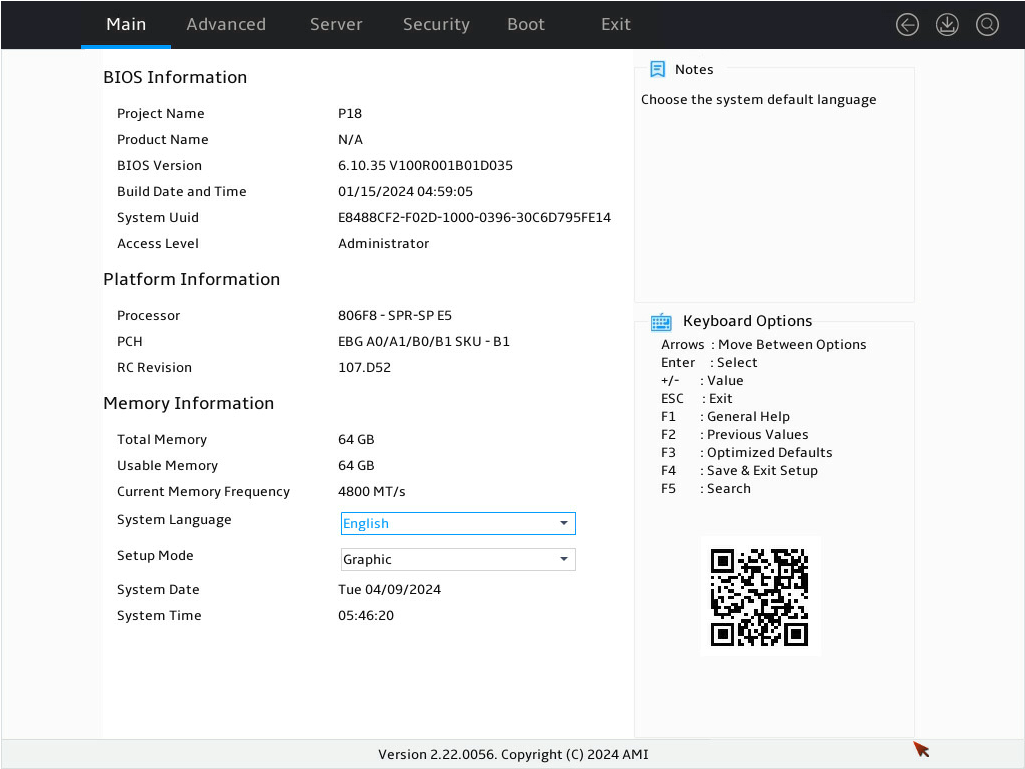
1. Access the BIOS. Press Delete, Esc, or F2 as prompted during server POST to open the BIOS setup screen as shown in Figure 1. For some devices, the Front Page screen opens, and you must select Device Management before proceeding to the next step.
For how to navigate screens and modify settings, see the operation instructions at the lower right corner. In the BIOS GUI, you can move and click the mouse to select and configure features.
Figure 1 BIOS setup screen
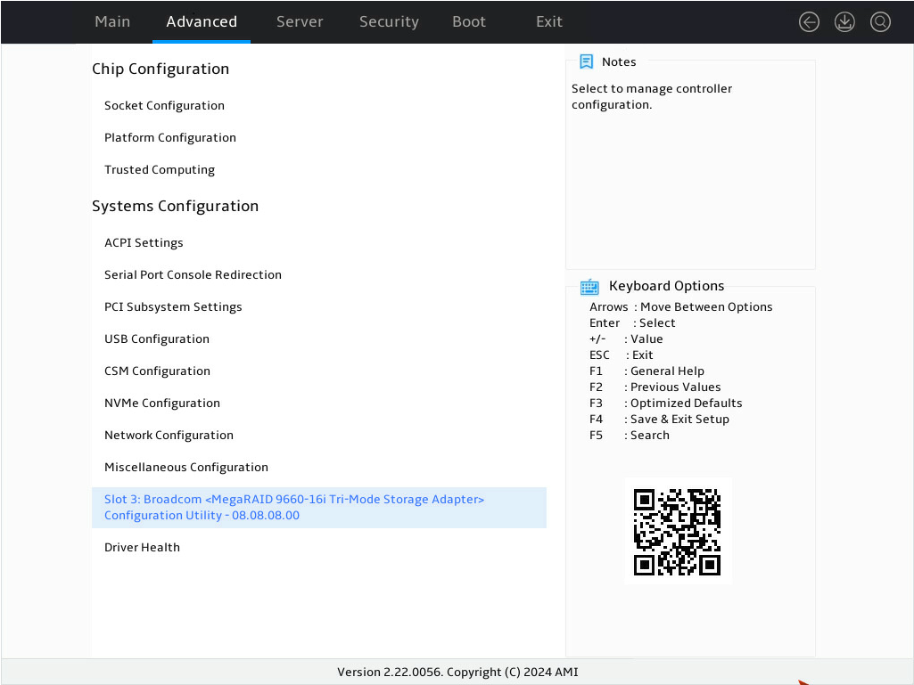
2. Enter the controller management screen.
a. On the top navigation bar, click Advanced.
b. Select the target storage controller, and then press Enter. In this example, the storage controller model is BROADCOM < MegaRAID 9560-8i 4GB 9660-16i Tri-Mode Storage Adapter> Configuration Utility-08.08.08.00.
Figure 2 Advanced screen
3. Select Main Menu as shown in Figure 3, and press Enter.
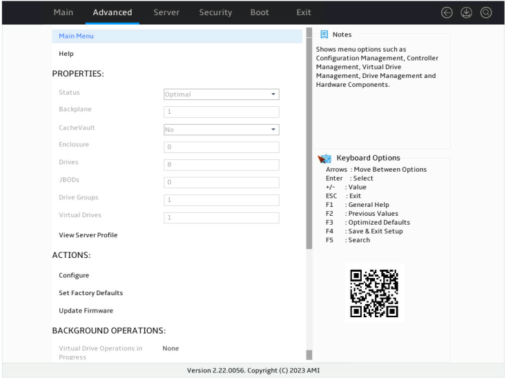
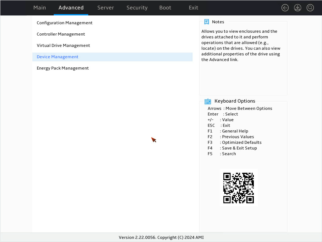
The storage controller configuration screen as shown in Figure 4 opens. This screen contains five tasks as described in Table 3.
Figure 4 Storage controller configuration screen

Table 2 Storage controller configuration tasks
|
Option |
Description |
|
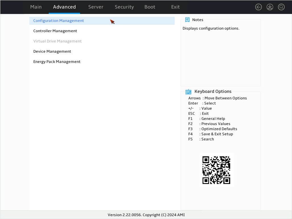
Configuration Management |
Select Configuration Management to perform the following tasks: · Create RAID arrays. · View RAID array properties. · View hot spare drives. · Clear configuration. |
|
Controller Management |
Select Controller Management to perform the following tasks: · View and manage controller properties. · Clear, schedule, or run controller events. |
|
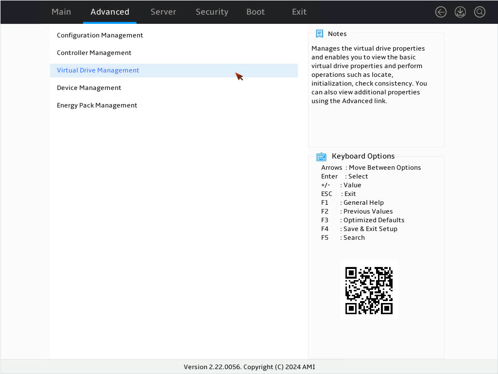
Virtual Drive Management |
Select Virtual Drive Management to perform the following tasks: · View logical drive properties. · Locate logical drives. · Run consistency check. |
|
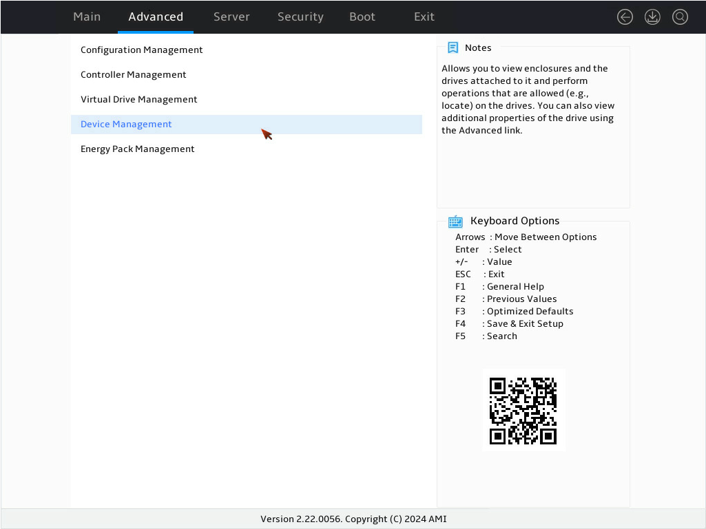
Device Management |
Select Drive Management to perform the following tasks: · View backplane information. · View information about physical drives connected to the backplane. · View physical drive properties. · Perform operations on physical drives, including: ¡ Locate drives. ¡ Initialize drives. ¡ Switch physical drive status. |
|
Energy Pack Management |
Select Energy Pack Management to view supercapacitor properties. |
Switching the drive state
The storage controller supports the following drive states:
· Unconfigured Good—The drive is normal and can be used for RAID array or hot backup configuration.
· Dedicated Hot Spare—The drive is a dedicated hot spare drive.
· Global Hot Spare—The drive is a global hot spare drive.
· JBOD—The drive is a passthrough or passthrough-like drive and does not support RAID configuration.
To switch from Unconfigured Good state to JBOD state as an example:
1. On the storage controller configuration screen as shown in Figure 5, select Device Management and press Enter.
Figure 5 Storage controller configuration screen
2. On the screen as shown in Figure 6, select Logical Enclosure - and press Enter.
Figure 6 Device Management screen

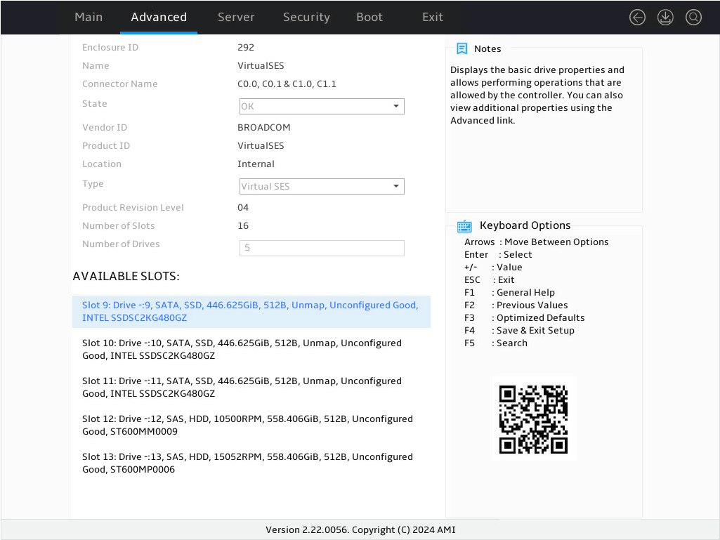
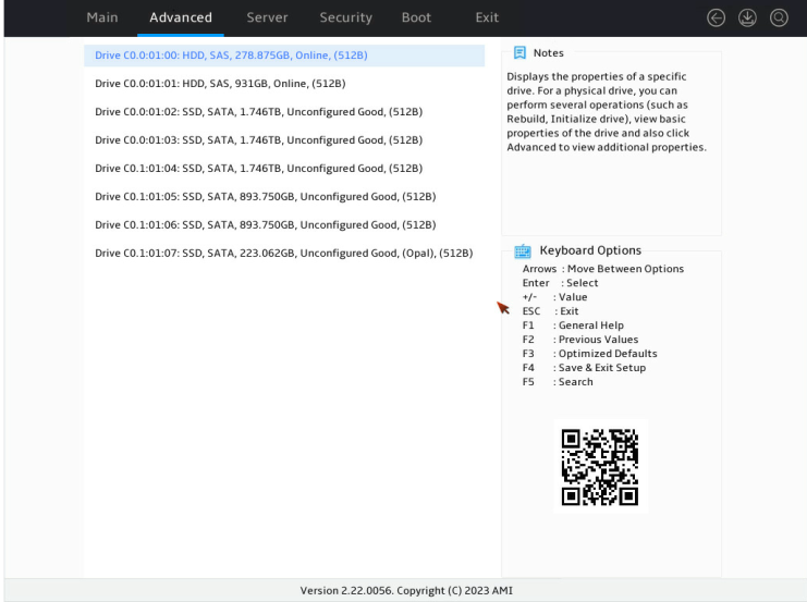
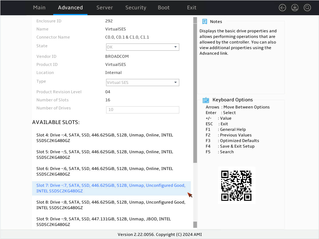
3. On the screen as shown in Figure 7, select the target drive and press Enter.
Figure 7 Selecting the target drive
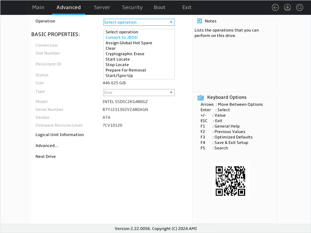
4. On the screen as shown in Figure 8, select Operation and press Enter. In the dialog box that opens, select Convert to JBOD and press Enter.
5. On the screen as shown in Figure 9, select Go and press Enter.

6. On the screen as shown in Figure 10, select OK and press Enter.
Figure 10 Completing drive state switchover

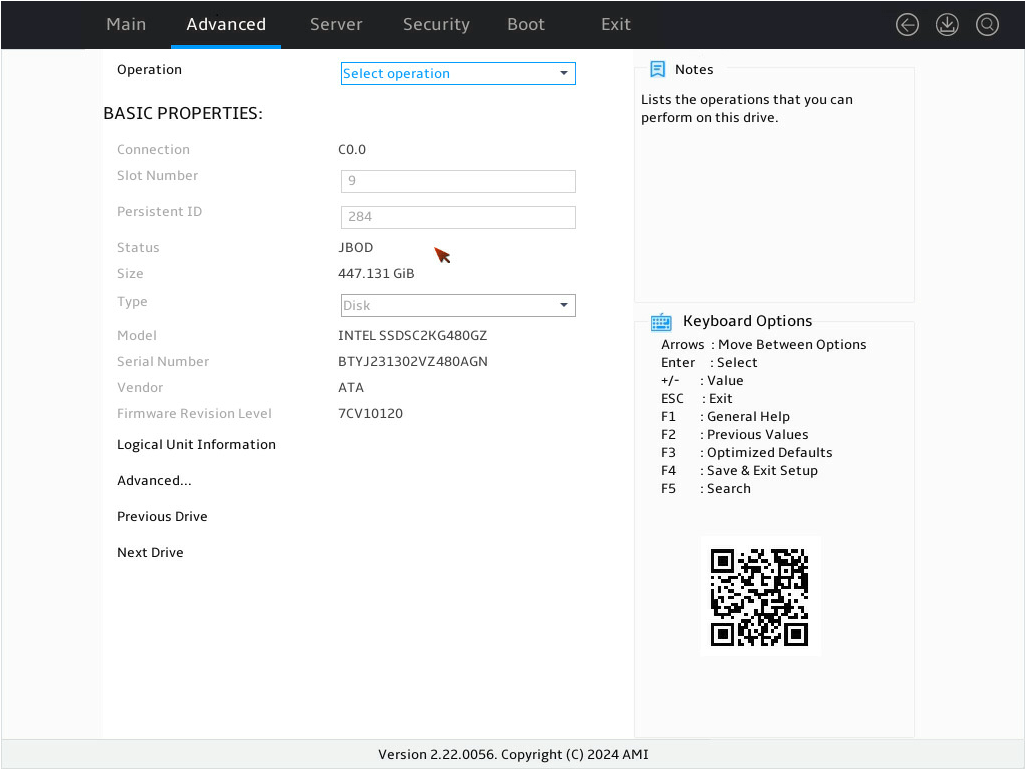
7. On the screen as shown in Figure 11, verify that the status of the target drive is JBOD.
Figure 11 Verifying the drive status under BASIC PROPERTIES for the target drive
Configuring RAID 0/1/5/6/10
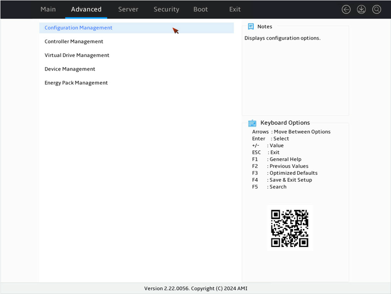
1. On the storage controller configuration screen as shown in Figure 12, select Configuration Management and press Enter.
Figure 12 Storage controller configuration screen

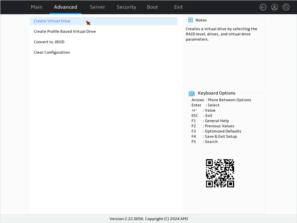
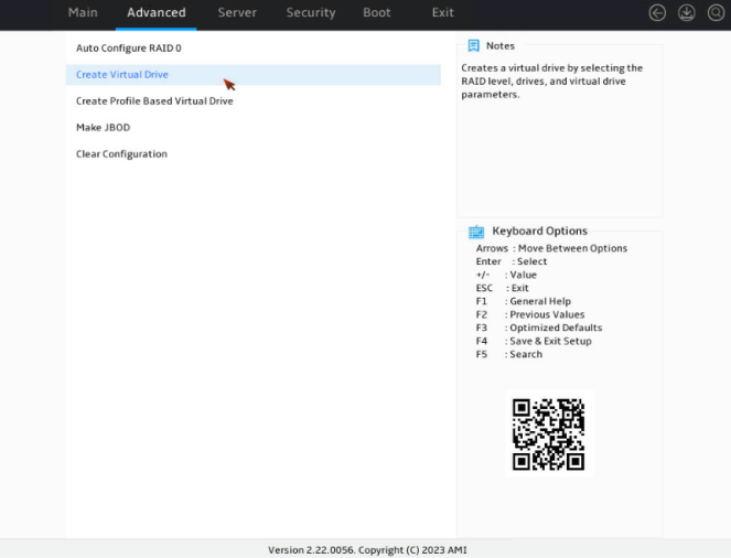
2. On the screen as shown in Figure 13, select Create Virtual Drive and press Enter.
Figure 13 Selecting Create Virtual Drive
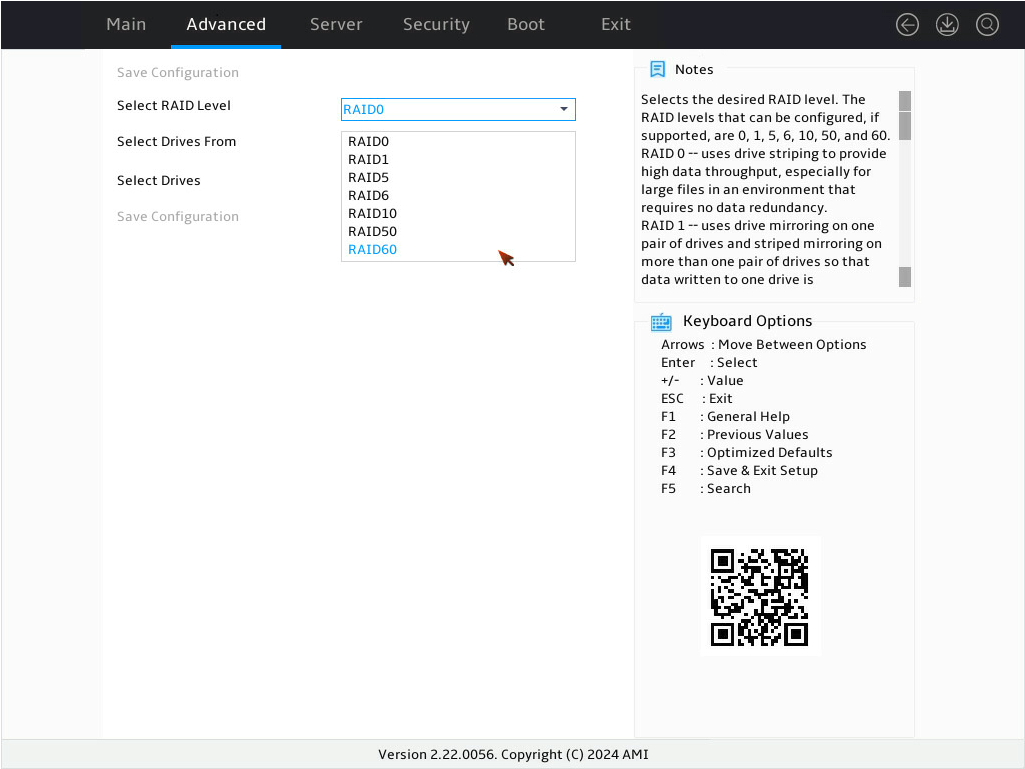
3. On the screen as shown in Figure 14, select Select RAID Level to set the RAID level, for example RAID 0, and then press Enter.
Figure 14 Setting the RAID level

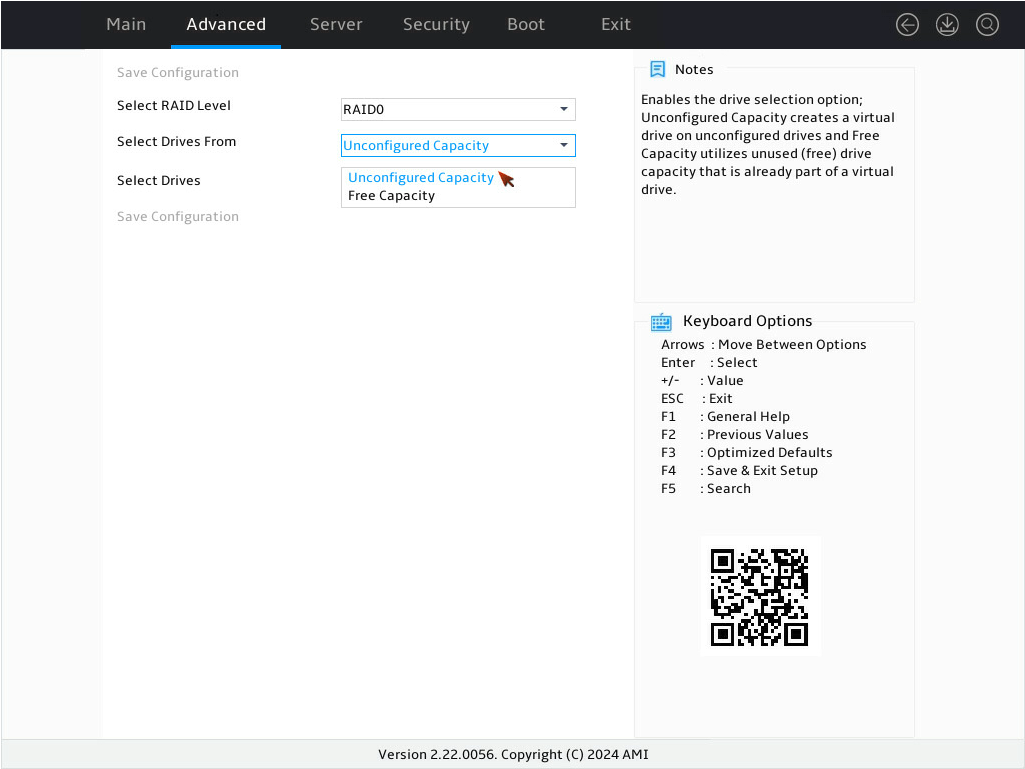
4. On the screen as shown in Figure 15, select Select Drives From to set the drive capacity source, and then press Enter.
¡ Unconfigured Capacity—The capacity source is the unconfigured drives. This example selects Unconfigured Capacity as an example.
¡ Free Capacity—The capacity source is the remaining drive capacity of the drives that have been used for RAID setup.
Figure 15 Setting the drive capacity source
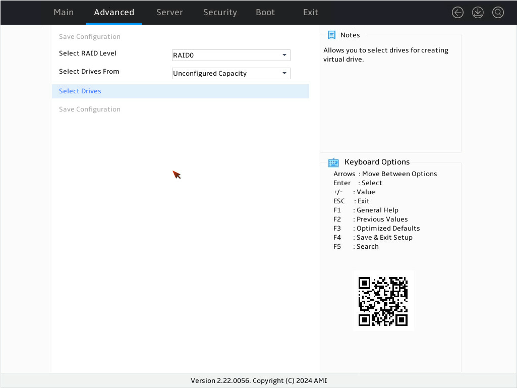
5. On the screen as shown in Figure 16, select Select Drives and press Enter.
Figure 16 Selecting Select Drives
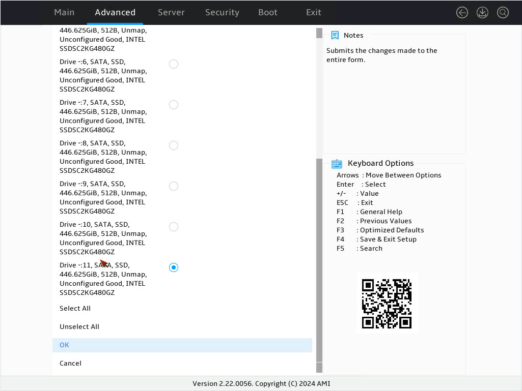
6. On the screen as shown in Figure 17, select the target drives and press Enter. Then, select OK and press Enter. A drive in JBOD, Unconfigured Bad, or Hotspare status cannot be selected for RAID configuration.
Figure 17 Selecting the target drives
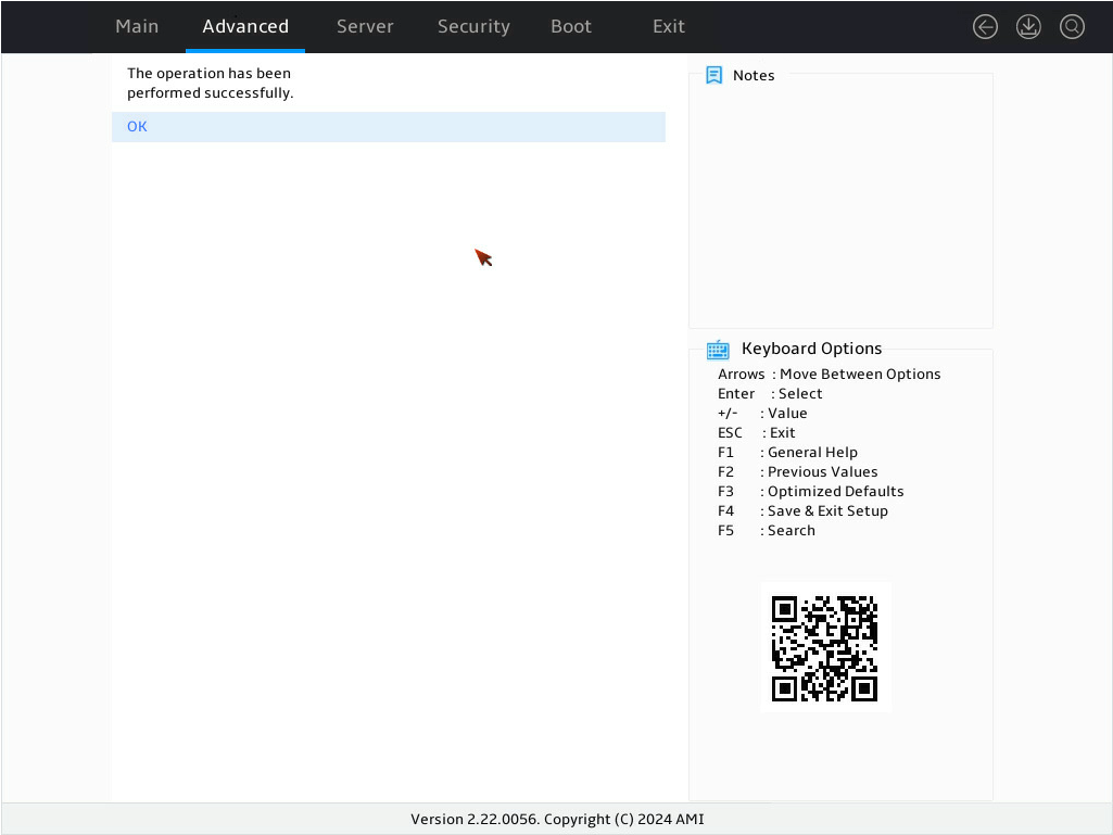
7. On the screen as shown in Figure 18, select OK and press Enter.
Figure 18 Completing selecting drives
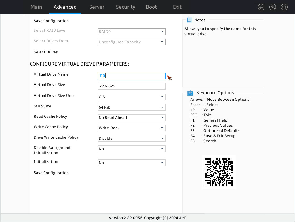
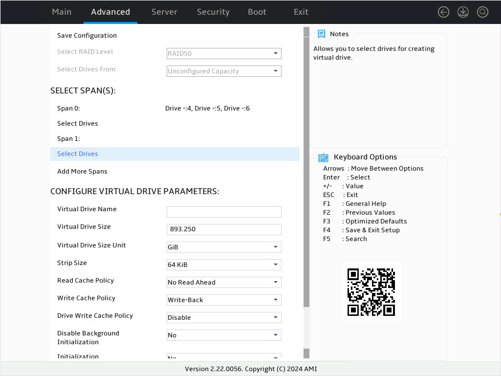
8. On the screen as shown in Figure 19, configure the parameters, select Save Configuration, and press Enter. For more information about the parameter description, see Table 4.
Figure 19 Configuring RAID parameters
|
Parameter |
Description |
|
Virtual Drive Name |
RAID array name, a case-insensitive string of letters, digits, and special characters. |
|
Virtual Drive Size |
Capacity for the RAID array. |
|
Virtual Drive Size Unit |
Capacity unit for the RAID array. |
|
Strip Size |
Strip size of the RAID array, that is, data block size for each drive. For logical drives of SSDs, a strip size of 64 KiB is supported. For logical drives of HDDs, the supported strip sizes are 64 KiB and 256 KiB. |
|
Read Cache Policy |
Read cache policy: · Read Ahead—Enables read ahead capability. When this capability is enabled, the storage controller can pre-read sequential data or anticipate data to be requested and store the data in the cache · No Read Ahead—Disables read ahead capability. NOTE: a The read ahead feature is available only for logical drives of HDDs that are configured in Write Back mode. This feature is not available for logical drives of SSDs. It does not take effect even when you set the SSD-based logical drive to Read Ahead and the cache policy will display No Read Ahead. b The read ahead feature will be disabled during recovery processes at the back end, including rebuilding, copyback, and online scale-up of logical drives.. c When the supercapacitor is damaged, logical drives in Write Back mode will switch to Write Through mode, and the read ahead feature will be disabled. |
|
Write Cache Policy |
Write cache policy: · Write through—Enables the controller to send data transfer completion signal to the host when the physical drives have received all data in a transaction. · Write back—Enables the controller to send data transfer completion signal to the host when the controller cache receives all data in a transaction. If the supercapacitor is faulty or no supercapacitor is present, the write cache policy will automatically switch to Write through mode. · Always write back—Uses the Write back policy forcedly. Even if the supercapacitor of the storage controller is absent or faulty, it will not switch to Write through mode. If the server is powered off, the controller cache loses its data because of lack of power. As a best practice, select this option with caution. |
|
Drive Write Cache Policy |
Drive cache policy: · Enable—Enables the drive cahe policy. In this case, data is written to the cache through the drive during the write process, which improves write performance. However, data might get lost upon an unexpected power failure if additional protection mechanism is not in place. · Disable—Disables the drive cache policy. In this case, data is written to the cache without passing through the drive during the write process. Data will not get lost upon an unexpected power failure. · Default—Maintains the current drive cache policy. |
|
Disable Background Initialization |
Enabling status of background initialization. |
|
Initialization |
Default initialization mode: · No. · Fast. · Full. |
|
Save Configuration |
Select this option to save the configuration. |
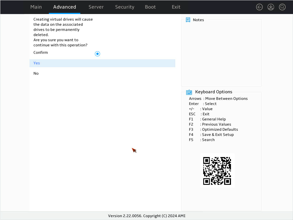
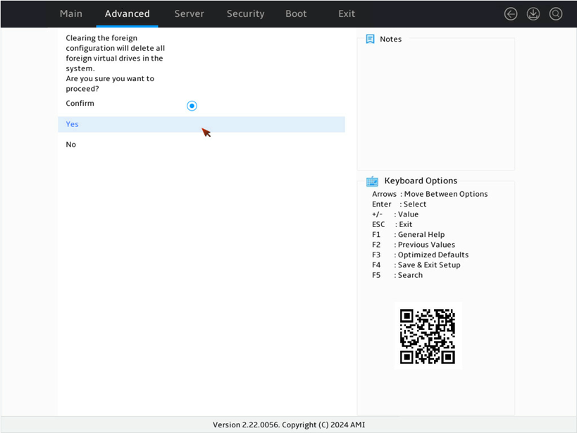
9. On the screen as shown in Figure 20, select Confirm and press Enter. ([Enabled] following the drive means that the drive has been selected.) Then, select Yes and press Enter.
Figure 20 Confirming the operation
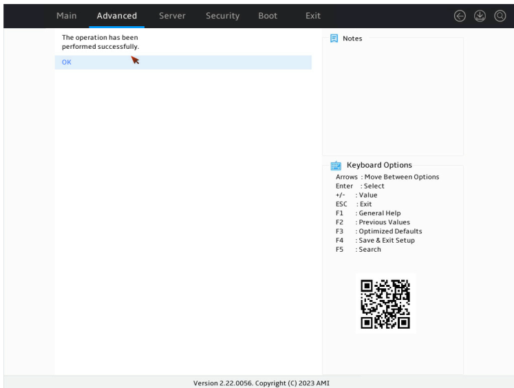
10. On the screen as shown in Figure 21, select OK and press Enter to return to the storage controller configuration screen.
Figure 21 Completing RAID array configuration successfully

11. Select Virtual Drive Management and press Enter as shown in Figure 22.
Figure 22 Storage controller configuration screen
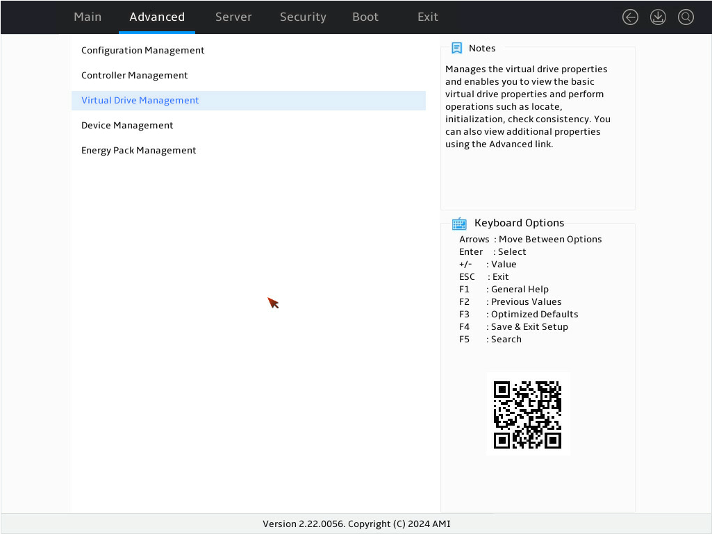
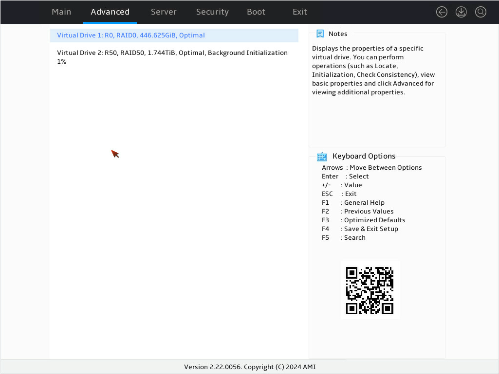
12. On the screen as shown in Figure 23, you can see the created drives. Select the drive you want to view and press Enter.
Figure 23 Virtual Drive Management screen

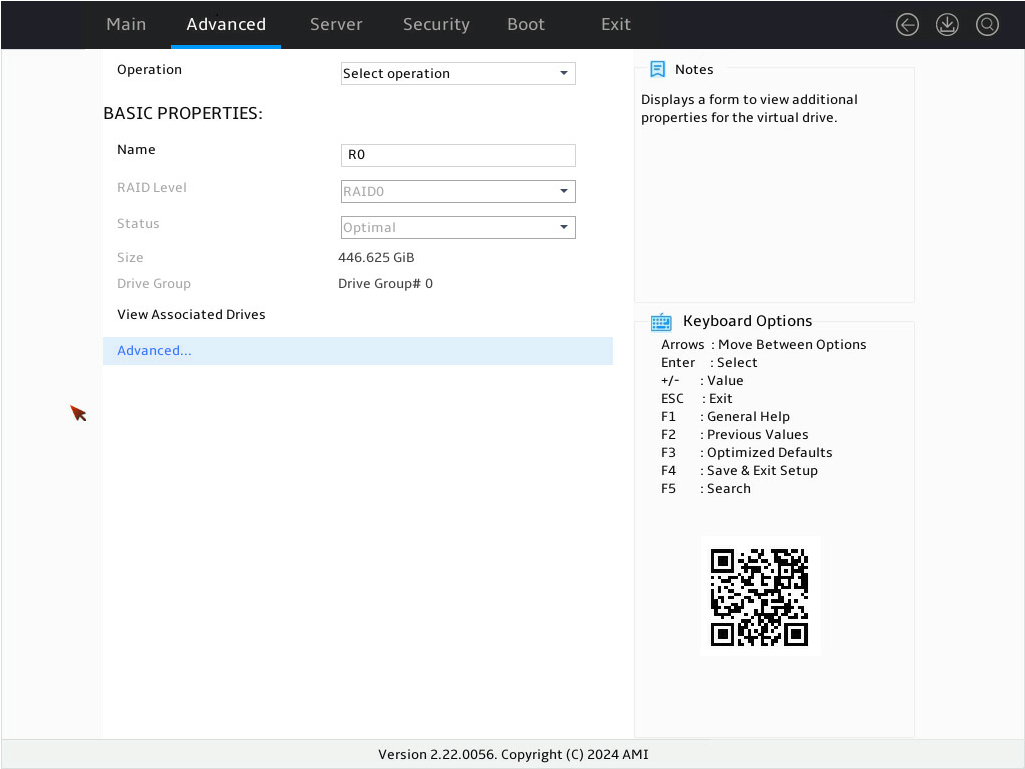
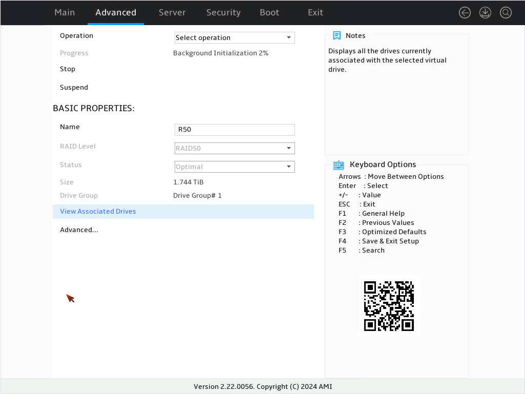
13. On the screen as shown in Figure 24, select View Associated Drives and press Enter. You can view the detailed information about the member drives of the RAID.
Figure 24 Selecting View Associated Drives

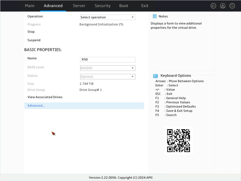
14. On the screen as shown in Figure 25, select Advanced…, and then press Enter. You can view the detailed information about the RAID array, including strip, Write Cache Policy, and Read Cache Policy.
Figure 25 Selecting Advanced…
Configuring RAID 50
1. On the storage controller configuration screen as shown in Figure 26, select Configuration Management and press Enter.
Figure 26 Storage controller configuration screen
2. On the screen as shown in Figure 27, select Create Virtual Drive and press Enter.
Figure 27 Selecting Create Virtual Drive

3. On the screen as shown in Figure 28, select Select RAID Level to set the RAID level, and then press Enter.
Figure 28 Setting the RAID level

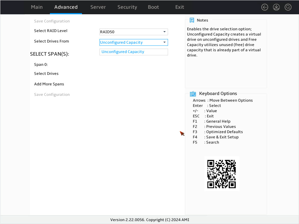
4. On the screen as shown in Figure 29, select Select Drives From to set the drive capacity source, and then press Enter.
¡ Unconfigured Capacity—The capacity source is the unconfigured drives. This example selects Unconfigured Capacity as an example.
¡ Free Capacity—The capacity source is the remaining drive capacity of the drives that have been used for RAID setup.
Figure 29 Setting the drive capacity source
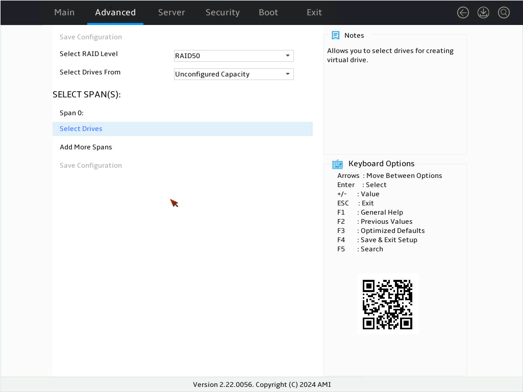
5. On the screen as shown in Figure 30, select Select Drives under Span 0: and press Enter.
6. Select Select Drives.
Figure 30 Selecting Select Drives
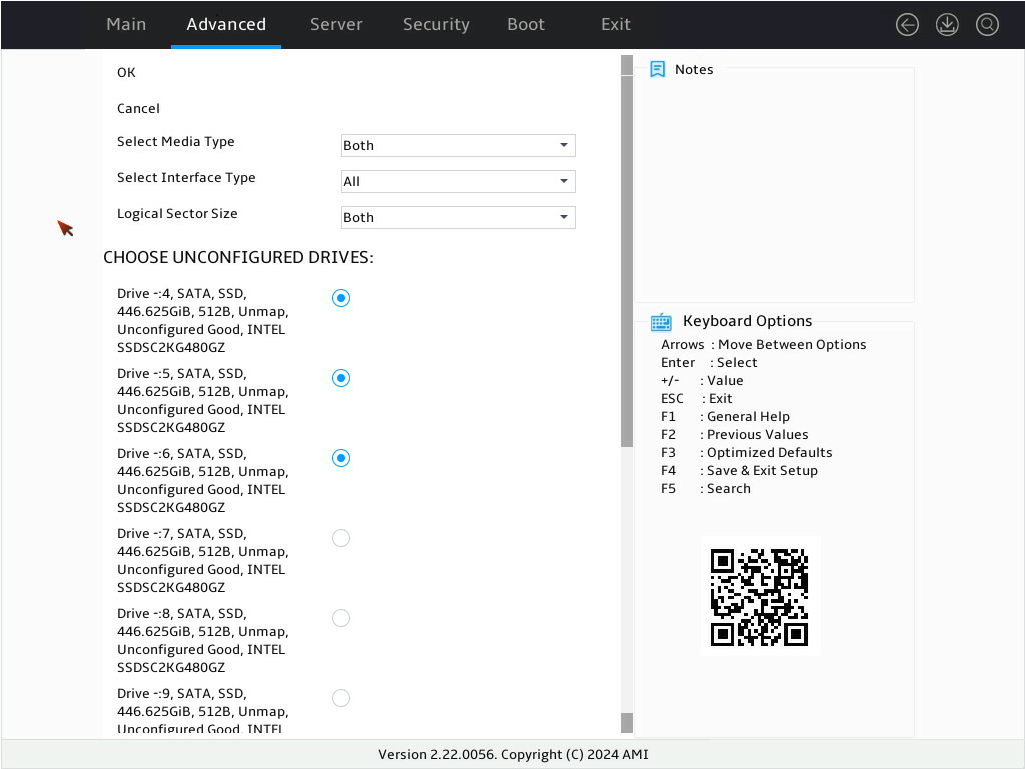
7. On the screen as shown in Figure 31, select the target drives, press Enter. Then, select OK and press Enter.
Figure 31 Selecting the target drives
8. On the screen as shown in Figure 32, select OK and press Enter.
Figure 32 Completing target drive selection

9. On the screen as shown in Figure 33, select Add More Spans and press Enter to add Span1:.
Figure 33 Selecting Add More Spans

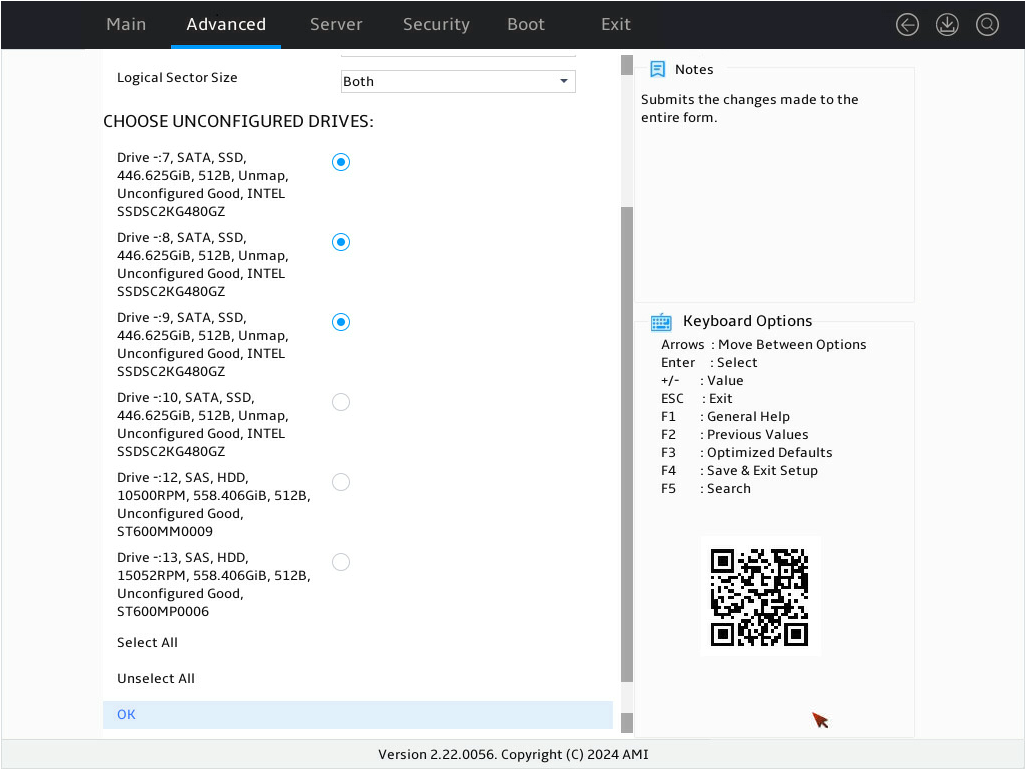
10. On the screen as shown in Figure 34, select Select Drives under Span 1: and press Enter.
Figure 34 Selecting Select Drives
11. On the screen as shown in Figure 35, select the target drives for RAID setup and press Enter. Make sure the number of the selected drive is the same as that in step 7. Then, select OK and press Enter.
Figure 35 Selecting the target drives
12. On the screen as shown in Figure 36, select OK and press Enter.
Figure 36 Completing target drive selection

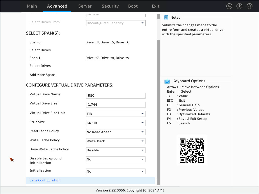
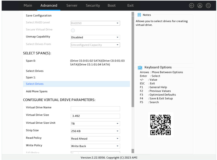
13. On the screen as shown in Figure 37, configure the parameters, select Save Configuration, and press Enter. For more information about the parameter description, see Table 4.
Figure 37 Configuring RAID parameters
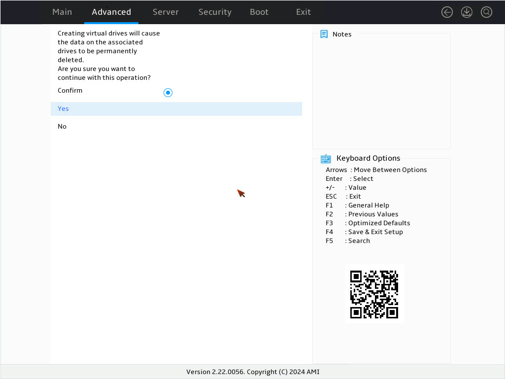
14. On the screen as shown in Figure 38, select Confirm and press Enter. ([Enabled] following the drive means that the drive has been selected.) Then, select Yes and press Enter.
Figure 38 Confirming the operation
15. On the screen as shown in Figure 39, select OK and press Enter to return to the storage controller configuration screen.
Figure 39 Completing RAID array configuration successfully

16. As shown in Figure 40, on the storage controller configuration screen, select Virtual Drive Management and press Enter.
Figure 40 Storage controller configuration screen
17. On the screen as shown in Figure 41, you can see the created RAID arrays. Select RAID50 you want to view and press Enter.
Figure 41 Virtual Drive Management screen
18. On the screen as shown in Figure 42, select View Associated Drives and press Enter. You can view the detailed information about the member drives of the RAID.
Figure 42 Selecting View Associated Drives
19. On the screen as shown in Figure 43, select Advanced… and press Enter. You can view the detailed information about the RAID array, including stripe, Write Cache Policy and Read Cache Policy.
Figure 43 Selecting Advanced…
Configuring RAID 60
1. On the storage controller configuration screen as shown in Figure 44, select Configuration Management and press Enter.
Figure 44 Storage controller configuration screen

2. On the screen as shown in Figure 45, select Create Virtual Drive and press Enter.
Figure 45 Selecting Create Virtual Drive

3. On the screen as shown in Figure 46, select Select RAID Level to set the RAID level, and then press Enter.
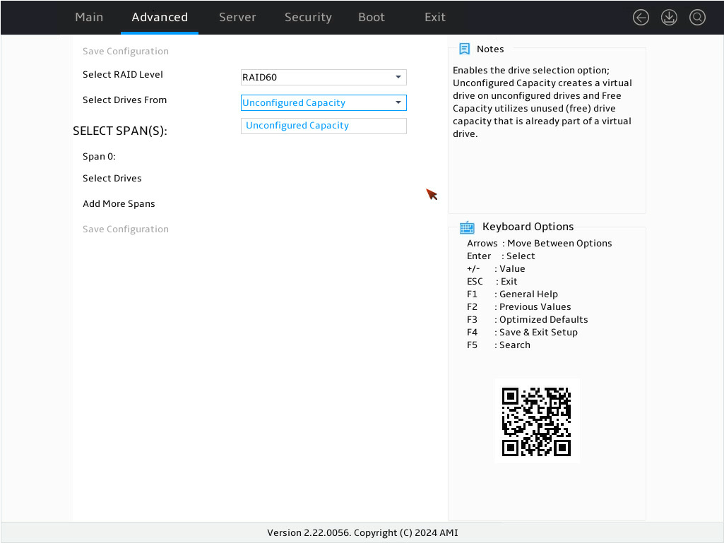
4. On the screen as shown in Figure 47, select Select Drives From to set the drive capacity source, and then press Enter.
¡ Unconfigured Capacity—The capacity source is the unconfigured drives. This example selects Unconfigured Capacity as an example.
¡ Free Capacity—The capacity source is the remaining drive capacity of the drives that have been used for RAID setup.
Figure 47 Setting the drive capacity source
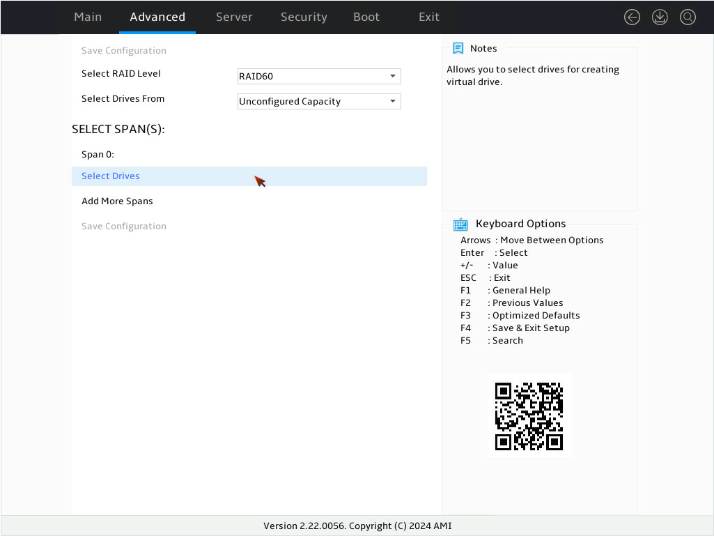
5. On the screen as shown in Figure 48, select Select Drives under Span 0: and press Enter.
Figure 48 Selecting Select Drives
6. On the screen as shown in Figure 49, select the target drives, press Enter. Then, select OK and press Enter.
Figure 49 Selecting the target drives

7. On the screen as shown in Figure 50, select OK and press Enter.
Figure 50 Completing target drive selection

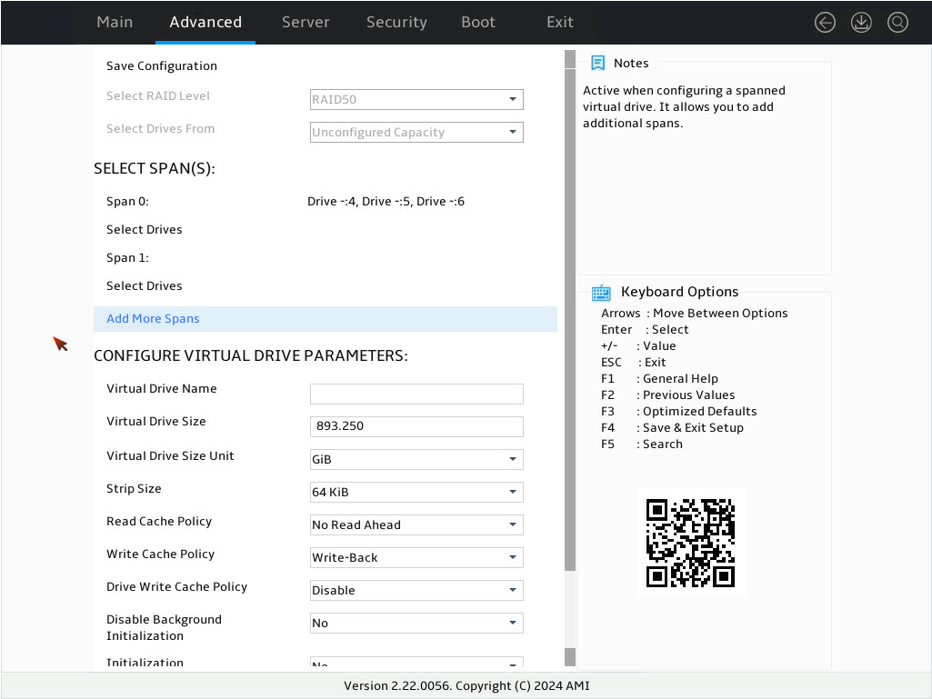
8. On the screen as shown in Figure 51, select Add More Spans and press Enter to add Span1:.
Figure 51 Selecting Add More Spans
9. On the screen as shown in Figure 52, select Select Drives under Span 1: and press Enter.
Figure 52 Selecting Select Drives
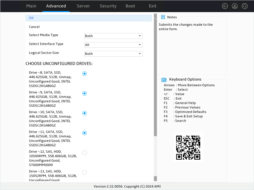
10. On the screen as shown in Figure 53, select the target drives and press Enter. Make sure the number of selected drive matches step 6. Then, select OK and press Enter.
Figure 53 Selecting the target drives
11. On the screen as shown in Figure 32, select OK and press Enter.
Figure 54 Completing target drive selection

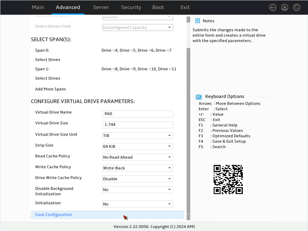
12. On the screen as shown in Figure 55, configure the parameters, select Save Configuration, and press Enter. For more information about the parameter description, see Table 4.
Figure 55 Configuring RAID parameters
13. On the screen as shown in Figure 56, select Confirm and press Enter. ([Enabled] following the drive means that the drive has been selected.) Then, select Yes and press Enter.
Figure 56 Confirming the operation

14. On the screen as shown in Figure 57, select OK and press Enter to return to the storage controller configuration screen.
Figure 57 Completing RAID array configuration

15. On the storage controller configuration screen as shown in Figure 58, select Virtual Drive Management and press Enter.
Figure 58 Storage controller configuration screen

16. On the screen as shown in Figure 59, you can see the created RAID arrays. Select RAID 60 you want to view and press Enter.
Figure 59 Virtual Drive Management screen

17. On the screen as shown in Figure 60, select View Associated Drives and press Enter. You can view the detailed information about the member drives of the RAID.
Figure 60 Selecting View Associated Drives

18. On the screen as shown in Figure 61, select Advanced… and press Enter. You can view the detailed information about the RAID array, including strip, Write Cache Policy and Read Cache Policy.
Figure 61 Selecting Advanced…

Configuring hot spare drives
For data security purposes, configure hot spare drives after configuring a RAID array. You can configure global hot spare drives or dedicated hot spare drives.
|
|
NOTE: · A hot spare drive can be used only for RAID levels with redundancy. · The capacity of a hot spare drive must be equal to or greater than the capacity of the smallest drive in the RAID array. · Only the drive in Unconfigured Good state can be configured as a hot spare drive. |
Configuring a global hot spare drive
1. On the storage controller configuration screen as shown in Figure 62, select Device Management and press Enter.
Figure 62 Storage controller configuration screen
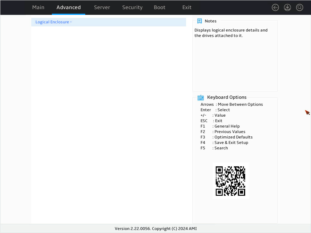
2. On the screen as shown in Figure 3, select Logical Enclosure - and press Enter.
Figure 63 Device Management screen

3. On the screen as shown in Figure 4, select the target drive and press Enter.
Figure 64 Selecting the target drive

4. On the screen as shown in Figure 5, select Operation and press Enter. In the dialog box that opens, select Assign Global Hot Spare Drive and press Enter.

5. On the screen as shown in Figure 6, select Go and press Enter.

6. On the screen as shown in Figure 7, select OK and press Enter.
Figure 67 Completing global hot spare drive configuration

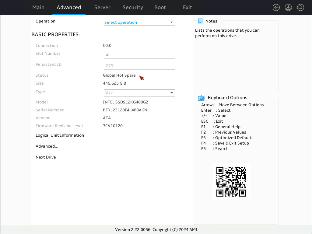
7. On the screen as shown in Figure 8, verify that the state of the target drive is Global Hot Spare.
Figure 68 Verifying the drive status under BASIC PROPERTIES for the target drive
Configuring a dedicated hot spare drive
1. On the storage controller configuration screen as shown in Figure 9, select Device Management and press Enter.
Figure 69 Storage controller configuration screen

2. On the screen as shown in Figure 10, select Logical Enclosure - and press Enter.
Figure 70 Device Management screen
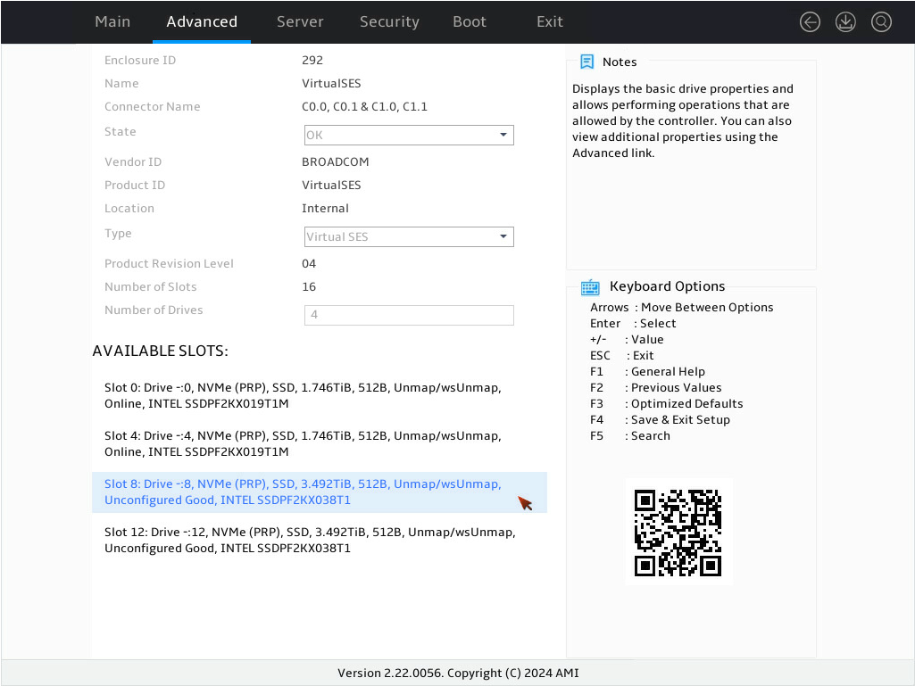
3. On the screen as shown in Figure 11, select the dedicated global hot spare drive and press Enter.
Figure 71 Selecting the target drive
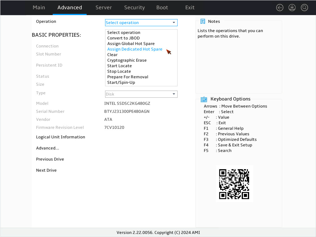
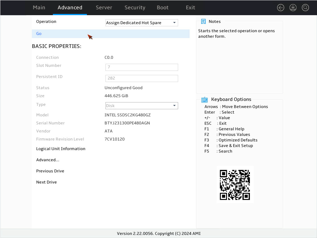
4. On the screen as shown in Figure 12, select Operation and press Enter. In the dialog box that opens, select Assign Dedicated Hot Spare Drive and press Enter.
5. On the screen as shown in Figure 13, select Go and press Enter.
6. On the screen as shown in Figure 14, select the drive you want to configure as the hot spare drive. ([Enabled] following the drive means that the drive has been selected.) Then, select OK and press Enter.
Figure 74 Confirming selection

7. On the screen as shown in Figure 15, complete the dedicated hot spare drive configuration. Then, select OK and press Enter.
Figure 75 Completing dedicated hot spare drive configuration

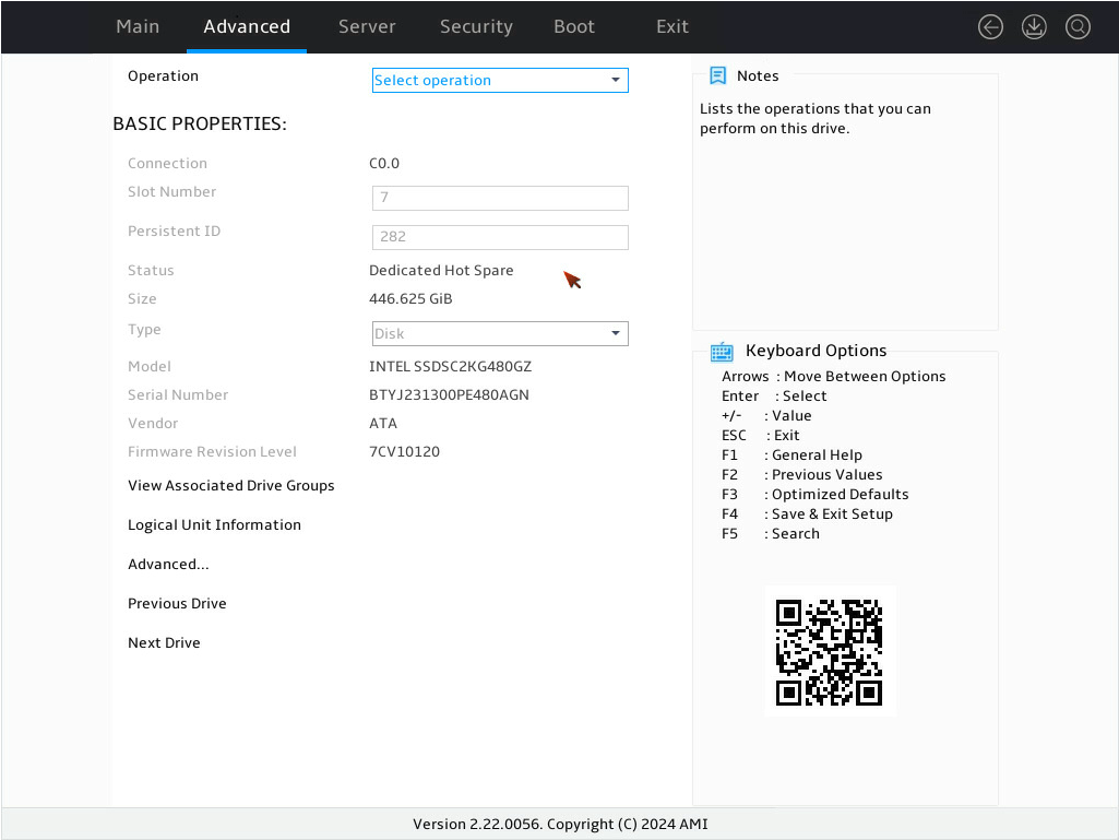
8. On the screen as shown in Figure 16, ensure the target drive shows Dedicated Hot Spare to complete the dedicated hot spare drive configuration.
Figure 76 Verifying the drive status under BASIC PROPERTIES for the target drive
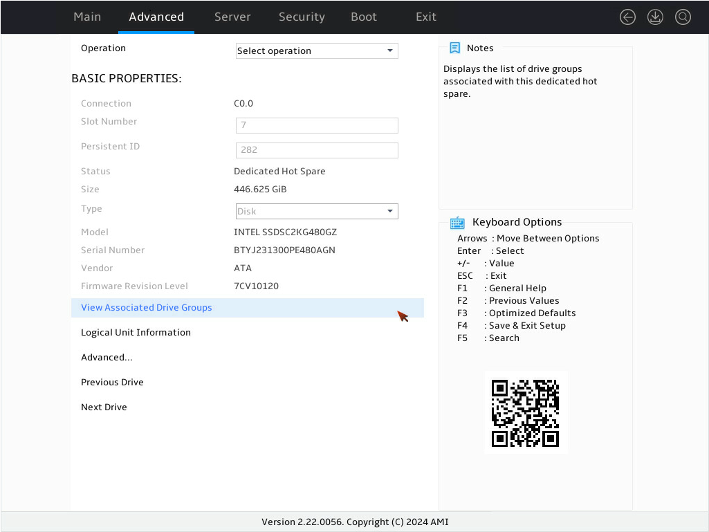
9. On the screen as shown in Figure 17 select View Associated Drive Groups and press Enter to view the logical drive group for the dedicated hot spare drive.
Figure 77 Selecting View Associated Drive Groups
Deleting a RAID array
1. On the storage controller configuration screen as shown in Figure 18, select Virtual Drive Management and press Enter.
Figure 78 Storage controller configuration screen

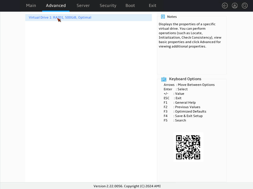
2. On the screen as shown in Figure 3, select the target virtual drive and press Enter.
Figure 79 Virtual Drive Management screen

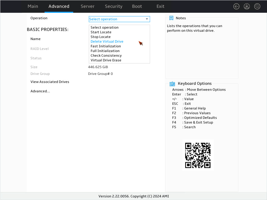
3. On the screen as shown in Figure 4, select Operation and press Enter. In the dialog box that opens, select Delete Virtual Drive and press Enter.
4. On the screen as shown in Figure 5, select Go and press Enter.

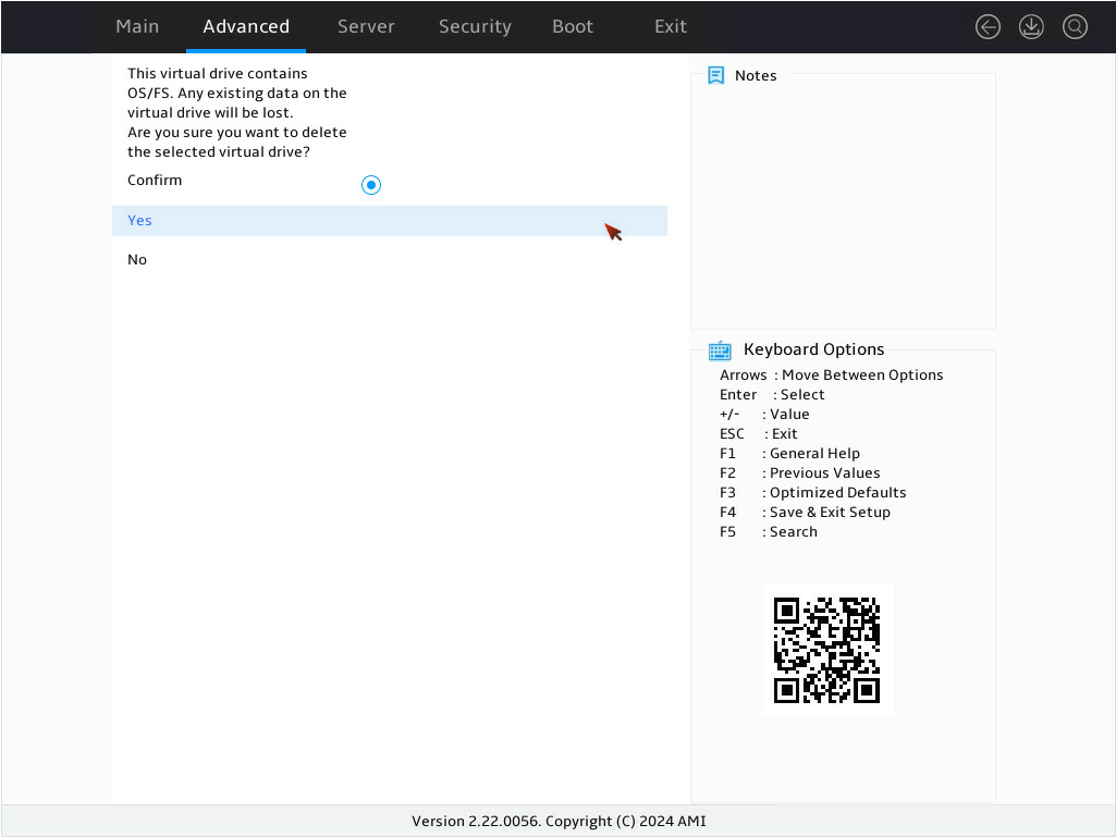
5. On the screen as shown in Figure 6, select Confirm and press Enter. ([Enabled] following the drive means that the drive has been confirmed.) Then, select Yes and press Enter.
Figure 82 Confirming the deletion
6. On the screen as shown in Figure 7, select OK and press Enter, the operation is complete.
Figure 83 Completing the operation

Locating drives
This task allows you to locate a physical drive or all drives for a virtual drive.
Locating a physical drive
1. On the storage controller configuration screen as shown in Figure 8, select Device Management and press Enter.
Figure 84 Storage controller configuration screen

2. On the screen as shown in Figure 9, select Logical Enclosure - and press Enter.
Figure 85 Device Management screen

3. On the screen as shown in Figure 10, select the target drive and press Enter.
Figure 86 Selecting the target drive

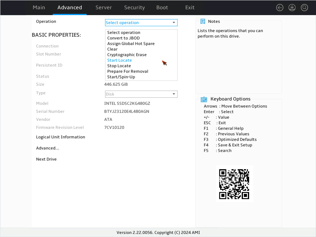
4. On the screen as shown in Figure 11, select Operation and press Enter. In the dialog box that opens, select Start Locate and press Enter.
Figure 87 Selecting Start Locate in Operation screen
5. On the screen as shown in Figure 12, select Go and press Enter.
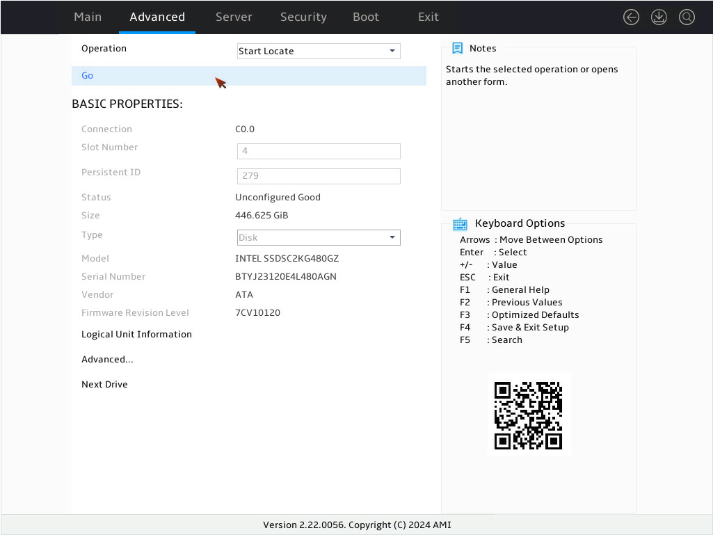
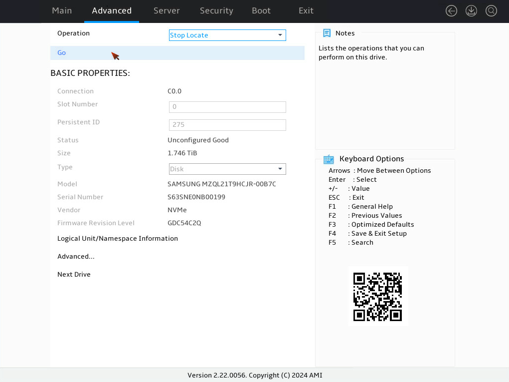
6. On the screen as shown in Figure 13, select OK and press Enter to the physical drive properties interface.
Figure 89 Completing locating the physical drive

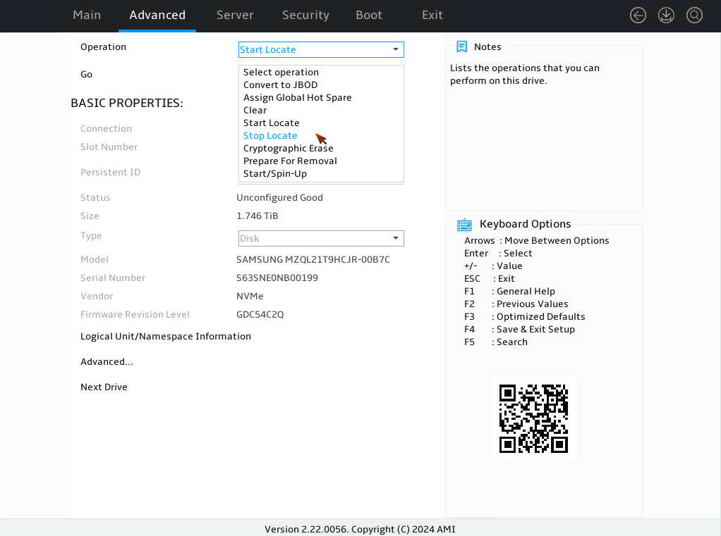
7. On the screen as shown in Figure 14, to stop locating the target physical drive, select Operation and press Enter. In the dialog box that opens, select Stop Locate and press Enter.
Figure 90 Selecting Stop Locate
8. On the screen as shown in Figure 15, select Go and press Enter.
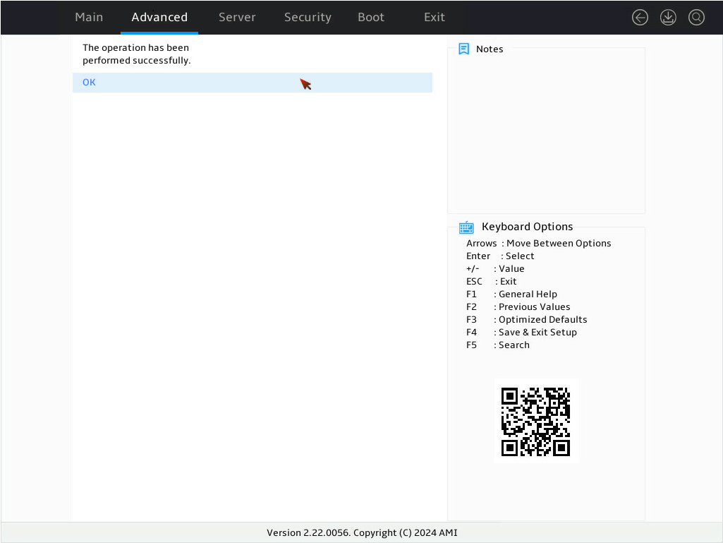
9. On the screen as shown in Figure 16, select OK and press Enter to the physical drive properties interface.

Locating all drives for a virtual drive
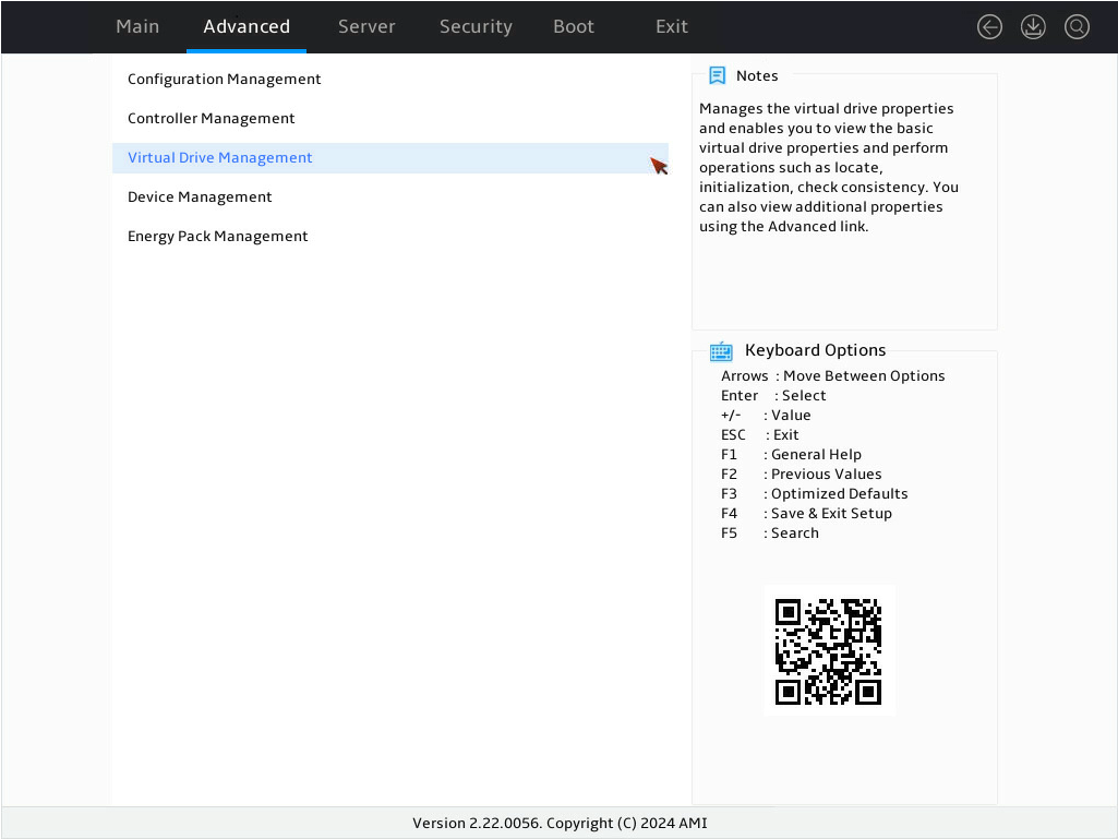
1. On the storage controller configuration screen as shown in Figure 17, select Virtual Drive Management and press Enter.
Figure 93 Storage controller configuration screen

2. On the screen as shown in Figure 18, select the target drive and press Enter.
Figure 94 Selecting the target drive

3. On the screen as shown in Figure 19, select Operation and press Enter. In the dialog box that opens, select Start Locate and press Enter.

4. On the screen as shown in Figure 20, select Go and press Enter.

5. On the screen as shown in Figure 21, select OK and press Enter to the physical drive properties interface.
Figure 97 Completing locating all drives for a virtual drive
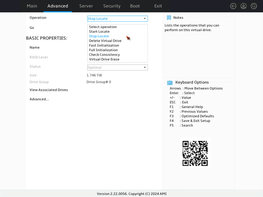
6. On the screen as shown in Figure 22, to stop locating all drives for a virtual drive, select Operation and press Enter. In the dialog box that opens, select Stop Locate and press Enter.
Figure 98 Selecting Stop Locate
7. On the screen as shown in Figure 23, select Go and press Enter.

8. On the screen as shown in Figure 24, select OK and press Enter to the logical drive properties interface.

Initializing a virtual drive
This task allows you to initialize a virtual drive to be used by operating systems.
To initialize a virtual drive:
1. On the storage controller configuration screen as shown in Figure 25, select Virtual Drive Management and press Enter.
Figure 101 Storage controller configuration screen
2. On the screen as shown in Figure 26, select the target drive and press Enter.
Figure 102 Selecting the target drive

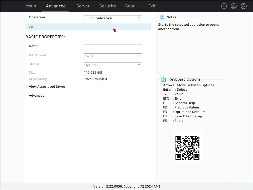
3. On the screen as shown in Figure 27, select Operation and press Enter. In the dialog box that opens, select Fast Initialization or Full Initialization and press Enter. This example selects Full Initialization.

|
|
NOTE: Fast initialization allows immediately writing data. Full initialization allows writing data after initialization is complete. |
4. On the screen as shown in Figure 28, select Go and press Enter.
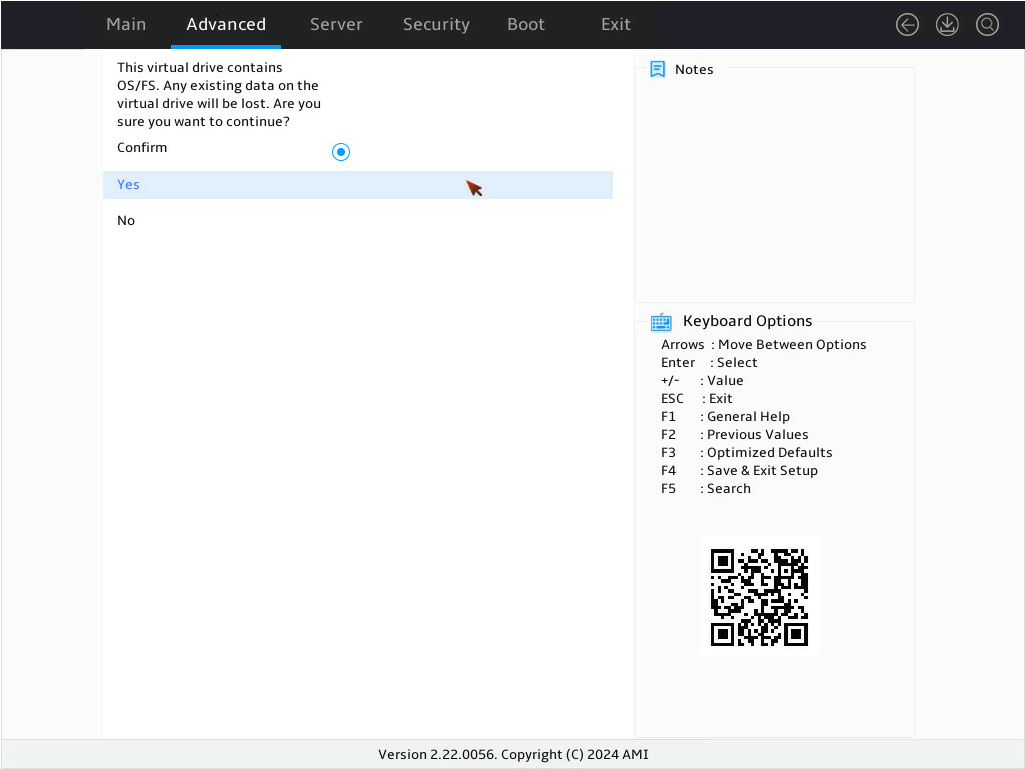
5. On the screen as shown in Figure 29, select Confirm and press Enter. ([Enabled] following the drive means that the drive has been selected.) Then, select Yes and press Enter.
Figure 105 Confirming the initialization
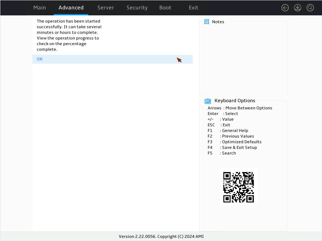
6. On the screen as shown in Figure 30, select OK and press Enter.
Figure 106 Completing the operation
Initializing a physical drive
1. On the storage controller configuration screen as shown in Figure 31, select Device Management and press Enter.
Figure 107 Storage controller configuration screen

2. On the screen as shown in Figure 3, select Logical Enclosure - and press Enter.
Figure 108 Device Management screen
3. On the screen as shown in Figure 4, select the target drive and press Enter.
Figure 109 Selecting the target drive
|
|
NOTE: Only physical drives in the Unconfigured Good state support the initialization operation. |
4. On the screen as shown in Figure 5, select Operation and press Enter. In the dialog box that opens, select Clear and press Enter.
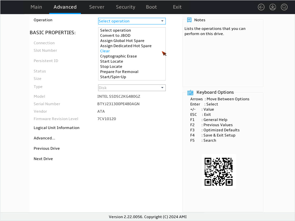
5. On the screen as shown in Figure 6, select Go and press Enter.

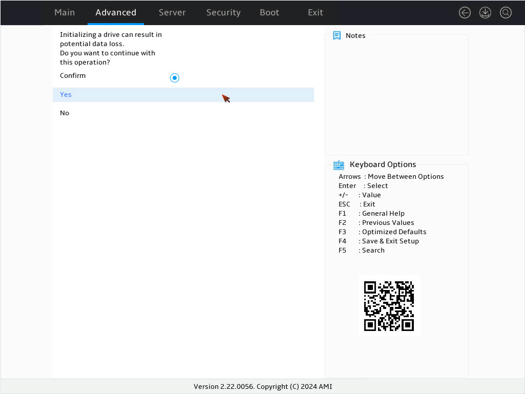
6. On the screen as shown in Figure 7, select Confirm and press Enter. ([Enabled] following the drive means that the drive has been selected.) Then, select Yes and press Enter.
Figure 112 Confirming the initialization
7. On the screen as shown in Figure 8, select OK and press Enter.
Figure 113 Completing the operation

Expanding a RAID array online
Perform this task to expand the logical drive capacity by using unused drive space in the array or adding new physical drives to the array.
Restrictions and guidelines
· Before performing online expansion, back up the data on the logical drive to be expanded as a best practice.
· Do not restart the system during the online expansion.
· Do not remove logical drive members during online expansion. If you fail to do so, data loss might occur.
· When a storage controller is performing online expansion, the logical drive setup feature is disabled.
· Online expansion is not supported in the following scenarios:
¡ The array to which the target logical drive belongs has multiple logical drives.
¡ The target logical drive does not start from the beginning of the array.
¡ The target logical drive is performing initialization, secure erase, consistency check, rollback, or rebuilding.
¡ The storage controller is performing an expansion operation by adding new physical drives.
Using unused drive space in the array
|
|
NOTE: · Drive space expansion by using unused drive space in the array is available only for RAID levels 0, 1, 5, and 6 in UEFI mode or in the OS. · After RAID levels 0, 1, 5, and 6 uses unused drive space for expansion, the background initialization starts immediately. |
This task allows you to expand the RAID array capacity by setting the percentage of available logical drive capacity for availability purposes.
To use unused drive space in the array:
1. On the storage controller configuration screen as shown in Figure 9, select Virtual Drive Management and press Enter.
Figure 114 Storage controller configuration screen

2. On the screen as shown in Figure 3, select the target drive and press Enter.
Figure 115 Virtual Drive Management screen
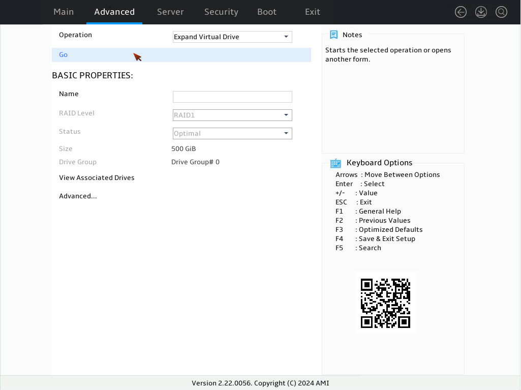
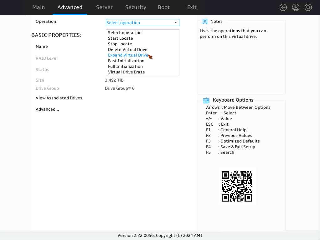
3. On the screen as shown in Figure 4, select Operation and press Enter. In the dialog box that opens, select Expand Virtual Drive and press Enter.

4. On the screen as shown in Figure 5, select Go and press Enter.
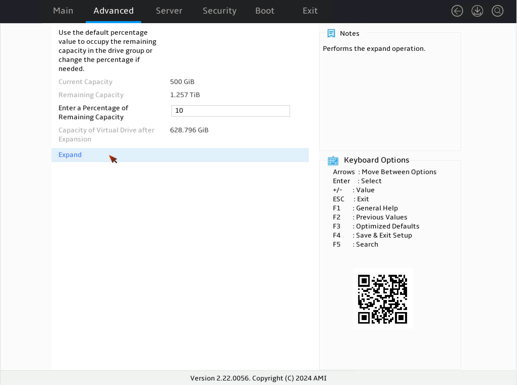
5. On the screen as shown in Figure 6, modify the value for Enter a Percentage of Remaining Capacity, select Expand, and then press Enter.
Figure 118 Setting the percentage of remaining capacity
6. When the operation is complete, the screen as shown in Figure 7 opens. Select OK, and then press Enter.
Figure 119 Completing expanding a RAID array

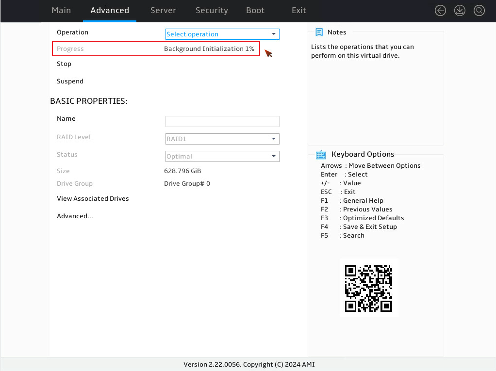
7. On the screen as shown in Figure 8, view the background initialization progress in the Background Initialization x% field.
Figure 120 Background initialization progress
Adding new physical drives to the array
|
|
NOTE: · Drive space expansion by adding new physical drives to the array is available only for RAID levels 0, 1, 5, and 6 in UEFI mode or in the OS. · The newly added physical drives must match the interface protocol and media type for member drives of the RAID array. Make sure the capacity of each new drive is not smaller than the minimum capacity of the drives in the RAID array. · The maximum number of member drives in RAID levels 0, 5, and 6 is 32. |
To add new physical drives to the array:
1. On the storage controller configuration screen as shown in Figure 9, select Virtual Drive Management and press Enter.
Figure 121 Storage controller configuration screen

2. On the screen as shown in Figure 10, select the target drive and press Enter.
Figure 122 Virtual Drive Management screen

3. On the screen as shown in Figure 11, select Operation and press Enter. In the dialog box that opens, select Expand Virtual Drive and press Enter.
4. On the screen as shown in Figure 12, select Go and press Enter.

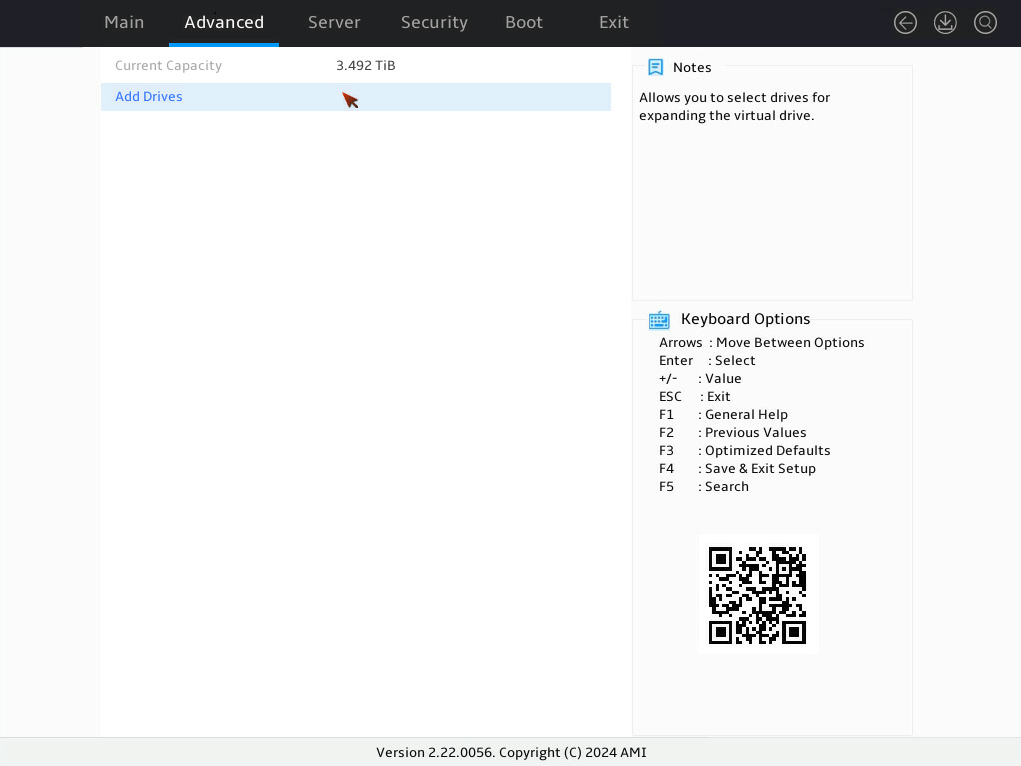
5. On the screen as shown in Figure 13, select Add Drives, and then press Enter.
Figure 125 Selecting Add Drives
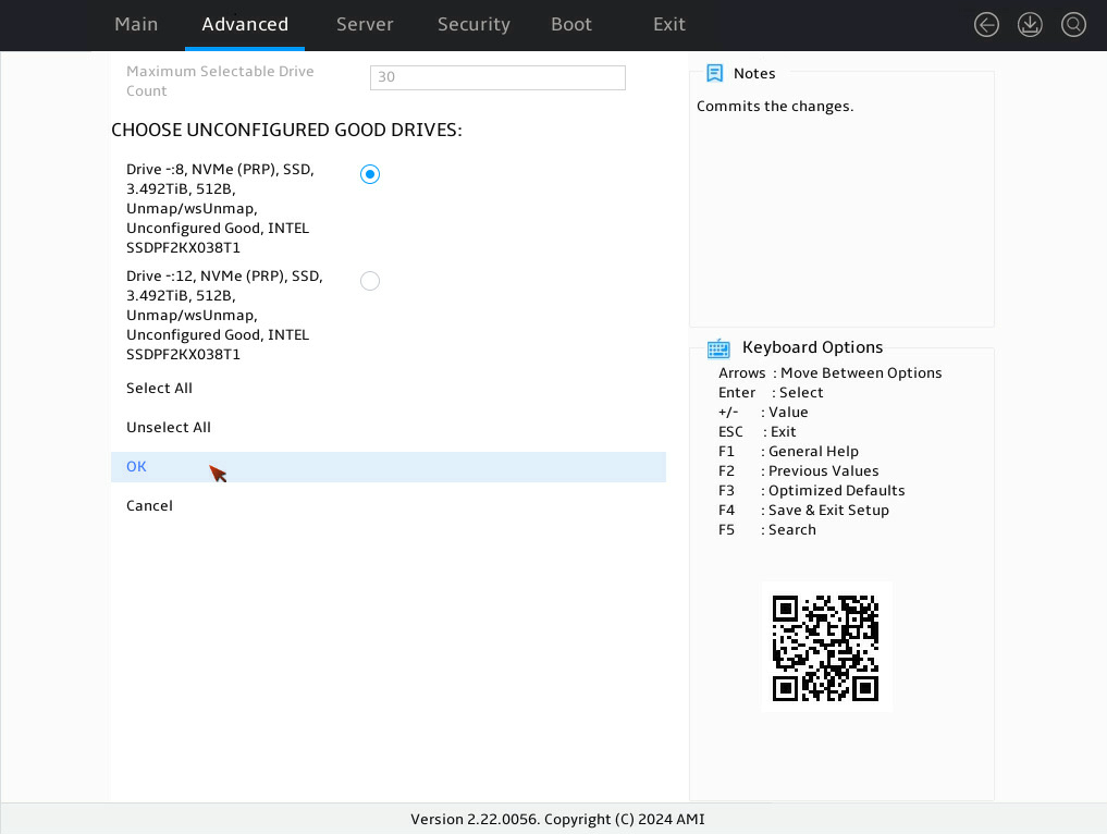
6. On the screen as shown in Figure 14, select the target drives. ([Enabled] following the drive means that the drive has been selected.) Select OK, and then press Enter.
Figure 126 CHOOSE UNCONFIGURED GOOD DRIVES screen
7. On the screen as shown in Figure 15, select OK, and then press Enter.

8. On the screen as shown in Figure 16, select Expand, and then press Enter.

9. When the operation is complete, the screen as shown in Figure 17 opens. Select OK, and then press Enter.
Figure 129 Completing expanding a RAID array

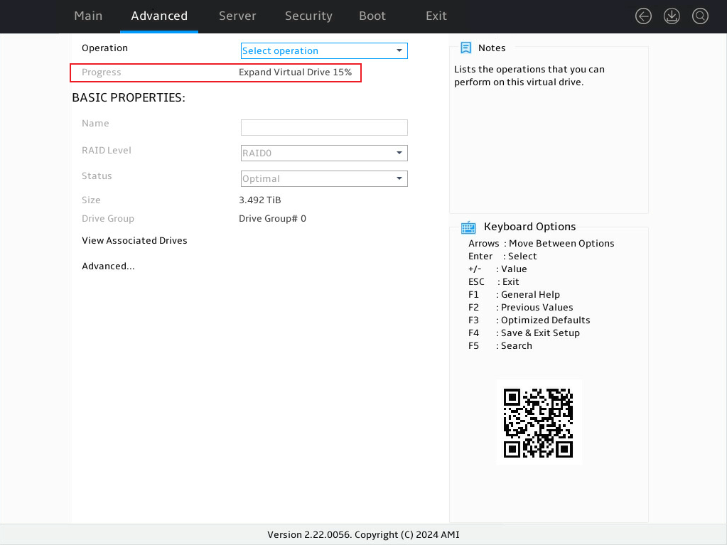
10. On the screen as shown in Figure 18, view the virtual drive expansion progress in the Expand Virtual Drive x%.
Forcing a logical drive to come online
When the number of faulty drives exceeds the tolerance range of the logical drive fault-tolerant method, the Virtual Drive Management menu displays the state of the logical drives as Offline. In this case, you can use this feature to force the logical drive to come online.
|
|
CAUTION: Forcing a physical drive to come online will change the status of the logical drive to which the physical drive is attached, and any background tasks for the logical drive will be aborted. This feature might cause file data loss. Before forcing a logical drive to come online, back up ddata as needed and evaluate the impact of the operation. |
To force a logical drive to come online:
1. On the screen as shown in Figure 19, select Virtual Drive Management and then press Enter.
Figure 131 Storage controller screen

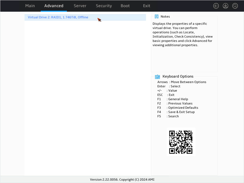
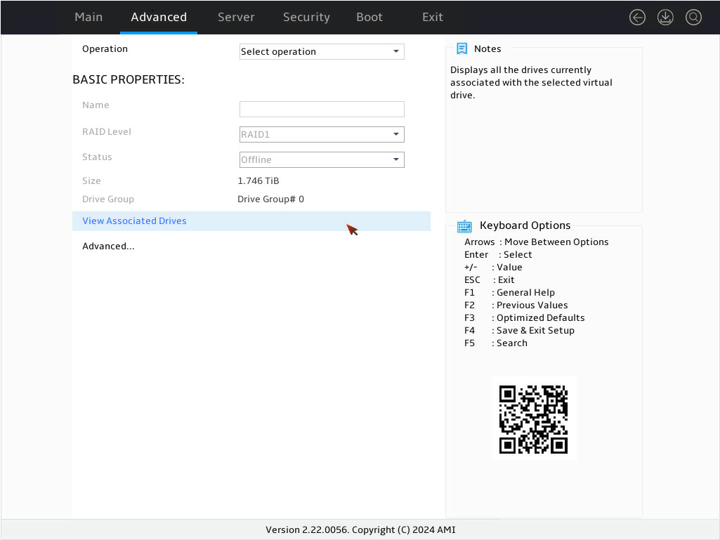
2. On the screen as shown in Figure 20, select the target logical drive, and then press Enter.
Figure 132 Virtual Drive Management screen
3. On the screen as shown in Figure 21, select View Associated Drives and then press Enter.
Figure 133 Selecting View Associated Drives
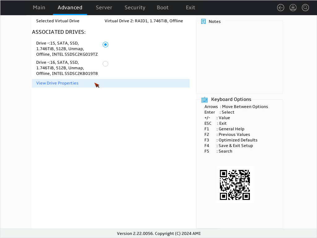
4. On the screen as shown in Figure 22, select the target offline member drive and press Enter to enable the drive. Then, select View Drive Properties and press Enter.
Figure 134 Selecting View Drive Properties
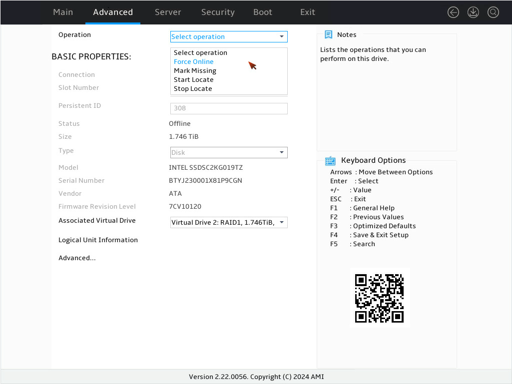
5. On the screen as shown in Figure 23, select Operation, press Enter, select Force Online, and then press Enter again.
Figure 135 Selecting Force Online
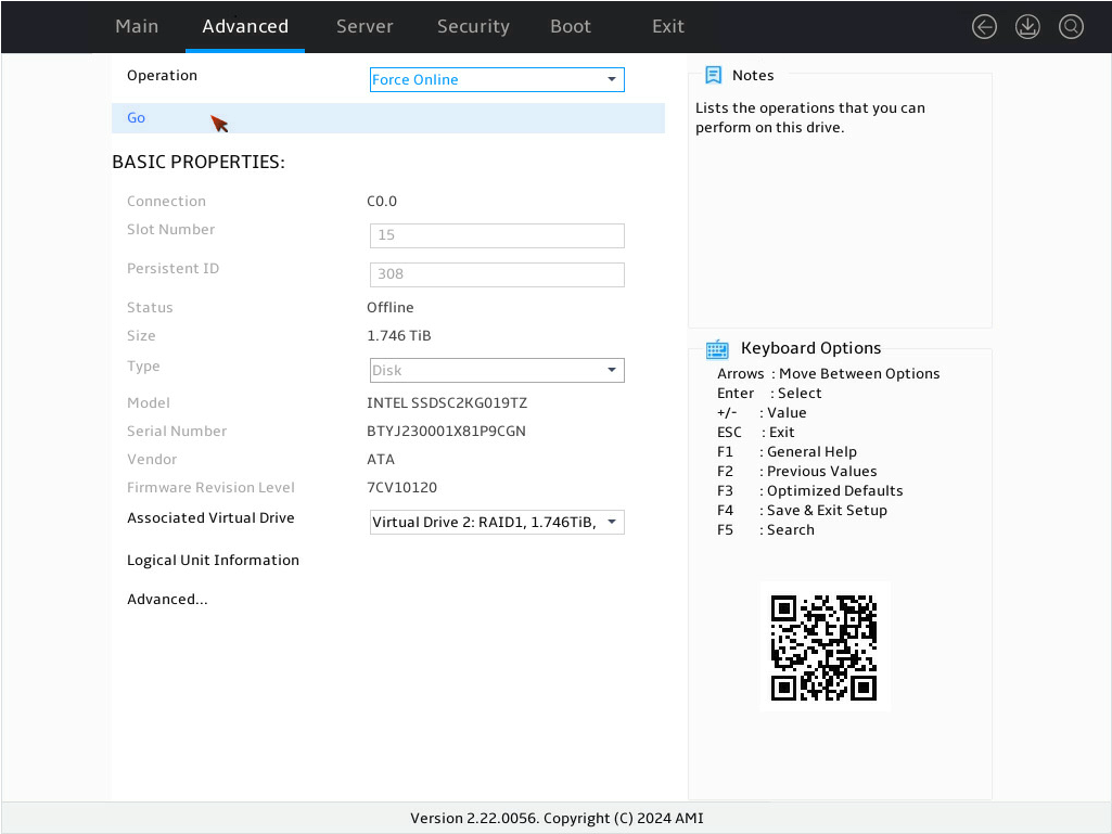
6. On the screen as shown in Figure 24, select Go and then press Enter.
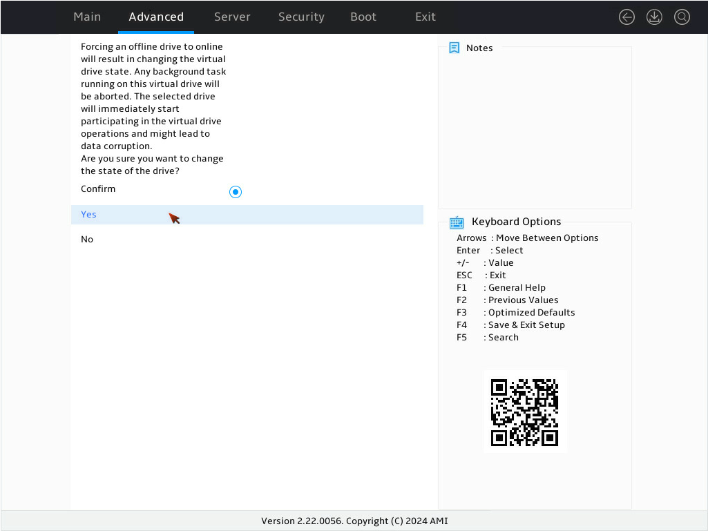
7. On the screen as shown in Figure 25, select Confirm and press Enter to enable the drive. Then, select Yes and press Enter.
Figure 137 Confirming the operation
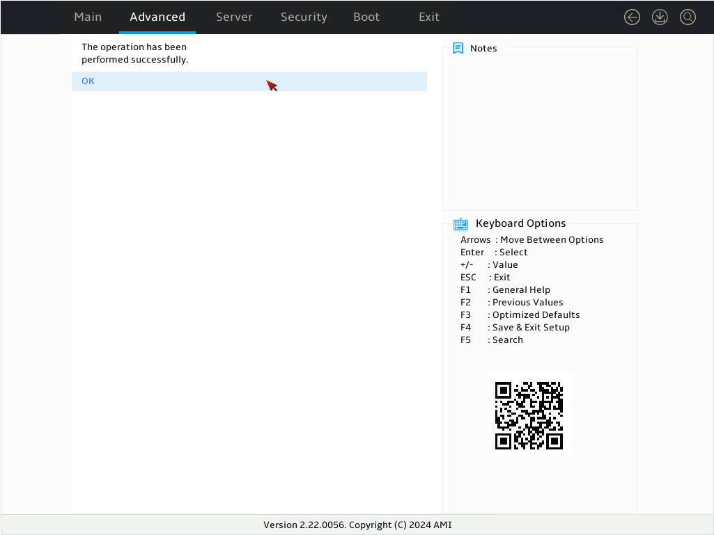
8. On the screen as shown in Figure 26, select OK and press Enter.
Figure 138 Operation succeeded
Viewing storage controller properties
1. On the storage controller configuration screen as shown in Figure 27, select Controller Management and press Enter.
Figure 139 Storage controller configuration screen

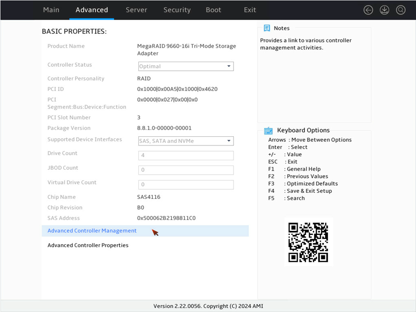
2. On the screen as shown in Figure 28, view the basic storage controller information and press Enter. For more information about storage controller properties, see Table 5.
Figure 140 Virtual Drive Management screen
|
Parameter |
Description |
|
Product Name |
Storage controller name. |
|
Product Name |
Name of the storage controller. |
|
Controller Status |
Operating status of the storage controller. |
|
Controller Personality |
Mode of the storage controller. |
|
PCI ID |
PCI ID of the storage controller. |
|
PCI Segment:Bus:Device:Fuction |
PCI address of the storage controller in the format of bus number:device number:function number. |
|
PCI Slot Number |
PCIe slot number of the storage controller. |
|
Package Version |
Firmware package version of the storage controller. |
|
Supported Device Interfaces |
PSOC firmware version of the storage controller. |
|
Drive Count |
Number of the drives attached to the storage controller. |
|
JBOD Count |
Number of the physical drives in JBOD status attached to the storage controller. |
|
Virtual Drive Count |
Number of virtual drives that are already attached to the storage controller. |
|
Chip Name |
Name of the chip in the storage controller. |
|
Chip Revision |
Revision of the chip in the storage controller. |
|
Chip Address |
SAS address of the chip in the storage controller. |
|
Advanced Controller Management |
List all management properties and options for the storage controller. |
|
Advanced Controller Properties |
List all properties and options for the storage controller. |
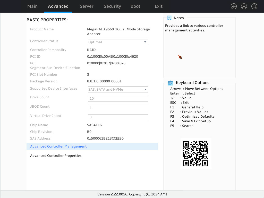
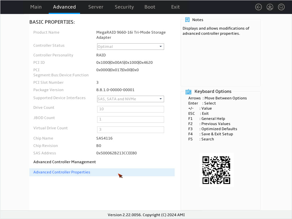
3. On the storage controller management screen as shown in Figure 29, select Advanced Controller Properties and press Enter.
Figure 141 Selecting Advanced Controller Properties screen
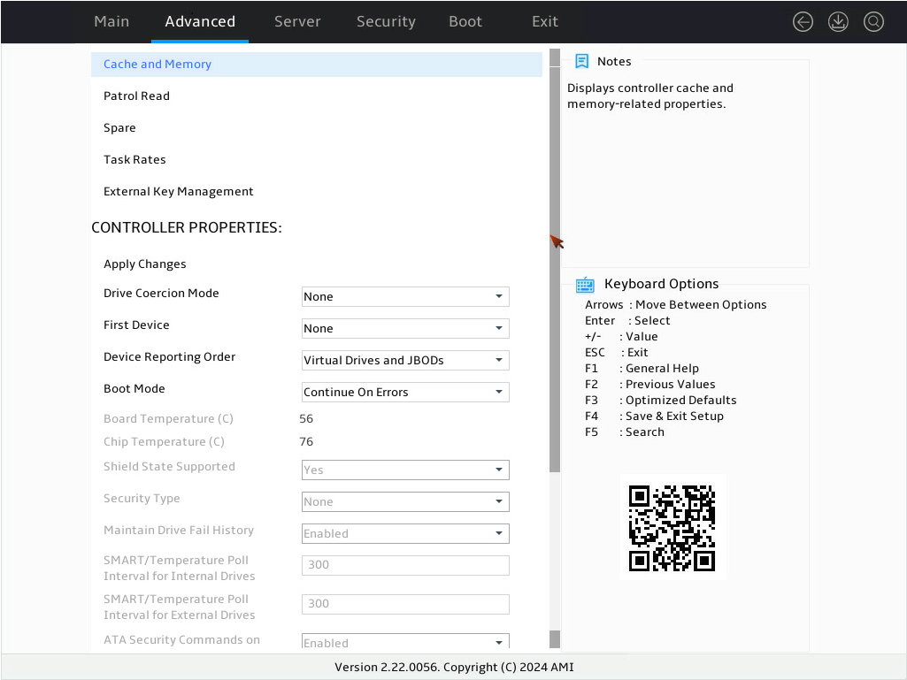
4. On the screen as shown in Figure 30, view and edit the advanced properties of the storage controller. For more information, see Table 6.
Figure 142 Advanced properties screen for the storage controller
|
Parameter |
Description |
|
Cache and Memory |
Cache and memory properties of the storage controller. |
|
Patrol Read |
View and edit the percentage of storage controller resources for patrol operations and the correction method for unconfigured areas. |
|
Spare |
Edit properties related with emergency hot spare, hot spare, and drive replacement. |
|
Task Rates |
View and edit the percentage of storage controller resources for various operations. |
|
External Key Management |
N/A |
|
Drive Coercion Mode |
Specify the capacity compression mode of drives. |
|
First Device |
Specify the first device to report. |
|
Device Reporting Order |
· Virtual Drives and JBODs—The storage controller reports devices in the order of logical drives followed by passthrough drives when a server restarts. This is the default option. · JBODs and Virtual Drives—The storage controller changes the reporting order of devices by reporting, passthrough drives before logical drives when a server restarts. In the configuration of the storage controller, the First Device option takes priority over the Device Reporting Order option. If the first device is configured, the firmware will report the first device first, followed by the remaining drives according to the device reporting order configuration. |
|
Boot Mode |
Specify the action to be taken when the BIOS detects an exception. Options include: · Continue On Errors—The controller firmware attempts to continue startup when detecting an exception, but switches to safe mode if critical issues cannot be bypassed. This is the default option. · Safe Mode on Errors—The controller firmware uses the safe startup mode when detecting an exception. |
|
Board Temperature (C) |
Board temperature of the storage controller. |
|
Chip Temperature (C) |
Chip temperature of the storage controller. |
|
Shield State Supported |
Select whether to support I/O interruption for drive diagnosis. The default is Yes. |
|
Security Type |
Encryption type of the controller. |
|
Maintain Drive Fail History |
Select whether to enable drive fault recording. The default is Enabled, and modification is not supported. If this field is set to Enabled, the following rules apply: · If a new drive that does not contain RAID configuration is installed, the drive will automatically rebuild the data of the faulty drive. · When you install a new drive with RAID configuration or hot swap a drive in the RAID array, the drive status will be marked as Unconfigured Good (Foreign) and the rebuild operation will not be automatically performed. To rebuild RAID for this drive, set the drive status to Unconfigured Good. For more information, see "Importing foreign configuration._Ref148447615" |
|
ATA Security Commands on JBOD |
Select whether to enable drive ATA security commands on JBOD. The default is Enabled, and modification is not supported. |
|
Stop Consistency Check on Error |
Select whether to stop consistency check upon errors. |
|
Device Discovery in Core BSD |
Specify whether the UEFI BSD (Boot Service Driver) should register devices for Block IO and EXT SCSI passthrough access. Options include: · All—Both the storage controller and its connected devices will be registered. · None—Only the storage controller will be registered. The devices connected to the storage controller will not be registered in the UEFI interface. · Internal—The storage controller and internal system devices will be registered. This is the default option. |
|
Apply Changes |
N/A |
|
Display of some parameters depends on the storage controller firmware. |
|
Importing foreign configuration
Perform this task to import the configuration of an old storage controller to a new storage controller after the old storage controller is replaced.
Restrictiond and guidelines
After you replace a storage controller on a server configured with RAID, the system identifies current RAID configuration as Foreign Configuration. In this case, if you clear foreign configuration, the RAID configuration will get lost.
When the number of failed or missing drives exceeds the maximum allowable by a RAID array, the RAID array cannot be imported successfully.
The RAID configuration of the LSI MR96 storage controller is mutually exclusive with configurations of the LSI MR93, LSI MR94, and LSI MR95 controllers, preventing the import of external configuration information between them.
Procedure
1. On the storage controller configuration screen as shown in Figure 31, select Configuration Management and press Enter.
Figure 143 Storage controller configuration screen

2. On the screen as shown in Figure 32, view the current detailed foreign configuration.
Figure 144 Manage Foreign Configuration screen

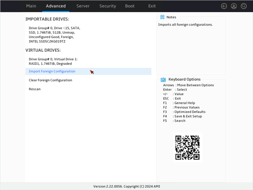
3. On the screen as shown in Figure 33, select Import Foreign Configuration and press Enter.
Figure 145 Selecting Import Foreign Configuration
4. On the screen as shown in Figure 34, select Confirm and press Enter. Then, select Yes and press Enter.
Figure 146 Confirming the operation

5. On the screen as shown in Figure 35, select OK and press Enter.
Figure 147 Completing importing the foreign configuration

Clearing RAID array information on the drive
This task allows you to clear remaining RAID array information on the drive for reconfiguring RAID array on the drive.
Procedure
1. On the storage controller configuration screen as shown in Figure 36, select Configuration Management and press Enter.
Figure 148 Storage controller configuration screen

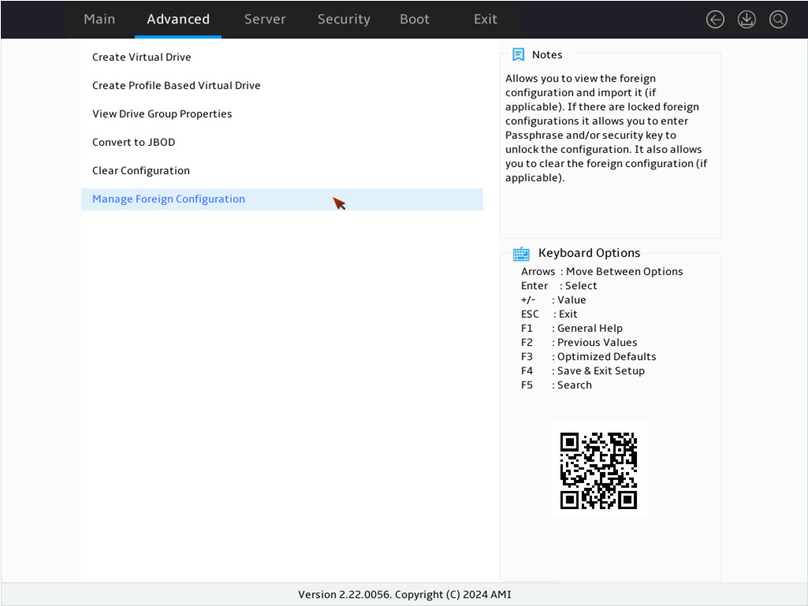
2. On the screen as shown in Figure 37, select Manage Foreign Configuration and press Enter.
Figure 149 Selecting Manage Foreign Configuration
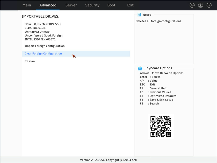
3. On the screen as shown in Figure 38, select Clear Foreign Configuration and press Enter.
Figure 150 Selecting Clear Foreign Configuration
4. On the screen as shown in Figure 39, select Confirm and press Enter. Then, select Yes and press Enter.
Figure 151 Confirming the operation
5. On the screen as shown in Figure 40, select OK and press Enter.
Figure 152 Completing the operation
Creating multiple virtual drives
Procedure
1. On the storage controller configuration screen as shown in Figure 41, select Configuration Management and press Enter.
Figure 153 Storage controller configuration screen
2. On the screen as shown in Figure 42, select Create Virtual Drive and press Enter.
Figure 154 Selecting Create Virtual Drive
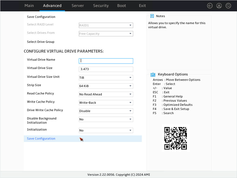
3. On the screen as shown in Figure 43, select Select RAID Level to set the RAID level, for example RAID 1, and then press Enter.
Figure 155 Setting the RAID level
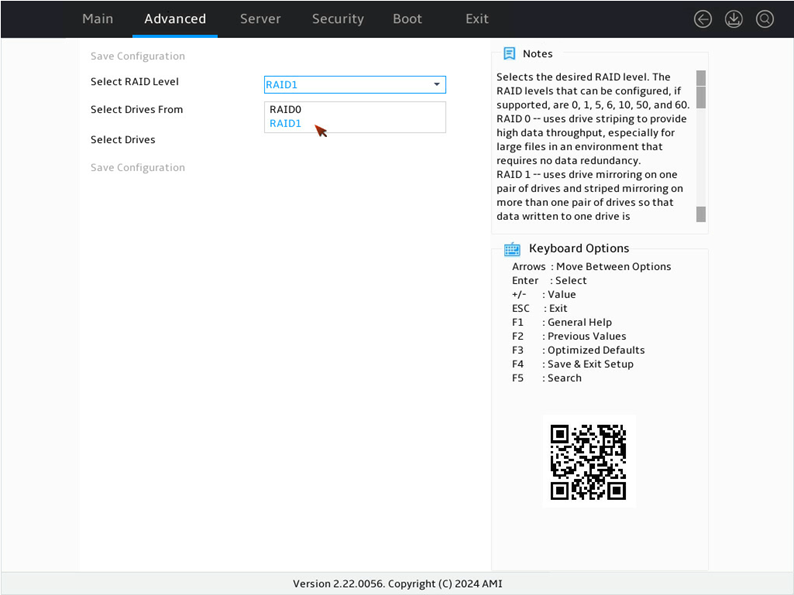
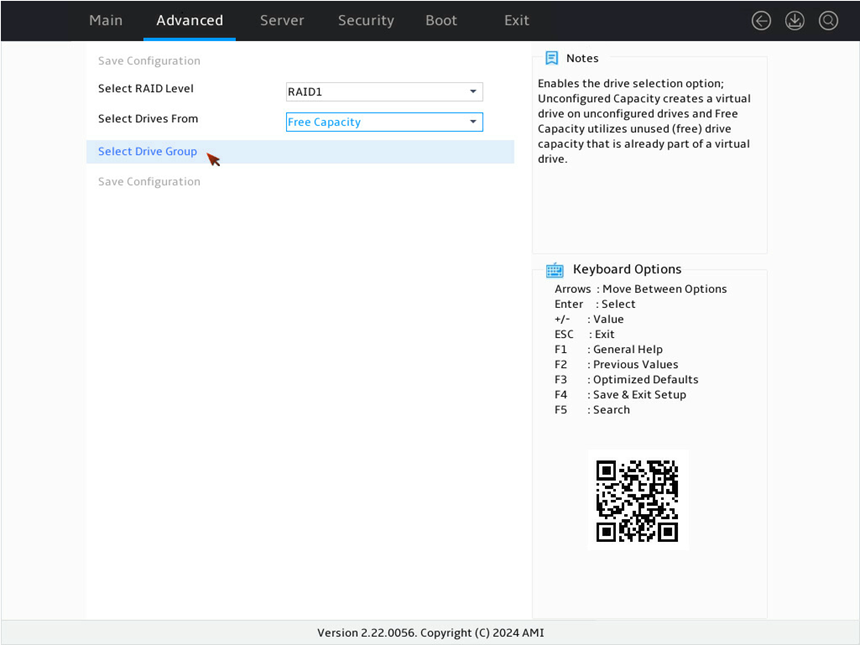
4. On the screen as shown in Figure 44, select Select Drives From to set the drive capacity source, select Free Capacity, which indicates that the capacity source is the remaining drive capacity of the drives that have been used for RAID setup. Then, press Enter.
Figure 156 Selecting Select Drives From

5. On the screen as shown in Figure 45, select Select Drives Group, and then press Enter.
Figure 157 Selecting Select Drives Group
6. On the screen as shown in Figure 46, select Drives Group x, Free Space x, and press Enter.
Figure 158 CHOOSE DRIVE GROUP section
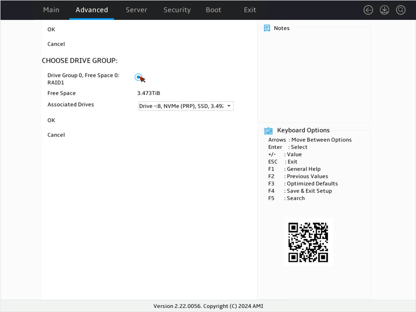
7. On the screen as shown in Figure 47, select OK and press Enter.
Figure 159 Selecting OK
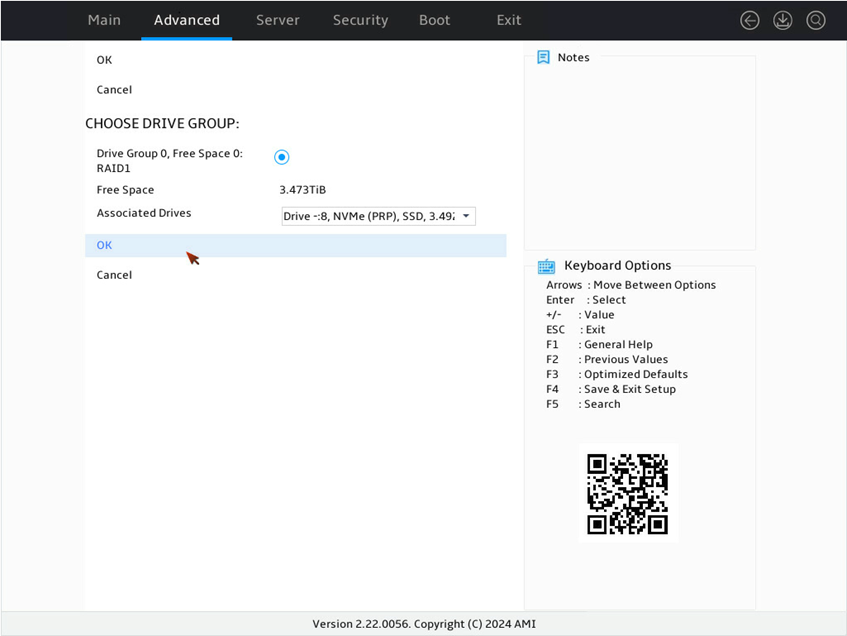
8. On the screen as shown in Figure 48, select OK and press Enter.
Figure 160 Completing the operation

9. On the screen as shown in Figure 49, select Save Configuration, and then press Enter.
Figure 161 Selecting Save Configuration
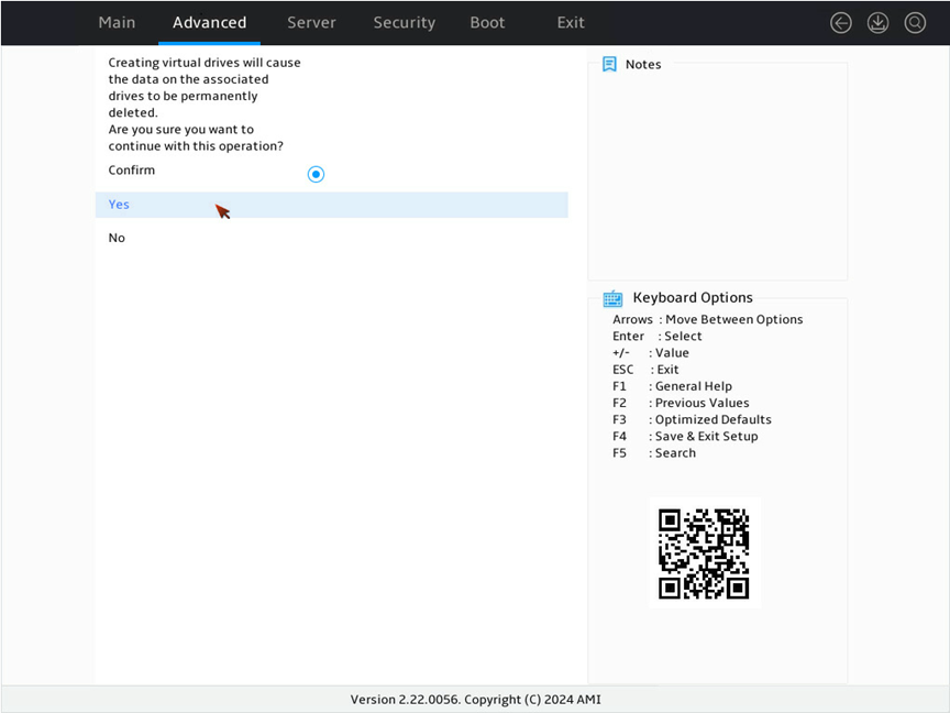
10. On the screen as shown in Figure 50, select Confirm and press Enter. Then, select Yes and press Enter.
Figure 162 Confirming the operation
11. On the screen as shown in Figure 51, select OK and press Enter.
Figure 163 Completing the configuration

Converting drives to JBOD state
Perform this task to change the state of multiple drives to JBOD in the BIOS.
|
|
NOTE: This feature is unavailable if no physical drives in Unconfigured Good state are present for a storage controller. |
Procedure
1. On the screen as shown in Figure 52, select Configuration Management and then press Enter.
Figure 164 Storage controller configuration screen

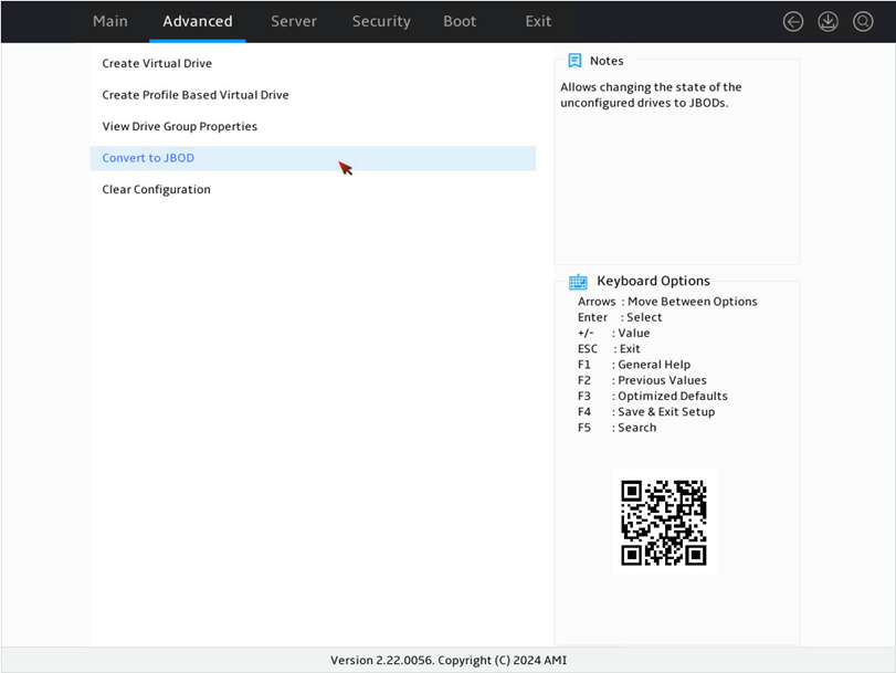
2. On the screen as shown in Figure 53, select Convert to JBOD and press Enter.
Figure 165 Configuration Management screen
3. On the screen as shown in Figure 54, select the target drives, press Enter. Then, select OK and press Enter.
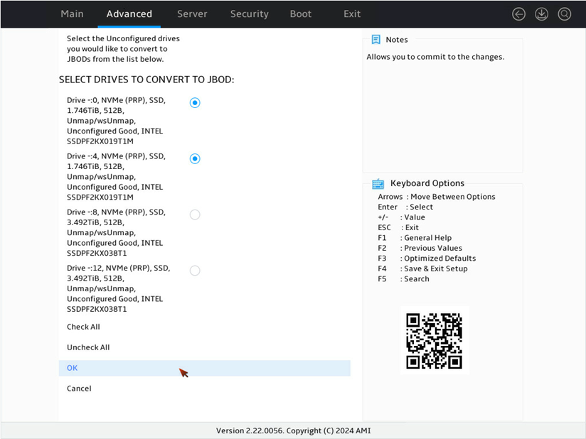
4. On the screen as shown in Figure 55, select OK and press Enter.
Figure 167 Completing the operation

Converting drives to Unconfigured state
Perform this task to change the state of multiple drives to Unconfigured in the BIOS.
|
|
NOTE: This feature is unavailable when no physical drives in the JBOD state are present for a storage controller. If the the physical drives in JBOD state has data, verify and back up the data before switching the drive state. |
Procedure
1. On the screen as shown in Figure 56, select Configuration Management and then press Enter.
Figure 168 Storage controller configuration screen

2. On the screen as shown in Figure 57, select Convert to Unconfigured and press Enter.
Figure 169 Configuration Management screen

3. On the screen as shown in Figure 58, select the target drives, press Enter. Then, select OK and press Enter.
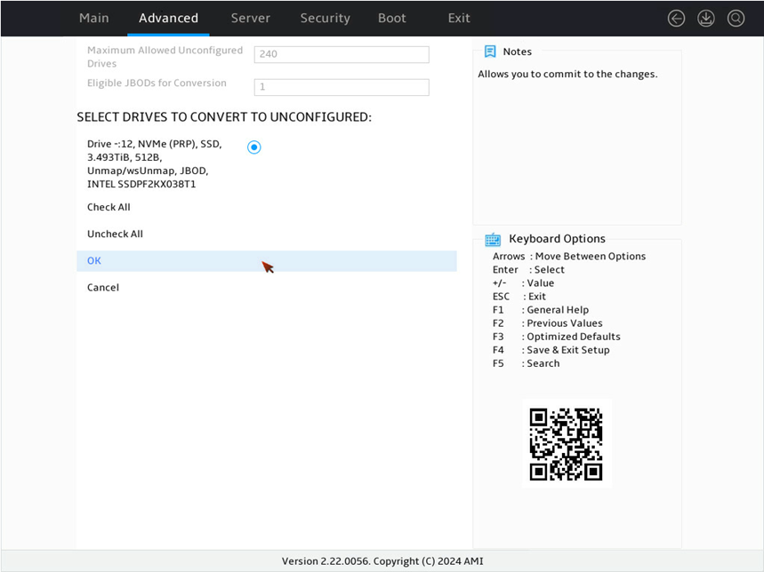
4. On the screen as shown in Figure 59, select OK and press Enter.
Figure 171 Completing the operation
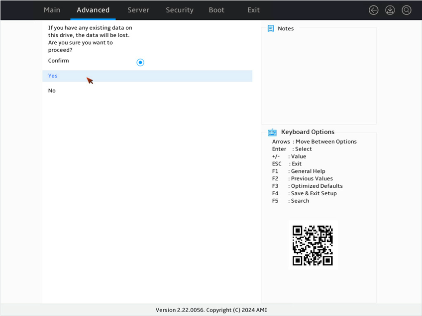
5. On the screen as shown in Figure 60, select OK and press Enter.
Figure 172 Completing the operation

Configuring the Auto-Configure Behavior (Primary) feature
Perform this task to set the automatic configuration behavior of storage controllers. When you enable this feature, the newly installed physical drives will be automatically configured.
|
|
NOTE: The primary auto-configure behavior feature does not apply to physical drives that are already attached to a storage controller. For example, if you set Auto-Configure Behavior (Primary) to JBOD and a physical drive in Unconfigured Good state is re-installed, the physical drive will remain in Unconfigured Good state. This is because the storage controller knows the drive, and the primary auto-configure behavior feature does not take effect on such a drive. The Single Drive RAID 0 option indicates a single drive in RAID 0 with write cache policy as Write Through. The Single Drive RAID 0 WB option indicates a single drive in RAID 0 with write cache policy as Write Back. |
Procedure
1. On the screen as shown in Figure 61, select Configuration Management, and then press Enter.
Figure 173 Storage controller configuration screen
2. On the screen as shown in Figure 62, select Advanced Controller Management and press Enter.
Figure 174 Selecting Advanced Controller Management

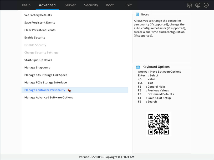
3. On the screen as shown in Figure 63, select Manage Controller Personality and press Enter.
Figure 175 Selecting Manage Controller Personality

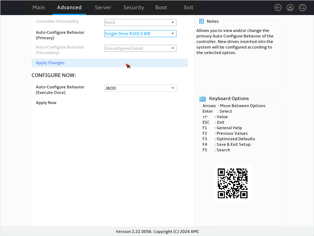
4. On the screen as shown in Figure 64, select Auto-Configure Behavior (Primary) and press Enter. In the dialog box that opens, select Single Drive RAID 0 WB for the Auto-Configure Behavior (Primary) field and press Enter.
Figure 176 Manage Controller Personality screen
5. On the screen as shown in Figure 65, select Apply Changes and press Enter.
Figure 177 Applying the configuration
6. On the screen as shown in Figure 66, select Confirm and press Enter. Then, select Yes and press Enter
Figure 178 Confirming the operation

7. On the screen as shown in Figure 67 select OK and press Enter.
Figure 179 Completing the operation

Configuring the Auto-Configure Behavior (Execute-Once) feature
Perform this task to change the state of multiple drives to JBOD, Single Drive RAID 0, or Single Drive RAID 0 WB in the BIOS.
|
|
NOTE: The Single Drive RAID 0 option indicates a single drive in RAID 0 with write cache policy as Write Through. The Single Drive RAID 0 WB option indicates a single drive in RAID 0 with write cache policy as Write Back. |
Procedure
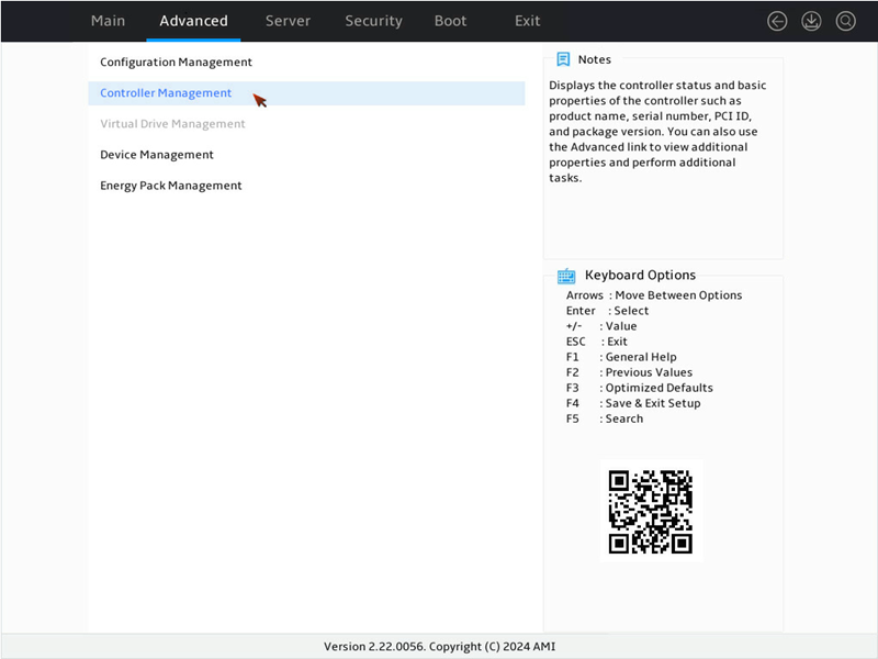
1. On the screen as shown in Figure 68, select Controller Management and then press Enter.
Figure 180 Storage controller configuration screen

2. On the screen as shown in Figure 69, select Advanced Controller Management and press Enter.
Figure 181 Selecting Advanced Controller Management
3. On the screen as shown in Figure 70, select Manage Controller Personality and press Enter.
Figure 182 Selecting Manage Controller Personality
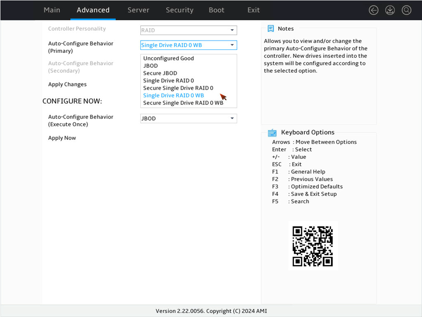
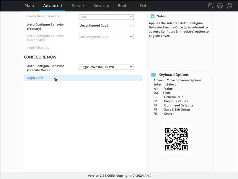
4. On the screen as shown in Figure 71, select Auto-Configure Behavior (Execute-Once) and press Enter. In the dialog box that opens, select Single Drive RAID 0 WB for the Auto-Configure Behavior (Execute-Once) field and press Enter.
Figure 183 Manage Controller Personality screen
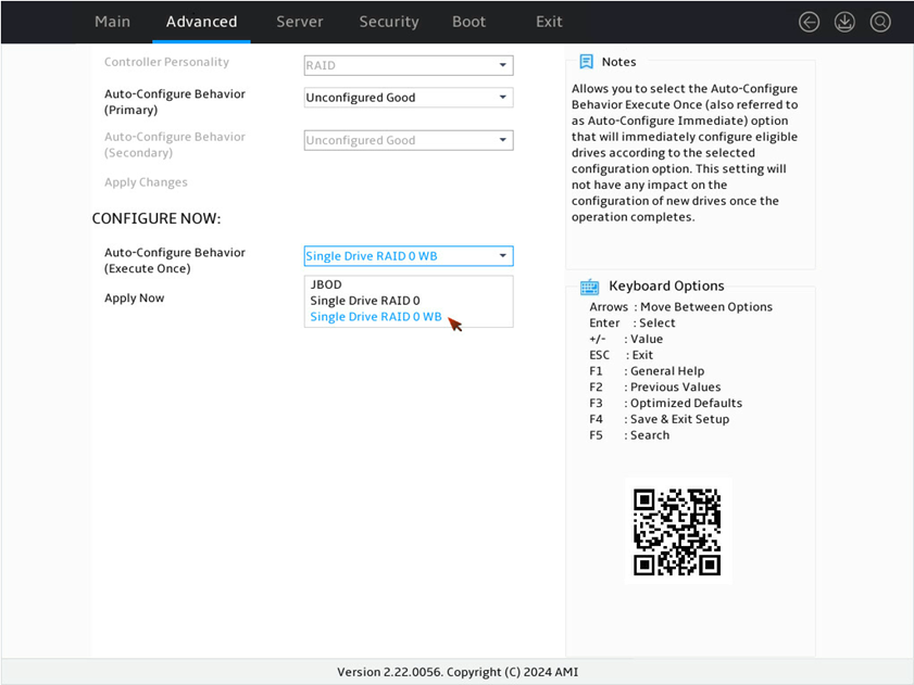
5. On the screen as shown in Figure 72, select Apply Now and press Enter.
Figure 184 Applying the configuation
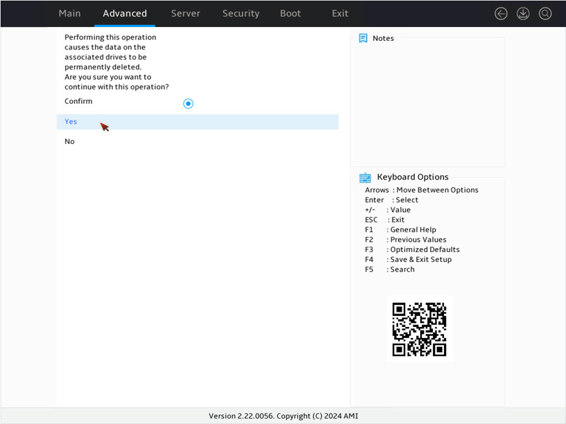
6. On the screen as shown in Figure 73, select Confirm and press Enter. Then, select Yes and press Enter.
Figure 185 Confirming the operation
7. On the screen as shown in Figure 74 select OK and press Enter.
Figure 186 Completing the operation

Configuring RAID arrays in legacy mode
The storage controllers in this section do not support legacy mode and the management interface in legacy mode.
Downloading and installing StorCLI
This section introduces the download and installation steps of the OS command line tool. You can use the OS command line tool to manage storage controllers during normal server operation without restarting the server.
Downloading StorCLI
1. Access https://www.h3c.com/cn/BizPortal/DownLoadAccessory/DownLoadAccessoryFilt.aspx.
2. Download the installation package and release notes for the corresponding storage controller firmware as instructed.
3. Decompress the installation package to obtain the StorCLI2 tool package for different operating systems.
Installing StorCLI
See the release notes to install StorCLI2 for the corresponding operating system.
Commonly-used commands in StorCLI
This section describes the usage and examples of commonly used commands in StorCLI. You can use the OS command line tool to manage storage controllers during normal server operation without restarting the server.
|
|
NOTE: All the commands related with specifying paths in StorCLI do not support spaces and special characters. |
Viewing storage controller information
Perform this task to view basic information about an LSI storage controller.
Syntax
storcli2 show
storcli2 /cController_Index show [logfile=logfilename]
storcli2 /cController_Index show all [logfile=logfilename]
Parameters
controller_Index: Specifies the index of a storage controller. If only one storage controller exists, the index is 0 by default. If multiple storage controllers exist, use the storcli2 show command to view the controller index.
logfilename: Specifies the name of the file to save the filtered information.
Examples
# View controller indexes of storage controllers.
[root@localhost ~]# storcli2 show
CLI Version = 008.0008.0000.0010 Jan 08, 2024
Operating system = Linux5.14.0-70.22.1.el9_0.x86_64
Status Code = 0
Status = Success
Description = None
Number of Controllers = 1
Host Name = localhost.localdomain
Operating System = Linux5.14.0-70.22.1.el9_0.x86_64
SL8 Library Version = 08.0807.0000
System Overview :
===============
-----------------------------------------------------------------------------------------------------------------
Ctrl Product Name SASAddress Personality Status PD(s) VD(s) VNOpt EPack
-----------------------------------------------------------------------------------------------------------------
0 MegaRAID 9660-16i Tri-Mode Storage Adapter 0X500062B213CCEE80 RAID Optimal 2 1 0 Optimal
-----------------------------------------------------------------------------------------------------------------
Ctrl=Controller Index|Health=Controller Health|PD(s)=Physical Drives
VD(s)=Virtual Drive(s)|VNOpt=VD Not Optimal|EPack=Energy Pack|Unkwn=Unknown
# View basic information about a storage controller.
[root@localhost ~]# storcli2 /c0 show
CLI Version = 008.0008.0000.0010 Jan 08, 2024
Operating system = Linux5.14.0-70.22.1.el9_0.x86_64
Controller = 0
Status = Success
Description = None
Product Name = MegaRAID 9660-16i Tri-Mode Storage Adapter
Board Name = MR 9660-16i
Board Assembly = 03-50107-00001
Board Tracer Number = SPC5104545
Board Revision = 00001
Chip Name = SAS4116
Chip Revision = B0
Package Version = 8.8.1.0-00000-00001
Firmware Version = 8.8.1.0-00000-00001
Firmware Security Version Number = 00.00.00.00
NVDATA Version = 08.0E.00.54
Driver Name = mpi3mr
Driver Version = 8.8.1.0.0
SAS Address = 0x500062b213ccee80
Serial Number = SPC5104545
Controller Time(LocalTime yyyy/mm/dd hh:mm:sec) = 2024/04/09 03:39:20
System Time(LocalTime yyyy/mm/dd hh:mm:sec) = 2024/04/09 03:39:20
Board Mfg Date(yyyy/mm/dd) = 2022/12/30
Controller Personality = RAID
Max PCIe Link Rate = 0x08 (16GT/s)
Max PCIe Port Width = 8
PCI Address = 00:17:00:0
PCIe Link Width = X8 Lane(s)
SAS/SATA = SAS/SATA-6G, SAS-12G, SAS-22.5G
PCIe = PCIE-2.5GT, PCIE-5GT, PCIE-8GT, PCIE-16GT
PCI Vendor ID = 0x1000
PCI Device ID = 0x00A5
PCI Subsystem Vendor ID = 0x1000
PCI Subsystem ID = 0x4620
Security Protocol = SPDM-1.1.0,1.0.0
PCI Slot Number = 3
Drive Groups = 1
TOPOLOGY :
========
-------------------------------------------------------------------------------
DG Span Row EID:Slot PID Type State Status BT Size PDC Secured FSpace
-------------------------------------------------------------------------------
0 - - - - RAID1 - - N 558.406 GiB dsbl N N
0 0 - - - RAID1 - - N 558.406 GiB dsbl N N
0 0 0 292:12 287 DRIVE Conf Online N 558.406 GiB dsbl N -
0 0 1 292:13 288 DRIVE Conf Online N 558.406 GiB dsbl N -
-------------------------------------------------------------------------------
DG-Drive Group Index|Span-Span Index|Row-Row Index|EID-Enclosure Persistent ID
PID-Persistent ID|Slot-Slot Number|Type-Drive Type|Onln-Online|Rbld-Rebuild|Dgrd-Degraded
Pdgd-Partially degraded|Offln-Offline|BT-Background Task Active
PDC-Drive Write Cache Policy|Frgn-Foreign|Optl-Optimal|FSpace-Free Space Present
dflt-Default|Msng-Missing
Virtual Drives = 1
VD LIST :
=======
--------------------------------------------------------------------
DG/VD TYPE State Access CurrentCache DefaultCache Size Name
--------------------------------------------------------------------
0/1 RAID1 Optl RW R,WB R,WB 558.406 GiB
--------------------------------------------------------------------
Rec=Recovery|OfLn=OffLine|Pdgd=Partially Degraded|Dgrd=Degraded
Optl=Optimal|RO=Read Only|RW=Read Write|CurrentCache-Curent Cache Status
R=Read Ahead Always|NR=No Read Ahead|WB=WriteBack|
AWB=Always WriteBack|WT=WriteThrough|Access-Access Policy
Physical Drives = 2
PD LIST :
=======
-------------------------------------------------------------------------------------------------------
EID:Slt PID State Status DG Size Intf Med SED_Type SeSz Model Sp LU/NS Count Alt-EID
-------------------------------------------------------------------------------------------------------
292:12 287 Conf Online 0 558.406 GiB SAS HDD - 512B ST600MM0009 U 1 -
292:13 288 Conf Online 0 558.406 GiB SAS HDD - 512B ST600MP0006 U 1 -
-------------------------------------------------------------------------------------------------------
LU/NS LIST :
==========
--------------------------------------
PID LUN/NSID Index Status Size
--------------------------------------
287 0/- 0 Online 558.406 GiB
288 0/- 0 Online 558.406 GiB
--------------------------------------
EID-Enclosure Persistent ID|Slt-Slot Number|PID-Persistent ID|DG-DriveGroup
UConf-Unconfigured|UConfUnsp-Unconfigured Unsupported|Conf-Configured|Unusbl-Unusable
GHS-Global Hot Spare|DHS-Dedicated Hot Spare|UConfShld-Unconfigured Shielded|
ConfShld-Configured Shielded|Shld-JBOD Shielded|GHSShld-GHS Shielded|DHSShld-DHS Shielded
UConfSntz-Unconfigured Sanitize|ConfSntz-Configured Sanitize|JBODSntz-JBOD Sanitize|GHSSntz-GHS Sanitize
DHSSntz-DHS Sanitize|UConfDgrd-Unconfigured Degraded|ConfDgrd-Configured Degraded|JBODDgrd-JBOD Degraded
GHSDgrd-GHS Degraded|DHSDgrd-DHS Degraded|Various-Multiple LU/NS Status|Med-Media|SED-Self Encryptive Drive
SeSz-Logical Sector Size|Intf-Interface|Sp-Power state|U-Up/On|D-Down/PowerSave|T-Transitioning|F-Foreign
NS-Namespace|LU-Logical Unit|LUN-Logical Unit Number|NSID-Namespace ID|Alt-EID-Alternate Enclosure Persistent ID
Enclosures = 1
Enclosure List :
==============
-------------------------------------------------------------------------------------------------
EID State DeviceType Slots PD Partner-EID Multipath PS Fans TSs Alms SIM ProdID
-------------------------------------------------------------------------------------------------
292 OK Logical Enclosure 16 2 - No 0 0 0 0 0 VirtualSES
-------------------------------------------------------------------------------------------------
EID-Enclosure Persistent ID |SID-Slot ID |PID-Physical drive Persistent ID |PD-Physical drive count
PS-Power Supply count |TSs-Temperature sensor count |Alms-Alarm count |SIM-SIM Count |ProdID-Product ID
ConnId-ConnectorID
Energy Pack Info :
================
----------------------------------------------------
Type SubType Voltage(mV) Temperature(C) Status
----------------------------------------------------
Supercap FBU345 9359 44 Optimal
----------------------------------------------------
# View all information of the storage controller and save the information to the specified file.
[root@localhost ~]# storcli2 /c0 show all logfile=logfile.txt
Updating the storage controller firmware
Perform this task to update the firmware of a storage controller by a firmware file of a higher, lower, or the same version.
Syntax
storcli2 /ccontroller_Index download file= fw_file [activationtype=online|offline] [noverchk]
Parameters
controller_id: Specifies the index of a storage controller. If only one storage controller exists, the ID is 0 by default. If multiple storage controllers exist, use the storcli2 show command to view the controller index.
fw_file: Specifies the firmware file name.
activationtype: Specifies the method to activate the storage controller firmware image after it is downloaded. If you do not specify this keyword, the online method is used.
· online: Activates the firmware image online. The storage controller will not respond to I/O requests before the activation is completed.
· offline: Activates the firmware image offline. If you select this method, you must restart the server for the new firmware image to take effect.
noverchk: Configures the system not to check the firmware image version. This keyword is required when you downgrade the storage controller firmware or update the storage controller firmware to the same version before the update.
Usage guidelines
If the firmware file does not exist in the current path, you must add the absolute path to the file name.
Online firmware activation will prevent the storage controller from responding to I/O requests before the firmware is fully activated. This impacts responses to upper-level services.
Examples
# Update the storage controller firmware by activating the new firmware online.
[root@localhost ~]# storcli2 /c0 download file=9660-16i_full_fw_vsn_pldm_pkg_signed.rom
Downloading image. Please wait...
CLI Version = 008.0009.0000.0010 Apr 02, 2024
Operating system = Linux5.14.0-70.22.1.el9_0.x86_64
Controller = 0
Status = Success
Description = Component Image download complete. An Online Activation is in progress. Please wait for the activation to complete.
Expected Flash Details Post Activation :
======================================
-------------------------------------------------------------------
ComponentName ComponentVersion SecurityVersionNumber Status
-------------------------------------------------------------------
Package Manifest 8.9.1.0-00000-00002 N/A Success
FMC 8.9.1.0-00000-00002 00.00.00.00 Success
BSP 8.9.1.0-00000-00002 00.00.00.00 Success
APP 8.9.1.0-00000-00002 00.00.00.00 Success
HIIM 08.09.06.00 00.00.00.00 Success
HIIA 08.09.06.00 00.00.00.00 Success
BIOS 0x08090400 00.00.00.00 Success
-------------------------------------------------------------------
# Update the storage controller firmware by activating the new firmware offline.
[root@localhost ~]# storcli2 /c0 download file=8.8.1.0-00000-00001_9660-16i_full_fw_vsn_pldm_pkg_signed.rom activationtype=offline noverchk
Downloading image. Please wait...
CLI Version = 008.0009.0000.0010 Apr 02, 2024
Operating system = Linux4.18.0-513.5.1.el8_9.x86_64
Controller = 0
Status = Success
Description = Component Image download complete. A Complete Reset is required to activate Component Images. Current FW version:8.9.1.0-00000-00002. New FW version:8.8.1.0-00000-00001
Expected Flash Details Post Activation :
======================================
-------------------------------------------------------------------
ComponentName ComponentVersion SecurityVersionNumber Status
-------------------------------------------------------------------
Package Manifest 8.8.1.0-00000-00001 N/A Success
FMC 8.8.1.0-00000-00001 00.00.00.00 Success
BSP 8.8.1.0-00000-00001 00.00.00.00 Success
APP 8.8.1.0-00000-00001 00.00.00.00 Success
HIIM 08.08.08.00 00.00.00.00 Success
HIIA 08.08.08.00 00.00.00.00 Success
BIOS 0x08080500 00.00.00.00 Success
-------------------------------------------------------------------
Checking PSoC information
Perform this task to view the information about the PSoC firmware of a storage controller.
Syntax
storcli2 /cController_Index show all | grep -i psoc
Parameters
controller_Index: Specifies the index of a storage controller. If only one storage controller exists, the index is 0 by default. If multiple storage controllers exist, use the storcli2 show command to view the controller index.
Examples
# View PSoC information, including the PSoC Firmware Version and PSoC Part Number.
[root@localhost ~]# storcli2 /c0 show all |grep -i psoc
PSOC Hardware Version = 6.64
PSOC Firmware Version = 27.00
PSOC Part Number = 25953-270-aaa
Creating and deleting RAID arrays
Perform this task to create and delete RAID arrays.
Syntax
To create a RAID array:
storcli2/cController_Index add vd rraid_level [size=<vd1_size>,..] [name=<vdname1>,..] drives= vd_drives [pdperarray= pdperarraynum] [pdcache=pdcache_policy] [wt|wb|awb] [nora|ra] [strip=strip_size] [hotspares =spares_drives]
To delete a RAID array:
storcli2 /cController_Index/vraid_id del
Parameters
controller_Index: Specifies the index of a storage controller. If only one storage controller exists, the index is 0 by default. If multiple storage controllers exist, use the storcli2 show command to view the controller index.
raid_level: Specifies the RAID level. Options include 0, 1, 5, 6, 00, 10, 50, and 60.
vd1_size: Specifies the capacity of the RAID array, in gib. If you specify all, the array can use all the available capacity.
vdname1: Specify the name of the logical drive, a string of up to15 characters.
vd_drives: Specifies member drives. The name of each member drive must be in the enclosure_id:slot_id format, where enclosure_id represents the persistent ID of the enclosure in which the drive resides, and slot_id represents the drive slot number.
pdperarraynum: Specifies the number of drives in the sub-group if the RAID level is 50 or 60.
pdcache_policy: Specifies the cache state for member drives. Options include on, off, and default. Setting this field to default represents retaining the current cache state.
wt|wb|awb: Specifies the write cache policy. Write through (wt) notifies the system of transmission completion when data are written into disks. Write back (wb) notifies the system of transmission completion when data are written into the controller cache. Always write back (awb) forces the system to use write back even when no supercapacitor is present, which may cause data loss in the event of unexpected power-off.
nora|ra: Specifies the read cache policy. When reading data from RAID, the ra policy enables the system to read the surrounding data and store them in the cache at the same time. When the user accesses these data subsequently, they can be directly read from the cache, which reduces the disk seeking time and improves read performance.
strip_size: Specifies the strip size. Options include 64 and 256. For an SSD controller, only 64 is supported. For an HDD controller, 64 and 256 are supported.
spares_drives: Specifies hot spare drives. The name of each hot spare drive is in the format of enclosure_id:slot_id.
raid_id: Specifies the ID of the RAID array to be deleted. To obtain the ID, use the ./storcli2 /c0/vall show command. If you specify this argument as all, the command deletes all the RAID arrays.
Usage guidelines
When you specify member drives, use a comma (,) to separate two slots and use a hyphen (-) to indicate a slot range.
Examples
# Create RAID 10 by using all the available capacity.
[root@localhost ~]# storcli2 /c0 add vd r10 size=all name=RAID10_HDD drives=343:17,18,19,23,24,27 pdcache=on wb ra strip=64
CLI Version = 008.0009.0000.0010 Apr 02, 2024
Operating system = Linux4.18.0-513.5.1.el8_9.x86_64
Controller = 0
Status = Success
Description = Add VD succeeded.
VD Information :
==============
-------------------------------------------
VDID VDSize Status ErrType ErrCd Msg
-------------------------------------------
1 836.625 GiB Success - - -
-------------------------------------------
# Create a 50 GiB RAID 1 and set up a dedicated hot spare.
[root@localhost ~]# storcli2 /c0 add vd r1 size=50gib drives=343:19,23 hotspare=343:27
CLI Version = 008.0009.0000.0010 Apr 02, 2024
Operating system = Linux4.18.0-513.5.1.el8_9.x86_64
Controller = 0
Status = Success
Description = Add VD succeeded.
VD Information :
==============
--------------------------------------------------------------------------------------
VDID VDSize Status ErrType ErrCd Msg
--------------------------------------------------------------------------------------
1 50.0 GiB Success - - -
1 50.0 GiB Success - - Hot Spare assignment successful, Eid:Sid(343:27).
--------------------------------------------------------------------------------------
# Delete RAID.
[root@localhost ~]# storcli2 /c0 /v1 del
CLI Version = 008.0009.0000.0010 Apr 02, 2024
Operating system = Linux4.18.0-513.5.1.el8_9.x86_64
Controller = 0
Status = Success
Description = Delete VD succeeded
Locating a physical drive
Perform this task to turn on or turn off the UID LED of a physical drive.
Syntax
storcli2 /cController_Index/eenclosure_id/sslot_id action locate
Parameters
controller_Index: Specifies the index of a storage controller. If only one storage controller exists, the index is 0 by default. If multiple storage controllers exist, use the storcli2 show command to view the controller index.
enclosure_id: Specifies the enclosure persistent ID. If you specify this field as all, the command turns on the UID LEDs for all drives in all enclosures.
slot_id: Specifies the ID of the physical drive slot. If you specify this field as all, the command turns on the UID LEDs for all drives in the enclosure.
action: Specifies the action to take. Options include:
· start: Turn on the UID LED.
· stop: Turn off the UID LED.
Examples
# Turn on the drive UID LED.
[root@localhost ~]# storcli2 /c0 /e343/s27 start locate
CLI Version = 008.0009.0000.0010 Apr 02, 2024
Operating system = Linux4.18.0-513.5.1.el8_9.x86_64
Controller = 0
Status = Success
Description = Start PD Locate Succeeded.
# Turn off the drive UID LED.
[root@localhost ~]# storcli2 /c0 /e343/s27 stop locate
CLI Version = 008.0009.0000.0010 Apr 02, 2024
Operating system = Linux4.18.0-513.5.1.el8_9.x86_64
Controller = 0
Status = Success
Description = Stop PD Locate Succeeded.
Switching the drive state
Perform this task to switch the drive state between JBOD and Unconfigured Good.
Syntax
To switch the drive state to Unconfigured:
storcli2 /cController_Index/eenclosure_id/sslot_id set uconf [force]
To switch the drive state to JBOD:
storcli2 /cController_Index/eenclosure_id/sslot_id set jbod
Parameters
controller_Index: Specifies the index of a storage controller. If only one storage controller exists, the index is 0 by default. If multiple storage controllers exist, use the storcli2 show command to view the controller index.
enclosure_id: Specifies the enclosure persistent ID.
slot_id: Specifies the ID of the physical drive slot.
force: To switch the drive state from JBOD to Unconfigured if the drive has partitions, specify this keyword.
Examples
# Switch the drive state to Unconfigured.
[root@localhost ~]# storcli2 /c0 /e343/s27 set uconf
CLI Version = 008.0009.0000.0010 Apr 02, 2024
Operating system = Linux4.18.0-513.5.1.el8_9.x86_64
Controller = 0
Status = Success
Description = Set PD Unconfigured Succeeded.
# Switch the drive state to JBOD.
[root@localhost ~]# storcli2 /c0 /e343/s27 set jbod
CLI Version = 008.0009.0000.0010 Apr 02, 2024
Operating system = Linux4.18.0-513.5.1.el8_9.x86_64
Controller = 0
Status = Success
Description = Set PD JBOD Succeeded.
Viewing drive information
Perform this task to view basic drive information.
Syntax
Storcli2 /cController_Index/eenclosure_id/sslot_id show [all]
Parameters
controller_Index: Specifies the index of a storage controller. If only one storage controller exists, the index is 0 by default. If multiple storage controllers exist, use the storcli2 show command to view the controller index.
enclosure_id: Specifies the enclosure persistent ID.
slot_id: Specifies the ID of the physical drive slot.
all: Displays detailed information.
Examples
# View basic drive information.
[root@localhost ~]# storcli2 /c0 /e343/s22 show
CLI Version = 008.0009.0000.0010 Apr 02, 2024
Operating system = Linux4.18.0-513.5.1.el8_9.x86_64
Controller = 0
Status = Success
Description = Show Drive Information Succeeded.
Drive Information :
=================
-----------------------------------------------------------------------------------------------------------------
EID:Slt PID State Status DG Size Intf Med SED_Type SeSz Model Sp LU/NS Count Alt-EID
-----------------------------------------------------------------------------------------------------------------
343:22 315 UConf Good - 446.625 GiB SATA SSD Opal 512B SAMSUNG MZ7L3480HCHQ-00B7C U 1 -
-----------------------------------------------------------------------------------------------------------------
LU/NS Information :
=================
--------------------------------------
PID LUN/NSID Index Status Size
--------------------------------------
315 0/- 0 Good 446.625 GiB
--------------------------------------
EID-Enclosure Persistent ID|Slt-Slot Number|PID-Persistent ID|DG-DriveGroup
UConf-Unconfigured|UConfUnsp-Unconfigured Unsupported|Conf-Configured|Unusbl-Unusable
GHS-Global Hot Spare|DHS-Dedicated Hot Spare|UConfShld-Unconfigured Shielded|
ConfShld-Configured Shielded|Shld-JBOD Shielded|GHSShld-GHS Shielded|DHSShld-DHS Shielded
UConfSntz-Unconfigured Sanitize|ConfSntz-Configured Sanitize|JBODSntz-JBOD Sanitize|GHSSntz-GHS Sanitize
DHSSntz-DHS Sanitize|UConfDgrd-Unconfigured Degraded|ConfDgrd-Configured Degraded|JBODDgrd-JBOD Degraded
GHSDgrd-GHS Degraded|DHSDgrd-DHS Degraded|Various-Multiple LU/NS Status|Med-Media|SED-Self Encryptive Drive
SeSz-Logical Sector Size|Intf-Interface|Sp-Power state|U-Up/On|D-Down/PowerSave|T-Transitioning|F-Foreign
NS-Namespace|LU-Logical Unit|LUN-Logical Unit Number|NSID-Namespace ID|Alt-EID-Alternate Enclosure Persistent ID
Expanding a RAID array online
Perform this task to expand the logical drive capacity by using unused drive space in the array or adding new physical drives to the array.
Syntax
To view the status and progress of logical drive expansion:
storcli2 /cController_Index/vraid id Show OCE
To use unused drive space in the array:
storcli2 /cController_Index/vraid id expand
storcli2 /cController_Index/vraid id expand percent=value
To add new physical drives to the array:
storcli2 /cController_Index/vraid id expand drives=vd drives
Parameters
controller_Index: Specifies the index of a storage controller. If only one storage controller exists, the index is 0 by default. If multiple storage controllers exist, use the storcli2 show command to view the controller index.
raid_id: Specifies the ID of the RAID array to be scaled up.
value: Specifies the percentage of available capacity for expansion with a range from 0 to 100.
vd_drives: Specifies member drives. The name of each member drive must be in the enclosure_id:slot_id format, where enclosure_id represents the Persistent id the enclosure in which the drive resides, and slot_id represents the drive slot Number.
Usage guidelines
· Before performing online expansion, back up the data on the logical drive to be expanded as a best practice.
· Do not restart the system during the online expansion.
· Do not remove logical drive members during online expansion. If you fail to do so, data loss might occur.
· When a storage controller is performing online expansion, the logical drive setup feature is disabled.
· Online expansion is not supported in the following scenarios:
¡ The array to which the target logical drive belongs has multiple logical drives.
¡ The target logical drive does not start from the beginning of the array.
¡ The target logical drive is performing initialization, secure erase, consistency check, rollback, or rebuilding.
¡ The storage controller is performing an expansion operation by adding new physical drives.
Examples
# Use all the available disk space in the array for expansion by default.
[root@localhost ~]# storcli2 /c0 /v1 expand
CLI Version = 008.0009.0000.0010 Apr 02, 2024
Operating system = Linux4.18.0-513.5.1.el8_9.x86_64
Controller = 0
Status = Success
Description = expansion operation succeeded
EXPANSION RESULT :
================
---------------------------------------------------------------
VD Size FreSpc ReqPercent AbsUsrSz NewSize NoArrExp
---------------------------------------------------------------
1 10.0 GiB 1.735 TiB 100 1.735 TiB 1.745 TiB 1.735 TiB
---------------------------------------------------------------
Size - Current VD size|FreSpc - Freespace available before expansion
ReqPerecnt - Requested expansion in % of available free space
AbsUsrSz - User size rounded to nearest %|NoArrExp - No Array expansion
# Use 10% of the remaining unused disk space in the array for expansion.
[root@localhost ~]# storcli2 /c0 /v1 expand percent=10
CLI Version = 008.0009.0000.0010 Apr 02, 2024
Operating system = Linux5.14.0-70.22.1.el9_0.x86_64
Controller = 0
Status = Success
Description = expansion operation succeeded
EXPANSION RESULT :
================
-------------------------------------------------------------------
VD Size FreSpc ReqPercent AbsUsrSz NewSize NoArrExp
-------------------------------------------------------------------
1 10.0 GiB 3.481 TiB 10 356.593 GiB 366.593 GiB 3.481 TiB
-------------------------------------------------------------------
Size - Current VD size|FreSpc - Freespace available before expansion
ReqPerecnt - Requested expansion in % of available free space
AbsUsrSz - User size rounded to nearest %|NoArrExp - No Array expansion
# Add new physical drives to the array for expansion.
[root@localhost ~]# storcli2 /c0/v1 expand drives=292:8
CLI Version = 008.0009.0000.0010 Apr 02, 2024
Operating system = Linux5.14.0-70.22.1.el9_0.x86_64
Controller = 0
Status = Success
Description = expansion operation succeeded
EXPANSION RESULT :
================
------------------------------------------
VD Operation Status ErrType ErrCd ErrMsg
------------------------------------------
1 OCE Success - - -
------------------------------------------
# View the expansion status.
[root@localhost ~]# storcli2 /c0/v1 show oce
CLI Version = 008.0009.0000.0010 Apr 02, 2024
Operating system = Linux5.14.0-70.22.1.el9_0.x86_64
Controller = 0
Status = Success
Description = None
VD Operation Status :
===================
-------------------------------------------------------
VD Operation Progress% Status Estimated Time Left
-------------------------------------------------------
1 OCE 2 In Progress 1 Hours 48 Minutes
-------------------------------------------------------
Importing foreign configuration
Perform this task to import or delete foreign configuration.
Syntax
storcli2 /cController_Index/fall operation
Parameters
controller_Index: Specifies the index of a storage controller. If only one storage controller exists, the index is 0 by default. If multiple storage controllers exist, use the storcli2 show command to view the controller index.
operation: Specifies the action to take. Options include:
· import: Imports external configuration.
· del: Deletes external configuration.
Usage guidelines
The RAID configuration of the LSI MR96 storage controller is mutually exclusive with configurations of the LSI MR93, LSI MR94, and LSI MR95 controllers, preventing the import of external configuration information between them.
Examples
# Import foreign configuration.
[root@localhost ~]# storcli2 /c0 /fall import
CLI Version = 008.0009.0000.0010 Apr 02, 2024
Operating system = Linux5.14.0-70.22.1.el9_0.x86_64
Controller = 0
Status = Success
Description = Operation on foreign configuration Succeeded
Foreign Import status :
=====================
-----------------------------------------
Prop Description
-----------------------------------------
Foreign Import Foreign import successful
-----------------------------------------
Total remaining foreign PDs = 0
# Delete foreign configuration.
[root@localhost ~]# storcli2 /c0 /fall del
CLI Version = 008.0009.0000.0010 Apr 02, 2024
Operating system = Linux4.18.0-513.5.1.el8_9.x86_64
Controller = 0
Status = Success
Description = Operation on foreign configuration Succeeded
Foreign Delete status :
=====================
-------------------------------------------------------
Prop Description
-------------------------------------------------------
Foreign Delete Delete foreign configuration successful
-------------------------------------------------------
Total remaining foreign PDs = 0
Configuring hot spare drives
Perform this task to add global or dedicated hot spare drives for a redundant RAID array.
Syntax
To add a global hot spare drive:
storcli2 /cController_Index/eenclosure_id/sslot_id add hotspare
To add a dedicated hot spare drive:
storcli2 /cController_Index/eenclosure_id/sslot_id add hotspare dgs=drive_group
To delete a hot spare drive:
storcli2 /cController_Index/eenclosure_id/sslot_id delete hotspare
Default
If you do not specify the dgs keyword for an add operation, the command adds a global hot spare.
Parameters
controller_Index: Specifies the index of a storage controller. If only one storage controller exists, the index is 0 by default. If multiple storage controllers exist, use the storcli2 show command to view the controller index.
enclosure_id: Specifies the enclosure persistent ID.
slot_id: Specifies the ID of the physical drive slot.
drive_group: Specify the drive group ID.
Usage guidelines
· If multiple storage controllers exist, use the storcli2 show command to obtain a controller index.
· Hot spare drives must use the same interface protocols and media as the member drives of the RAID array, and must have higher or the same capacity as the member drives.
Examples
# Add a global hot spare.
[root@localhost ~]# storcli2 /c0 /e292/s8 add hotspare
CLI Version = 008.0009.0000.0010 Apr 02, 2024
Operating system = Linux5.14.0-70.22.1.el9_0.x86_64
Controller = 0
Status = Success
Description = Add Hot Spare Succeeded.
# Add a dedicated hot spare.
[root@localhost ~]# storcli2 /c0 /e292/s12 add hotspare dgs=0
CLI Version = 008.0009.0000.0010 Apr 02, 2024
Operating system = Linux5.14.0-70.22.1.el9_0.x86_64
Controller = 0
Status = Success
Description = Add Hot Spare Succeeded.
# Delete a hot spare.
[root@localhost ~]# storcli2 /c0 /e292/s12 delete hotspare
CLI Version = 008.0009.0000.0010 Apr 02, 2024
Operating system = Linux5.14.0-70.22.1.el9_0.x86_64
Controller = 0
Status = Success
Description = Delete Hot Spare Succeeded.
Configuring emergency hot spare
Perform this task to enable emergency hot spare and configure whether to activate emergency hot spare upon a SMART error.
Syntax
storcli2 /cController_Index show es
storcli2 /cController_Index show esSMARTER
storcli2 /cController_Index show es=state ghs|ug
storcli2 /cController_Index show esSMARTer=state
Parameters
controller_id: Specifies the index of a storage controller. If only one storage controller exists, the Index is 0 by default. If multiple storage controllers exist, use the storcli2 show command to view the controller index.
state: Specifies the enabling status of emergency hot spare. Options include on (enabled) and off (disabled).
Examples
# View the emergency hot spare configurations.
[root@localhost ~]# storcli2 /c0 show es
CLI Version = 008.0009.0000.0010 Apr 02, 2024
Operating system = Linux4.18.0-513.5.1.el8_9.x86_64
Controller = 0
Status = Success
Description = None
Controller Properties :
=====================
--------------------
Ctrl_Prop Value
--------------------
Emergency GHS On
Emergency UG On
--------------------
# View the emergency hot spare configurations upon a SMART error.
[root@localhost ~]# storcli2 /c0 show esSMARTER
CLI Version = 008.0009.0000.0010 Apr 02, 2024
Operating system = Linux4.18.0-513.5.1.el8_9.x86_64
Controller = 0
Status = Success
Description = None
Controller Properties :
=====================
------------------------
Ctrl_Prop Value
------------------------
Emergency SMARTer On
------------------------
# Disable emergency hot spares in Unconfigured Good state physical drives.
[root@localhost ~]# storcli2 /c0 set es=off ug
CLI Version = 008.0009.0000.0010 Apr 02, 2024
Operating system = Linux4.18.0-513.5.1.el8_9.x86_64
Controller = 0
Status = Success
Description = None
Controller Properties :
=====================
-------------------
Ctrl_Prop Value
-------------------
Emergency UG Off
-------------------
# Allow drives to use emergency hot spare upon a SMART error.
[root@localhost ~]# storcli2 /c0 show esSMARTer
CLI Version = 008.0009.0000.0010 Apr 02, 2024
Operating system = Linux4.18.0-513.5.1.el8_9.x86_64
Controller = 0
Status = Success
Description = None
Controller Properties :
=====================
------------------------
Ctrl_Prop Value
------------------------
Emergency SMARTer On
------------------------
Collecting logs
Perform this task to export storage controller logs.
SnapDump saves snapshots of debug information during failures. It automatically logs some storage controller issues. You can also obtain the SnapDump log of the current storage controller. Therefore, you can collect all necessary information to identify the root cause at the first identification of a defect.
Syntax
storcli2 /cController_Index show all logfile=logfilename
storcli2 /cController_Index show alilog logfile=logfilename
storcli2 /cController_Index show events file=logfilename
storcli2 /cController_Index show snapdump
storcli2 /cController_Index get snapdump id=all
storcli2 /cController_Index get snapdump id=snapdump_id
storcli2 /cController_Index get snapdump ondemand force
Parameters
controller_Index: Specifies the index of a storage controller. If only one storage controller exists, the index is 0 by default. If multiple storage controllers exist, use the storcli2 show command to view the controller index.
logfilename: Specifies the name of the .zip file to which SnapDump data will be written.
snapdump_id: Specifies the SnapDump log ID.
Restrictions and guidelines
· Generating SnapDump data is a resource-intensive operation, which might lead to I/O timeouts. Therefore, leave a minimum of a 10-minute interval between two consecutive get SnapDump requests.
· If an issue occurs, do not restart the server and first execute storcli2 /cController_Index show snapdump to check if SnapDump has been auto-generated.
¡ If SnapDump has been generated, use the storcli2 /cController_Index get snapdump id=all or storcli2 /cController_Index get snapdump id=snapdump_id command to download SnapDump data.
¡ If SnapDump has not been generated, use the storcli2 /cController_Index get snapdump ondemand command to trigger the controller to generate new SnapDump data.
· Updating the storage controller firmware might drop all SnapDump data.
Examples
# Display all information of a controller, and save the .txt file that records the information in the specified location.
[root@localhost log]# storcli2 /c0 show all logfile=/root/log/showall.txt
# Output the alilog log to a .txt file and save that file to the specified location. If the storage controller has SnapDump data, SnapDump data will also be downloaded to the current path.
[root@localhost mnt]# storcli2 /c0 show alilog logfile=/root/log/alilog.txt
[root@localhost mnt]# ll
total 5004
-rw-r--r--. 1 root root 2667709 May 28 15:03 snapdump_0X500062B213CCF840_id0_20240527172925.zip
-rw-r--r--. 1 root root 1470301 May 28 15:03 snapdump_0X500062B213CCF840_id1_20240528095756.zip
-rw-r--r--. 1 root root 754351 May 28 15:03 storcli2.log
[root@localhost mnt]# ll /root/log
total 44
-rw-r--r--. 1 root root 44539 May 28 15:03 alilog.txt
# Output the event log to a .txt file and save that file in the specified location.
[root@localhost log]# storcli2 /c0 show events file=/root/log/events.txt
CLI Version = 008.0009.0000.0010 Apr 02, 2024
Operating system = Linux4.18.0-513.5.1.el8_9.x86_64
Controller = 0
Status = Success
Description = None
Events = GETEVENTS
Event Information :
=================
------------------
Method Status
------------------
GetEvents Success
------------------
# Display the current SnapDump attributes of the controller and the information of the SnapDump data existing on the controller.
[root@localhost mnt]# storcli2 /c0 show snapdump
CLI Version = 008.0009.0000.0010 Apr 02, 2024
Operating system = Linux4.18.0-513.5.1.el8_9.x86_64
Controller = 0
Status = Success
Description = None
SnapDump Details :
================
----------------------------------------------------------------------
ID Size(Bytes) Timestamp(Localtime yyyy/mm/dd hh:mm:sec) Trigger Type
----------------------------------------------------------------------
0 2667709 2024/05/27 17:29:25 OnDemand
1 1470301 2024/05/28 09:57:56 OnDemand
----------------------------------------------------------------------
# Download all existing SnapDump data from the controller. The CLI will construct the filename in a specific format as shown below.
snapdump_#(Controller_SAS Address)_id#(snapdump_id)_Time.zip.
[root@localhost sd]# storcli2 /c0 get snapdump all
CLI Version = 008.0009.0000.0010 Apr 02, 2024
Operating system = Linux4.18.0-513.5.1.el8_9.x86_64
Controller = 0
Status = Success
Description = None
Snapdump Info :
=============
--------------------------------
ID Status ErrType ErrCd ErrMsg
--------------------------------
0 Success - - -
1 Success - - -
--------------------------------
[root@localhost sd]# ll
total 4352
-rw-r--r--. 1 root root 2667709 May 28 14:02 snapdump_0X500062B213CCF840_id0_20240527172925.zip
-rw-r--r--. 1 root root 1470301 May 28 14:02 snapdump_0X500062B213CCF840_id1_20240528095756.zip
-rw-r--r--. 1 root root 314898 May 28 14:02 storcli2.log
# Specify the SnapDump ID and download the SnapDump data to the current path. The log file uses the default name.
[root@localhost sd]# storcli2 /c0 get snapdump id=0
CLI Version = 008.0009.0000.0010 Apr 02, 2024
Operating system = Linux4.18.0-513.5.1.el8_9.x86_64
Controller = 0
Status = Success
Description = None
Snapdump Info :
=============
--------------------------------
ID Status ErrType ErrCd ErrMsg
--------------------------------
0 Success - - -
--------------------------------
[root@localhost sd]# ll
total 3040
-rw-r--r--. 1 root root 2667709 May 28 14:09 snapdump_0X500062B213CCF840_id0_20240527172925.zip
-rw-r--r--. 1 root root 440666 May 28 14:09 storcli2.log
# Trigger the controller to generate new SnapDump data. The log file will be saved to the current path.
[root@localhost mnt]# storcli2 /c0 get snapdump ondemand force
CLI Version = 008.0009.0000.0010 Apr 02, 2024
Operating system = Linux4.18.0-513.5.1.el8_9.x86_64
Controller = 0
Status = Success
Description = None
OnDemand Snapdump Info :
======================
--------------------------------
ID Status ErrType ErrCd ErrMsg
--------------------------------
2 Success - - -
--------------------------------
[root@localhost mnt]# ll
total 2552
-rw-r--r--. 1 root root 2349970 May 28 15:07 snapdump_0X500062B213CCF840_id2_20240528150717.zip
-rw-r--r--. 1 root root 221141 May 28 15:07 storcli2.log
Managing logs
Perform this task to filter or clear storage controller logs.
Syntax
storcli2 /cController_Index show events
storcli2 /cController_Index delete events
storcli2 /cController_Index show snapdump
storcli2 /cController_Index delete snapdump force
Parameters
controller_Index: Specifies the index of a storage controller. If only one storage controller exists, the index is 0 by default. If multiple storage controllers exist, use the storcli2 show command to view the controller index.
Examples
# View event logs.
[root@localhost mnt]# storcli2 /c0 show events
Sequence Number: 106901
Time: Tue May 28 15:17:35 2024
Code: 267
Class: Informational
Locale: 32
Event Description: The event log was cleared.
Event Data:
===========
None
CLI Version = 008.0009.0000.0010 Apr 02, 2024
Operating system = Linux4.18.0-513.5.1.el8_9.x86_64
Controller = 0
Status = Success
Description = None
Events = GETEVENTS
Event Information :
=================
------------------
Method Status
------------------
GetEvents Success
------------------
# Clear all records in the events logs.
[root@localhost mnt]# storcli2 /c0 delete events
CLI Version = 008.0009.0000.0010 Apr 02, 2024
Operating system = Linux4.18.0-513.5.1.el8_9.x86_64
Controller = 0
Status = Success
Description = None
Event Information :
=================
---------------------
Method Status
---------------------
DeleteEvents Success
---------------------
# Display the information about the SnapDump data on the controller.
[root@localhost mnt]# storcli2 /c0 show snapdump
CLI Version = 008.0009.0000.0010 Apr 02, 2024
Operating system = Linux4.18.0-513.5.1.el8_9.x86_64
Controller = 0
Status = Success
Description = None
SnapDump Details :
================
----------------------------------------------------------------------
ID Size(Bytes) Timestamp(Localtime yyyy/mm/dd hh:mm:sec) Trigger Type
----------------------------------------------------------------------
0 2667709 2024/05/27 17:29:25 OnDemand
1 1470301 2024/05/28 09:57:56 OnDemand
2 2349970 2024/05/28 15:07:17 OnDemand
----------------------------------------------------------------------
# Clear all SnapDump data.
[root@localhost mnt]# storcli2 /c0 delete snapdump force
CLI Version = 008.0009.0000.0010 Apr 02, 2024
Operating system = Linux4.18.0-513.5.1.el8_9.x86_64
Controller = 0
Status = Success
Description = Snapdump deleted successfully.
Configuring RAID read and write cache policies
Perform this task to configure the RAID read/write cache policy.
Syntax
storcli2 /cController_Index/vraid_id set wrcache=wrmode
storcli2 /cController_Index/vraid_id set rdcache=rdmode
Parameters
controller_Index: Specifies the index of a storage controller. If only one storage controller exists, the index is 0 by default. If multiple storage controllers exist, use the storcli2 show command to view the controller index.
raid_id: Specifies the target RAID ID.
wrmode: Specifies the write cache policy. Options include:
· wt—Write through (wt) notifies the system of transmission completion when data is written into disks.
· wb—Write back (wb) notifies the system of transmission completion when data is written into the controller cache.
· awb—Always write back (awb) forces the system to use write back when no supercapacitor is present or the supercapacitor is damaged.
rdmode: Specifies the read cache policy. Options include:
· ra—When the storage controller reads data from logical drives, the read ahead (ra) policy allows the storage controller to pre-read sequential data or predict needed data and store it in the cache. When users access this data later, it can be directly hit in the cache. This reduces drive seek operations, which saves response time and improves data read speed.
· nora—The no read ahead (nora) policy enables the storage controller to read data from logical drives strictly on demand, with no prefetching. Each read operation responds only to the specific read commands.
Restrictions and guidelines
Only logical drives for HDDs with the wb policy support prefetching, and those for SSDs do not. Even if you set the ra policy for a logical drive for SSDs, this feature does not take effect, and the current cache policy will show No Read Ahead.
Prefetching is disabled during recovery processes, for example background operations (rebuilding and copyback) or logical drive online expansion. Prefetching is also disabled when the supercapacitor fails, because as the cache policy for the logical drive changes from Write Back to Write Through in this case.
Examples
# Set the RAID write cache policy to awb.
[root@localhost home]# storcli2 /c0 /v1 set wrcache=awb
CLI Version = 008.0009.0000.0010 Apr 02, 2024
Operating system = Linux5.14.0-70.22.1.el9_0.x86_64
Controller = 0
Status = Success
Description = None
Detailed Status :
===============
---------------------------------------------------------
VD Property Value Status ErrType ErrCd ErrMsg
---------------------------------------------------------
1 Write Cache Policy AWB Success - - -
---------------------------------------------------------
# Set the RAID read cache policy to ra.
[root@localhost home]# storcli2 /c0 /v1 set rdcache=ra
CLI Version = 008.0009.0000.0010 Apr 02, 2024
Operating system = Linux5.14.0-70.22.1.el9_0.x86_64
Controller = 0
Status = Success
Description = None
Detailed Status :
===============
--------------------------------------------------------
VD Property Value Status ErrType ErrCd ErrMsg
--------------------------------------------------------
1 Read Cache Policy RA Success - - -
--------------------------------------------------------+++++++++++++++++++
Viewing RAID read and write cache settings and state
Perform this task to view the read and write cache settings and state for RAID.
Syntax
storcli2 /cController_Index/vraid_id showet
Parameters
controller_Index: Specifies the index of a storage controller. If only one storage controller exists, the index is 0 by default. If multiple storage controllers exist, use the storcli2 show command to view the controller index.
raid_id: Specifies the target RAID ID.
Usage guidelines
In the command output, the CurrentCache field shows the current effective read and write cache status of the logical drive. The DefaultCache field shows the read and write cache settings of the logical drive.
Examples
# View the read and write cache settings and state for the target RAID.
[root@localhost ~]# storcli2 /c0 /v1 show
CLI Version = 008.0009.0000.0010 Apr 02, 2024
Operating system = Linux4.18.0-513.5.1.el8_9.x86_64
Controller = 0
Status = Success
Description = None
Virtual Drives :
==============
------------------------------------------------------------------
DG/VD TYPE State Access CurrentCache DefaultCache Size Name
------------------------------------------------------------------
0/1 RAID0 Optl RW NR,WB NR,WB 2.910 TiB
------------------------------------------------------------------
Rec=Recovery|OfLn=OffLine|Pdgd=Partially Degraded|Dgrd=Degraded
Optl=Optimal|RO=Read Only|RW=Read Write|CurrentCache-Current Cache Status
R=Read Ahead Always|NR=No Read Ahead|WB=WriteBack|
AWB=Always WriteBack|WT=WriteThrough|Access-Access Policy
Setting the write cache policy for member drives
Perform this task to set the write cache policy for member drives.
Syntax
storcli2 /cController_Index/vraid_id set pdcache= pdcache_policy
Parameters
controller_Index: Specifies the index of a storage controller. If only one storage controller exists, the index is 0 by default. If multiple storage controllers exist, use the storcli2 show command to view the controller index.
raid_id: Specifies the target RAID ID.
pdcache_policy: Specifies the cache policy. Options include on, off, and default. Setting this field to default represents retaining the current cache state.
Examples
# Disable the read/write cache.
[root@localhost home]# storcli2 /c0 /v1 set pdcache=off
CLI Version = 008.0009.0000.0010 Apr 02, 2024
Operating system = Linux5.14.0-70.22.1.el9_0.x86_64
Controller = 0
Status = Success
Description = None
Detailed Status :
===============
---------------------------------------------------------------
VD Property Value Status ErrType ErrCd ErrMsg
---------------------------------------------------------------
1 Drive Write Cache Policy Off Success - - -
---------------------------------------------------------------
Viewing the cache settings and state of member drives
Perform this task to view the current cache settings and state of member drives.
Syntax
storcli2 /cController_Index /eenclosure_id/sslot_id show all
Parameters
controller_Index: Specifies the index of a storage controller. If only one storage controller exists, the index is 0 by default. If multiple storage controllers exist, use the storcli2 show command to view the controller index.
enclosure_id: Specifies the enclosure persistent ID.
slot_id: Specifies the ID of the physical drive slot.
Examples
# View the cache state of member drives.
[root@localhost ~]# storcli2 /c0 /e343/s12 show all
CLI Version = 008.0009.0000.0010 Apr 02, 2024
Operating system = Linux4.18.0-513.5.1.el8_9.x86_64
Controller = 0
Status = Success
Description = Show Drive Information Succeeded.
Drive /c0/e343/s12 :
==================
----------------------------------------------------------------------------------------------------------------
EID:Slt PID State Status DG Size Intf Med SED_Type SeSz Model Sp LU/NS Count Alt-EID
----------------------------------------------------------------------------------------------------------------
343:12 305 Conf Online 1 893.75 GiB SATA SSD Opal 512B SAMSUNG MZ7L3960HBLT-00B7C U 1 -
----------------------------------------------------------------------------------------------------------------
LU/NS Information for Drive /c0/e343/s12 :
=========================================
-------------------------------------
PID LUN/NSID Index Status Size
-------------------------------------
305 0/- 0 Online 893.75 GiB
-------------------------------------
EID-Enclosure Persistent ID|Slt-Slot Number|PID-Persistent ID|DG-DriveGroup
UConf-Unconfigured|UConfUnsp-Unconfigured Unsupported|Conf-Configured|Unusbl-Unusable
GHS-Global Hot Spare|DHS-Dedicated Hot Spare|UConfShld-Unconfigured Shielded|
ConfShld-Configured Shielded|Shld-JBOD Shielded|GHSShld-GHS Shielded|DHSShld-DHS Shielded
UConfSntz-Unconfigured Sanitize|ConfSntz-Configured Sanitize|JBODSntz-JBOD Sanitize|GHSSntz-GHS Sanitize
DHSSntz-DHS Sanitize|UConfDgrd-Unconfigured Degraded|ConfDgrd-Configured Degraded|JBODDgrd-JBOD Degraded
GHSDgrd-GHS Degraded|DHSDgrd-DHS Degraded|Various-Multiple LU/NS Status|Med-Media|SED-Self Encryptive Drive
SeSz-Logical Sector Size|Intf-Interface|Sp-Power state|U-Up/On|D-Down/PowerSave|T-Transitioning|F-Foreign
NS-Namespace|LU-Logical Unit|LUN-Logical Unit Number|NSID-Namespace ID|Alt-EID-Alternate Enclosure Persistent ID
Drive /c0/e343/s12 - Detailed Information :
=========================================
Shield Counter = 0
Temperature(C) = 42
Serial Number = S6KPNE0T709085
Vendor = ATA
Model = SAMSUNG MZ7L3960HBLT-00B7C
WWN = 5002538F027527CF
Firmware Revision Level = JXTE204Q
Logical Sector Size = 512B
Physical Sector Size = 4 KiB
Raw size = 894.252 GiB [0x6fc81ab0 Sectors]
Coerced size = 893.75 GiB [0x6fb80000 Sectors]
Capable Speed = 6.0Gb/s
Capable Link Width = x1
Negotiated Link Width = x1
Drive position = DriveGroup:1, Span:0, Row:0
Sequence Number = 2
Commissioned Spare = No
Emergency Spare = No
Successful Shield Diagnostics completed on(Localtime yyyy/mm/dd hh:mm:sec) = NA
SED Capable = Yes
ISE Capable = Yes
Unmap Capable for Single Drive RAID 0 VDs = No
Unmap Capable for RAID 0 VDs = No
Unmap Capable for RAID 1 VDs = No
Unmap Capable for RAID 5/6 VDs = No
Unmap Capable = Yes
Writesame Unmap Capable for Single Drive RAID 0 VDs = No
Writesame Unmap Capable for RAID 0 VDs = No
Writesame Unmap Capable for RAID 1 VDs = No
Writesame Unmap Capable for RAID 5/6 VDs = No
Writesame Unmap Capable = No
T10 Power Mode = No
Needs EKM Attention = No
Secured By EKM = No
Drive Authority Locked out = No
Certified = Yes
ATA Security Enabled = No
Supported Data Format = None
Drive Ready for Firmware Update = No
Drive media format is corrupt = No
Device port count = 1
Path Information :
================
----------------------------------------------------------------------------------------
SASAddress DevicePID Path ConnectorIndex NegotiatedSpeed NegotiatedLinkWidth
----------------------------------------------------------------------------------------
0x5f4e9751f536f0cc 305 Primary 1 6.0Gb/s 1
----------------------------------------------------------------------------------------
Connector Information :
=====================
---------------------------------
ConnId Name Location Type
---------------------------------
1 C0.0 Internal SFF-8654 8I
---------------------------------
LU/NS 0/- Properties for Drive /c0/e343/s12 :
============================================
Media Error Count = 0
Other Error Count = 0
Predictive Failure Count = 0
Last Predictive Failure Event Sequence Number = 0
Logical Sector Size = 512B
Physical Sector Size = 4 KiB
Raw size = 894.252 GiB [0x6fc81ab0 Sectors]
Coerced size = 893.75 GiB [0x6fb80000 Sectors]
FW managed drive security = No
Secured = No
Locked = No
PI Formatted = No
PI type = No PI
Number of bytes of user data in LBA = 512B
Current Write Cache = Off
Write Cache Changeable = Yes
Inquiry Data =
40 00 ff 3f 37 c8 10 00 00 00 00 00 3f 00 00 00
00 00 00 00 36 53 50 4b 45 4e 54 30 30 37 30 39
35 38 20 20 20 20 20 20 00 00 00 00 00 00 58 4a
45 54 30 32 51 34 41 53 53 4d 4e 55 20 47 5a 4d
4c 37 39 33 30 36 42 48 54 4c 30 2d 42 30 43 37
20 20 20 20 20 20 20 20 20 20 20 20 20 20 10 80
01 40 00 2f 00 40 00 02 00 02 07 00 ff 3f 10 00
3f 00 10 fc fb 00 10 bd ff ff ff 0f 00 00 07 00
Viewing supercapacitor information
Perform this task to view supercapacitor information.
Syntax
storcli2 /cController_Index/ep show
storcli2 /cController_Index/ep show all
Parameters
controller_Index: Specifies the index of a storage controller. If only one storage controller exists, the index is 0 by default. If multiple storage controllers exist, use the storcli2 show command to view the controller index.
Examples
# View basic supercapacitor information.
[root@localhost ~]# storcli2 /c0 /ep show
CLI Version = 008.0009.0000.0010 Apr 02, 2024
Operating system = Linux4.18.0-513.5.1.el8_9.x86_64
Controller = 0
Status = Success
Description = None
Energy Pack Info :
================
----------------------------------------------------
Type SubType Voltage(mV) Temperature(C) Status
----------------------------------------------------
Supercap FBU345 10103 34 Optimal
----------------------------------------------------
# View detailed supercapacitor information.
[root@localhost ~]# storcli2 /c0 /ep show all
CLI Version = 008.0009.0000.0010 Apr 02, 2024
Operating system = Linux4.18.0-513.5.1.el8_9.x86_64
Controller = 0
Status = Success
Description = None
Energy Pack Info :
================
----------------------------------------------------
Type SubType Voltage(mV) Temperature(C) Status
----------------------------------------------------
Supercap FBU345 10112 34 Optimal
----------------------------------------------------
Capabilities :
============
Manual Learn = Unsupported
Schedule Learn = Unsupported
VPD Information :
===============
Manufacturer = LSI
Date of Manufacture(yyyy/mm/dd) = 2022/01/12
PCB Version number = 0x C
Pack Version number = 0x00
Serial Number = 05683
PCB Assembly number = 700264483
Pack Assembly number = 49571-222
Cap Assembler number = 0x0
Device Chemistry = EDLC
Design Capacity(mF) = 6400
Design Voltage(mV) = 9500
Critical Temperature(C) = 65
Max Temperature(C) = 55
Manually making a physical drive come online or go offline
Perform this task to manually make a physical drive come online or go offline.
Syntax
storcli2 /cController_Index/eenclosure_id/sslot_id set offline
storcli2 /cController_Index/eenclosure_id/sslot_id set online force
Parameters
controller_Index: Specifies the index of a storage controller. If only one storage controller exists, the index is 0 by default. If multiple storage controllers exist, use the storcli2 show command to view the controller index.
enclosure_id: Specifies the enclosure persistent ID.
slot_id: Specifies the ID of the physical drive slot.
mode: Specifies the action to take. Options include offline and online.
Restrictions and guidelines
Making a physical drive offline and forcing it to come online might cause file data loss. Before you perform this task, back up data and evaluate the impact of this task.
Only member drives of logical drives support this feature.
Setting a physical drive to offline may trigger a hot spare rebuild. In this case, the offline physical drive will be converted to an Unconfigured Good state. After the hot spare rebuilding finishes, the firmware will initiate a copyback for the physical drive.
Examples
# When you manually set the member drive in slot 8 of RAID 1 to offline, it triggers the emergency hot spare feature. The physical drive in slot 0 starts rebuilding, and the state of the physical drive in slot 8 changes to Unconfigured Good.
[root@localhost ~]# storcli2 /c0 /e292/s8 set offline
CLI Version = 008.0009.0000.0010 Apr 02, 2024
Operating system = Linux5.14.0-70.22.1.el9_0.x86_64
Controller = 0
Status = Success
Description = Set PD Offline Succeeded.
[root@localhost ~]# storcli2 /c0 /eall/sall show
CLI Version = 008.0009.0000.0010 Apr 02, 2024
Operating system = Linux5.14.0-70.22.1.el9_0.x86_64
Controller = 0
Status = Success
Description = Show Drive Information Succeeded.
Drive Information :
=================
------------------------------------------------------------------------------------------------------------------------------
EID:Slt PID State Status DG Size Intf Med SED_Type SeSz Model Sp LU/NS Count Alt-EID
------------------------------------------------------------------------------------------------------------------------------
292:0 275 Conf Rebuild 0 1.745 TiB NVMe SSD - 512B INTEL SSDPF2KX019T1M U 1 -
292:4 276 Conf Online 0 1.745 TiB NVMe SSD - 512B INTEL SSDPF2KX019T1M U 1 -
292:8 277 UConf Good - 3.492 TiB NVMe SSD - 512B INTEL SSDPF2KX038T1 U 1 -
292:12 278 UConf Good - 3.492 TiB NVMe SSD - 512B INTEL SSDPF2KX038T1 U 1 -
------------------------------------------------------------------------------------------------------------------------------
LU/NS Information :
=================
-------------------------------------
PID LUN/NSID Index Status Size
-------------------------------------
275 0/1 0 Rebuild 1.745 TiB
276 0/1 0 Online 1.745 TiB
277 0/1 0 Good 3.492 TiB
278 0/1 0 Good 3.492 TiB
-------------------------------------
EID-Enclosure Persistent ID|Slt-Slot Number|PID-Persistent ID|DG-DriveGroup
UConf-Unconfigured|UConfUnsp-Unconfigured Unsupported|Conf-Configured|Unusbl-Unusable
GHS-Global Hot Spare|DHS-Dedicated Hot Spare|UConfShld-Unconfigured Shielded|
ConfShld-Configured Shielded|Shld-JBOD Shielded|GHSShld-GHS Shielded|DHSShld-DHS Shielded
UConfSntz-Unconfigured Sanitize|ConfSntz-Configured Sanitize|JBODSntz-JBOD Sanitize|GHSSntz-GHS Sanitize
DHSSntz-DHS Sanitize|UConfDgrd-Unconfigured Degraded|ConfDgrd-Configured Degraded|JBODDgrd-JBOD Degraded
GHSDgrd-GHS Degraded|DHSDgrd-DHS Degraded|Various-Multiple LU/NS Status|Med-Media|SED-Self Encryptive Drive
SeSz-Logical Sector Size|Intf-Interface|Sp-Power state|U-Up/On|D-Down/PowerSave|T-Transitioning|F-Foreign
NS-Namespace|LU-Logical Unit|LUN-Logical Unit Number|NSID-Namespace ID|Alt-EID-Alternate Enclosure Persistent ID
# Manually make a physical drive online.
[root@localhost ~]# storcli2 /c0 /e292/s0 set online force
CLI Version = 008.0009.0000.0010 Apr 02, 2024
Operating system = Linux5.14.0-70.22.1.el9_0.x86_64
Controller = 0
Status = Success
Description = Set PD Online Succeeded.
Configuring and viewing Patrol Read parameters
Perform this task to view and configure Patrol Read parameters.
Syntax
storcli2 /cController_Index set pr|patrolread =off
storcli2 /cController_Index set pr|patrolread =on [starttime=start_time execfrequency hours=value]
storcli2 /cController_Index set pr|patrolread [starttime=start_time] [execfrequency hours=value] [maxconcurrentpd =number] [includessds =mode] [excludevd =raid id]
storcli2 /cController_Index op pr|patrolread
storcli2 /cController_Index set pr|patrolread factory
storcli2 /cController_Index[/eenclosure id/sslot id] show pr
Parameters
controller_Index: Specifies the index of a storage controller. If only one storage controller exists, the index is 0 by default. If multiple storage controllers exist, use the storcli2 show command to view the controller index.
start_time: Specifies the start time, in the format of yyyy/mm/dd hh.
value: Specifies the check cycle.
number: Specifies the number of drives to be checked concurrently.
mode: Specifies the patrol mode. if on is specified, the check includes SSDs. If off is specified, the check excludes SSDs.
raid_id: Specifies the target RAID ID to be excluded from the patrol. You can specify none or a specific RAID ID in the format of x-y, z. If you specify none, the previously excluded logical drives will be cleared .
op: Specifies the action to take. Options include suspend, resume, start, and stop.
enclosure_id: Specifies the enclosure persistent ID.
slot_id: Specifies the ID of the physical drive slot.
Usage guidelines
Patrol read takes effect only on member drives of RAID arrays.
· The start time must be a sharp hour.
· When you specify RAID IDs to be excluded from the patrol operation, use commas (,) to separate the RAID ID values. For consecutive logical drives, you can use hyphens (-) to connect them.
· The storcli2 /cController_Index show pr command returns the training read settings of the storage controller if the [/eenclosure_id/sslot_id] is not specified. If you specify [/eenclosure_id/sslot_id], the storcli2 /cController_Index show pr command returns the specific training read progress of the physical drive.
Examples
# Restore the patrol read options to default values.
[root@localhost ~]# storcli2 /c0 set patrolread factory
CLI Version = 008.0009.0000.0010 Apr 02, 2024
Operating system = Linux4.18.0-513.5.1.el8_9.x86_64
Controller = 0
Status = Success
Description = None
Patrol Read Properties :
======================
-------------------------
PR Property Value
-------------------------
Factory Defaults Success
-------------------------
# Disable the patrol.
[root@localhost ~]# storcli2 /c0 set patrolread=off
CLI Version = 008.0009.0000.0010 Apr 02, 2024
Operating system = Linux4.18.0-513.5.1.el8_9.x86_64
Controller = 0
Status = Success
Description = None
Patrol Read Properties :
======================
------------------
PR Property Value
------------------
Mode Off
------------------
# Enable the patrol and configure the start time and execution frequency.
[root@localhost ~]# storcli2 /c0 set patrolread=on starttime=2024/5/25 08 execfrequency hours=180
CLI Version = 008.0009.0000.0010 Apr 02, 2024
Operating system = Linux4.18.0-513.5.1.el8_9.x86_64
Controller = 0
Status = Success
Description = None
Patrol Read Properties :
======================
--------------------------------------------------------------------
PR Property Value
--------------------------------------------------------------------
Mode On
Next Start time(LocalTime yyyy/mm/dd hh:mm:sec) 2024/05/25 08:00:00
Execution Frequency(hours) 180
--------------------------------------------------------------------
# Configure patrol read parameters. Set the start time of the patrol and the maximum number of concurrent physical drives. Configure the patrol to include SSDs and specify the RAID ID to be excluded from the patrol.
[root@localhost ~]# storcli2 /c0 set pr starttime=2024/5/24 18 maxconcurrentpd=64 includessds=on excludevd=3
CLI Version = 008.0009.0000.0010 Apr 02, 2024
Operating system = Linux4.18.0-513.5.1.el8_9.x86_64
Controller = 0
Status = Success
Description = None
Patrol Read Properties :
======================
--------------------------------------------------------------------
PR Property Value
--------------------------------------------------------------------
Next Start time(LocalTime yyyy/mm/dd hh:mm:sec) 2024/05/24 18:00:00
Max Concurrent PD 64
Include SSD On
Exclude VDs Success
--------------------------------------------------------------------
# View patrol read parameters and state.
[root@localhost ~]# storcli2 /c0 show pr
CLI Version = 008.0009.0000.0010 Apr 02, 2024
Operating system = Linux4.18.0-513.5.1.el8_9.x86_64
Controller = 0
Status = Success
Description = None
Patrol Read Properties :
======================
--------------------------------------------------------------------
PR Property Value
--------------------------------------------------------------------
Mode On
Supported Units Hours
Execution Frequency(hours) 168
Clear Frequency(hours) 672
Max Frequency(hours) 4032
Iterations completed 7
Max Concurrent PD 64
Next Start time(LocalTime yyyy/mm/dd hh:mm:sec) 2024/05/24 18:00:00
Include SSD On
Current State Stopped
PR Cycle completed PDs before the last clear None
PR Cycle completed PDs since the last clear None
Excluded VDs 3
--------------------------------------------------------------------
# View patrol read state.
[root@localhost ~]# storcli2 /c0 /eall/sall show pr
CLI Version = 008.0009.0000.0010 Apr 02, 2024
Operating system = Linux4.18.0-513.5.1.el8_9.x86_64
Controller = 0
Status = Success
Description = Show PD Patrol Read Status Succeeded.
----------------------------------------------------------
EID:Slt PID Progress% Status Estimated Time Left
----------------------------------------------------------
343:11 304 - Not in progress -
343:12 305 - Not in progress -
343:13 306 - Not in progress -
343:15 308 - Not in progress -
343:16 309 - Not in progress -
343:17 310 - Not in progress -
343:18 311 - Not in progress -
343:19 312 10 In Progress 30 Minutes
343:20 313 - Not in progress -
343:22 315 - Not in progress -
343:23 316 - Not in progress -
343:24 317 - Not in progress -
343:26 319 - Not in progress -
343:27 320 4 In Progress 1 Hours 17 Minutes
----------------------------------------------------------
# Suspend the patrol.
[root@localhost ~]# storcli2 /c0 suspend pr
CLI Version = 008.0009.0000.0010 Apr 02, 2024
Operating system = Linux4.18.0-513.5.1.el8_9.x86_64
Controller = 0
Status = Success
Description = None
Controller Operation :
====================
----------------------------
Operation Result
----------------------------
Suspend Patrol Read Success
----------------------------
# Restart the patrol.
[root@localhost ~]# storcli2 /c0 resume pr
CLI Version = 008.0009.0000.0010 Apr 02, 2024
Operating system = Linux4.18.0-513.5.1.el8_9.x86_64
Controller = 0
Status = Success
Description = None
Controller Operation :
====================
---------------------------
Operation Result
---------------------------
Resume Patrol Read Success
---------------------------
Configuring and viewing consistency check parameters
Perform this task to view and configure consistency check parameters.
Syntax
storcli2 /cController_Index set cc|consistencycheck=off
storcli2 /cController_Index set cc|consistencycheck=on [starttime=start time execfrequency hours=value]
storcli2 /cController_Index set cc|consistencycheck [starttime=start time] [execfrequency hours=value] [maxvd=number] [excludevd=RAID ID]
storcli2 /cController_Index cc|consistencycheck factory
storcli2 /cController_Index[/vraid_id] show cc
storcli2 /cController_Index/vraid_id start cc [force]
storcli2 / cController_Index /vraid_id op cc
Parameters
controller_Index: Specifies the index of a storage controller. If only one storage controller exists, the index is 0 by default. If multiple storage controllers exist, use the storcli2 show command to view the controller index.
start_time: Specifies the start time, in the format of yyyy/mm/dd hh.
value: Specifies the check cycle.
number: Specifies the number of drives to be checked concurrently.
mode: Specifies the patrol mode. if on is specified, the check includes SSDs. If off is specified, the check excludes SSDs.
raid_id: Specifies the target RAID ID to be excluded from consistency check. You can specify none or a specific RAID ID in the format of x-y, z. If you specify none, the previously excluded logical drives will be cleared .
op: Specifies the action to take. Options include suspend, resume, start, and stop.
Usage guidelines
Only redundant RAID configurations support consistency check operations.
The storcli2 /cController_Index show cc command returns the consistency check for the storage controller if you do not specify [/vraid_id]. If you specify [/vraid_id], the storcli2 /cController_Index show cc command will return the specified consistency check progress for the logical drive.
The storcli2 /cController_Index/vraid_id start cc command can initiate a consistency check on an initialized logical drive. To perform a consistency check on an uninitialized logical drive, specify the [force] keyword.
Examples
# Restore the consistency check to the factory defaults.
[root@localhost ~]# storcli2 /c0 set cc factory
CLI Version = 008.0009.0000.0010 Apr 02, 2024
Operating system = Linux5.14.0-70.22.1.el9_0.x86_64
Controller = 0
Status = Success
Description = None
Consistency Check Properties :
============================
-------------------------
CC Property Value
-------------------------
Factory Defaults Success
-------------------------
# View the consistency check parameters.
[root@localhost ~]# storcli2 /c0 show cc
CLI Version = 008.0009.0000.0010 Apr 02, 2024
Operating system = Linux4.18.0-513.5.1.el8_9.x86_64
Controller = 0
Status = Success
Description = None
Consistency Check Properties :
============================
---------------------------------------------------------------------------
CC Property Value
---------------------------------------------------------------------------
Mode On
Supported Units Hours
Execution Frequency(hours) 168
Clear Frequency(hours) 672
Max Frequency(hours) 4032
Next Start Time(LocalTime yyyy/mm/dd hh:mm:sec) 2024/05/27 16:00:00
Max VDs 64
Current State Stopped
Number of iterations 8
Number of VD completed 0
CC Scheduled Cycle completed VDs before the last clear None
CC Scheduled Cycle completed VDs since the last clear None
Excluded VDs None
---------------------------------------------------------------------------
# Stop consistency check.
[root@localhost ~]# storcli2 /c0 set cc=off
CLI Version = 008.0009.0000.0010 Apr 02, 2024
Operating system = Linux5.14.0-70.22.1.el9_0.x86_64
Controller = 0
Status = Success
Description = None
Consistency Check Properties :
============================
------------------
CC Property Value
------------------
Mode Off
------------------
Patrol Read Properties :
======================
------------------
PR Property Value
------------------
Mode Off
------------------
# Enable consistency check and configure the start time and execution frequency.
[root@localhost ~]# storcli2 /c0 set cc=on starttime=2024/5/30 08 execfrequency hours=720
CLI Version = 008.0009.0000.0010 Apr 02, 2024
Operating system = Linux5.14.0-70.22.1.el9_0.x86_64
Controller = 0
Status = Success
Description = None
Consistency Check Properties :
============================
--------------------------------------------------------------------
CC Property Value
--------------------------------------------------------------------
Mode On
Next Start time(LocalTime yyyy/mm/dd hh:mm:sec) 2024/05/30 08:00:00
Execution Frequency(hours) 720
--------------------------------------------------------------------
# Configure consistency check parameters.
[root@localhost ~]# storcli2 /c0 set cc starttime=2024/05/28 06 execfrequency hours=720 maxvd=32 excludevd=3
CLI Version = 008.0009.0000.0010 Apr 02, 2024
Operating system = Linux4.18.0-513.5.1.el8_9.x86_64
Controller = 0
Status = Success
Description = None
Consistency Check Properties :
============================
--------------------------------------------------------------------
CC Property Value
--------------------------------------------------------------------
Next Start time(LocalTime yyyy/mm/dd hh:mm:sec) 2024/05/28 06:00:00
Execution Frequency(hours) 720
Max VDs 32
Excluded VDs Success
--------------------------------------------------------------------
# View consistency check progess.
[root@localhost ~]# storcli2 /c0 /v1 show cc
CLI Version = 008.0009.0000.0010 Apr 02, 2024
Operating system = Linux5.14.0-70.22.1.el9_0.x86_64
Controller = 0
Status = Success
Description = None
VD Operation Status :
===================
------------------------------------------------------------
VD Operation Progress% Status Estimated Time Left
------------------------------------------------------------
1 CC 0 In Progress 6 Days 2 Hours 6 Minutes
------------------------------------------------------------
# Manually start the consistency check for the logical drive.
[root@localhost ~]# storcli2 /c0 /v1 start cc
CLI Version = 008.0009.0000.0010 Apr 02, 2024
Operating system = Linux5.14.0-70.22.1.el9_0.x86_64
Controller = 0
Status = Success
Description = Start CC operation success
# Suspend the consistency check for the logical drive.
[root@localhost ~]# storcli2 /c0 /v1 suspend cc
CLI Version = 008.0009.0000.0010 Apr 02, 2024
Operating system = Linux5.14.0-70.22.1.el9_0.x86_64
Controller = 0
Status = Success
Description = Suspend CC Operation Success
# Restart the consistency check for the logical drive.
[root@localhost ~]# storcli2 /c0 /v1 resume cc
CLI Version = 008.0009.0000.0010 Apr 02, 2024
Operating system = Linux5.14.0-70.22.1.el9_0.x86_64
Controller = 0
Status = Success
Description = Resume CC Operation Success
# Stop the consistency check for the logical drive.
[root@localhost ~]# storcli2 /c0 /v2 stop cc
CLI Version = 008.0009.0000.0010 Apr 02, 2024
Operating system = Linux4.18.0-513.5.1.el8_9.x86_64
Controller = 0
Status = Success
Description = Stop CC Operation Success
Rebuilding a RAID
Perform this task to start or stop a RAID rebuild task or view the task status.
Syntax
storcli2 /cController_Index/eenclosure_id/sslot_id op rebuild
Parameters
controller_Index: Specifies the index of a storage controller. If only one storage controller exists, the index is 0 by default. If multiple storage controllers exist, use the storcli2 show command to view the controller index.
enclosure_id: Specifies the enclosure persistent ID.
slot_id: Specifies the ID of the physical drive slot.
op: Specifies the action to take. Options include show, suspend, resume, start and stop.
Examples
# Start the rebuild task and view the rebuild progress.
[root@localhost home]# storcli2 /c0 /e292/s8 start rebuild
CLI Version = 008.0009.0000.0010 Apr 02, 2024
Operating system = Linux5.14.0-70.22.1.el9_0.x86_64
Controller = 0
Status = Success
Description = Start PD Rebuild Succeeded.
[root@localhost home]# storcli2 /c0 /e292/s8 show rebuild
CLI Version = 008.0009.0000.0010 Apr 02, 2024
Operating system = Linux5.14.0-70.22.1.el9_0.x86_64
Controller = 0
Status = Success
Description = Show PD Rebuild Status Succeeded.
------------------------------------------------------
EID:Slt PID Progress% Status Estimated Time Left
------------------------------------------------------
292:8 277 3 In Progress 23 Minutes
------------------------------------------------------
# Suspend the rebuild task and view the rebuild progress.
[root@localhost home]# storcli2 /c0 /e292/s8 suspend rebuild
CLI Version = 008.0009.0000.0010 Apr 02, 2024
Operating system = Linux5.14.0-70.22.1.el9_0.x86_64
Controller = 0
Status = Success
Description = Suspend PD Rebuild Operation Succeeded.
[root@localhost home]# storcli2 /c0 /e292/s8 show rebuild
CLI Version = 008.0009.0000.0010 Apr 02, 2024
Operating system = Linux5.14.0-70.22.1.el9_0.x86_64
Controller = 0
Status = Success
Description = Show PD Rebuild Status Succeeded.
----------------------------------------------------
EID:Slt PID Progress% Status Estimated Time Left
----------------------------------------------------
292:8 277 5 Suspended 31 Minutes
----------------------------------------------------
Copybacking RAID
Perform this task to start or stop a RAID copyback task or view the task status.
Syntax
storcli2 /cController_Index/eenclosure_id/sslot_id op replacedrive
storcli2 /cController_Index/eenclosure_id/sslot_id start replacedrive target=enclosure id:slot id
Parameters
Controller_Index: Specifies the index of a storage controller. If only one storage controller exists, the index is 0 by default. If multiple storage controllers exist, use the storcli2 show command to view the controller index.
enclosure_id: Specifies the enclosure persistent ID.
slot_id: Specifies the ID of the physical drive slot.
op: Specifies the action to take. Options include show, suspend, resume, start and stop.
Examples
# Manually replace the drive in slot 0 with the one in slot 8.
[root@localhost ~]# storcli2 /c0 /e292/s0 start replacedrive target=292:8
CLI Version = 008.0009.0000.0010 Apr 02, 2024
Operating system = Linux5.14.0-70.22.1.el9_0.x86_64
Controller = 0
Status = Success
Description = Start Replace PD Succeeded.
# View the copyback progress.
[root@localhost ~]# storcli2 /c0 /e292/s8 show replacedrive
CLI Version = 008.0009.0000.0010 Apr 02, 2024
Operating system = Linux5.14.0-70.22.1.el9_0.x86_64
Controller = 0
Status = Success
Description = Show Replace PD Status Succeeded.
------------------------------------------------------
EID:Slt PID Progress% Status Estimated Time Left
------------------------------------------------------
292:8 277 7 In Progress 22 Minutes
------------------------------------------------------
# Suspend the copyback task.
[root@localhost home]# storcli2 /c0 /e292/s8 suspend rebuild
CLI Version = 008.0009.0000.0010 Apr 02, 2024
Operating system = Linux5.14.0-70.22.1.el9_0.x86_64
Controller = 0
Status = Success
Description = Suspend PD Rebuild Operation Succeeded.
Managing task resources
Perform this task to set the Patrol Read rate, consistency check rate, bgi backstage initialization rate, online capacity expansion rate, and rebuild operating mode priority.
Syntax
storcli2 /cController_Index set func=rate_value
storcli2 /cController_Index show func
storcli2 /cController_Index set rebuildoperatingmode=mode
storcli2 /cController_Index show rebuildoperatingmode
Default
The rate for each task is 30%.
The default priority for the rebuild operating mode is Rebuild.
Parameters
Controller_Index: Specifies the index of a storage controller. If only one storage controller exists, the index is 0 by default. If multiple storage controllers exist, use the storcli2 show command to view the controller index.
func: Specifies the function. Options include prrate, ccrate, bgirate and ocerate.
rate_value: Specifies the rate value in the range of 0 to 100.
mode: Specifies the rebuild operating mode priority on the storage controller. Options include:
· 1—Rebuild. The rebuild operation takes priority over host I/O, resulting in faster rebuild completion but may slightly decrease host I/O performance.
· 2—Host I/O. Host I/O takes priority over the rebuild operation. In this mode, host I/O and refresh I/O are not restricted or redirected.
Examples
# Set the online capacity expansion rate.
[root@localhost ~]# storcli2 /c0 set ocerate=60
CLI Version = 008.0009.0000.0010 Apr 02, 2024
Operating system = Linux5.14.0-70.22.1.el9_0.x86_64
Controller = 0
Status = Success
Description = None
Controller Properties :
=====================
------------------
Ctrl_Prop Value
------------------
OCE Rate(%) 60
------------------
# View the online capacity expansion rate.
[root@localhost ~]# storcli2 /c0 show ocerate
CLI Version = 008.0009.0000.0010 Apr 02, 2024
Operating system = Linux5.14.0-70.22.1.el9_0.x86_64
Controller = 0
Status = Success
Description = None
Controller Properties :
=====================
------------------
Ctrl_Prop Value
------------------
OCE Rate(%) 60
------------------
# View the rebuild operating mode priority.
storcli2 /cx show rebuildoperatingmode
[root@localhost home]# storcli2 /c0 show rebuildoperatingmode
CLI Version = 008.0009.0000.0010 Apr 02, 2024
Operating system = Linux5.14.0-70.22.1.el9_0.x86_64
Controller = 0
Status = Success
Description = None
Controller Properties :
=====================
----------------------------------------
Ctrl_Prop Value
----------------------------------------
Rebuild Operating Mode Priority Rebuild
----------------------------------------
# Set the rebuild operating mode priority.
[root@localhost home]# storcli2 /c0 set rebuildoperatingmode=2
CLI Version = 008.0009.0000.0010 Apr 02, 2024
Operating system = Linux5.14.0-70.22.1.el9_0.x86_64
Controller = 0
Status = Success
Description = None
Controller Properties :
=====================
-----------------------------------------
Ctrl_Prop Value
-----------------------------------------
Rebuild Operating Mode Priority Host I/O
-----------------------------------------
Filtering and clearing PreservedCache data
Perform this task to filter and clear PreservedCache data.
Syntax
storcli2 /cController_Index show preservedcache
storcli2 /cController_Index/vraid_id delete preservedcache [force]
Parameters
Controller_Index: Specifies the index of a storage controller. If only one storage controller exists, the index is 0 by default. If multiple storage controllers exist, use the storcli2 show command to view the controller index.
raid_id: Specifies the target RAID ID.
force: Specify this keyword to delete RAID data and Preserved Cache data when the RAID is offline.
Examples
# Filter PreservedCache data.
[root@localhost ~]# storcli2 /c0 show preservedcache
CLI Version = 008.0009.0000.0010 Apr 02, 2024
Operating system = Linux5.14.0-70.22.1.el9_0.x86_64
Controller = 0
Status = Success
Description = None
---------------------
VD Size State
---------------------
1 1.745 TiB Offline
---------------------
# Clear PreservedCache data and filter all the logical drives.
[root@localhost home]# storcli2 /c0 /v2 delete preservedcache
CLI Version = 008.0009.0000.0010 Apr 02, 2024
Operating system = Linux5.14.0-70.22.1.el9_0.x86_64
Controller = 0
Status = Success
Description = Virtual Drive preserved Cache Data Cleared.
[root@localhost home]# storcli2 /c0 /vall show
CLI Version = 008.0009.0000.0010 Apr 02, 2024
Operating system = Linux5.14.0-70.22.1.el9_0.x86_64
Controller = 0
Status = Success
Description = None
Virtual Drives :
==============
------------------------------------------------------------------
DG/VD TYPE State Access CurrentCache DefaultCache Size Name
------------------------------------------------------------------
0/2 RAID1 OfLn RW NR,WB NR,WB 3.492 TiB
------------------------------------------------------------------
Rec=Recovery|OfLn=OffLine|Pdgd=Partially Degraded|Dgrd=Degraded
Optl=Optimal|RO=Read Only|RW=Read Write|CurrentCache-Current Cache Status
R=Read Ahead Always|NR=No Read Ahead|WB=WriteBack|
AWB=Always WriteBack|WT=WriteThrough|Access-Access Policy
# Clear RAID and PreservedCache data and filter all the logical drive.
[root@localhost home]# storcli2 /c0 /v1 delete preservedcache force
CLI Version = 008.0009.0000.0010 Apr 02, 2024
Operating system = Linux5.14.0-70.22.1.el9_0.x86_64
Controller = 0
Status = Success
Description = Virtual Drive preserved Cache Data Cleared.
[root@localhost home]# storcli2 /c0 /vall show
CLI Version = 008.0009.0000.0010 Apr 02, 2024
Operating system = Linux5.14.0-70.22.1.el9_0.x86_64
Controller = 0
Status = Success
Description = No VDs have been configured.
Upgrading the drive firmware
Perform this task to upgrade the drive firmware.
Syntax
storcli2 /cController_Index/eenclosure_id/sslot_id download file=fw_file mode=E activatenow
Parameters
Controller_Index: Specifies the index of a storage controller. If only one storage controller exists, the index is 0 by default. If multiple storage controllers exist, use the storcli2 show command to view the controller index.
enclosure_id: Specifies the enclosure persistent ID.
slot_id: Specifies the ID of the physical drive slot.
fw_file: Specifies the firmware file.
Usage guidelines
A hard drive firmware upgrade may cause the drive to become unresponsive to I/O requests, impacting higher-level applications.
Examples
# Upgrade the drive firmware.
[root@localhost p5520]# storcli2 /c0 /e292/s0 download file=9CV10450_WFEM0260_signed.bin mode=E activatenow
Starting microcode update. Please wait.
CLI Version = 008.0009.0000.0010 Apr 02, 2024
Operating system = Linux5.14.0-70.22.1.el9_0.x86_64
Controller = 0
Status = Success
Description = Firmware Download Succeeded.
Drive Firmware Download :
========================
-----------------------------------------
EID:Slt PID Status ErrType ErrCd ErrMsg
-----------------------------------------
292:0 275 Success - - -
-----------------------------------------
Managing first device settings
Perform this task to search for and configure the first device (passthrough drive or logical drive) attached to the storage controller, which is reported to the operating system with priority.
Syntax
storcli2 /cController_Index show firstdeviceid
storcli2 /cController_Index set firstdeviceid=persistent_id
Parameters
Controller_Index: Specifies the index of a storage controller. If only one storage controller exists, the index is 0 by default. If multiple storage controllers exist, use the storcli2 show command to view the controller index.
persistent_id: Specifies the persistent ID of passthrough drive and the RAID ID of logical drive.
Usage guidelines
For this task to take effect, restart the server.
In some applicable scenarios, the priority of the first device is higher than the device reporting order.
Examples
# View the first device ID of the storage controller.
[root@localhost ~]# storcli2 /c0 set firstdeviceid=1
CLI Version = 008.0009.0000.0010 Apr 02, 2024
Operating system = Linux4.18.0-513.5.1.el8_9.x86_64
Controller = 0
Status = Success
Description = Please reboot the system for the changes to take effect.
Controller Properties :
=====================
-------------------------------------------
Ctrl_Prop Value
-------------------------------------------
First Reporting Device Persistent Id 1
-------------------------------------------
# View the first device ID of the storage controller.
[root@localhost ~]# storcli2 /c0 show firstdeviceid
CLI Version = 008.0009.0000.0010 Apr 02, 2024
Operating system = Linux4.18.0-513.5.1.el8_9.x86_64
Controller = 0
Status = Success
Description = None
Controller Properties :
=====================
-------------------------------------------
Ctrl_Prop Value
-------------------------------------------
First Reporting Device Persistent Id 1
-------------------------------------------
Managing the device reporting order
Perform this task to view and configure the reporting order of logical drives and passthrough drives under the storage controller.
Syntax
storcli2 /cController_Index show devicereportingorder
storcli2 /cController_Index set devicereportingorder=mode
Parameters
Controller_Index: Specifies the index of a storage controller. If only one storage controller exists, the index is 0 by default. If multiple storage controllers exist, use the storcli2 show command to view the controller index.
mode: Configure the reporting order of logical drives and passthrough drives under the storage controller. Options include:
· 0—Logical drives are reported after JBOD devices during the server restart.
· 1—Logical drives are reported prior to JBOD devices during the server restart.
Usage guidelines
For this task to take effect, restart the server.
In some applicable scenarios, the priority of the first device is higher than the device reporting order.
Examples
# View the device reporting order of a storage controller.
[root@localhost home]# storcli2 /c0 show deviceReportingOrder
CLI Version = 008.0009.0000.0010 Apr 02, 2024
Operating system = Linux5.14.0-70.22.1.el9_0.x86_64
Controller = 0
Status = Success
Description = None
Controller Properties :
=====================
--------------------------------------------------------------------------
Ctrl_Prop Value
--------------------------------------------------------------------------
Device Reporting Order Logical drives are reported prior to JBOD devices.
-------------------------------------------------------------------------
# Configure the device reporting order of a storage controller.
[root@localhost home]# storcli2 /c0 set deviceReportingOrder=0
CLI Version = 008.0009.0000.0010 Apr 02, 2024
Operating system = Linux5.14.0-70.22.1.el9_0.x86_64
Controller = 0
Status = Success
Description = Please reboot the system for the changes to take effect.
Controller Properties :
=====================
----------------------------------------------------------------------
Ctrl_Prop Value
----------------------------------------------------------------------
Device Reporting Order Logical drives are reported after JBOD devices
----------------------------------------------------------------------
Configuring the primary auto-configure behavior feature
Perform this task to set the automatic configuration behavior of storage controllers. Th newly installed physical drives will be automatically configured depending on automatic configuration parameters.
Syntax
storcli2 /cController_Index show autoconfig
storcli2 /cController_Index set autoconfig factory
storcli2 /cController_Index set autoconfig primary option=option mode
Parameters
Controller_Index: Specifies the index of a storage controller. If only one storage controller exists, the index is 0 by default. If multiple storage controllers exist, use the storcli2 show command to view the controller index.
option mode: Specifies the auto-configure policy of the storage controller. Options include:
· UGood: Specifies the state of a newly installed drive as Unconfigured Good. The drive can be used for future configuration.
· JBOD: Specifies the state of a newly installed drive as JBOD.
· R0: Configures a newly installed drive to be a single physical drive in RAID 0. The read cache policy is Write Through.
· R0WB: Configures drives in Unconfigured Good state to form RAID 0 logical drives. These drives are not changed after being connected or restart. The Write Back policy is used.Configures a newly installed drive to be a single physical drive in RAID 0. The read cache policy is Write Back.
Usage guidelines
The primary auto-configure behavior feature does not apply to physical drives that are already recognized by a storage controller. For example, if the primary auto-configure behavior feature is set to JBOD and a physical drive in Unconfigured Good is re-isntalled, the physical drive will remain in Unconfigured Good state. This is because the storage controller knows the physical drive, and the primary auto-configure behavior feature does not apply to this situation.
Examples
# View the configuration and support of the auto-configure behavior feature for the storage controller.
[root@localhost ~]# storcli2 /c0 show autoconfig
CLI Version = 008.0009.0000.0010 Apr 02, 2024
Operating system = Linux5.14.0-70.22.1.el9_0.x86_64
Controller = 0
Status = Success
Description = None
Auto-config Information :
=======================
----------------------------------------------------------------------------------------------------
Auto-config property Value
----------------------------------------------------------------------------------------------------
Primary Auto-configure behavior UGood
Secondary Auto-configure behavior UGood
Supported Primary Auto-configure behavior UGood, JBOD, R0, R0WB, SecureJBOD, SecureR0, SecureR0WB
Supported Secondary Auto-configure behavior UGood
Supported Immediate Auto-configure behavior JBOD, R0, R0WB
----------------------------------------------------------------------------------------------------
UGood-Unconfigured Good|R0-Single Drive Raid0|SecureR0-Secure Single Drive Raid0
R0WB-Single Drive Raid0 WriteBack|SecureR0WB-Secure Single Drive Raid0 WriteBack
# Restore auto-configuration properties to the default.
[root@localhost ~]# storcli2 /c0 set autoconfig factory
CLI Version = 008.0009.0000.0010 Apr 02, 2024
Operating system = Linux5.14.0-70.22.1.el9_0.x86_64
Controller = 0
Status = Success
Description = None
Set Auto-configure behavior :
===========================
-------------------------
Operation Result
-------------------------
Factory Defaults Success
-------------------------
# Set the automatic configuration behavior of the storage controller to JBOD.
[root@localhost ~]# storcli2 /c0 set autoconfig primary option=jbod
CLI Version = 008.0009.0000.0010 Apr 02, 2024
Operating system = Linux5.14.0-70.22.1.el9_0.x86_64
Controller = 0
Status = Success
Description = None
Set Auto-configure behavior :
===========================
---------------------
Operation Result
---------------------
Primary-JBOD Success
---------------------
# Set the automatic configuration behavior of the storage controller to R0WB.
[root@localhost ~]# storcli2 /c0 set autoconfig primary option=R0WB
CLI Version = 008.0009.0000.0010 Apr 02, 2024
Operating system = Linux5.14.0-70.22.1.el9_0.x86_64
Controller = 0
Status = Success
Description = None
Set Auto-configure behavior :
===========================
---------------------
Operation Result
---------------------
Primary-R0WB Success
---------------------
Configuring the immediate auto-configure behavior feature
Perform this task to bulk set physical drives in Unconfigured Good state to JBOD, R0, or R0WB.
Syntax
storcli2 /cController_Index set autoconfig immediate option=option mode drives=drives
Parameters
Controller_Index: Specifies the index of a storage controller. If only one storage controller exists, the index is 0 by default. If multiple storage controllers exist, use the storcli2 show command to view the controller index.
option mode: Specifies the auto-configure policy of the storage controller. Options include:
· JBOD: Sets physical drives in Unconfigured Good state to JBOD.
· R0: Sets physical drives in Unconfigured Good state to single drives in RAID 0. The read cache policy is Write Through.
· R0WB: Sets physical drives in Unconfigured Good state to single drives in RAID 0. The read cache policy is Write Back.
drives: Specifies driveS. Options include:
· all: Specifies all the drives in Unconfigured Good state of the storage controller.
· enclosure id:slot id-slotid, slot id: Specifies the physical drive.
¡ enclosure_id: Specifies the enclosure persistent ID.
¡ slot_id: Specifies the ID of the physical drive slot. When you specify member drives, use commas (,) to separate slots and use hyphens (-) to connect consecutive physical drive slots.
Examples
# View the Auto-Configure Behavior configuration of the storage controller.
[root@localhost ~]# storcli2 /c0 show autoconfig
CLI Version = 008.0009.0000.0010 Apr 02, 2024
Operating system = Linux5.14.0-70.22.1.el9_0.x86_64
Controller = 0
Status = Success
Description = None
Auto-config Information :
=======================
----------------------------------------------------------------------------------------------------
Auto-config property Value
----------------------------------------------------------------------------------------------------
Primary Auto-configure behavior UGood
Secondary Auto-configure behavior UGood
Supported Primary Auto-configure behavior UGood, JBOD, R0, R0WB, SecureJBOD, SecureR0, SecureR0WB
Supported Secondary Auto-configure behavior UGood
Supported Immediate Auto-configure behavior JBOD, R0, R0WB
----------------------------------------------------------------------------------------------------
UGood-Unconfigured Good|R0-Single Drive Raid0|SecureR0-Secure Single Drive Raid0
R0WB-Single Drive Raid0 WriteBack|SecureR0WB-Secure Single Drive Raid0 WriteBack
# Set physical drives in Unconfigured Good state to single physical drives in RAID 0. The read cache policy Write Through.
[root@localhost ~]# storcli2 /c0 set autoconfig immediate option=R0WB drives=all
CLI Version = 008.0009.0000.0010 Apr 02, 2024
Operating system = Linux5.14.0-70.22.1.el9_0.x86_64
Controller = 0
Status = Success
Description = None
Set Auto-configure behavior :
===========================
----------------------------------------------------
Operation Value
----------------------------------------------------
Auto-configure behavior Immediate-R0WB
Configured PDs 292:0, 292:4, 292:8, 292:12
----------------------------------------------------
# Bulk set physical drives in Unconfigured Good state to JBOD.
[root@localhost ~]# storcli2 /c0 set autoconfig immediate option=JBOD drives=343:11-13,27
CLI Version = 008.0009.0000.0010 Apr 02, 2024
Operating system = Linux4.18.0-513.5.1.el8_9.x86_64
Controller = 0
Status = Success
Description = None
Set Auto-configure behavior :
===========================
-------------------------------------------------------
Operation Value
-------------------------------------------------------
Auto-configure behavior Immediate-JBOD
Configured PDs 343:11, 343:12, 343:13, 343:27
-------------------------------------------------------
Support for fault alarming
Fault alarming includes alarming for faults that have occurred and predictive faults. Support for fault alarming depends on the storage controller model and connection mode. For more information, see Table 7 and Table 3.
Table 6 Support for fault alarming
|
Storage controller series |
RAID-mode directly-connected drives |
RAID-mode connected drive expander modules |
JBOD-mode directly-connected drives |
JBOD-mode connected drive expander modules |
|
LSI-9660 |
Yes |
Yes |
N/A |
N/A |
Table 7 Support for Predictive Failure Analysis (PFA)
|
Storage controller series |
RAID-mode directly-connected drives |
RAID-mode connected drive expander modules |
JBOD-mode directly-connected drives |
JBOD-mode connected drive expander modules |
|
LSI-9660 |
All drives support PFA identification. The amber LED is steady on. |
All drives support PFA identification. The 0.5Hz amber LED is turned on. |
N/A |
N/A |
Troubleshooting
For detailed information about collecting storage controller fault information, diagnosing and locating faults, and troubleshooting servers, see H3C Servers Troubleshooting Guide.
Compatibility
For information about storage controller and server compatibility, access http://www.h3c.com/en/home/qr/default.htm?id=66.
Downloading and installing drivers
Access https://www.h3c.com/en/Support/Resource_Center/EN/Severs/Catalog/Optional_Parts/Storage_Controller/?tbox=Software to download the storage controller drivers. For more information about installing drivers, see the release notes for the driver program
