- Table of Contents
-
- 13-Network Management and Monitoring Configuration Guides
- 00-Preface
- 01-System maintenance and debugging configuration
- 02-NQA configuration
- 03-iNQA configuration
- 04-NTP configuration
- 05-PTP configuration
- 06-Network synchronization configuration
- 07-SNMP configuration
- 08-RMON configuration
- 09-NETCONF configuration
- 10-EAA configuration
- 11-Process monitoring and maintenance configuration
- 12-Sampler configuration
- 13-Mirroring configuration
- 14-NetStream configuration
- 15-IPv6 NetStream configuration
- 16-sFlow configuration
- 17-Information center configuration
- 18-GOLD configuration
- 19-Packet capture configuration
- 20-VCF fabric configuration
- 21-CWMP configuration
- 22-SmartMC configuration
- 23-SQA configuration
- 24-eMDI configuration
- 25-Performance management configuration
- 26-Ansible configuration
- 27-Event MIB configuration
- 28-EPS agent configuration
- 29-Cloud connection configuration
- 30-EPA configuration
- 31-Packet trace configuration
- 32-KPI data collection configuration
- Related Documents
-
| Title | Size | Download |
|---|---|---|
| 20-VCF fabric configuration | 338.22 KB |
Contents
Neutron concepts and components
Restrictions and guidelines: VCF fabric configuration
Automated VCF fabric provisioning and deployment
Automated underlay network provisioning
Automated overlay network deployment
Configuration restrictions and guidelines
VCF fabric configuration task list
Enabling VCF fabric topology discovery
Configuration restrictions and guidelines
Configuring automated underlay network provisioning
Configuration restrictions and guidelines
Configuring automated overlay network deployment
Configuration restrictions and guidelines
Displaying and maintaining VCF fabric
Configuring VCF fabric
Overview
IT infrastructure which contains clouds, networks, and terminal devices is undergoing a deep transform. The IT infrastructure is migrating to the cloud with the aims of implementing the elastic expansion of computing resources and providing IT services on demand. In this context, H3C developed the Virtual Converged Framework (VCF) solution. This solution breaks the boundaries between the network, cloud management, and terminal platforms and transforms the IT infrastructure to a converged framework to accommodate all applications. It also implements automatic network provisioning and deployment.
VCF fabric topology
Topology for a 2-layer data center VCF fabric
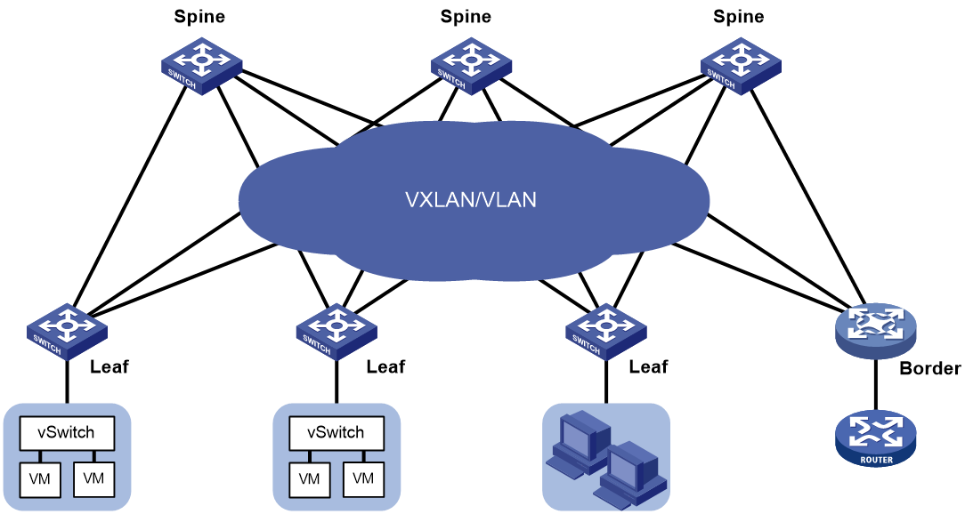
As shown in Figure 1, the following nodes exist in a 2-layer data center VCF fabric:
· Spine node—Connects to leaf nodes.
· Leaf node—Connects to servers.
· Border node—Located at the border of a VCF fabric to provide access to the external network.
Spine nodes and leaf nodes form a large Layer 2 network, which can be a VLAN, a VXLAN with centralized IP gateways, or a VXLAN with distributed IP gateways. For more information about centralized IP gateways and distributed IP gateways, see VXLAN Configuration Guide.
Figure 1 Topology for a 2-layer data center VCF fabric
Topology for a 3-layer data center VCF fabric
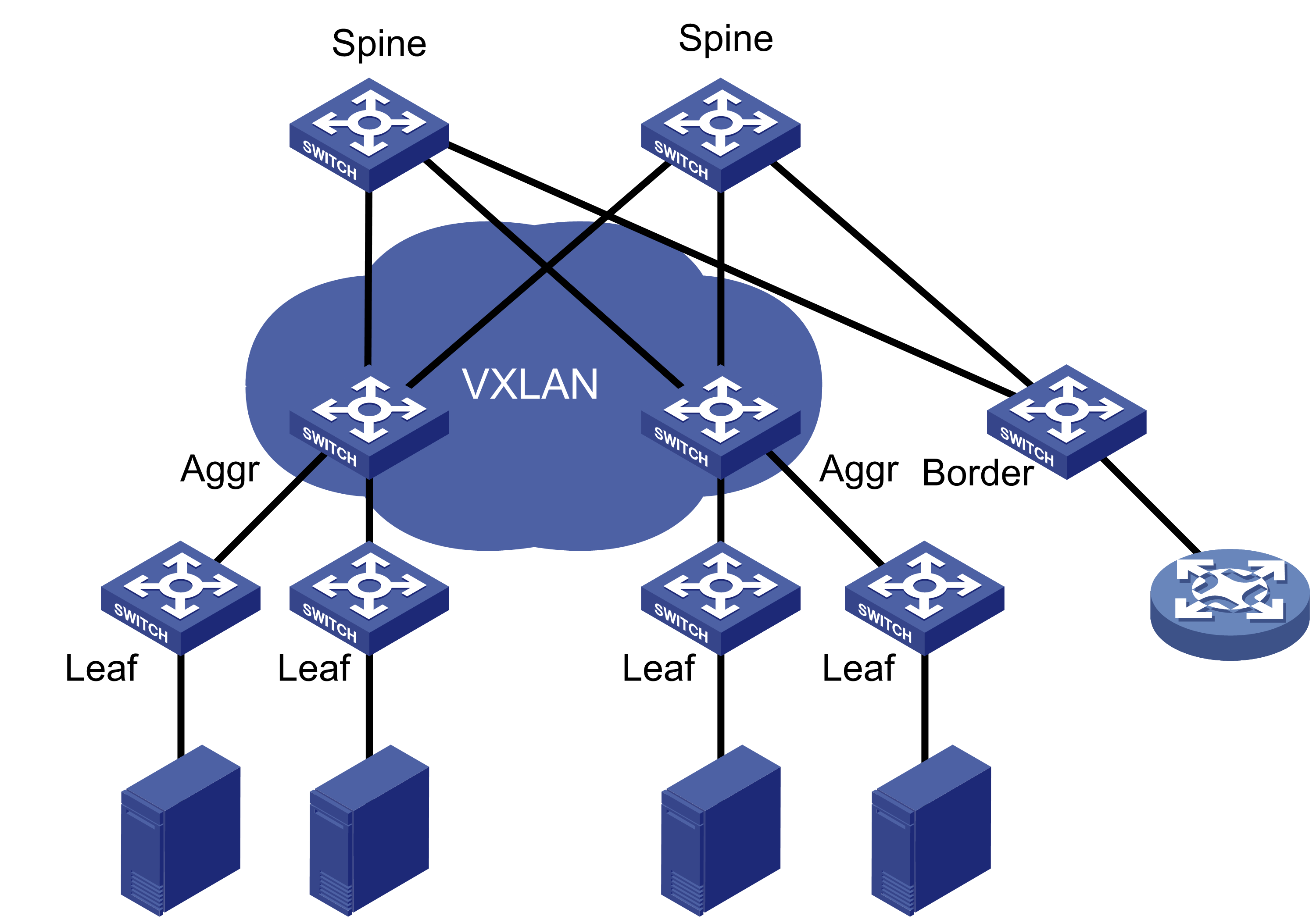
As shown in Figure 2, the following nodes exist in a 3-layer data center VCF fabric:
· Spine node—Connects to aggregate nodes.
· Aggregate node—Resides on the distribution layer and is located between leaf nodes and spine nodes.
· Leaf node—Connects to servers.
· Border node—Located at the border of a VCF fabric to provide access to the external network.
OSPF runs on the Layer 3 networks between the spine and aggregate nodes and between the aggregate and leaf nodes. VXLAN is used to set up the Layer 2 overlay network.
Figure 2 Topology for a 3-layer data center VCF fabric
Topology for a 4-layer data center VCF fabric
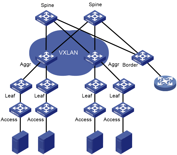
In a 4-layer data center VCF fabric, a device has one of the following roles:
· Spine node—Connects to aggregate nodes.
· Aggregate node—Located between leaf nodes and spine nodes.
· Leaf node—Located between aggregate nodes and access nodes.
· Access node—An access device, which connects to an upstream leaf node and a downstream server.
· Border node—Located at the border of a VCF fabric to provide access to the external network.
OSPF runs on the Layer 3 networks between the spine and aggregate nodes and between the aggregate and leaf nodes. VXLAN is used to set up the Layer 2 overlay network.
Figure 3 Topology for a 4-layer data center VCF fabric
VCF fabric topology for a campus network
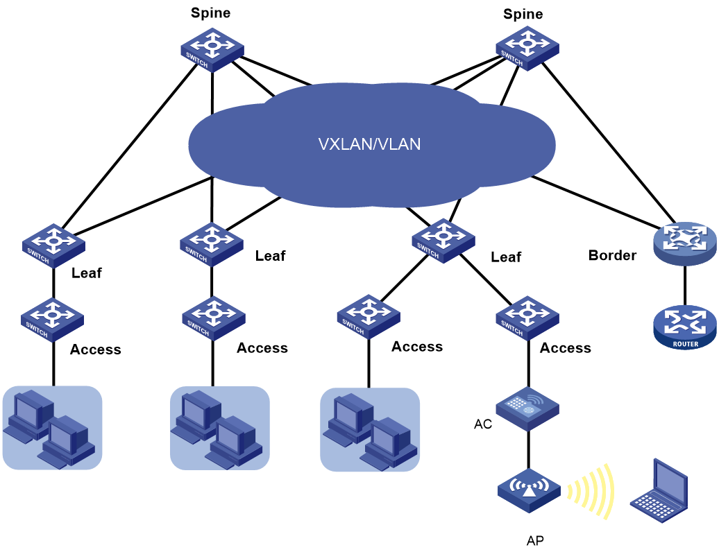
As shown in Figure 4, the following nodes exist in a campus VCF fabric:
· Spine node—Connects to leaf nodes.
· Leaf node—Connects to access nodes.
· Access node—Connects to an upstream leaf node and downstream terminal devices. Cascading of access nodes is supported.
· Border node—Located at the border of a VCF fabric to provide access to the external network.
Spine nodes and leaf nodes form a large Layer 2 network, which can be a VLAN, a VXLAN with a centralized IP gateway, or a VXLAN with distributed IP gateways. For more information about centralized IP gateways and distributed IP gateways, see VXLAN Configuration Guide.
Figure 4 VCF fabric topology for a campus network
Neutron concepts and components
Neutron is a component in OpenStack architecture. It provides networking services for VMs, manages virtual network resources (including networks, subnets, DHCP, virtual routers), and creates an isolated virtual network for each tenant. Neutron provides a unified network resource model, based on which VCF fabric is implemented.
The following are basic concepts in Neutron:
· Network—A virtual object that can be created. It provides an independent network for each tenant in a multitenant environment. A network is equivalent to a switch with virtual ports which can be dynamically created and deleted.
· Subnet—An address pool that contains a group of IP addresses. Two different subnets communicate with each other through a router.
· Port—A connection port. A router or a VM connects to a network through a port.
· Router—A virtual router that can be created and deleted. It performs routing selection and data forwarding.
Neutron has the following components:
· Neutron server—Includes the daemon process neutron-server and multiple plug-ins (neutron-*-plugin). The Neutron server provides an API and forwards the API calls to the configured plugin. The plug-in maintains configuration data and relationships between routers, networks, subnets, and ports in the Neutron database.
· Plugin agent (neutron-*-agent)—Processes data packets on virtual networks. The choice of plug-in agents depends on Neutron plug-ins. A plug-in agent interacts with the Neutron server and the configured Neutron plug-in through a message queue.
· DHCP agent (neutron-dhcp-agent)—Provides DHCP services for tenant networks.
· L3 agent (neutron-l3-agent)—Provides Layer 3 forwarding services to enable inter-tenant communication and external network access.
Neutron deployment
Neutron needs to be deployed on servers and network devices.
The following table shows Neutron deployment on a server.
|
Node |
Neutron components |
|
Controller node |
· Neutron server · Neutron DB · Message server (such as RabbitMQ server) · ML2 Driver |
|
Network node |
· neutron-openvswitch-agent · neutron-dhcp-agent |
|
Compute node |
· neutron-openvswitch-agent · LLDP |
The following table shows Neutron deployments on a network device.
|
Network type |
Network device |
Neutron components |
|
Centralized gateway deployment |
Spine |
· neutron-l2-agent · neutron-l3-agent |
|
Leaf |
neutron-l2-agent |
|
|
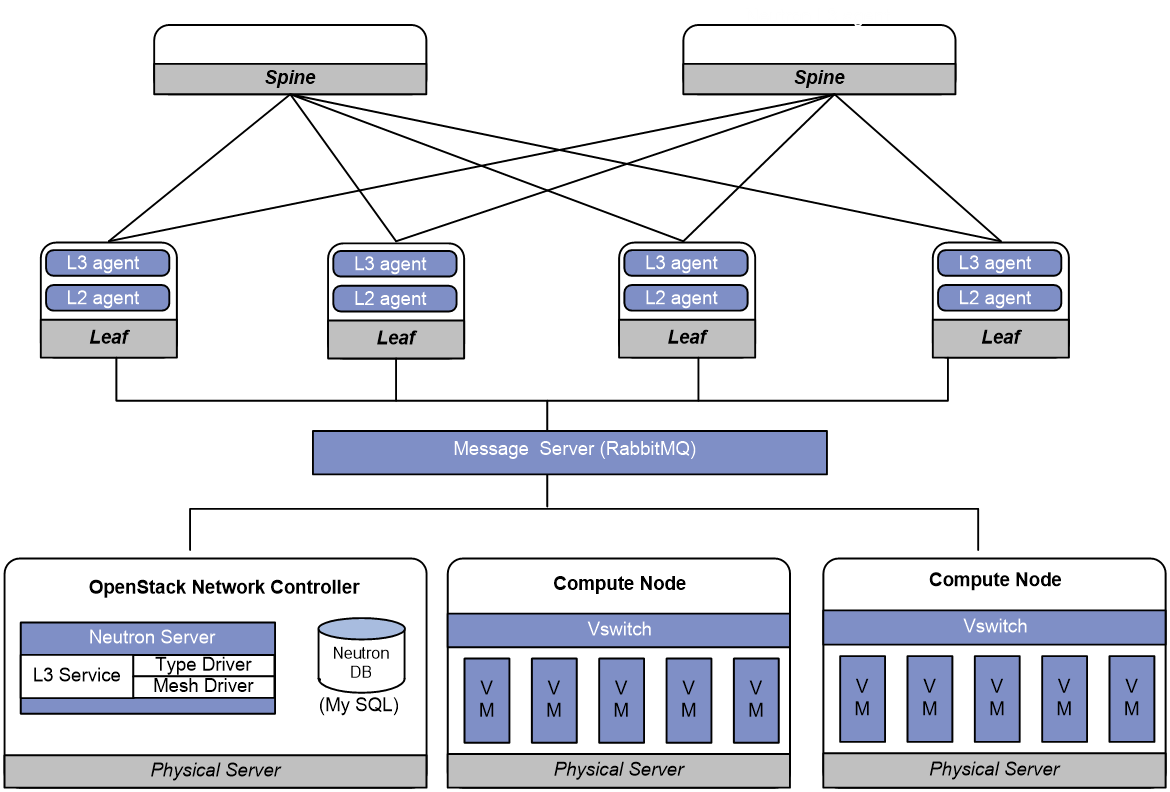
Distributed gateway deployment |
Spine |
N/A |
|
Leaf |
· neutron-l2-agent · neutron-l3-agent |
Figure 5 Example of Neutron deployment for centralized gateway deployment
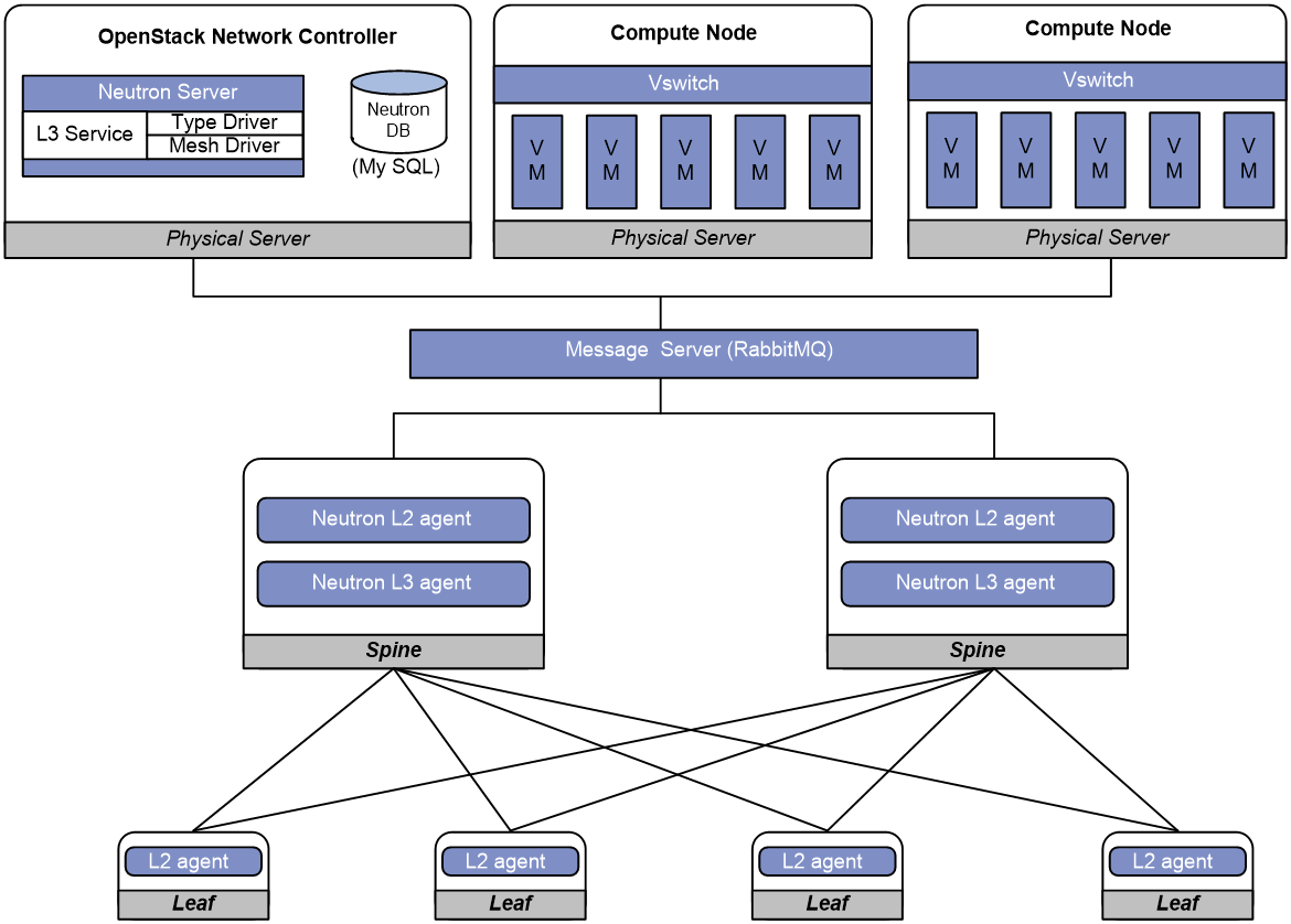
Figure 6 Example of Neutron deployment for distributed gateway deployment
Restrictions and guidelines: VCF fabric configuration
All VCF fabric commands are supported only on the default MDC.
Automated VCF fabric provisioning and deployment
VCF provides the following features to ease deployment:
· Automatic topology discovery.
· Automated underlay network provisioning.
· Automated overlay network deployment.
Two IRF member devices in an IRF fabric use the following rules to elect the IRF master during automated VCF fabric deployment:
· If the uptime of both devices is shorter than two hours, the device with the higher bridge MAC address becomes the IRF master.
· If the uptime of one device is equal to or longer than two hours, that device becomes the IRF master.
· If the uptime of both devices are equal to or longer than two hours, the IRF fabric cannot be set up. You must manually reboot one of the member devices. The rebooted device will become the IRF subordinate.
If the IRF member ID of a device is not 1, the IRF master might reboot during automatic IRF fabric setup.
Topology discovery
In a VCF fabric, each device uses LLDP to collect local topology information from directly-connected peer devices. The local topology information includes connection interfaces, roles, MAC addresses, and management interface addresses of the peer devices.
If multiple spine nodes exist in an IPv4 VCF fabric, a master spine node is specified to collect the topology for the entire network. In an IPv6 VCF fabric, the controller collects the topology automatically.
Automated underlay network provisioning
An underlay network is a physical Layer 3 network. An overlay network is a virtual network built on top of the underlay network. The main stream overlay technology is VXLAN. For more information about VXLAN, see VXLAN Configuration Guide.
Automated underlay network provisioning sets up a Layer 3 underlay network for users. It is implemented by automatically executing configurations (such as IRF configuration and Layer 3 reachability configurations) in user-defined template files.
Provisioning prerequisites
Before you start automated underlay network provisioning, complete the following tasks:
1. Finish the underlay network planning (such as IP address assignment, reliability design, and routing deployment) based on user requirements.
¡ In a data center network, the device obtains an IP address through a management Ethernet interface after starting up without loading configuration.
¡ In a campus network, the device obtains an IP address through VLAN-interface 1 after starting up without loading configuration.
2. Install and configure the Director server.
This step is required if you want to use the Director server to automatically create template files.
3. Configure the DHCP server, the TFTP server, and the NTP server.
4. Upload the template files to the TFTP server.
Template files for different roles in the VCF fabric are the basis of automatic provisioning. A template file name ends in .template. The Director server automatically creates template files for different device roles in the network topology. The following are available template types:
¡ Template for a leaf node in a VLAN.
¡ Template for a leaf node in a VXLAN with a centralized gateway.
¡ Template for a leaf node in a VXLAN with distributed gateways.
¡ Template for a spine node in a VLAN.
¡ Template for a spine node in a VXLAN with a centralized gateway.
¡ Template for a spine node in a VXLAN with distributed gateways.
Process of automated underlay network provisioning
The device finishes automated underlay network provisioning as follows:
1. Starts up with the initial configuration.
2. Obtains an IP address, the IP address of the TFTP server, and a template file name from the DHCP server.
3. Downloads tag file device_tag.csv from the TFTP server and compares its SN code with the SN code in the tag file.
¡ If the two SN codes are the same, the device uses the device role and system description in the tag file.
¡ If the two SN codes are different, the device does not use the device role and system description.
4. Determines the name of the template file to download based on the following information:
¡ The device role in the tag file or the default device role.
¡ The template file name obtained from the DHCP server.
For example, template file dist_leaf.template is for a leaf node in a VXLAN network with distributed IP gateways.
5. Downloads the template file from the TFTP server.
6. Parses the template file and performs the following operations:
¡ Deploys static configurations that are independent from the VCF fabric topology.
¡ Deploys dynamic configurations according to the VCF fabric topology.
- In a data center network, the device usually uses a management Ethernet interface to connect to the fabric management network. Only links between leaf nodes and servers are automatically aggregated.
- In a campus network, the device uses VLAN-interface 1 to connect to the fabric management network. Links between two access nodes cascaded through GigabitEthernet interfaces and links between leaf nodes and access nodes are automatically aggregated. For links between spine nodes and leaf nodes, the trunk permit vlan command is automatically executed.
- In a campus network where multiple leaf nodes that have an access node attached form an IRF fabric, make sure only one link exists between each leaf node and its connected access node.
|
|
NOTE: · On a data center network, if the template file contains software version information, the device first compares the software version with the current software version. If the two versions are inconsistent, the device downloads the new software version to perform software upgrade. After restarting, the device executes the configurations in the template file. · After all configurations in the template file are executed, the device does not save the configurations automatically if the template file does not contain IRF configuration. In this condition, you can use the save command to save the configurations to a configuration file. · For two directly connected devices with the same role to form an IRF fabric automatically, connect their IRF physical interfaces before automated underlay network provisioning. |
Template file
A template file contains the following:
· System-predefined variables—The variable names cannot be edited, and the variable values are set by the VCF topology discovery feature.
· User-defined variables—The variable names and values are defined by the user. These variables include the username and password used to establish a connection with the Neutron server, network type, and so on. The following are examples of user-defined variables:
¡ IPv4:
#USERDEF
_underlayIPRange = 10.100.0.0/16
_master_spine_mac = 1122-3344-5566
_username = aaa
_password = hello12345
_rbacUserRole = network-admin
_neutron_username = openstack
_neutron_password = 12345678
_neutron_ip = 172.16.1.136
_loghost_ip = 172.16.1.136
_network_type = centralized-vxlan
¡ IPv6:
#USERDEF
_username = aaa
_password = hello12345
_rbacUserRole = network-admin
_loghost_ip = 200:0:0:0:0:0:0:210
_network_type = distributed-vxlan
_OOB = True
_lagg_enable = false
_lagg_mode = dynamic
……
· Static configurations—Static configurations are independent from the VCF fabric topology and can be directly executed. The following are examples of static configurations:
#STATICCFG
#
clock timezone beijing add 08:00:00
#
lldp global enable
#
stp global enable
#
· Dynamic configurations—Dynamic configurations are dependent on the VCF fabric topology. The device first obtains the topology information and then executes dynamic configurations. The following are examples of dynamic configurations:
#
interface $$_underlayIntfDown
port link-mode route
ip address unnumbered interface LoopBack0
ospf 1 area 0.0.0.0
ospf network-type p2p
lldp management-address arp-learning
lldp tlv-enable basic-tlv management-address-tlv interface LoopBack0
#
Automated overlay network deployment
Automated overlay network deployment covers VXLAN deployment and EVPN deployment.
Automated overlay network deployment is mainly implemented through the following features of Neutron:
· Layer 2 agent (L2 agent)—Responds to OpenStack events such as network creation, subnet creation, and port creation. It deploys Layer 2 networking to provide Layer 2 connectivity within a virtual network and Layer 2 isolation between different virtual networks.
· Layer 3 agent (L3 agent)—Responds to OpenStack events such as virtual router creation, interface creation, and gateway configuration. It deploys the IP gateways to provide Layer 3 forwarding services for VMs.
Automated overlay network deployment is not supported on aggregate or access nodes.
VCF does not support automating IPv6 overlay networks.
For the device to correctly communicate with the Neutron server through the RabbitMQ server, you need to configure the RabbitMQ server parameters. The parameters include the IP address of the RabbitMQ server, the username and password to log in to the RabbitMQ server, and the listening port.
Configuration restrictions and guidelines
Typically, the device completes both automated underlay network provisioning and automated overlay network deployment by downloading and executing the template file. You do not need to manually configure the device by using commands. If the device needs to complete only automated overlay network deployment, you can use related commands in "Enabling VCF fabric topology discovery" and "Configuring automated overlay network deployment." No template file is required.
VCF fabric configuration task list
|
Tasks at a glance |
|
(Required.) Enabling VCF fabric topology discovery |
|
(Optional.) Configuring automated underlay network provisioning |
|
(Optional.) Configuring automated overlay network deployment |
Enabling VCF fabric topology discovery
Configuration restrictions and guidelines
VCF fabric topology discovery can be automatically enabled by executing configurations in the template file or be manually enabled at the CLI. The device uses LLDP to collect topology data of directly-connected devices. Make sure you have enabled LLDP on the device before you manually enable VCF fabric topology discovery.
Configuration procedure
|
Step |
Command |
Remarks |
|
1. Enter system view. |
system-view |
N/A |
|
2. Enable LLDP globally. |
lldp global enable |
By default, LLDP is disabled globally. |
|
3. Enable VCF fabric topology discovery. |
vcf-fabric topology enable |
By default, VCF fabric topology discovery is disabled. |
Configuring automated underlay network provisioning
Configuration restrictions and guidelines
When you configure automated underlay network provisioning, follow these restrictions and guidelines:
· Automated underlay network configuration can be automatically completed after the device starts up. If you need to change the automated underlay network provision on a running device, you can download the new template file through TFTP. Then, execute the vcf-fabric underlay autoconfigure command to manually specify the template file on the device.
· As a best practice, do not modify the network type or the device role while the device is running. If it is necessary to do so, make sure you understand the impacts on the network and services.
· If you change the role of the device, the new role takes effect after the device restarts up.
· User-defined MDCs do not have a role by default. You can use the vcf-fabric role { access | leaf | spine } command to specify the role for the MDCs. Automated underlay network provisioning is not supported by user-defined MDCs. The Director server can identify the role of user-defined MDCs in the VCF fabric and deploy configuration to the MDCs through NETCONF.
· To use devices that have come online after automated deployment to form an IRF fabric, make sure all member devices in the IRF fabric have the same VCF fabric role.
· Do not perform link migration when devices in the VCF fabric are in the process of coming online or powering down after the automated VCF fabric deployment finishes. A violation might cause link-related configuration fails to update.
· After automated underlay network deployment starts, you cannot use the CLI commands to modify the configuration. A violation might cause automated deployment failure. If you want to modify the configuration, first cancel or pause automated deployment. Additionally, do not start automated deployment after the modification. To cancel automated deployment, use the undo vcf-fabric underlay autoconfigure command. To pause automated deployment, use the vcf-fabric underlay pause command.
· The underlay network can be an IPv4 or IPv6 network.
Configuration procedure
|
Step |
Command |
Remarks |
|
1. Enter system view. |
system-view |
N/A |
|
2. (Optional.) Specify the role of the device in the VCF fabric. |
vcf-fabric role { access | aggr | leaf | spine } |
By default, the role of the device in the VCF fabric is spine. |
|
3. Specify the template file for automated underlay network provisioning. |
vcf-fabric underlay autoconfigure template |
By default, no template file is specified for automated underlay network provisioning. |
|
4. (Optional.) Pause automated underlay network provisioning. |
vcf-fabric underlay pause |
By default, automated underlay network provisioning is not paused. |
|
5. (Optional.) Configure the device as a master spine node. |
vcf-fabric spine-role master |
By default, the device is not a master spine node. If multiple spine nodes exist in an IPv4 VCF fabric, a master spine node is specified to collect the topology for the entire network. In an IPv6 VCF fabric, the controller collects the topology automatically. |
|
1. Set the NETCONF username: 2. Set the NETCONF password: |
By default, the device uses the NETCONF username and password defined in the template file for automated VCF fabric deployment. |
|
|
3. (Optional.) Enable Neutron and enter Neutron view. |
neutron |
By default, Neutron is disabled. |
|
4. (Optional.) Specify the network type. |
network-type { centralized-vxlan | distributed-vxlan | vlan } |
By default, the network type is VLAN. |
Configuring automated overlay network deployment
Configuration restrictions and guidelines
When you configure automated overlay network deployment, follow these restrictions and guidelines:
· If the network type is VLAN or VXLAN with a centralized IP gateway, perform this task on both the spine node and the leaf nodes.
· If the network type is VXLAN with distributed IP gateways, perform this task on all leaf nodes.
· Make sure the RabbitMQ server settings on the device are the same as those on the controller node. If the durable attribute of RabbitMQ queues is set on the Neutron server, you must enable creation of RabbitMQ durable queues on the device so that RabbitMQ queues can be correctly created.
· When you set the RabbitMQ server parameters or remove the settings, make sure the routes between the device and the RabbitMQ servers are reachable. Otherwise, the CLI does not respond until the TCP connections between the device and the RabbitMQ servers are terminated.
· Multiple virtual hosts might exist on a RabbitMQ server. Each virtual host can independently provide RabbitMQ services for the device. For the device to correctly communicate with the Neutron server, specify the same virtual host on the device and the Neutron server.
· As a best practice, do not perform any of the following tasks while the device is communicating with a RabbitMQ server:
¡ Change the source IPv4 address for the device to communicate with RabbitMQ servers.
¡ Bring up or shut down a port connected to a RabbitMQ server.
If you do so, it will take the CLI a long time to respond to the l2agent enable, undo l2agent enable, l3agent enable, or undo l3agent enable command.
Configuration procedure
|
Step |
Command |
Remarks |
|
1. Enter system view. |
system-view |
N/A |
|
2. Enable Neutron and enter Neutron view. |
neutron |
By default, Neutron is disabled. |
|
3. Specify the IPv4 address, port number, and MPLS L3VPN instance of a RabbitMQ server. |
rabbit host ip ipv4-address [ port port-number ] [ vpn-instance vpn-instance-name ] |
By default, no IPv4 address or MPLS L3VPN instance of a RabbitMQ server is specified, and the port number of a RabbitMQ server is 5672. |
|
4. Specify the source IPv4 address for the device to communicate with RabbitMQ servers. |
rabbit source-ip ipv4-address [ vpn-instance vpn-instance-name ] |
By default, no source IPv4 address is specified for the device to communicate with RabbitMQ servers. The device automatically selects a source IPv4 address through the routing protocol to communicate with RabbitMQ servers. |
|
5. (Optional.) Enable creation of RabbitMQ durable queues. |
rabbit durable-queue enable |
By default, RabbitMQ non-durable queues are created. |
|
6. Configure the username used by the device to establish a connection with the RabbitMQ server. |
rabbit user username |
By default, the device uses username guest to establish a connection with the RabbitMQ server. |
|
7. Configure the password used by the device to establish a connection with the RabbitMQ server. |
rabbit password { cipher | plain } string |
By default, the device uses plaintext password guest to establish a connection with the RabbitMQ server. |
|
8. Specify a virtual host to provide RabbitMQ services. |
rabbit virtual-host hostname |
By default, the virtual host / provides RabbitMQ services for the device. |
|
9. Specify the username and password used by the device to deploy configurations through RESTful. |
restful user username password { cipher | plain } password |
By default, no username or password is configured for the device to deploy configurations through RESTful. |
|
10. (Optional.) Enable the Layer 2 agent. |
l2agent enable |
By default, the Layer 2 agent is disabled. |
|
11. (Optional.) Enable the Layer 3 agent. |
l3agent enable |
By default, the Layer 3 agent is disabled. |
|
12. (Optional.) Configure export targets for a tenant VPN instance. |
vpn-target target export-extcommunity |
By default, no export targets are configured for a tenant VPN instance. |
|
13. (Optional.) Configure import route targets for a tenant VPN instance. |
vpn-target target import-extcommunity |
By default, no import route targets are configured for a tenant VPN instance. |
|
14. (Optional.) Specify the IPv4 address of the border gateway. |
gateway ip ipv4-address |
By default, the IPv4 address of the border gateway is not specified. |
|
15. (Optional.) Configure the device as a border node. |
border enable |
By default, the device is not a border node. |
|
16. (Optional.) Enable local proxy ARP. |
proxy-arp enable |
By default, local proxy ARP is disabled. |
|
17. (Optional.) Configure the MAC address of VSI interfaces. |
vsi-mac mac-address |
By default, no MAC address is configured for VSI interfaces. |
Displaying and maintaining VCF fabric
Execute display commands in any view.
|
Task |
Command |
|
Display the role of the device in the VCF fabric. |
display vcf-fabric role |
|
Display VCF fabric topology information. |
display vcf-fabric topology |
|
Display information about automated underlay network provisioning. |
display vcf-fabric underlay autoconfigure |
|
Display the supported version and the current version of the template file for automated VCF fabric provisioning. |
display vcf-fabric underlay template-version |