- Table of Contents
- Related Documents
-
| Title | Size | Download |
|---|---|---|
| 04-EVPN VPWS configuration | 1.17 MB |
Contents
Remote connection establishment
Inter-AS communication of EVPN VPWS
LDP or static PW ACs for EVPN PWs
Restrictions: Hardware compatibility with VXLAN VPWS
Configuring a remote connection
Configuring a Layer 3 interface with Ethernet or VLAN encapsulation
Configuring an Ethernet service instance on an interface
Configuring EVPN route advertisement
Restrictions and guidelines for EVPN route advertisement configuration
Enabling BGP to advertise BGP EVPN routes
Enabling the device to advertise MPLS-encapsulated BGP EVPN routes
Configuring attributes of BGP EVPN routes
Configuring optimal BGP EVPN route selection
Configuring BGP route reflection
Advertising BGP RPKI validation state to a peer or peer group
Configuring BGP soft-reset by saving route updates
Mapping an AC to a cross-connect
About mapping an AC to a cross-connect
Restrictions and guidelines for mapping an AC to a cross-connect
Mapping a Layer 3 interface to a cross-connect
Mapping an Ethernet service instance to a cross-connect
Configuring EVPN VPWS multihoming
Restrictions and guidelines for EVPN VPWS multihoming
Assigning an ESI to an interface
Configuring the DF election algorithm
Setting the redundancy mode on an interface
Enabling fast DF/BDF switchover
Disabling advertisement of EVPN multihoming routes
Enabling the device to monitor the BGP peer status of another local edge device
Enabling cross-connects to ignore the state of ACs
Configuring LDP or static PWs as ACs for EVPN PWs
About LDP or static PW AC configuration for EVPN PWs
Restrictions and guidelines for LDP or static PW AC configuration for EVPN PWs
Prerequisites for LDP or static PW AC configuration for EVPN PWs
Configuring an LDP PW as an AC for an EVPN PW
Configuring a static PW as an AC for an EVPN PW
Testing the connectivity of an EVPN PW
Prerequisites for EVPN PW connectivity test
Tracing the path to a PW destination
Display and maintenance commands for EVPN VPWS
EVPN VPWS configuration examples
Example: Configuring a remote connection between singlehomed sites
Example: Configuring EVPN VPWS multihoming
Example: Configuring PW concatenation
Example: Configuring inter-AS option A
Example: Configuring inter-AS option B
Example: Configuring inter-AS option C
Example: Configuring FRR for EVPN VPWS
Example: Configuring LDP PWs as ACs for EVPN PWs
Configuring EVPN VPWS
About EVPN VPWS
EVPN Virtual Private Wire Service (VPWS) is a Layer 2 VPN technology that uses MP-BGP for BGP EVPN route advertisement in the control plane and MPLS for forwarding in the data plane. EVPN VPWS provides point-to-point forwarding services for users by using ACs and PWs associated with cross-connects without MAC address table lookup.
EVPN VPWS network model
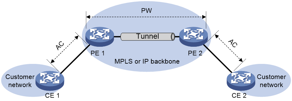
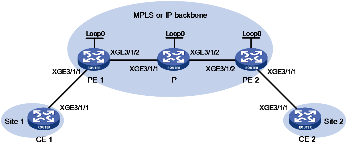
As shown in Figure 1, an EVPN VPWS network contains the following devices:
· Customer edge (CE)—Customer device directly connected to the service provider network.
· Provider edge (PE)—Service provider device connected to CEs. PEs provide access to the EVPN VPWS network and forward traffic between customer network sites by using public tunnels.
A PE uses ACs, PWs, tunnels, and cross-connects to provide EVPN VPWS services.
· Attachment circuit (AC)—A physical or virtual link between a CE and a PE.
· Pseudowire (PW)—A virtual bidirectional connection between two PEs. A PW comprises a pair of virtual connections in opposite directions.
· Public tunnel—A connection that carries one or more PWs across the MPLS or IP backbone. A public tunnel can be an LSP, GRE tunnel, or MPLS TE tunnel.
· Cross-connect—A connection formed by two physical or virtual circuits such as ACs and PWs. It switches packets between the two physical or virtual circuits. Cross-connects include AC to AC cross-connect and AC to PW cross-connect.
Remote connection establishment
To set up a remote EVPN VPWS connection:
1. Set up a public tunnel to carry one or more PWs between PEs.
2. Set up a PW to connect customer networks.
3. Set up an AC between a PE and a CE.
4. Bind the AC to the PW.
After the PE receives packets from the AC, it adds the PW label into the packets and sends the packets to the peer PE through the public tunnel.
After the peer PE receives the packets from the public tunnel, it removes the PW label of the packets and forwards the packets to the AC bound to the PW.
Public tunnel establishment
The public tunnel can be an LSP, MPLS TE, or GRE tunnel.
If multiple public tunnels are set up between two PEs, you can configure a tunnel policy to control tunnel selection. For more information about tunnel policies, see MPLS Configuration Guide.
If a PW is established over an LSP or MPLS TE tunnel, packets on the PW have two labels. The outer label is the public LSP or MPLS TE tunnel label that MPLS uses to forward the packet to the peer PE. The inner label is the PW label that the peer PE uses to forward the packet to the destination CE.
PW establishment
A PW is established between two PEs based on the local and remote service IDs configured on the PEs. In an EVPN VPWS network, each PE advertises its local service ID through Ethernet auto-discovery routes and compares received local service IDs with its remote service ID. A PE establishes a unidirectional virtual connection to a peer If the local service ID advertised by the peer matches the remote service ID. PW establishment is finished when two virtual connections in opposite directions are established between two PEs.
AC establishment
For EVPN VPWS, an AC is associated with a cross-connect and can be a Layer 3 Ethernet interface, Layer 3 Ethernet subinterface, or Ethernet service instance on a PE. An Ethernet service instance is created on a Layer 2 Ethernet interface to match incoming customer traffic on that interface based on a frame match criterion.
AC-to-PW bindings
For PEs to forward packets between an AC and a PW, bind the AC to the PW.
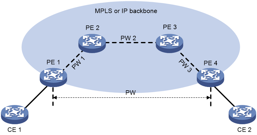
EVPN VPWS multihoming
About this task
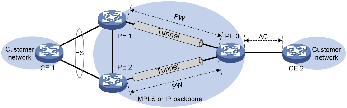
As shown in Figure 2, EVPN VPWS supports deploying multiple PEs at a site for redundancy and high availability. On the redundant PEs, Ethernet links connected to the site form an ES that is uniquely identified by an ESI. EVPN VPWS supports only dualhoming.
Figure 2 EVPN VPWS multihoming
Redundancy mode
The device supports single-active redundancy mode and all-active redundancy mode of EVPN VPWS multihoming.
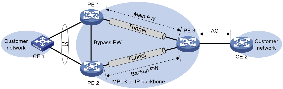
· Single-active mode—This mode allows one of the redundant PWs to forward traffic, as shown in Figure 3. When the main PW becomes unavailable because of device failure or link failure, traffic is switched to the backup PW for forwarding. The redundant PEs elect the main PW as described in "About DF election". To ensure quick failover, EAA CLI-defined monitor policies and Track are configured on the CE-facing physical interface and the transport-facing physical interface used for establishing the main PW on PE 1. When the underlay network is disconnected, PE 1 shuts down the CE-facing physical interface so all traffic of CE 1 is forwarded through PE 2. For more information about EAA, see Network Management and Monitoring Configuration Guide.
· All-active mode—This mode allows all redundant PWs to a multihomed site to load share traffic. To ensure quick failover, EAA CLI-defined monitor policies and Track are configured on the CE-facing physical interface and the transport-facing physical interface used for establishing a PW on each redundant PE.
About DF election
In single-active mode, a DF is elected from the redundant PEs to determine the main PW. PEs that fail the election are assigned the BDF role. The PWs on BDFs do not forward traffic.
Redundant PEs at a site send Ethernet segment routes to one another to advertise ES and PE IP mappings. A PE accepts the Ethernet segment routes only when it is configured with an ESI. Then, the PEs select a DF based on the ES and PE IP mappings. DF election can be performed by using a VLAN tag-based algorithm or preference-based algorithm.
VLAN tag-based DF election
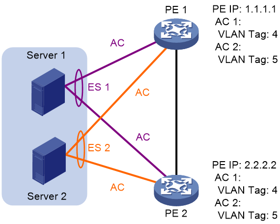
PEs select a DF for each AC based on the VLAN tag and PE IP address as follows:
1. Arrange source IP addresses in Ethernet segment routes with the same ESI in ascending order and assign a sequence number to each IP address, starting from 0.
2. Divide the lowest VLAN ID permitted on an AC by the number of the redundant PEs, and match the reminder to the sequence numbers of IP addresses.
3. Assign the DF role to the PE that uses the IP address with the matching sequence number.
The following uses PE 1 and PE 2 in Figure 5 as an example to explain the DF election procedure:
1. PE 1 and PE 2 send Ethernet segment routes to each other.
2. The PEs assign sequence numbers 0 and 1 to IP addresses 1.1.1.1 and 2.2.2.2 in the Ethernet segment routes, respectively.
3. The PEs divide 4 (the lowest VLAN ID permitted by the ACs) by 2 (the number of redundant PEs), and match the reminder 0 to the sequence numbers of the IP addresses.
4. The DF role is assigned to PE 1 at 1.1.1.1.
Figure 5 VLAN tag-based DF election
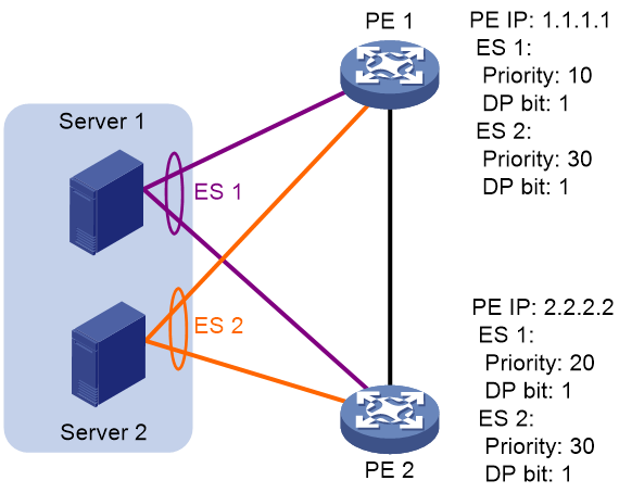
Preference-based DF election
PEs select a DF for each ES based on the DF election preference, the Don't Preempt Me (DP) bit in Ethernet segment routes, and PE IP address. The DP bit can be set to one of the following values:
· 1—DF preemption is disabled. A DF retains its role when a new DF is elected.
· 0—DF preemption is enabled.
Preference-based DF election uses the following rules to select a DF for an ES:
· The PE with higher preference becomes the DF.
· If two PEs have the same preference, the PE with the DP bit set to 1 becomes the DF. If both of the PEs have the DP bit set to 1, the PE with a lower IP address becomes the DF.
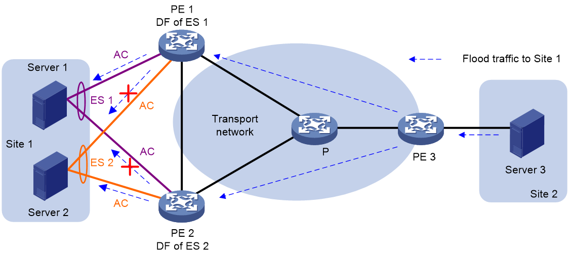
As shown in Figure 6, PE 2 is the DF for ES 1, and PE 1 is the DF for ES 2.
Figure 6 Preference-based DF election
FRR for EVPN VPWS
About FRR
Fast reroute (FRR) helps reduce the traffic loss caused by AC or PW failure on an EVPN VPWS network. FRR includes local FRR and remote FRR.
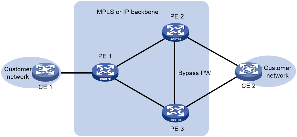
Local FRR
Local FRR enables two PEs at a multihomed EVPN VPWS network site to set up a bypass PW between them.
As shown in Figure 7, CE 2 is dualhomed to PE 2 and PE 3. When the AC on PE 2 fails, PE 2 advertises the local unreachable event to PE 1 and PE 3 for PE 1 to switch traffic to the PW to PE 3. In this situation, PE 3 drops the packets that PE 1 sends before it is notified of the local unreachable event. To resolve this issue, enable local FRR on PE 2 and PE 3. When receiving packets from PE 1 after PE 2's AC fails, PE 2 forwards the packets to PE 3 over the bypass PW to prevent traffic loss.
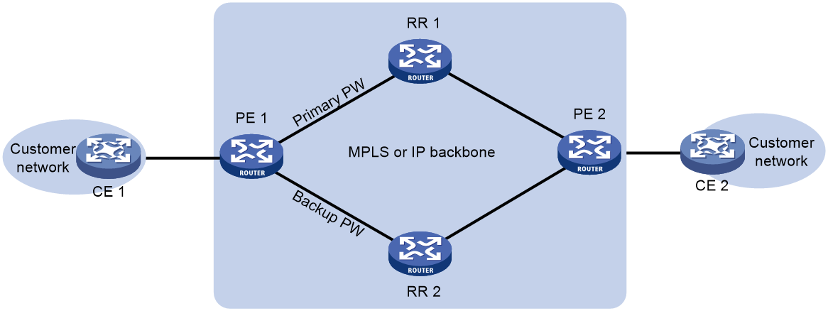
Remote FRR
Remote FRR enables two PEs on an EVPN VPWS network to set up a primary PW and a backup PW between them to ensure high availability. This feature is applicable to both multihoming and singlehoming scenarios.
As shown in Figure 8, PE 1 and PE 2 are connected by RR 1 and RR 2. The RRs change the next hop attribute of routes and reassign MPLS labels to them based on routing policies when reflecting the routes. PE 1 and PE 2 select only RR 1 or RR 2 when establishing a PW. For high availability, you can enable remote FRR on PE 1 for it to set up PWs to both RRs. PE 1 uses the primary PW to forward traffic as long as it is available. When the primary PW fails, PE 1 switches traffic to the backup PW. For more information about optimal route selection on PE 1, see BGP configuration in Layer 3—IP Routing Configuration Guide.
Control word
The control word field is between the MPLS label stack and the Layer 2 data. It carries control information for the Layer 2 frame, for example, the sequence number.
The control word feature has the following functions:
· Avoids fragment disorder. In multipath forwarding, fragments received might be disordered. The control word feature reorders the fragments according to the sequence number carried in the control word field.
· Identifies the original payload length for packets that include padding.
The control word field is optional for EVPN PWs. You can configure whether to carry the control word field in packets sent on the PW. If you enable the control word feature on both PEs, packets transmitted on the PW carry the control word field. Otherwise, the packets do not carry the control word field.
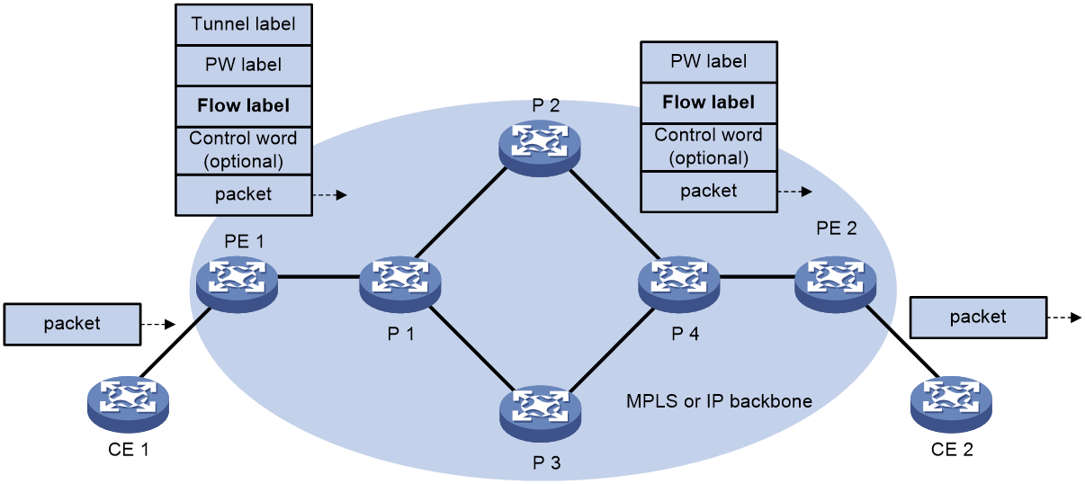
L2VPN flow label
Packets carrying different types of traffic might be transmitted through the same PW and encapsulated with the same PW label. The P devices forward the traffic flows of a PW over the same path even if Equal Cost Multiple Paths (ECMPs) exist.
The L2VPN flow label feature can enable a P device to perform load sharing on packets based on the flow types.
After you configure this feature, the P and PE devices process packets as follows:
· When the ingress PE encapsulates a packet, it adds a flow label before it adds a PW label, as shown in Figure 9.
The ingress PE adds different flow labels for packets of different traffic types.
· The P devices perform load sharing on packets based on the flow labels.
· The egress PE removes both the PW and flow labels from a packet before forwarding the packet.
Figure 9 L2VPN flow label feature
You can enable the flow label sending, receiving, or both sending and receiving capabilities on a PE.
· The sending capability enables a PE to send packets with flow labels. The PE adds a flow label before it adds a PW label to a packet during PW encapsulation.
· The receiving capability enables a PE to identify the flow label in a received packet and removes the flow label before forwarding the packet.
For two PEs to successfully negotiate the flow label capabilities, make sure one end has the sending capability and the other end has the receiving capability.
For EVPN VPWS PWs, you must manually configure flow label capabilities for the local and remote PEs.
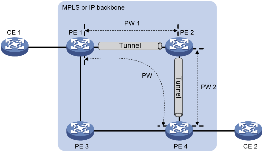
PW concatenation
As shown in Figure 10, EVPN VPWS supports concatenating two or more PWs into one PW. PW concatenation allows two PEs that do not have an end-to-end public tunnel between them to communicate. An intermediate PE forwards packets between two concatenated PWs as follows:
1. Removes the tunnel identifier and PW label from the packets received on one PW.
2. Encapsulates the packets with the label of another PW and forwards them through the public tunnel that conveys this PW.
Two PWs are concatenated by creating them on the same cross-connect. For example, to concatenate PW 1 and PW 2 in Figure 10, create them on the same cross-connect on PE 2.
PW concatenation includes intra-AS PW concatenation and inter-AS PW concatenation.
· Intra-AS PW concatenation—Concatenates PWs within an AS. As shown in Figure 11, all PEs are in the same AS, and no end-to-end public tunnel exists between PE 1 and PE 4. By concatenating PW 1 and PW 2, you can enable PE 1 and PE 4 to communicate through the existing public tunnels instead of creating a new one.
Figure 11 Intra-AS PW concatenation
· Inter-AS PW concatenation—Concatenates PWs in different ASs. For more information, see "Inter-AS option B."
Inter-AS communication of EVPN VPWS
In an inter-AS networking scenario, multiple sites of an EVPN VPWS network are connected to multiple ISPs in different ASs, or to multiple ASs of an ISP.
EVPN VPWS provides the following inter-AS communication solutions:
· Inter-AS option A—Associates the AC between ASBRs with each EVPN PW established between a PE and ASBR pair.
· Inter-AS option B—Establishes an EVPN PW between ASBRs and concatenates it with the EVPN PWs established between PE and ASBR pairs.
· Inter-AS option C—Establishes an EVPN PW between PEs in different ASs through a multihop MP-EGBP session.
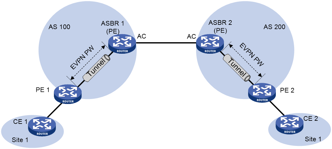
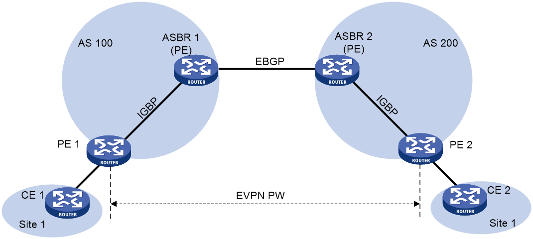
Inter-AS option A
As shown in Figure 12, in this solution, PEs of two ASs are directly connected, and each PE is also the ASBR of its AS. Each PE treats the other as a CE and associates its EVPN PW with the interface facing the peer PE for inter-AS communication.
This solution features simple implementation. You need to configure only EVPN PW and AC associations for each site on the PEs that act as ASBRs. However, the management workload increases if more sites are attached to the ASBRs.
Figure 12 Inter-AS option A network model
Inter-AS option B
As shown in Figure 13, in this solution, an EVPN PW is established between the ASBRs for inter-AS communication. The ASBRs uses MP-EBGP to exchange BGP EVPN routes to establish the EVPN PW. The PE and the ASBR in each AS use MP-IBGP to establish an EVPN PW. The EVPN PWs between the ASBRs and between each PE and ASBR pair are concatenated to forward inter-AS traffic.
This solution provides better scalability than inter-AS option A. To use this solution, you need to configure PW concatenation for each pair of sites.
Figure 13 Inter-AS option B network model
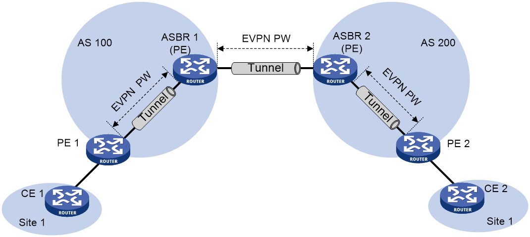
Inter-AS option C
As shown in Figure 14, in this solution, PEs in different ASs establish a multihop MP-EGBP session to exchange BGP EVPN routes and create an EVPN PW. Each PE must have a route to the peer PE and a label for the route so that the inter-AS public tunnel can be set up between the PEs. Inter-AS option C sets up a public tunnel by using the following methods:
· A label distribution protocol within the AS, for example, LDP.
· Labeled IPv4 unicast route advertisement by ASBRs through BGP.
Labeled IPv4 unicast route advertisement refers to the process of assigning MPLS labels to IPv4 unicast routes and advertising IPv4 unicast routes and their labels.
Figure 14 Inter-AS option C network model
The following is the process for setting up a public tunnel between PE 1 and PE 2 in Figure 14:
1. Within AS 100, the public tunnel from ASBR 1 to PE 1 is set up by using a label distribution protocol, for example, LDP.
Assume that the outgoing label for the public tunnel on ASBR 1 is L1.
2. ASBR 1 advertises labeled IPv4 unicast routes to ASBR 2 through EBGP.
The route destined for PE 1 and the label (L2) assigned by ASBR 1 to the route are advertised from ASBR 1 to ASBR 2. The next hop of the route is ASBR 1. The public tunnel from ASBR 2 to ASBR 1 is set up. The incoming label for the public tunnel on ASBR 1 is L2.
3. ASBR 2 advertises labeled IPv4 unicast routes to PE 2 through IBGP.
The route destined for PE 1 and the label (L3) assigned by ASBR 2 to the route are advertised from ASBR 2 to PE 2. The next hop for the route is ASBR 2. The public tunnel from PE 2 to ASBR 2 is set up. The incoming label for the public tunnel on ASBR 2 is L3, and the outgoing label is L2.
4. MPLS packets cannot be forwarded directly from PE 2 to ASBR 2. Within AS 200, the public tunnel from PE 2 to ASBR 2 is required to be set up hop by hop through a label distribution protocol, for example, LDP.
Assume that the outgoing label for the public tunnel on PE 3 is Lv.
After route advertisement and public tunnel setup, PE 1 and PE 2 set up a multihop MP-EBGP session to establish an EVPN PW. You must associate the EVPN PW with an AC on PE 1 and PE 2 to enable inter-AS forwarding.
To improve scalability, you can specify a RR in each AS to exchange BGP EVPN routes with PEs in the same AS. The RR in each AS maintains all BGP EVPN routes. The RRs in two ASs establish a multihop MP-EBGP session to advertise BGP EVPN routes.
Inter-AS option C features the best scalability. It allows PEs to directly exchange BGP EVPN routes. The ASBRs do not maintain or advertise BGP EVPN routes.
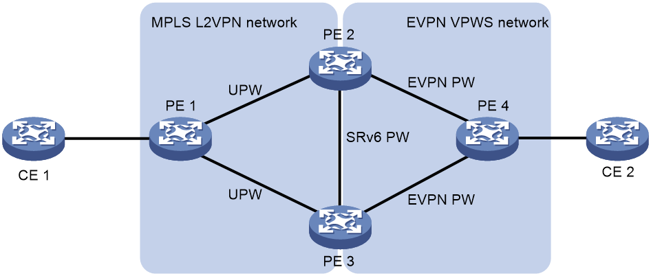
LDP or static PW ACs for EVPN PWs
This feature ensures that a traditional MPLS L2VPN (VPWS) network and an EVPN VPWS network can communicate with each other. The LDP or static PWs in the VPWS network are configured as ACs to the EVPN VPWS network. These ACs are referred to as UPWs in the EVPN VPWS network. Packets are forwards between EVPN PWs and UPWs, so the VPWS and EVPN VPWS networks can communicate with each other.
With this feature, a PE in the VPWS network can be single-homed or dual-homed to an EVPN VPWS network. As shown in Figure 15, PE 1 in the VPWS network is connected to PE 2 and PE 3 through LDP or static PWs. One of the PWs is the primary PW and the other PW is the backup PW. The PWs are UPWs. In the EVPN VPWS network, PE 4 is connected to PE 2 and PE 3 through EVPN PWs. The UPWs in the VPWS network act as ACs to the EVPN VPWS network. When PE 2 or PE 3 receives packets from the UPWs, it removes MPLS encapsulation from the packets and looks up the MAC address table for a matching EVPN PW. Then, the PE adds MPLS encapsulation to the packets and forwards the packets through the matching EVPN PW to PE 4. When PE 2 or PE 3 receives packets from an EVPN PW, it uses the same procedure to process the packets.
Figure 15 LDP or static PW ACs for EVPN PWs
Restrictions: Hardware compatibility with VXLAN VPWS
Only the following cards support VXLAN VPWS:
|
Card category |
Cards |
|
CEPC |
CEPC-XP4LX, CEPC-XP24LX, CEPC-XP48RX, CEPC-CP4RX, CEPC-CP4RXA, CEPC-CP4RX-L, CEPC-CQ8L, CEPC-CQ8LA, CEPC-CQ8L1A, CEPC-CQ16L1 |
|
CSPEX |
CSPEX-1304X, CSPEX-1404X, CSPEX-1502X, CSPEX-1504X, CSPEX-1504XA, CSPEX-1602X, CSPEX-1602XA, CSPEX-1804X, CSPEX-1512X, CSPEX-1612X, CSPEX-1812X, CSPEX-1802X, CSPEX-1802XA, CSPEX-2612XA, CSPEX-1812X-E, CSPEX-2304X-G, CSPEX-1502XA |
|
SPE |
RX-SPE200, RX-SPE200-E |
VXLAN VPWS multihoming is supported only by the following cards when the device is operating in standard mode.
|
Card category |
Cards |
|
CEPC |
CEPC-CQ8L, CEPC-CQ8LA, CEPC-CQ8L1A, CEPC-CQ16L1 |
|
CSPEX |
CSPEX-1802X, CSPEX-1802XA, CSPEX-2612XA, CSPEX-1812X-E, CSPEX-2304X-G, CSPEX-1502XA |
|
SPE |
RX-SPE200-E |
EVPN VPWS tasks at a glance
Configuring a remote connection
To configure a remote connection, perform the following tasks:
2. Configure an AC
¡ Configuring a Layer 3 interface with Ethernet or VLAN encapsulation
¡ Configuring an Ethernet service instance on an interface
3. Configuring EVPN route advertisement
a. Enabling BGP to advertise BGP EVPN routes
b. Enabling the device to advertise MPLS-encapsulated BGP EVPN routes
c. (Optional.) Configuring attributes of BGP EVPN routes
d. (Optional.) Configuring optimal BGP EVPN route selection
e. (Optional.) Configuring BGP route reflection
f. (Optional.) Filtering BGP EVPN routes
g. (Optional.) Advertising BGP RPKI validation state to a peer or peer group
h. (Optional.) Configuring BGP soft-reset by saving route updates
i. (Optional.) Maintaining BGP sessions
4. Configuring a cross-connect
a. (Optional.) Configuring a PW class
6. Mapping an AC to a cross-connect
7. (Optional.) Configuring EVPN VPWS multihoming
a. Assigning an ESI to an interface
b. (Optional.) Configuring the DF election algorithm
c. (Optional.) Setting the redundancy mode on an interface
d. (Optional.) Setting the DF election delay
e. (Optional.) Enabling fast DF/BDF switchover
f. (Optional.) Disabling advertisement of EVPN multihoming routes
g. (Optional.) Enabling the device to ignore the Ethernet tag when advertising Ethernet auto-discovery routes and MAC/IP advertisement routes
h. (Optional.) Enabling the device to monitor the BGP peer status of another local edge device
i. (Optional.) Enabling cross-connects to ignore the state of ACs
8. (Optional.) Configuring FRR for EVPN VPWS
9. (Optional.) Configuring LDP or static PWs as ACs for EVPN PWs
10. (Optional.) Testing the connectivity of an EVPN PW
Configuring PW concatenation
To configure PW concatenation, perform the following tasks:
2. Configuring a cross-connect
To concatenate two PWs, create them on the same cross-connect.
a. (Optional.) Configuring a PW class
4. (Optional.) Testing the connectivity of an EVPN PW
Prerequisites for EVPN VPWS
To configure EVPN VPWS, you must perform the following tasks:
1. Configure an IGP to achieve IP connectivity within the backbone.
2. Configure basic MPLS, LDP, GRE, or MPLS TE to set up public tunnels across the backbone.
Enabling L2VPN
Prerequisites
Before you enable L2VPN, perform the following tasks:
· Configure an LSR ID for the PE by using the mpls lsr-id command.
· Enable MPLS by using the mpls enable command on the transport-facing interface of the PE.
For more information about the mpls lsr-id and mpls enable commands, see MPLS Command Reference.
Procedure
1. Enter system view.
system-view
2. Enable L2VPN.
l2vpn enable
By default, L2VPN is disabled.
Configuring a Layer 3 interface with Ethernet or VLAN encapsulation
About this task
Configure a Layer 3 interface on a PE to establish an AC to the CE. On a Layer 3 Ethernet interface, both the PW data encapsulation type and access mode are Ethernet. On a Layer 3 Ethernet subinterface, both the PW data encapsulation type and access mode are VLAN.
Restrictions and guidelines
The PE forwards packets received from a Layer 3 interface through the bound PW without network layer processing. Therefore, the Layer 3 interface does not need an IP address.
Procedure
1. Enter system view.
system-view
2. Enter interface view.
interface interface-type interface-number
Configuring an Ethernet service instance on an interface
About this task
When the PE is connected to a CE through a Layer 2 Ethernet interface or Layer 2 aggregate interface, you can configure an Ethernet service instance on the interface to match packets for the AC.
Restrictions and guidelines
You cannot repeat the encapsulation command to modify the frame match criterion of an Ethernet service instance. To change the frame match criterion, first execute the undo encapsulation command to remove the original frame match criterion.
If the frame match criterion of an Ethernet service instance is removed, the binding between the Ethernet service instance and the cross-connect is removed automatically.
For more information about the MPLS L2VPN commands used in this task, see MPLS Command Reference.
Procedure
1. Enter system view.
system-view
2. Enter interface view.
¡ Enter Layer 2 Ethernet interface view.
interface interface-type interface-number
¡ Enter Layer 2 aggregate interface view.
interface bridge-aggregation interface-number
3. Create an Ethernet service instance and enter Ethernet service instance view.
service-instance instance-id
¡ Match packets with the specified outer VLAN ID.
encapsulation s-vid vlan-id
By default, no frame match criterion is configured.
Configuring EVPN route advertisement
Restrictions and guidelines for EVPN route advertisement configuration
For more information about the BGP commands used in this task, see Layer 3—IP Routing Command Reference.
Enabling BGP to advertise BGP EVPN routes
1. Enter system view.
system-view
2. Configure a global router ID.
router id router-id
By default, no global router ID is configured.
3. Enable a BGP instance and enter BGP instance view.
bgp as-number [ instance instance-name ]
By default, BGP is disabled and no BGP instances exist.
4. Specify remote PEs as BGP peers.
peer { group-name | ipv4-address [ mask-length ] } as-number as-number
5. Create the BGP EVPN address family and enter BGP EVPN address family view.
address-family l2vpn evpn
6. Enable BGP to exchange BGP EVPN routes with a peer or peer group.
peer { group-name | ipv4-address [ mask-length ] } enable
By default, BGP does not exchange BGP EVPN routes with peers.
Enabling the device to advertise MPLS-encapsulated BGP EVPN routes
About this task
Perform this task on PEs for them to establish PWs.
Procedure
1. Enter system view.
system-view
2. Enter BGP instance view.
bgp as-number [ instance instance-name ]
3. Enter BGP EVPN address family view.
address-family l2vpn evpn
4. Enable MPLS encapsulation for the BGP EVPN routes advertised to a peer or peer group.
peer { group name | ipv4-address [ mask-length ] | ipv6-address [ prefix-length ] } advertise encap-type mpls
By default, BGP EVPN routes use VXLAN encapsulation.
Configuring attributes of BGP EVPN routes
1. Enter system view.
system-view
2. Enter BGP instance view.
bgp as-number [ instance instance-name ]
3. Enter BGP EVPN address family view.
address-family l2vpn evpn
4. Set a preferred value for routes received from a peer or peer group.
peer { group-name | ipv4-address [ mask-length ] | ipv6-address [ prefix-length ] } preferred-value value
By default, the preferred value is 0 for routes received from a peer or peer group.
5. Permit the local AS number to appear in routes from a peer or peer group and set the number of appearances.
peer { group-name | ipv4-address [ mask-length ] } allow-as-loop [ number ]
By default, the local AS number is not allowed in routes from peers.
6. Configure BGP to remove or replace private AS numbers with the local AS number in BGP updates sent to an EBGP peer or peer group.
peer { group-name | ipv4-address [ mask-length ] | ipv6-address [ prefix-length ] } public-as-only [ { force | limited } [ replace ] [ include-peer-as ] ]
peer { group-name | ipv4-address [ mask-length ] | ipv6-address [ prefix-length ] } public-as-only [ force [ include-peer-as ] ] keep-local-as
By default, BGP updates sent to an EBGP peer or peer group can carry both public and private AS numbers.
7. Configure the device to not change the next hop of routes advertised to an EBGP peer or peer group.
peer { group-name | ipv4-address [ mask-length ] } next-hop-invariable
By default, the device uses its address as the next hop of routes advertised to EBGP peers.
8. Configure the device to advertise route attributes to a peer or peer group:
¡ Advertise the COMMUNITY attribute to a peer or peer group.
peer { group-name | ipv4-address [ mask-length ] } advertise-community
By default, the device does not advertise the COMMUNITY attribute to peers or peer groups.
¡ Advertise the Large attribute to a peer or peer group.
peer { group-name | ipv4-address [ mask-length ] } advertise-large-community
By default, the device does not advertise the Large attribute to peers or peer groups.
9. Configure the SoO attribute for a peer or peer group.
peer { group-name | ipv4-address [ mask-length ] | ipv6-address [ prefix-length ] } soo site-of-origin
By default, no SoO attribute is configured for a peer or peer group.
10. Enable BGP to add the link bandwidth attribute to routes received from a BGP peer or peer group.
peer { group-name | ipv4-address [ mask-length ] | ipv6-address [ prefix-length ] } bandwidth
By default, BGP does not add the link bandwidth attribute to routes received from a BGP peer or peer group.
Configuring optimal BGP EVPN route selection
1. Enter system view.
system-view
2. Enter BGP instance view.
bgp as-number [ instance instance-name ]
3. Enter BGP EVPN address family view.
address-family l2vpn evpn
4. Configure optimal route selection:
¡ Prefer routes learned from the specified peer or peer group during optimal route selection.
peer { group-name | ipv4-address [ mask-length ] | ipv6-address [ prefix-length ] } high-priority
By default, BGP does not prefer routes learned from any peer or peer groups during optimal route selection.
¡ Set the optimal route selection delay timer.
route-select delay delay-value
By default, the optimal route selection delay timer is 0 seconds, which means optimal route selection is not delayed.
5. Configure BGP route dampening:
¡ Configure EBGP route dampening.
dampening [ half-life-reachable half-life-unreachable reuse suppress ceiling | route-policy route-policy-name ] *
For more information about this command, see BGP commands in Layer 3—IP Routing Command Reference.
¡ Configure IBGP route dampening.
dampening ibgp [ half-life-reachable half-life-unreachable reuse suppress ceiling | route-policy route-policy-name ] *
For more information about this command, see MPLS L3VPN commands in MPLS Command Reference.
By default, BGP route dampening is not configured.
For more information about route dampening, see BGP configuration in Layer 3—IP Routing Configuration Guide.
6. Set the delay time for responding to recursive next hop changes.
nexthop recursive-lookup [ non-critical-event ] delay [ delay-value ]
By default, BGP responds to recursive next hop changes immediately.
7. Configure the BGP Add-Path feature:
¡ Configure the BGP additional path capabilities.
peer { group-name | ipv4-address [ mask-length ] } additional-paths { receive | send } *
By default, no BGP additional path capabilities are configured.
¡ Set the maximum number of Add-Path optimal routes that can be advertised to a peer or peer group.
peer { group-name | ipv4-address [ mask-length ] } advertise additional-paths best number
By default, a maximum number of one Add-Path optimal route can be advertised to a peer or peer group.
¡ Set the maximum number of Add-Path optimal routes that can be advertised to all peers.
additional-paths select-best best-number
By default, a maximum number of one Add-Path optimal route can be advertised to all peers.
8. Limit the total number of BGP EVPN routes that can be received from a peer or peer group.
peer { group-name | ipv4-address [ mask-length ] | ipv6-address [ prefix-length ] } route-limit prefix-number [ { alert-only| discard | reconnect reconnect-time } | percentage-value ] *
By default, the device does not limit the number of BGP EVPN routes that can be received from a peer or peer group.
Configuring BGP route reflection
1. Enter system view.
system-view
2. Enter BGP instance view.
bgp as-number [ instance instance-name ]
3. Enter BGP EVPN address family view.
address-family l2vpn evpn
4. Configure the device as an RR and specify a peer or peer group as its client.
peer { group-name | ipv4-address [ mask-length ] } reflect-client
By default, no RR or client is configured.
5. (Optional.) Enable BGP EVPN route reflection between clients.
reflect between-clients
By default, BGP EVPN route reflection between clients is enabled.
6. (Optional.) Configure the cluster ID of the RR.
reflector cluster-id { cluster-id | ipv4-address }
By default, an RR uses its own router ID as the cluster ID.
7. (Optional.) Create a reflection policy for the RR to filter reflected BGP EVPN routes.
rr-filter { ext-comm-list-number | ext-comm-list-name }
By default, an RR does not filter reflected BGP EVPN routes.
8. (Optional.) Enable the route reflector to change the attributes of routes to be reflected.
reflect change-path-attribute
By default, an RR does not filter reflected BGP EVPN routes.
9. (Optional.) Add a peer or peer group to the nearby cluster.
peer { group-name | ipv4-address [ mask-length ] } reflect-nearby-group
By default, the nearby cluster does not have any peers or peer groups.
The RR does not change the next hop of routes reflected to peers and peer groups in the nearby cluster.
Filtering BGP EVPN routes
1. Enter system view.
system-view
2. Enter BGP instance view.
bgp as-number [ instance instance-name ]
3. Enter BGP EVPN address family view.
address-family l2vpn evpn
4. Enable route target filtering for BGP EVPN routes.
policy vpn-target
By default, route target filtering is enabled for BGP EVPN routes.
5. Apply a routing policy to routes received from or advertised to a peer or peer group.
peer { group-name | ipv4-address [ mask-length ] } route-policy route-policy-name { export | import }
By default, no routing policies are applied to routes received from or advertised to peers or peer groups.
6. Specify a routing policy as the existent policy to control route advertisement.
peer { group-name | ipv4-address [ mask-length ] | ipv6-address [ prefix-length ] } advertise-policy advertise-policy-name exist-policy exist-policy-name
By default, advertisement of BGP EVPN routes is not controlled.
7. Specify a routing policy as the nonexistent policy to control route advertisement.
peer { group-name | ipv4-address [ mask-length ] | ipv6-address [ prefix-length ] } advertise-policy advertise-policy-name non-exist-policy non-exist-policy-name
By default, advertisement of BGP EVPN routes is not controlled.
Advertising BGP RPKI validation state to a peer or peer group
Restrictions and guidelines
BGP advertises the BGP RPKI validation state to a peer or peer group through the extended community attribute. For more information about BGP RPKI validation, see BGP configuration in Layer 3—IP Routing Configuration Guide.
Procedure
1. Enter system view.
system-view
2. Enter BGP instance view.
bgp as-number [ instance instance-name ]
3. Enter BGP EVPN address family view.
address-family l2vpn evpn
4. Advertise the BGP RPKI validation state to the specified peer or peer group.
peer { group-name | ipv4-address [ mask-length ] | ipv6-address [ prefix-length ] } advertise origin-as-validation
By default, BGP does not advertise the BGP RPKI validation state.
Configuring BGP soft-reset by saving route updates
About this task
Perform this task if the device does not support route refresh. The device will save all route updates received from peers. After the route selection policy is modified, the device filters routing information by using the new policy to implement BGP soft-reset.
Restrictions and guidelines
For more information about route refresh and BGP soft-reset, see BGP configuration in Layer 3—IP Routing Configuration Guide.
Procedure
1. Enter system view.
system-view
2. Enter BGP instance view.
bgp as-number [ instance instance-name ]
3. Enter BGP EVPN address family view.
address-family l2vpn evpn
4. Save all route updates from a peer or peer group.
peer { group-name | ipv4-address [ mask-length ] | ipv6-address [ prefix-length ] } keep-all-routes
By default, route updates from peers and peer groups are not saved.
Maintaining BGP sessions
Perform the following tasks in user view:
· Reset BGP sessions of the BGP EVPN address family.
reset bgp [ instance instance-name ] { as-number | ipv4-address [ mask-length ] | ipv6-address [ prefix-length ] | all | external | group group-name | internal } l2vpn evpn
· Soft-reset BGP sessions of the BGP EVPN address family.
refresh bgp [ instance instance-name ] { ipv4-address [ mask-length ] | ipv6-address [ prefix-length ] | all | external | group group-name | internal } { export | import } l2vpn evpn
Configuring a cross-connect
Restrictions and guidelines
For more information about the cross-connect commands used in this task, see MPLS L2VPN commands in MPLS Command Reference.
Procedure
1. Enter system view.
system-view
2. Create a cross-connect group and enter cross-connect group view.
xconnect-group group-name
3. (Optional.) Configure a description for the cross-connect group.
description text
By default, no description is configured for a cross-connect group.
4. (Optional.) Enable the cross-connect group.
undo shutdown
By default, the cross-connect group is enabled.
5. Create a cross-connect and enter cross-connect view.
connection connection-name
Configuring a PW
Configuring a PW class
About this task
You can configure PW attributes such as the PW data encapsulation type and enable control word in a PW class. PWs with the same attributes can use the same PW class.
Restrictions and guidelines
For more information about the PW class commands used in this task, see MPLS L2VPN commands in MPLS Command Reference.
You must configure the same data encapsulation type on two PEs that are connected by the same PW.
For correct PW setup, make sure the status of the control word feature is the same on the two PEs that are connected by the same PW.
Procedure
1. Enter system view.
system-view
2. Create a PW class and enter PW class view.
pw-class class-name
3. Enable control word.
control-word enable
By default, control word is disabled.
4. Specify the PW data encapsulation type.
pw-type { ethernet | vlan }
By default, the PW data encapsulation type is VLAN.
5. Enable the flow label feature and configure flow label capabilities.
flow-label { both | receive | send } static
By default, the flow label feature is disabled.
EVPN VPWS does not support flow label capability negotiation for dynamic PWs in the current software version. For this command to take effect, you must specify the static keyword.
6. Specify the VCCV CC type.
vccv cc { control-word | router-alert | ttl }
By default, no VCCV CC type is specified.
For more information about this command, see MPLS OAM commands in MPLS Command Reference.
Configuring an EVPN PW
About this task
To establish an EVPN PW between two PEs, specify a local service ID and a remote service ID on both PEs. The local service ID specified on one PE must be the same as the remote service ID specified on the other PE.
In cross-connect group EVPN instance view, you can configure routing policies to filer the routes redistributed from BGP EVPN to an EVPN instance and vice versa.
Restrictions and guidelines
To modify an EVPN PW, first use the undo evpn local-service-id remote-service-id command to delete the original EVPN PW.
Procedure
1. Enter system view.
system-view
2. Enter cross-connect group view.
xconnect-group group-name
3. Create an EVPN instance for the cross-connect group and enter its view.
evpn encapsulation mpls
4. Configure an RD for the EVPN instance.
route-distinguisher route-distinguisher
By default, no RD is configured for the EVPN instance of a cross-connect group.
5. Configure route targets for the EVPN instance.
vpn-target { vpn-target&<1-8> } [ both | export-extcommunity | import-extcommunity ]
By default, no route targets are configured for the EVPN instance of a cross-connect group.
Make sure the following requirements are met:
¡ The import targets of the EVPN instance of a cross-connect group do not match the export targets of a VPN instance, the public instance, or the EVPN instance of a VSI.
¡ The export targets of the EVPN instance of a cross-connect group do not match the import targets of a VPN instance, the public instance, or the EVPN instance of a VSI.
6. (Optional.) Apply an export routing policy to the EVPN instance.
export route-policy route-policy
By default, no export routing policy is applied to an EVPN instance.
7. (Optional.) Apply an import routing policy to the EVPN instance.
import route-policy route-policy
By default, no import routing policy is applied to an EVPN instance.
8. Return to cross-connect group view.
quit
9. Enter cross-connect view.
connection connection-name
10. (Optional.) Set an MTU for the PW.
mtu size
The default MTU is 1500 bytes.
11. Configure an EVPN PW and enter its view.
evpn local-service-id local-service-id remote-service-id remote-service-id [ tunnel-policy tunnel-policy-name ] [ pw-class class-name ]
Do not use this command together with the peer command for a cross-connect.
Mapping an AC to a cross-connect
About mapping an AC to a cross-connect
After you map a Layer 3 interface or Ethernet service instance to a cross-connect, packets received from the mapped AC are forwarded to the PW or another AC bound to the cross-connect.
An Ethernet service instance matches a list of VLANs on a site-facing interface. The PE assigns customer traffic from the VLANs to a cross-connect by mapping the Ethernet service instance to the cross-connect.
When you map an AC to a cross-connect, you can associate Track with the AC. Then, the AC is up only when one or more of the associated track entries are positive.
Restrictions and guidelines for mapping an AC to a cross-connect
This task is mutually exclusive with Ethernet link aggregation. If a Layer 2 or Layer 3 Ethernet interface has been added to a link aggregation group, you cannot map the Layer 3 interface or an Ethernet service instance on the Layer 2 interface to a cross-connect, and vice versa.
Mapping a Layer 3 interface to a cross-connect
1. Enter system view.
system-view
2. Enter cross-connect group view.
xconnect-group group-name
3. Enter cross-connect view.
connection connection-name
4. Map a Layer 3 interface to the cross-connect.
ac interface interface-type interface-number [ access-mode { ethernet | vlan } ] [ track track-entry-number&<1-3> ] [ access-evpn ]
By default, no Layer 3 interface is bound to the cross-connect.
Mapping an Ethernet service instance to a cross-connect
1. Enter system view.
system-view
2. Enter cross-connect group view.
xconnect-group group-name
3. Enter cross-connect view.
connection connection-name
4. Map an Ethernet service instance to the cross-connect.
ac interface interface-type interface-number service-instance instance-id [ access-mode { ethernet | vlan } ] [ track track-entry-number&<1-3> ] [ access-evpn ]
By default, no Ethernet service instance is mapped to a cross-connect.
Configuring EVPN VPWS multihoming
Restrictions and guidelines for EVPN VPWS multihoming
You must configure the same local and remote service IDs on the redundant PEs at a multihomed site.
As a best practice, set the same redundancy mode on the interfaces that act as ACs or are configured with ACs on the redundant PEs at a multihomed site.
You can assign ESIs to a main interface and its subinterfaces.
· If you assign an ESI to a subinterface, the subinterface-specific ESI and ES configuration take precedence over those configured on the main interface. The ES configuration includes the following:
¡ evpn redundancy-mode.
¡ evpn df-election algorithm.
¡ evpn df-election preference.
¡ evpn df-election preference non-revertive.
¡ evpn timer es-delay.
· If you do not assign an ESI to a subinterface, it inherits the ESI and ES configuration (if configured) of the main interface. In this scenario, the ES configuration on the subinterface does not take effect.
If you set up an EVPN PW with a redundant PE at the local site, the device uses the BFD configuration in the PW class specified in the evpn local-service-id remote-service-id command.
· If the EVPN PW is a primary EVPN PW, the device establishes a dynamic BFD session for the EVPN PW.
· If the EVPN PW is a backup or ECMP EVPN PW, the device does not establish a dynamic BFD session for the EVPN PW.
Assigning an ESI to an interface
About this task
An ESI uniquely identifies an ES. The links on interfaces with the same ESI belong to the same ES. Traffic of the ES can be distributed among the links for load sharing.
Procedure
1. Enter system view.
system-view
2. Enter interface view.
¡ Enter Layer 2 Ethernet interface view.
interface interface-type interface-number
¡ Enter Layer 2 aggregate interface view.
interface bridge-aggregation interface-number
¡ Enter Layer 3 Ethernet interface view.
interface interface-type interface-number
¡ Enter Layer 3 aggregate interface view.
interface route-aggregation interface-number
¡ Enter FlexE physical interface view.
interface interface-type interface-number
¡ Enter FlexE logical interface view.
interface flexe interface-number
3. Assign an ESI to the interface.
esi esi-id
By default, no ESI is assigned to an interface.
Configuring the DF election algorithm
About this task
At a multihomed EVPN network site, you can modify the DF election algorithm to control the DF election result.
Restrictions and guidelines
If the ambiguous VLAN termination is configured on a subinterface acting as an AC, do not use the VLAN tag-based DF election algorithm. If you use the algorithm, traffic forwarding errors might occur.
You can configure the DF election algorithm in system view and in interface view. The global DF election algorithm takes effect on all ESs, and the interface-specific DF election algorithm takes effect only on the ESs on an interface. The interface-specific DF election algorithm takes precedence over the global DF election algorithm.
Configuring the DF election algorithm globally
1. Enter system view.
system-view
2. Configure the DF election algorithm.
evpn df-election algorithm algorithm
By default, the VLAN tag-based algorithm is used for DF election.
Configuring the DF election algorithm on an interface
1. Enter system view.
system-view
2. Enter interface view.
¡ Enter Layer 2 Ethernet interface view.
interface interface-type interface-number
¡ Enter Layer 2 aggregate interface view.
interface bridge-aggregation interface-number
¡ Enter Layer 3 Ethernet interface view.
interface interface-type interface-number
¡ Enter Layer 3 aggregate interface view.
interface route-aggregation interface-number
¡ Enter FlexE physical interface view.
interface interface-type interface-number
¡ Enter FlexE logical interface view.
interface flexe interface-number
3. Configure the DF election algorithm.
evpn df-election algorithm algorithm
By default, the DF election algorithm specified in system view takes effect.
Configuring preference-based DF election
1. Enter system view.
system-view
2. Enter interface view.
¡ Enter Layer 2 Ethernet interface view.
interface interface-type interface-number
¡ Enter Layer 2 aggregate interface view.
interface bridge-aggregation interface-number
¡ Enter Layer 3 Ethernet interface view.
interface interface-type interface-number
¡ Enter Layer 3 aggregate interface view.
interface route-aggregation interface-number
¡ Enter FlexE physical interface view.
interface interface-type interface-number
¡ Enter FlexE logical interface view.
interface flexe interface-number
3. Set the DF election preference.
evpn df-election preference preference
By default, the DF election preference is 32767.
The larger the value, the higher the preference.
4. (Optional.) Enable non-revertive mode for preference-based DF election.
evpn df-election preference non-revertive
By default, non-revertive mode is disabled for preference-based DF election.
Setting the redundancy mode on an interface
About this task
EVPN VPWS multihoming provides the single-active redundancy mode and all-active redundancy mode.
The redundant PEs at a dualhomed site each establish an EVPN PW to a remote PE. To use one PW as a backup of the other PW, use the single-active mode. To distribute traffic across the PWs for load sharing, use the all-active mode.
Restrictions and guidelines
When you configure S-Trunk on the redundant PEs at a dualhomed site, follow these restrictions:
· In single-active redundancy mode, execute the s-trunk port-role auto command on the PEs.
· In all-active redundancy mode, execute the s-trunk port-role primary command on the PEs.
For more information about S-Trunk, see High Availability Configuration Guide.
Procedure
1. Enter system view.
system-view
2. Enter interface view.
¡ Enter Layer 2 Ethernet interface view.
interface interface-type interface-number
¡ Enter Layer 2 aggregate interface view.
interface bridge-aggregation interface-number
¡ Enter Layer 3 Ethernet interface view.
interface interface-type interface-number
¡ Enter Layer 3 aggregate interface view.
interface route-aggregation interface-number
¡ Enter FlexE physical interface view.
interface interface-type interface-number
¡ Enter FlexE logical interface view.
interface flexe interface-number
3. Set the redundancy mode.
evpn redundancy-mode { all-active | single-active }
By default, the all-active redundancy mode is used.
Setting the DF election delay
About this task
The DF election can be triggered by site-facing interface status changes, redundant PE membership changes, and interface ESI changes. To prevent frequent DF elections from degrading network performance, set the DF election delay. The DF election delay defines the minimum interval allowed between two DF elections.
Procedure
1. Enter system view.
system-view
2. Set the DF election delay.
evpn multihoming timer df-delay delay-value
By default, the DF election delay is 3 seconds.
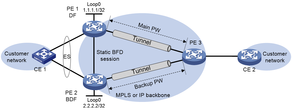
Enabling fast DF/BDF switchover
About this task
As shown in Figure 16, CE 1 is dualhomed to PE 1 (DF) and PE 2 (BDF) in an EVPN VPWS network. PE 2 cannot take over the DF role immediately when the AC on PE 1 fails, and traffic loss will occur as a result. To resolve this issue, set up a static BFD session between PE 1 and PE 2. You must configure the static BFD session to monitor the status of the local AC on PE 1 and enable PE 2 to monitor the status of the session. When the AC on PE 1 fails, the static BFD session goes down, and PE 2 can fast take over the DF role to reduce traffic loss.
Figure 16 Application scenario for fast DF/BDF switchover
Configuring the DF
1. Enter system view.
system-view
2. Create a static BFD session and configure it to monitor an AC-side interface.
bfd static session-name peer-ip ipv4-address [ vpn-instance vpn-instance-name ] source-ip ipv4-address discriminator local local-value remote remote-value track-interface interface-type interface-number
For more information about this command, see High Availability Command Reference.
Configuring the BDF
1. Enter system view.
system-view
2. Create a static BFD session.
bfd static session-name peer-ip ipv4-address [ vpn-instance vpn-instance-name ] source-ip ipv4-address discriminator local local-value remote remote-value
For more information about this command, see High Availability Command Reference.
3. Enter interface view.
¡ Enter Layer 3 Ethernet interface view.
interface interface-type interface-number
¡ Enter Layer 3 aggregate interface view.
interface route-aggregation interface-number
¡ Enter FlexE logical interface view.
interface flexe interface-number
4. Enable the device to monitor the status of the static BFD session.
evpn track bfd session-name
By default, the device does not monitor the status of static BFD sessions.
Disabling advertisement of EVPN multihoming routes
About this task
EVPN multihoming routes include Ethernet auto-discovery routes and Ethernet segment routes.
In a multihomed EVPN network, perform this task on a redundant PE before you reboot it. This operation allows other PEs to refresh their EVPN routing table to prevent traffic interruption caused by the reboot.
Procedure
1. Enter system view.
system-view
2. Disable advertisement of EVPN multihoming routes and withdraw the EVPN multihoming routes that have been advertised to remote sites.
evpn multihoming advertise disable
By default, the device advertises EVPN multihoming routes.
Enabling the device to ignore the Ethernet tag when advertising Ethernet auto-discovery routes and MAC/IP advertisement routes
About this task
This task enables the device to withdraw the Ethernet auto-discovery routes and MAC/IP advertisement routes that have been advertised, set their Ethernet tag field to 0, and then re-advertise them.
After you configure ESIs for ACs on the redundant edge devices at a dualhomed site, the edge devices advertise Ethernet auto-discovery routes and MAC/IP advertisement routes that carry Ethernet tags. If the remote peers are unable to identify Ethernet tags, you must perform this task on the redundant edge devices to enable communication with the peers.
Restrictions and guidelines
After you assign an ESI to a Layer 2 Ethernet or aggregate interface, you must map the Ethernet service instances created on the interface to different VSIs. If two interfaces use the same ESI, you must map the Ethernet service instances created on them to different VSIs.
After you assign an ESI to a Layer 3 main interface, its subinterfaces inherit the ESI if they do not have one. In addition, you must map two subinterfaces to different VSIs if the subinterfaces have the same ESI.
Procedure
1. Enter system view.
system-view
2. Enable the device to ignore the Ethernet tag when advertising Ethernet auto-discovery routes and MAC/IP advertisement routes.
evpn multihoming advertise ignore-ethernet-tag
By default, the device advertises Ethernet auto-discovery routes and MAC/IP advertisement routes that carry Ethernet tags.
Enabling the device to monitor the BGP peer status of another local edge device
About this task
Perform this task on the CE-facing interfaces of the edge devices multihomed to a site to prevent device reboots from causing inter-site forwarding failure.
This task excludes unavailable edge devices from DF election at a multihomed site. After an edge device recovers from failure and brings up its CE-facing interface, it starts the advertisement delay timer for Ethernet segment routes and checks the status of the BGP peer specified in the evpn track peer command. If the BGP peer comes up before the timer expires, the edge device advertises Ethernet segment routes to the peer. If the BGP peer is still down when the timer expires, the edge device does not advertise Ethernet segment routes to the peer. The edge devices then perform DF election based on the Ethernet segment routes they have received.
Procedure
1. Enter system view.
system-view
2. Enter interface view.
¡ Enter Layer 2 Ethernet interface view.
interface interface-type interface-number
¡ Enter Layer 2 aggregate interface view.
interface bridge-aggregation interface-number
¡ Enter Layer 3 Ethernet interface view.
interface interface-type interface-number
¡ Enter Layer 3 aggregate interface view.
interface route-aggregation interface-number
¡ Enter FlexE physical interface view.
interface interface-type interface-number
¡ Enter FlexE logical interface view.
interface flexe interface-number
3. Enable the device to monitor the BGP peer status of another local edge device.
evpn track peer peer-address
By default, the device does not monitor the BGP peer status of the other edge devices at a multihomed site.
4. Set the advertisement delay timer for Ethernet segment routes.
evpn timer es-delay delay-time
By default, advertisement of Ethernet segment routes is not delayed.
Enabling cross-connects to ignore the state of ACs
About this task
This task helps reduce the traffic loss caused by AC failure at a multihomed EVPN VPWS network site that uses single-active redundancy mode.
At a multihomed EVPN VPWS network site that uses single-active redundancy mode, CE 1 is dualhomed to PE 1 and PE 2 through a smart trunk. PE 1 is the primary PE, and PE 2 is the secondary PE. When the AC on PE 1 fails, PE 1 and PE 2 act as follows:
· PE 1 withdraws advertised Ethernet auto-discovery routes.
· PE 2 brings up its AC and advertises Ethernet auto-discovery routes to remote PEs.
The remote PEs switch traffic to the paths to PE 2 only after receiving the Ethernet auto-discovery routes advertised by PE 2, and traffic loss occurs during path switchover. To resolve this issue, enable cross-connects to ignore the state of ACs on PE 2. This feature allows PE 2 to advertise Ethernet auto-discovery routes to remote PEs regardless of the state of ACs and speeds up path switchover when the AC on PE 1 fails.
Restrictions and guidelines for AC state ignore configuration
On a cross-connect, cross-connect-specific AC state ignore configuration takes precedence over global AC state ignore configuration.
Enabling cross-connects to ignore the state of ACs globally
1. Enter system view.
system-view
2. Enable cross-connects to ignore the state of ACs globally.
l2vpn ignore-ac-state [ evpn-vpws ]
By default, cross-connects does not ignore the state of ACs.
Configuring a cross-connect to ignore the state of ACs
1. Enter system view.
system-view
2. Enter cross-connect group view.
xconnect-group group-name
3. Enter cross-connect view.
connection connection-name
4. Enable the cross-connect to ignore the state of ACs or disable a cross-connect from ignoring the state of ACs.
ignore-ac-state { enable | disable }
By default, a cross-connect uses the global AC state ignore configuration.
Configuring FRR for EVPN VPWS
Configuring local FRR
About this task
Local FRR enables two PEs at a multihomed EVPN VPWS network site to set up a bypass PW between them. This feature helps reduce the traffic loss caused by AC failure.
Restrictions and guidelines
On an EVPN instance, EVPN instance-specific local FRR configuration takes precedence over global local FRR configuration.
If you have executed the evpn frr local enable command on an EVPN instance, the undo evpn multihoming vpws-frr local command does not delete the bypass PW of the EVPN instance.
Enabling local FRR globally
1. Enter system view.
system-view
2. Enable local FRR globally.
evpn multihoming vpws-frr local
By default, local FRR is disabled globally.
Configuring local FRR on an EVPN instance
1. Enter system view.
system-view
2. Enter cross-connect group view.
xconnect-group group-name
3. Enter EVPN instance view.
evpn encapsulation mpls
4. Configure local FRR.
evpn frr local { disable | enable }
By default, an EVPN instance uses the global local FRR configuration of EVPN VPWS.
Configuring remote FRR
About this task
Remote FRR enables two PEs on an EVPN VPWS network to set up a primary PW and a backup PW between them to ensure high availability. The PEs use the primary PW to forward traffic as long as it is available. When the primary PW fails, the PEs switch traffic to the backup PW.
Restrictions and guidelines
On an EVPN instance, EVPN instance-specific remote FRR configuration takes precedence over global remote FRR configuration.
If you have executed the evpn frr remote enable command on an EVPN instance, the undo evpn vpws-frr remote command does not delete the backup PWs of the EVPN instance.
Enabling remote FRR globally
1. Enter system view.
system-view
2. Enable remote FRR globally.
evpn vpws-frr remote
By default, remote FRR is disabled globally.
Configuring remote FRR on an EVPN instance
1. Enter system view.
system-view
2. Enter cross-connect group view.
xconnect-group group-name
3. Enter EVPN instance view.
evpn encapsulation mpls
4. Configure remote FRR.
evpn frr remote { disable | enable }
By default, an EVPN instance uses the global remote FRR configuration of EVPN VPWS.
Configuring LDP or static PWs as ACs for EVPN PWs
About LDP or static PW AC configuration for EVPN PWs
Use this feature for a VPWS network and an EVPN VPWS network to communicate with each other.
Restrictions and guidelines for LDP or static PW AC configuration for EVPN PWs
As a best practice, set the same redundancy mode for the UPWs that use the same ESI at a multihomed site.
You must configure the same local and remote service IDs on the PEs multihomed to the same site.
If the all-active redundancy mode is used at a multihomed site, you must enable the dual receive feature for PW redundancy on the multihomed PEs. To enable this feature, use the protection dual-receive command.
Prerequisites for LDP or static PW AC configuration for EVPN PWs
Perform the following tasks:
· In the VPWS network, configure VPWS settings on the PEs and set up LDP or static PWs.
· In the EVPN VPWS network, configure EVPN VPWS settings on the PEs and set up EVPN PWs.
Configuring an LDP PW as an AC for an EVPN PW
Restrictions and guidelines
Make sure the access mode of ACs is the same as the data encapsulation type of LDP PWs. To configure the data encapsulation type for an LDP PW, execute the pw-type command for the PW class used by the LDP PW. To configure the access mode for an AC, use the xconnect vsi command.
Procedure
1. Enter system view.
system-view
2. Enter cross-connect group view.
xconnect-group group-name
3. Enter EVPN instance view of a cross-connect group.
evpn encapsulation mpls
4. Return to cross-connect group view.
quit
5. Enter cross-connect view.
connection connection-name
6. Configure an LDP PW and enter cross-connect PW view.
peer ip-address pw-id pw-id [ ignore-standby-state ] [ admin | pw-class class-name | tunnel-policy tunnel-policy-name ] *
For more information about this command, see MPLS L2VPN commands in MPLS Command Reference.
7. (Optional.) Assign an ESI to the UPW.
esi esi-id
By default, no ESI is assigned to a PW.
In a multihoming scenario, execute this command on the border PEs that interconnect the VPWS and EVPN VPWS networks.
For more information about this command, see EVPN Command Reference.
8. (Optional.) Set the redundancy mode for the UPW.
evpn redundancy-mode { all-active | single-active }
By default, the all-active redundancy mode is used.
In a multihoming scenario, execute this command on the border PEs that interconnect the VPWS and EVPN VPWS networks.
For more information about this command, see EVPN Command Reference.
9. Configure a backup LDP PW and enter cross-connect PW view.
backup-peer ip-address pw-id pw-id [ pw-class class-name | tunnel-policy tunnel-policy-name ] *
In a multihoming scenario, execute this command on a PE multihomed to the border PEs that interconnect the VPWS and EVPN VPWS networks.
10. Return to cross-connect view.
quit
quit
11. Create an EVPN PW and enter its view.
evpn local-service-id local-service-id remote-service-id remote-service-id [ tunnel-policy tunnel-policy-name ] [ pw-class class-name ]
Do not use this command together with the peer command in cross-connect view.
Configuring a static PW as an AC for an EVPN PW
1. Enter system view.
system-view
2. Enter cross-connect group view.
xconnect-group group-name
3. Enter EVPN instance view of a cross-connect group.
evpn encapsulation mpls
4. Return to cross-connect group view.
quit
5. Enter cross-connect view.
connection connection-name
6. Configure a static PW and enter cross-connect PW view.
peer ip-address pw-id pw-id in-label label-value out-label label-value [ admin | pw-class class-name | tunnel-policy tunnel-policy-name ] *
For more information about this command, see MPLS L2VPN commands in MPLS Command Reference.
7. (Optional.) Assign an ESI to the UPW.
esi esi-id
By default, no ESI is assigned to a PW.
In a multihoming scenario, execute this command on the border PEs that interconnect the VPWS and EVPN VPWS networks.
For more information about this command, see EVPN Command Reference.
8. (Optional.) Set the redundancy mode for the UPW.
evpn redundancy-mode { all-active | single-active }
By default, the all-active redundancy mode is used.
In a multihoming scenario, execute this command on the border PEs that interconnect the VPWS and EVPN VPWS networks.
For more information about this command, see EVPN Command Reference.
9. Configure a backup static PW and enter cross-connect PW view.
backup-peer ip-address pw-id pw-id in-label label-value out-label label-value [ pw-class class-name | tunnel-policy tunnel-policy-name ] *
In a multihoming scenario, execute this command on a PE multihomed to the border PEs that interconnect the VPWS and EVPN VPWS networks.
10. Return to cross-connect view.
quit
quit
11. Create an EVPN PW and enter its view.
evpn local-service-id local-service-id remote-service-id remote-service-id [ tunnel-policy tunnel-policy-name ] [ pw-class class-name ]
Do not use this command together with the peer command in cross-connect view.
Testing the connectivity of an EVPN PW
Prerequisites for EVPN PW connectivity test
To test the connectivity of an EVPN PW, configure the PW to use a PW class whose VCCV control channel type has been configured by using the vccv cc command.
Pinging a PW destination
About this task
Perform this task to test the connectivity of a PW when the PW has traffic loss or interruption issues in an EVPN VPWS network. The process of a ping operation is as follows:
1. The PW source PE sends MPLS echo requests to the PW destination PE based on the cross-connect group, and local and remote service IDs you specify.
2. The PW destination PE responds with MPLS echo replies.
3. The PW source PE outputs packet statistics and the test result based on the received MPLS echo replies.
Procecure
Execute the following command in any view.
ping evpn vpws xconnect-group group-name local-service-id remote-service-id [ -a source-ip | -c count | -exp exp-value | -m interval | -r reply-mode | -s packet-size | -t time-out ] *
Tracing the path to a PW destination
About this task
Perform this task to locate failed nodes on the path for a PW that has traffic loss or interruption issues in an EVPN VPWS network. The process of a tracert operation is as follows:
1. The PW source PE sends MPLS echo requests to the PW destination PE based on the cross-connect group, and local and remote service IDs you specify. The TTL in the IP header of the requests is set to 1.
2. The first hop on the path responds to the PW source PE with a TTL-expired ICMP error message.
3. The PW source PE sends MPLS echo requests with the TTL set to 2 if the PE receives the TTL-expired ICMP error message or has not received any packets within the timeout period.
4. The second hop responds with a TTL-expired ICMP error message.
5. This process continues until an MPLS echo request reaches the PW destination PE or the maximum TTL value is reached. If an MPLS echo request reaches the PW destination PE, the PW destination PE sends an MPLS echo reply to the PW source PE.
6. The PW source PE outputs packet statistics and the test result based on the received ICMP error messages and whether an MPLS echo reply is received.
Procecure
Execute the following command in any view.
tracert evpn vpws xconnect-group group-name local-service-id remote-service-id [ -a source-ip | -exp exp-value | -h ttl-value | -r reply-mode | -t time-out ] * [ ddmap | full-lsp-path ] *
Display and maintenance commands for EVPN VPWS
Execute display commands in any view and reset commands in user view.
For more information about the following BGP commands, see Layer 3—IP Routing Command Reference:
· display bgp group.
· display bgp peer.
· display bgp update-group.
|
Task |
Command |
|
Display BGP peer group information. |
display bgp [ instance instance-name ] group l2vpn evpn [ group-name group-name ] |
|
Display BGP EVPN routes. |
display bgp [ instance instance-name ] l2vpn evpn [ peer ipv4-address { advertised-routes | received-routes } [ { evpn-route route-length | evpn-prefix } [ verbose ] | statistics ] | [ route-distinguisher route-distinguisher | route-type { auto-discovery | es | imet | mac-ip } ] * [ { evpn-route route-length | evpn-prefix } [ advertise-info ] | ipv4-address | mac-address ] | statistics ] display bgp [ instance instance-name ] l2vpn evpn [ peer ipv4-address { accepted-routes | not-accepted-routes } ] |
|
Display BGP peer or peer group information. |
display bgp [ instance instance-name ] peer l2vpn evpn [ ipv4-address mask-length | { ipv4-address | group-name group-name } log-info | [ ipv4-address ] verbose ] |
|
Display information about BGP update groups. |
display bgp [ instance instance-name ] update-group l2vpn evpn [ ipv4-address ] |
|
Display dampened BGP EVPN routes. |
display bgp [ instance instance-name ] l2vpn evpn dampened |
|
Display BGP EVPN route dampening parameters. |
display bgp [ instance instance-name ] dampening parameter l2vpn evpn |
|
Display flapping statistics about BGP EVPN routes. |
display bgp [ instance instance-name ] l2vpn evpn flap-info |
|
Display the route targets sourced from the EVPN process and ES-import route targets for BGP. |
display bgp [ instance instance-name ] route-target evpn |
|
Display EVPN ES information. |
display evpn es { local [ count | [ vsi vsi-name | xconnect-group group-name ] [ esi esi-id ] [ verbose ] ] | remote [ vsi vsi-name | xconnect-group group-name] [ esi esi-id ] [ nexthop next-hop ] [ verbose ] } |
|
Display EVPN instance information. |
display evpn instance [ xconnect-group group-name ] [ verbose ] |
|
Display EVPN VPWS information. |
display evpn route vpws [ xconnect-group group-name [ connection connection-name ] ] [ count ] |
|
Display EVPN routing table information. |
display evpn routing-table { public-instance | vpn-instance vpn-instance-name } [ count ] |
|
Display cross-connect forwarding information. |
In standalone mode: display l2vpn forwarding { ac | pw } [ xconnect-group group-name ] [ slot slot-number [ cpu cpu-number ] ] [ verbose ] In IRF mode: display l2vpn forwarding { ac | pw } [ xconnect-group group-name ] [ chassis chassis-number slot slot-number [ cpu cpu-number ] ] [ verbose ] |
|
Display L2VPN information for Layer 3 interfaces mapped to cross-connects. |
display l2vpn interface [ xconnect-group group-name | interface-type interface-number ] [ verbose ] |
|
Display L2VPN PW information. |
display l2vpn pw [ xconnect-group group-name ] [ protocol { bgp | evpn | ldp | static } ] [ verbose ] |
|
Display BFD information for PWs. |
display l2vpn pw bfd [ peer peer-ip remote-service-id remote-service-id ] |
|
Display PW class information. |
display l2vpn pw-class [ class-name ] |
|
Display Ethernet service instance information. |
display l2vpn service-instance [ interface interface-type interface-number [ service-instance instance-id ] ] [ verbose ] |
|
Display EVPN information about cross-connects. |
display evpn route xconnect-group [ name group-name [ connection connection-name ] ] [ count ] |
|
Reset BGP EVPN route dampening information and disable BGP EVPN route dampening. |
reset bgp [ instance instance-name ] dampening l2vpn evpn |
|
Reset flapping statistics about BGP EVPN routes. |
reset bgp [ instance instance-name ] flap-info l2vpn evpn [ as-path-acl { as-path-acl-number | as-path-acl-name } | peer [ ipv4-address [ mask-length ] | peer ipv6-address [ prefix-length ] ] ] |
EVPN VPWS configuration examples
Example: Configuring a remote connection between singlehomed sites
Network configuration
As shown in Figure 17, set up a remote connection between CE 1 and CE 2 for users in site 1 and site 2 to communicate through EVPN VPWS over the MPLS or IP backbone network.
|
Device |
Interface |
IP address |
Device |
Interface |
IP address |
|
CE 1 |
XGE3/1/1 |
10.1.1.10/24 |
P |
Loop0 |
3.3.3.3/32 |
|
PE 1 |
Loop0 |
1.1.1.1/32 |
|
XGE3/1/1 |
11.1.1.2/24 |
|
|
XGE3/1/1 |
N/A |
|
XGE3/1/2 |
11.1.2.2/24 |
|
|
XGE3/1/2 |
11.1.1.1/24 |
PE 2 |
Loop0 |
2.2.2.2/32 |
|
CE 2 |
XGE3/1/1 |
10.1.1.20/24 |
|
XGE3/1/1 |
N/A |
|
|
|
|
|
XGE3/1/2 |
11.1.2.1/24 |
Procedure
1. Configure CE 1.
<CE1> system-view
[CE1] interface ten-gigabitethernet 3/1/1
[CE1-Ten-GigabitEthernet3/1/1] ip address 10.1.1.10 24
[CE1-Ten-GigabitEthernet3/1/1] quit
2. Configure PE 1:
# Configure the LSR ID.
<PE1> system-view
[PE1] interface loopback 0
[PE1-LoopBack0] ip address 1.1.1.1 32
[PE1-LoopBack0] quit
[PE1] mpls lsr-id 1.1.1.1
# Enable L2VPN.
[PE1] l2vpn enable
# Enable global LDP.
[PE1] mpls ldp
[PE1-ldp] quit
# Configure Ten-GigabitEthernet 3/1/2 (the interface connected to the P device), and enable LDP on the interface.
[PE1] interface ten-gigabitethernet 3/1/2
[PE1-Ten-GigabitEthernet3/1/2] ip address 11.1.1.1 24
[PE1-Ten-GigabitEthernet3/1/2] mpls enable
[PE1-Ten-GigabitEthernet3/1/2] mpls ldp enable
[PE1-Ten-GigabitEthernet3/1/2] quit
# Configure OSPF for LDP to create LSPs.
[PE1] ospf
[PE1-ospf-1] area 0
[PE1-ospf-1-area-0.0.0.0] network 11.1.1.0 0.0.0.255
[PE1-ospf-1-area-0.0.0.0] network 1.1.1.1 0.0.0.0
[PE1-ospf-1-area-0.0.0.0] quit
[PE1-ospf-1] quit
# Create an IBGP connection to PE 2, and enable BGP to advertise L2VPN information to PE 2.
[PE1] bgp 100
[PE1-bgp-default] peer 2.2.2.2 as-number 100
[PE1-bgp-default] peer 2.2.2.2 connect-interface loopback 0
[PE1-bgp-default] address-family l2vpn evpn
[PE1-bgp-default-evpn] peer 2.2.2.2 enable
[PE1-bgp-default-evpn] peer 2.2.2.2 advertise encap-type mpls
[PE1-bgp-default-evpn] quit
[PE1-bgp-default] quit
# Create a cross-connect group named vpna, create an EVPN instance for it, and enable MPLS encapsulation. Configure an RD and route targets for the EVPN instance.
[PE1] xconnect-group vpna
[PE1-xcg-vpna] evpn encapsulation mpls
[PE1-xcg-vpna-evpn-mpls] route-distinguisher 1:1
[PE1-xcg-vpna-evpn-mpls] vpn-target 1:1 export-extcommunity
[PE1-xcg-vpna-evpn-mpls] vpn-target 1:1 import-extcommunity
[PE1-xcg-vpna-evpn-mpls] quit
# Create cross-connect pw1 and map Ten-GigabitEthernet 3/1/1 to it. Create an EVPN PW on the cross-connect.
[PE1-xcg-vpna] connection pw1
[PE1-xcg-vpna-pw1] ac interface ten-gigabitethernet 3/1/1
[PE1-xcg-vpna-pw1-Ten-GigabitEthernet3/1/1] quit
[PE1-xcg-vpna-pw1] evpn local-service-id 1 remote-service-id 2
[PE1-xcg-vpna-pw1-1-2] quit
[PE1-xcg-vpna-pw1] quit
[PE1-xcg-vpna] quit
3. Configure the P device:
# Configure the LSR ID.
<P> system-view
[P] interface loopback 0
[P-LoopBack0] ip address 3.3.3.3 32
[P-LoopBack0] quit
[P] mpls lsr-id 3.3.3.3
# Enable global LDP.
[P] mpls ldp
[P-ldp] quit
# Configure Ten-GigabitEthernet 3/1/1 (the interface connected to PE 1), and enable LDP on the interface.
[P] interface ten-gigabitethernet 3/1/1
[P-Ten-GigabitEthernet3/1/1] ip address 11.1.1.2 24
[P-Ten-GigabitEthernet3/1/1] mpls enable
[P-Ten-GigabitEthernet3/1/1] mpls ldp enable
[P-Ten-GigabitEthernet3/1/1] quit
# Configure Ten-GigabitEthernet 3/1/2 (the interface connected to PE 2), and enable LDP on the interface.
[P] interface ten-gigabitethernet 3/1/2
[P-Ten-GigabitEthernet3/1/2] ip address 11.1.2.2 24
[P-Ten-GigabitEthernet3/1/2] mpls enable
[P-Ten-GigabitEthernet3/1/2] mpls ldp enable
[P-Ten-GigabitEthernet3/1/2] quit
# Configure OSPF for LDP to create LSPs.
[P] ospf
[P-ospf-1] area 0
[P-ospf-1-area-0.0.0.0] network 11.1.1.0 0.0.0.255
[P-ospf-1-area-0.0.0.0] network 11.1.2.0 0.0.0.255
[P-ospf-1-area-0.0.0.0] network 3.3.3.3 0.0.0.0
[P-ospf-1-area-0.0.0.0] quit
[P-ospf-1] quit
4. Configure PE 2:
# Configure the LSR ID.
<PE2> system-view
[PE2] interface loopback 0
[PE2-LoopBack0] ip address 2.2.2.2 32
[PE2-LoopBack0] quit
[PE2] mpls lsr-id 2.2.2.2
# Enable L2VPN.
[PE2] l2vpn enable
# Enable global LDP.
[PE2] mpls ldp
[PE2-ldp] quit
# Configure Ten-GigabitEthernet 3/1/2 (the interface connected to the P device), and enable LDP on the interface.
[PE2] interface ten-gigabitethernet 3/1/2
[PE2-Ten-GigabitEthernet3/1/2] ip address 11.1.2.1 24
[PE2-Ten-GigabitEthernet3/1/2] mpls enable
[PE2-Ten-GigabitEthernet3/1/2] mpls ldp enable
[PE2-Ten-GigabitEthernet3/1/2] quit
# Configure OSPF for LDP to create LSPs.
[PE2] ospf
[PE2-ospf-1] area 0
[PE2-ospf-1-area-0.0.0.0] network 2.2.2.2 0.0.0.0
[PE2-ospf-1-area-0.0.0.0] network 11.1.2.0 0.0.0.255
[PE2-ospf-1-area-0.0.0.0] quit
[PE2-ospf-1] quit
# Create an IBGP connection to PE 1, and enable BGP to advertise L2VPN information to PE 1.
[PE2] bgp 100
[PE2-bgp-default] peer 1.1.1.1 as-number 100
[PE2-bgp-default] peer 1.1.1.1 connect-interface loopback 0
[PE2-bgp-default] address-family l2vpn evpn
[PE2-bgp-default-evpn] peer 1.1.1.1 enable
[PE2-bgp-default-evpn] peer 1.1.1.1 advertise encap-type mpls
[PE2-bgp-default-evpn] quit
[PE2-bgp-default] quit
# Create a cross-connect group named vpna, create an EVPN instance for it, and enable MPLS encapsulation. Configure an RD and route targets for the EVPN instance.
[PE2] xconnect-group vpna
[PE2-xcg-vpna] evpn encapsulation mpls
[PE2-xcg-vpna-evpn-mpls] route-distinguisher 1:1
[PE2-xcg-vpna-evpn-mpls] vpn-target 1:1 export-extcommunity
[PE2-xcg-vpna-evpn-mpls] vpn-target 1:1 import-extcommunity
[PE2-xcg-vpna-evpn-mpls] quit
# Create cross-connect pw1 and map Ten-GigabitEthernet 3/1/1 to it. Create an EVPN PW on the cross-connect.
[PE2-xcg-vpna] connection pw1
[PE2-xcg-vpna-pw1] ac interface ten-gigabitethernet 3/1/1
[PE2-xcg-vpna-pw1-Ten-GigabitEthernet3/1/1] quit
[PE2-xcg-vpna-pw1] evpn local-service-id 2 remote-service-id 1
[PE2-xcg-vpna-pw1-2-1] quit
[PE2-xcg-vpna-pw1] quit
[PE2-xcg-vpna] quit
5. Configure CE 2.
<CE2> system-view
[CE2] interface ten-gigabitethernet 3/1/1
[CE2-Ten-GigabitEthernet3/1/1] ip address 10.1.1.20 24
[CE2-Ten-GigabitEthernet3/1/1] quit
Verifying the configuration
# Verify that an EVPN PW has been established between PE 1 and PE 2.
[PE1] display l2vpn pw
Flags: M - main, B - backup, E - ecmp, BY - bypass, H - hub link, S - spoke link
N - no split horizon, A - administration, ABY - ac-bypass
PBY - pw-bypass
Total number of PWs: 1
1 up, 0 blocked, 0 down, 0 defect, 0 idle, 0 duplicate
Xconnect-group Name: vpna
Peer PWID/RmtSite/SrvID In/Out Label Proto Flag Link ID State
2.2.2.2 2 710127/710127 EVPN M 0 Up
# Verify that the EVPN information about the cross-connect on PE 1 is correct.
[PE1] display evpn route xconnect-group
Flags: P - Primary, B - Backup, C - Control word
Xconnect group name: vpna
Connection Name: pw1
ESI : 0000.0000.0000.0000.0000
Local service ID : 1
Remote service ID : 2
Control word : Disable
In label : 710127
Local MTU : 1500
AC state : Up
PW type : Ethernet
Nexthop ESI Out label Flags MTU State
2.2.2.2 0000.0000.0000.0000.0000 710127 P 1500 Up
# Verify that the EVPN information about the cross-connect on PE 2 is correct.
[PE2] display l2vpn pw
Flags: M - main, B - backup, E - ecmp, BY - bypass, H - hub link, S - spoke link
N - no split horizon, A - administration, ABY - ac-bypass
PBY - pw-bypass
Total number of PWs: 1
1 up, 0 blocked, 0 down, 0 defect, 0 idle, 0 duplicate
Xconnect-group Name: vpna
Peer PWID/RmtSite/SrvID In/Out Label Proto Flag Link ID State
1.1.1.1 1 710127/710127 EVPN M 0 Up
# Verify that CE 1 and CE 2 can ping each other. (Details not shown.)
Example: Configuring EVPN VPWS multihoming
Network configuration
As shown in Figure 18, configure EVPN VPWS for dualhomed site 1 and singlehomed site 2 to communicate over the MPLS or IP backbone network.
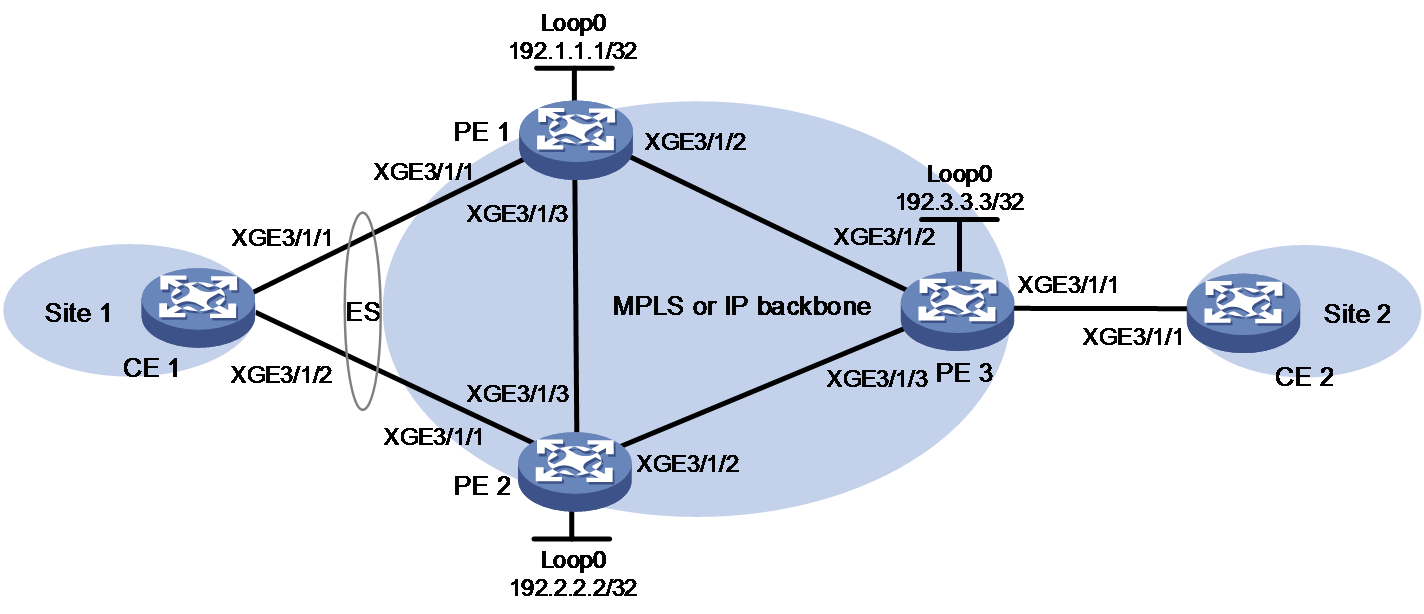
|
Device |
Interface |
IP address |
Device |
Interface |
IP address |
|
PE 1 |
Loop0 |
192.1.1.1/32 |
CE 1 |
RAGG1 |
100.1.1.1/24 |
|
|
XGE3/1/1 |
N/A |
CE 2 |
XGE3/1/1 |
100.1.1.2/24 |
|
|
XGE3/1/2 |
10.1.1.1/24 |
PE 3 |
Loop0 |
192.3.3.3/32 |
|
|
XGE3/1/3 |
10.1.3.1/24 |
|
XGE3/1/1 |
N/A |
|
PE 2 |
Loop0 |
192.2.2.2/32 |
|
XGE3/1/2 |
10.1.1.2/24 |
|
|
XGE3/1/1 |
N/A |
|
XGE3/1/3 |
10.1.2.2/24 |
|
|
XGE3/1/2 |
10.1.2.1/24 |
|
|
|
|
|
XGE3/1/3 |
10.1.3.2/24 |
|
|
|
Procedure
1. Configure CE 1:
# Create dynamic Layer 3 aggregate interface 1 and assign it an IP address.
<CE1> system-view
[CE1] interface route-aggregation 1
[CE1-Route-Aggregation1] ip address 100.1.1.1 24
[CE1-Route-Aggregation1] quit
# Assign Ten-GigabitEthernet 3/1/1 and Ten-GigabitEthernet 3/1/2 to aggregation group 1.
[CE1] interface ten-gigabitethernet 3/1/1
[CE1-Ten-GigabitEthernet3/1/1] port link-aggregation group 1
[CE1-Ten-GigabitEthernet3/1/1] quit
[CE1] interface ten-gigabitethernet 3/1/2
[CE1-Ten-GigabitEthernet3/1/2] port link-aggregation group 1
[CE1-Ten-GigabitEthernet3/1/2] quit
2. Configure PE 1:
# Configure the LSR ID.
<PE1> system-view
[PE1] interface loopback 0
[PE1-LoopBack0] ip address 192.1.1.1 32
[PE1-LoopBack0] quit
[PE1] mpls lsr-id 192.1.1.1
# Enable L2VPN.
[PE1] l2vpn enable
# Enable global LDP.
[PE1] mpls ldp
[PE1-ldp] quit
# Configure Ten-GigabitEthernet 3/1/2 (the interface connected to PE 3), and enable LDP on the interface.
[PE1] interface ten-gigabitethernet 3/1/2
[PE1-Ten-GigabitEthernet3/1/2] ip address 10.1.1.1 24
[PE1-Ten-GigabitEthernet3/1/2] mpls enable
[PE1-Ten-GigabitEthernet3/1/2] mpls ldp enable
[PE1-Ten-GigabitEthernet3/1/2] quit
# Configure OSPF for LDP to create LSPs.
[PE1] ospf
[PE1-ospf-1] area 0
[PE1-ospf-1-area-0.0.0.0] network 10.1.1.0 0.0.0.255
[PE1-ospf-1-area-0.0.0.0] network 10.1.3.0 0.0.0.255
[PE1-ospf-1-area-0.0.0.0] network 192.1.1.1 0.0.0.0
[PE1-ospf-1-area-0.0.0.0] quit
[PE1-ospf-1] quit
# Create IBGP connections to PE 2 and PE 3, and enable BGP to advertise routes to PE 2 and PE 3.
[PE1] bgp 100
[PE1-bgp-default] peer 192.2.2.2 as-number 100
[PE1-bgp-default] peer 192.2.2.2 connect-interface loopback 0
[PE1-bgp-default] peer 192.3.3.3 as-number 100
[PE1-bgp-default] peer 192.3.3.3 connect-interface loopback 0
[PE1-bgp-default] address-family l2vpn evpn
[PE1-bgp-default-evpn] peer 192.2.2.2 enable
[PE1-bgp-default-evpn] peer 192.3.3.3 enable
[PE1-bgp-default-evpn] peer 192.2.2.2 advertise encap-type mpls
[PE1-bgp-default-evpn] peer 192.3.3.3 advertise encap-type mpls
[PE1-bgp-default-evpn] quit
[PE1-bgp-default] quit
# Assign an ESI to Ten-GigabitEthernet 3/1/1 and set its redundancy mode to all-active.
[PE1] interface ten-gigabitethernet 3/1/1
[PE1-Ten-GigabitEthernet3/1/1] esi 1.1.1.1.1
[PE1-Ten-GigabitEthernet3/1/1] evpn redundancy-mode all-active
[PE1-Ten-GigabitEthernet3/1/1] quit
# Create a cross-connect group named vpna, create an EVPN instance for it, and enable MPLS encapsulation. Configure an RD and route targets for the EVPN instance.
[PE1] xconnect-group vpna
[PE1-xcg-vpna] evpn encapsulation mpls
[PE1-xcg-vpna-evpn-mpls] route-distinguisher 1:1
[PE1-xcg-vpna-evpn-mpls] vpn-target 1:1 export-extcommunity
[PE1-xcg-vpna-evpn-mpls] vpn-target 1:1 import-extcommunity
[PE1-xcg-vpna-evpn-mpls] quit
# Create cross-connect pw1 and map Ten-GigabitEthernet 3/1/1 to it. Create an EVPN PW on the cross-connect.
[PE1] xconnect-group vpna
[PE1-xcg-vpna] connection pw1
[PE1-xcg-vpna-pw1] ac interface ten-gigabitethernet 3/1/1
[PE1-xcg-vpna-pw1-Ten-GigabitEthernet3/1/1] quit
[PE1-xcg-vpna-pw1] evpn local-service-id 1 remote-service-id 2
[PE1-xcg-vpna-pw1-1-2] quit
[PE1-xcg-vpna-pw1] quit
[PE1-xcg-vpna] quit
# Associate Ten-GigabitEthernet 3/1/2 with track entry 1.
[PE1] track 1 interface ten-gigabitethernet 3/1/2
[PE1-track-1] quit
# Configure CLI-defined monitor policy 1 to associate Ten-GigabitEthernet 3/1/2 with Ten-GigabitEthernet 3/1/1. This setting allows PE 1 to shut down Ten-GigabitEthernet 3/1/1 when Ten-GigabitEthernet 3/1/2 goes down.
[PE1] rtm cli-policy policy1
[PE1-rtm-policy1] event track 1 state negative
[PE1-rtm-policy1] action 0 cli system-view
[PE1-rtm-policy1] action 1 cli interface ten-gigabitethernet 3/1/1
[PE1-rtm-policy1] action 2 cli shutdown
[PE1-rtm-policy1] user-role network-admin
[PE1-rtm-policy1] quit
3. Configure PE 2:
# Configure the LSR ID.
<PE2> system-view
[PE2] interface loopback 0
[PE2-LoopBack0] ip address 192.2.2.2 32
[PE2-LoopBack0] quit
[PE2] mpls lsr-id 192.2.2.2
# Enable L2VPN.
[PE2] l2vpn enable
# Enable global LDP.
[PE2] mpls ldp
[PE2-ldp] quit
# Configure Ten-GigabitEthernet 3/1/2 (the interface connected to PE 3), and enable LDP on the interface.
[PE2] interface ten-gigabitethernet 3/1/2
[PE2-Ten-GigabitEthernet3/1/2] ip address 10.1.2.1 24
[PE2-Ten-GigabitEthernet3/1/2] mpls enable
[PE2-Ten-GigabitEthernet3/1/2] mpls ldp enable
[PE2-Ten-GigabitEthernet3/1/2] quit
# Configure OSPF for LDP to create LSPs.
[PE2] ospf
[PE2-ospf-1] area 0
[PE2-ospf-1-area-0.0.0.0] network 10.1.2.0 0.0.0.255
[PE2-ospf-1-area-0.0.0.0] network 10.1.3.0 0.0.0.255
[PE2-ospf-1-area-0.0.0.0] network 192.2.2.2 0.0.0.0
[PE2-ospf-1-area-0.0.0.0] quit
[PE2-ospf-1] quit
# Create IBGP connections to PE 1 and PE 3, and enable BGP to advertise routes to PE 1 and PE 3.
[PE2] bgp 100
[PE2-bgp-default] peer 192.1.1.1 as-number 100
[PE2-bgp-default] peer 192.1.1.1 connect-interface loopback 0
[PE2-bgp-default] peer 192.3.3.3 as-number 100
[PE2-bgp-default] peer 192.3.3.3 connect-interface loopback 0
[PE2-bgp-default] address-family l2vpn evpn
[PE2-bgp-default-evpn] peer 192.1.1.1 enable
[PE2-bgp-default-evpn] peer 192.3.3.3 enable
[PE2-bgp-default-evpn] peer 192.1.1.1 advertise encap-type mpls
[PE2-bgp-default-evpn] peer 192.3.3.3 advertise encap-type mpls
[PE2-bgp-default-evpn] quit
[PE2-bgp-default] quit
# Assign an ESI to Ten-GigabitEthernet 3/1/1 and set its redundancy mode to all-active.
[PE2] interface ten-gigabitethernet 3/1/1
[PE2-Ten-GigabitEthernet3/1/1] esi 1.1.1.1.1
[PE2-Ten-GigabitEthernet3/1/1] evpn redundancy-mode all-active
[PE2-Ten-GigabitEthernet3/1/1] quit
# Create a cross-connect group named vpna, create an EVPN instance for it, and enable MPLS encapsulation. Configure an RD and route targets for the EVPN instance.
[PE2] xconnect-group vpna
[PE2-xcg-vpna] evpn encapsulation mpls
[PE2-xcg-vpna-evpn-mpls] route-distinguisher 1:1
[PE2-xcg-vpna-evpn-mpls] vpn-target 1:1 export-extcommunity
[PE2-xcg-vpna-evpn-mpls] vpn-target 1:1 import-extcommunity
[PE2-xcg-vpna-evpn-mpls] quit
# Create cross-connect pw1 and map Ten-GigabitEthernet 3/1/1 to it. Create an EVPN PW on the cross-connect.
[PE2] xconnect-group vpna
[PE2-xcg-vpna] connection pw1
[PE2-xcg-vpna-pw1] ac interface ten-gigabitethernet 3/1/1
[PE2-xcg-vpna-pw1-Ten-GigabitEthernet3/1/1] quit
[PE2-xcg-vpna-pw1] evpn local-service-id 1 remote-service-id 2
[PE2-xcg-vpna-pw1-1-2] quit
[PE2-xcg-vpna-pw1] quit
[PE2-xcg-vpna] quit
# Associate Ten-GigabitEthernet 3/1/2 with track entry 1.
[PE2] track 1 interface ten-gigabitethernet 3/1/2
[PE2-track-1] quit
# Configure CLI-defined monitor policy 1 to associate Ten-GigabitEthernet 3/1/2 with Ten-GigabitEthernet 3/1/1. This setting allows PE 2 to shut down Ten-GigabitEthernet 3/1/1 when Ten-GigabitEthernet 3/1/2 goes down.
[PE2] rtm cli-policy policy1
[PE2-rtm-policy1] event track 1 state negative
[PE2-rtm-policy1] action 0 cli system-view
[PE2-rtm-policy1] action 1 cli interface ten-gigabitethernet 3/1/1
[PE2-rtm-policy1] action 2 cli shutdown
[PE2-rtm-policy1] user-role network-admin
[PE2-rtm-policy1] quit
4. Configure PE 3:
# Configure the LSR ID.
<PE3> system-view
[PE3] interface loopback 0
[PE3-LoopBack0] ip address 192.3.3.3 32
[PE3-LoopBack0] quit
[PE3] mpls lsr-id 192.3.3.3
# Enable L2VPN.
[PE3] l2vpn enable
# Enable global LDP.
[PE3] mpls ldp
[PE3-ldp] quit
# Configure Ten-GigabitEthernet 3/1/2 (the interface connected to PE 1) and Ten-GigabitEthernet 3/1/3 (the interface connected to PE 2), and enable LDP on the interfaces.
[PE3] interface ten-gigabitethernet 3/1/2
[PE3-Ten-GigabitEthernet3/1/2] ip address 10.1.1.2 24
[PE3-Ten-GigabitEthernet3/1/2] mpls enable
[PE3-Ten-GigabitEthernet3/1/2] mpls ldp enable
[PE3-Ten-GigabitEthernet3/1/2] quit
[PE3] interface ten-gigabitethernet 3/1/3
[PE3-Ten-GigabitEthernet3/1/3] ip address 10.1.2.2 24
[PE3-Ten-GigabitEthernet3/1/3] mpls enable
[PE3-Ten-GigabitEthernet3/1/3] mpls ldp enable
[PE3-Ten-GigabitEthernet3/1/3] quit
# Configure OSPF for LDP to create LSPs.
[PE3] ospf
[PE3-ospf-1] area 0
[PE3-ospf-1-area-0.0.0.0] network 192.3.3.3 0.0.0.0
[PE3-ospf-1-area-0.0.0.0] network 10.1.1.0 0.0.0.255
[PE3-ospf-1-area-0.0.0.0] network 10.1.2.0 0.0.0.255
[PE3-ospf-1-area-0.0.0.0] quit
[PE3-ospf-1] quit
# Create IBGP connections to PE 1 and PE 2, and enable BGP to advertise routes to PE 1 and PE 2.
[PE3] bgp 100
[PE3-bgp-default] peer 192.1.1.1 as-number 100
[PE3-bgp-default] peer 192.1.1.1 connect-interface loopback 0
[PE3-bgp-default] peer 192.2.2.2 as-number 100
[PE3-bgp-default] peer 192.2.2.2 connect-interface loopback 0
[PE3-bgp-default] address-family l2vpn evpn
[PE3-bgp-default-evpn] peer 192.1.1.1 enable
[PE3-bgp-default-evpn] peer 192.2.2.2 enable
[PE3-bgp-default-evpn] peer 192.1.1.1 advertise encap-type mpls
[PE3-bgp-default-evpn] peer 192.2.2.2 advertise encap-type mpls
[PE3-bgp-default-evpn] quit
[PE3-bgp-default] quit
# Create a cross-connect group named vpna, create an EVPN instance for it, and enable MPLS encapsulation. Configure an RD and route targets for the EVPN instance.
[PE3] xconnect-group vpna
[PE3-xcg-vpna] evpn encapsulation mpls
[PE3-xcg-vpna-evpn-mpls] route-distinguisher 1:1
[PE3-xcg-vpna-evpn-mpls] vpn-target 1:1 export-extcommunity
[PE3-xcg-vpna-evpn-mpls] vpn-target 1:1 import-extcommunity
[PE3-xcg-vpna-evpn-mpls] quit
# Create cross-connect pw1 and map Ten-GigabitEthernet 3/1/1 to it. Create an EVPN PW on the cross-connect.
[PE3] xconnect-group vpna
[PE3-xcg-vpna] connection pw1
[PE3-xcg-vpna-pw1] ac interface ten-gigabitethernet 3/1/1
[PE3-xcg-vpna-pw1-Ten-GigabitEthernet3/1/1] quit
[PE3-xcg-vpna-pw1] evpn local-service-id 2 remote-service-id 1
[PE3-xcg-vpna-pw1-2-1] quit
[PE3-xcg-vpna-pw1] quit
[PE3-xcg-vpna] quit
5. Configure CE 2.
<CE2> system-view
[CE2] interface ten-gigabitethernet 3/1/1
[CE2-Vlan-interface10] ip address 100.1.1.2 24
[CE2-Vlan-interface10] quit
Verifying the configuration
# Verify that PE 1 has established EVPN PWs to PE 2 and PE 3.
<PE1> display l2vpn pw
Flags: M - main, B - backup, E - ecmp, BY - bypass, H - hub link, S - spoke link
N - no split horizon, A - administration, ABY - ac-bypass
PBY - pw-bypass
Total number of PWs: 1
1 up, 0 blocked, 0 down, 0 defect, 0 idle, 0 duplicate
Xconnect-group Name: vpna
Peer PWID/RmtSite/SrvID In/Out Label Proto Flag Link ID State
192.3.3.3 2 710263/710265 EVPN M 0 Up
# Verify that the EVPN information about the cross-connect on PE 1 is correct.
<PE1> display evpn route xconnect-group
Flags: P - Primary, B - Backup, C - Control word
Xconnect group name: vpna
Connection name: 1
ESI : 0001.0001.0001.0001.0001
Local service ID : 1
Remote service ID : 2
Control word : Disabled
In label : 710263
Local MTU : 1500
AC state : Up
PW type : Ethernet
Nexthop ESI Out label Flags MTU state
192.3.3.3 0000.0000.0000.0000.0000 710265 P 1500 Up
192.2.2.2 0001.0001.0001.0001.0001 710264 P 1500 Up
# Verify that PE 1 has local ES information.
<PE1> display evpn es local
Redundancy mode: A - All-active, S - Single-active
Xconnect-group name : vpna
ESI Tag ID DF address Mode State ESI label
0001.0001.0001.0001.0001 0 192.1.1.1 A Up -
# Verify that PE 1 has remote ES information.
<PE1> display evpn es remote
Control Flags: P - Primary, B - Backup, C - Control word
Xconnect group name : vpna
ESI : 0001.0001.0001.0001.0001
Ethernet segment routes :
192.2.2.2
A-D per ES routes :
Peer IP Remote Redundancy mode
192.2.2.2 All-active
A-D per EVI routes :
Tag ID Peer IP Control Flags
1 192.2.2.2 P
# Verify that PE 2 has established EVPN PWs to PE 1 and PE 3.
<PE2> display l2vpn pw
Flags: M - main, B - backup, E - ecmp, BY - bypass, H - hub link, S - spoke link
N - no split horizon, A - administration, ABY - ac-bypass
PBY - pw-bypass
Total number of PWs: 1
1 up, 0 blocked, 0 down, 0 defect, 0 idle, 0 duplicate
Xconnect-group Name: vpna
Peer PWID/RmtSite/SrvID In/Out Label Proto Flag Link ID State
192.3.3.3 2 710124/710265 EVPN M 1 Up
# Verify that PE 3 has established EVPN PWs to PE 1 and PE 2.
<PE3> display l2vpn pw
Flags: M - main, B - backup, E - ecmp, BY - bypass, H - hub link, S - spoke link
N - no split horizon, A - administration, ABY - ac-bypass
PBY - pw-bypass
Total number of PWs: 2
2 up, 0 blocked, 0 down, 0 defect, 0 idle, 0 duplicate
Xconnect-group Name: vpna
Peer PWID/RmtSite/SrvID In/Out Label Proto Flag Link ID State
192.1.1.1 1 710265/710263 EVPN E 0 Up
192.2.2.2 1 710265/710124 EVPN E 0 Up
# Verify that CE 1 and CE 2 can ping each other when the PW on PE 1 or PE 2 fails. (Details not shown.)
Example: Configuring PW concatenation
Network configuration
As shown in Figure 19:
· Set up an MPLS TE tunnel between each PE and the P device, and configure each MPLS TE tunnel to convey an EVPN PW.
· Concatenate the EVPN PWs on the P device for the CEs to communicate at Layer 2 over the MPLS backbone.
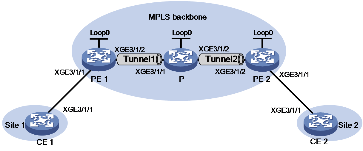
|
Device |
Interface |
IP address |
Device |
Interface |
IP address |
|
CE 1 |
XGE3/1/1 |
100.1.1.1/24 |
P |
Loop0 |
192.4.4.4/32 |
|
PE 1 |
Loop0 |
192.2.2.2/32 |
|
XGE3/1/1 |
23.1.1.2/24 |
|
|
XGE3/1/2 |
23.1.1.1/24 |
|
XGE3/1/2 |
26.2.2.2/24 |
|
CE 2 |
XGE3/1/1 |
100.1.1.2/24 |
PE 2 |
Loop0 |
192.3.3.3/32 |
|
|
|
|
|
XGE3/1/2 |
26.2.2.1/24 |
Procedure
1. Configure CE 1.
<CE1> system-view
[CE1] interface ten-gigabitethernet 3/1/1
[CE1-Ten-GigabitEthernet3/1/1] ip address 100.1.1.1 24
[CE1-Ten-GigabitEthernet3/1/1] quit
2. Configure PE 1:
# Configure the LSR ID.
<PE1> system-view
[PE1] interface loopback 0
[PE1-LoopBack0] ip address 192.2.2.2 32
[PE1-LoopBack0] quit
[PE1] mpls lsr-id 192.2.2.2
# Enable L2VPN.
[PE1] l2vpn enable
# Set up an MPLS TE tunnel between PE 1 and the P device as described in MPLS TE configuration in MPLS Configuration Guide.
# Create a cross-connect group named vpna, create an EVPN instance for it, and enable MPLS encapsulation. Configure an RD and route targets for the EVPN instance.
[PE1] xconnect-group vpna
[PE1-xcg-vpna] evpn encapsulation mpls
[PE1-xcg-vpna-evpn-mpls] route-distinguisher 1:1
[PE1-xcg-vpna-evpn-mpls] vpn-target 1:1 export-extcommunity
[PE1-xcg-vpna-evpn-mpls] vpn-target 1:2 import-extcommunity
[PE1-xcg-vpna-evpn-mpls] quit
# Create cross-connect pw1 and map Ten-GigabitEthernet 3/1/1 to it. Create an EVPN PW on the cross-connect.
[PE1-xcg-vpna] connection pw1
[PE1-xcg-vpna-pw1] evpn local-service-id 2 remote-service-id 1
[PE1-xcg-vpna-pw1-2-1] quit
[PE1-xcg-vpna-pw1] ac interface ten-gigabitethernet 3/1/1
[PE1-xcg-vpna-pw1-Ten-GigabitEthernet3/1/1] quit
[PE1-xcg-vpna-pw1] quit
[PE1-xcg-vpna] quit
# Create an IBGP connection to the P device, and enable BGP to advertise BGP EVPN routes to the P device.
[PE1] bgp 100
[PE1-bgp-default] peer 192.4.4.4 as-number 100
[PE1-bgp-default] peer 192.4.4.4 connect-interface LoopBack0
[PE1-bgp-default] address-family l2vpn evpn
[PE1-bgp-default-evpn] peer 192.4.4.4 enable
[PE1-bgp-default-evpn] peer 192.4.4.4 advertise encap-type mpls
[PE1-bgp-default-evpn] quit
[PE1-bgp-default] quit
3. Configure the P device:
# Configure the LSR ID.
<P> system-view
[P] interface loopback 0
[P-LoopBack0] ip address 192.4.4.4 32
[P-LoopBack0] quit
[P] mpls lsr-id 192.4.4.4
# Enable L2VPN.
[P] l2vpn enable
# Set up an MPLS TE tunnel to each PE as described in MPLS TE configuration in MPLS Configuration Guide.
# Create a cross-connect group named vpna, create an EVPN instance for it, and enable MPLS encapsulation. Configure an RD and route targets for the EVPN instance.
[P] xconnect-group vpna
[P-xcg-vpna] evpn encapsulation mpls
[P-xcg-vpna-evpn-mpls] route-distinguisher 1:1
[P-xcg-vpna-evpn-mpls] vpn-target 1:2 export-extcommunity
[P-xcg-vpna-evpn-mpls] vpn-target 1:1 1:3 import-extcommunity
[P-xcg-vpna-evpn-mpls] quit
# Create cross-connect pw1 and create two EVPN PWs on the cross-connect.
[P-xcg-vpna] connection pw1
[P-xcg-vpna-pw1] evpn local-service-id 1 remote-service-id 2
[P-xcg-vpna-pw1-1-2] quit
[P-xcg-vpna-pw1] evpn local-service-id 3 remote-service-id 4
[P-xcg-vpna-pw1-3-4] quit
[P-xcg-vpna-pw1] quit
[P-xcg-vpna] quit
# Create an IBGP connection to each PE, and enable BGP to advertise BGP EVPN routes to the PEs.
[P] bgp 100
[P-bgp-default] peer 192.2.2.2 as-number 100
[P-bgp-default] peer 192.2.2.2 connect-interface LoopBack0
[P-bgp-default] peer 192.3.3.3 as-number 100
[P-bgp-default] peer 192.3.3.3 connect-interface LoopBack0
[P-bgp-default] address-family l2vpn evpn
[P-bgp-default-evpn] peer 192.2.2.2 enable
[P-bgp-default-evpn] peer 192.3.3.3 enable
[P-bgp-default-evpn] peer 192.2.2.2 advertise encap-type mpls
[P-bgp-default-evpn] peer 192.3.3.3 advertise encap-type mpls
[P-bgp-default-evpn] quit
[P-bgp-default] quit
4. Configure PE 2:
# Configure the LSR ID.
<PE2> system-view
[PE2] interface loopback 0
[PE2-LoopBack0] ip address 192.3.3.3 32
[PE2-LoopBack0] quit
[PE2] mpls lsr-id 192.3.3.3
# Enable L2VPN.
[PE2] l2vpn enable
# Set up an MPLS TE tunnel between PE 2 and the P device as described in MPLS TE configuration in MPLS Configuration Guide.
# Create a cross-connect group named vpna, create an EVPN instance for it, and enable MPLS encapsulation. Configure an RD and route targets for the EVPN instance.
[PE2] xconnect-group vpna
[PE2-xcg-vpna] evpn encapsulation mpls
[PE2-xcg-vpna-evpn-mpls] route-distinguisher 1:1
[PE2-xcg-vpna-evpn-mpls] vpn-target 1:3 export-extcommunity
[PE2-xcg-vpna-evpn-mpls] vpn-target 1:2 import-extcommunity
[PE2-xcg-vpna-evpn-mpls] quit
# Create cross-connect pw1 and map Ten-GigabitEthernet 3/1/1 to it. Create an EVPN PW on the cross-connect.
[PE2-xcg-vpna] connection pw1
[PE2-xcg-vpna-pw1] evpn local-service-id 4 remote-service-id 3
[PE2-xcg-vpna-pw1-4-3] quit
[PE2-xcg-vpna-pw1] ac interface ten-gigabitethernet 3/1/1
[PE2-xcg-vpna-pw1-Ten-GigabitEthernet3/1/1] quit
[PE2-xcg-vpna-pw1] quit
[PE2-xcg-vpna] quit
# Create an IBGP connection to the P device, and enable BGP to advertise BGP EVPN routes to the P device.
[PE2] bgp 100
[PE2-bgp-default] peer 192.4.4.4 as-number 100
[PE2-bgp-default] peer 192.4.4.4 connect-interface LoopBack0
[PE2-bgp-default] address-family l2vpn evpn
[PE2-bgp-default-evpn] peer 192.4.4.4 enable
[PE2-bgp-default-evpn] peer 192.4.4.4 advertise encap-type mpls
[PE2-bgp-default-evpn] quit
[PE2-bgp-default] quit
5. Configure CE 2.
<CE2> system-view
[CE2] interface ten-gigabitethernet 3/1/1
[CE2-Ten-GigabitEthernet3/1/1] ip address 100.1.1.2 24
[CE2-Ten-GigabitEthernet3/1/1] quit
Verifying the configuration
# Verify that an EVPN PW has been established on PE 1.
[PE1] display l2vpn pw
Flags: M - main, B - backup, E - ecmp, BY - bypass, H - hub link, S - spoke link
N - no split horizon, A - administration, ABY - ac-bypass
PBY - pw-bypass
Total number of PWs: 1
1 up, 0 blocked, 0 down, 0 defect, 0 idle, 0 duplicate
Xconnect-group Name: vpna
Peer PWID/RmtSite/SrvID In/Out Label Proto Flag Link ID State
192.4.4.4 1 1151/1150 EVPN M 0 Up
# Verify that two EVPN PWs are concatenated on the P device.
[P] display l2vpn pw
Flags: M - main, B - backup, E - ecmp, BY - bypass, H - hub link, S - spoke link
N - no split horizon, A - administration, ABY - ac-bypass
PBY - pw-bypass
Total number of PWs: 2
2 up, 0 blocked, 0 down, 0 defect, 0 idle, 0 duplicate
Xconnect-group Name: vpna
Peer PWID/RmtSite/SrvID In/Out Label Proto Flag Link ID State
192.2.2.2 2 1150/1151 EVPN M 0 Up
192.3.3.3 4 1151/1151 EVPN M 1 Up
# Verify that an EVPN PW has been established on PE 2.
[PE2] display l2vpn pw
Flags: M - main, B - backup, E - ecmp, BY - bypass, H - hub link, S - spoke link
N - no split horizon, A - administration, ABY - ac-bypass
PBY - pw-bypass
Total number of PWs: 1
1 up, 0 blocked, 0 down, 0 defect, 0 idle, 0 duplicate
Xconnect-group Name: vpn1a
Peer PWID/RmtSite/SrvID In/Out Label Proto Flag Link ID State
192.4.4.4 3 1151/1151 EVPN M 0 Up
# Verify that CE 1 and CE 2 can ping each other. (Details not shown.)
Example: Configuring inter-AS option A
Network configuration
As shown in Figure 20:
· Establish an EVPN PW between the PE and the ASBR in each AS.
· Associate Ten-GigabitEthernet 3/1/1 with the EVPN PW on each ASBR.
· Associate Ten-GigabitEthernet 3/1/1 with the EVPN PW on each PE.
· Run OSPF on the MPLS backbone of each AS.

|
Device |
Interface |
IP address |
Device |
Interface |
IP address |
|
CE 1 |
XGE3/1/1 |
100.1.1.1/24 |
ASBR 1 |
Loop0 |
192.2.2.2/32 |
|
PE 1 |
Loop0 |
192.1.1.1/32 |
|
XGE3/1/2 |
23.1.1.2/24 |
|
|
XGE3/1/2 |
23.1.1.1/24 |
|
XGE3/1/1 |
26.2.2.2/24 |
|
PE 2 |
Loop0 |
192.4.4.4/32 |
ASBR 2 |
Loop0 |
192.3.3.3/32 |
|
|
XGE3/1/2 |
22.2.2.1/24 |
|
XGE3/1/1 |
26.2.2.3/24 |
|
CE 2 |
XGE3/1/1 |
100.1.1.2/24 |
|
XGE3/1/2 |
22.2.2.3/24 |
Procedure
1. Configure CE 1.
<CE1> system-view
[CE1] interface ten-gigabitethernet 3/1/1
[CE1-Ten-GigabitEthernet3/1/1] ip address 100.1.1.1 24
[CE1-Ten-GigabitEthernet3/1/1] quit
2. Configure PE 1:
# Configure the LSR ID.
<PE1> system-view
[PE1] interface loopback 0
[PE1-LoopBack0] ip address 192.1.1.1 32
[PE1-LoopBack0] quit
[PE1] mpls lsr-id 192.1.1.1
# Enable L2VPN.
[PE1] l2vpn enable
# Enable global LDP.
[PE1] mpls ldp
[PE1-ldp] quit
# Enable LDP on Ten-GigabitEthernet 3/1/2, the interface connected to ASBR 1.
[PE1] interface ten-gigabitethernet 3/1/2
[PE1-Ten-GigabitEthernet3/1/2] ip address 23.1.1.1 24
[PE1-Ten-GigabitEthernet3/1/2] mpls enable
[PE1-Ten-GigabitEthernet3/1/2] mpls ldp enable
[PE1-Ten-GigabitEthernet3/1/2] quit
# Configure OSPF for LDP to create LSPs.
[PE1] ospf
[PE1-ospf-1] area 0
[PE1-ospf-1-area-0.0.0.0] network 23.1.1.0 0.0.0.255
[PE1-ospf-1-area-0.0.0.0] network 192.1.1.1 0.0.0.0
[PE1-ospf-1-area-0.0.0.0] quit
[PE1-ospf-1] quit
# Create a cross-connect group named vpna, create an EVPN instance for it, and enable MPLS encapsulation. Configure an RD and route targets for the EVPN instance.
[PE1] xconnect-group vpna
[PE1-xcg-vpna] evpn encapsulation mpls
[PE1-xcg-vpna-evpn-mpls] route-distinguisher 1:1
[PE1-xcg-vpna-evpn-mpls] vpn-target 1:1 export-extcommunity
[PE1-xcg-vpna-evpn-mpls] vpn-target 1:2 import-extcommunity
[PE1-xcg-vpna-evpn-mpls] quit
# Create cross-connect pw1 and map Ten-GigabitEthernet 3/1/1 to it. Create an EVPN PW on the cross-connect.
[PE1-xcg-vpna] connection pw1
[PE1-xcg-vpna-pw1] evpn local-service-id 2 remote-service-id 1
[PE1-xcg-vpna-pw1-2-1] quit
[PE1-xcg-vpna-pw1] ac interface ten-gigabitethernet 3/1/1
[PE1-xcg-vpna-pw1-Ten-GigabitEthernet3/1/1] quit
[PE1-xcg-vpna-pw1] quit
[PE1-xcg-vpna] quit
# Create an IBGP connection to ASBR 1, and enable BGP to advertise BGP EVPN routes to ASBR 1.
[PE1] bgp 100
[PE1-bgp-default] peer 192.2.2.2 as-number 100
[PE1-bgp-default] peer 192.2.2.2 connect-interface LoopBack0
[PE1-bgp-default] address-family l2vpn evpn
[PE1-bgp-default-evpn] peer 192.2.2.2 enable
[PE1-bgp-default-evpn] peer 192.2.2.2 advertise encap-type mpls
[PE1-bgp-default-evpn] quit
[PE1-bgp-default] quit
3. Configure ASBR 1:
# Configure the LSR ID.
<ASBR1> system-view
[ASBR1] interface loopback 0
[ASBR1-LoopBack0] ip address 192.2.2.2 32
[ASBR1-LoopBack0] quit
[ASBR1] mpls lsr-id 192.2.2.2
# Enable L2VPN.
[ASBR1] l2vpn enable
# Enable global LDP.
[ASBR1] mpls ldp
[ASBR1-ldp] quit
# Enable LDP on Ten-GigabitEthernet 3/1/2, the interface connected to PE 1.
[ASBR1] interface ten-gigabitethernet 3/1/2
[ASBR1-Ten-GigabitEthernet3/1/2] ip address 23.1.1.2 24
[ASBR1-Ten-GigabitEthernet3/1/2] mpls enable
[ASBR1-Ten-GigabitEthernet3/1/2] mpls ldp enable
[ASBR1-Ten-GigabitEthernet3/1/2] quit
# Configure OSPF for LDP to create LSPs.
[ASBR1] ospf
[ASBR1-ospf-1] area 0
[ASBR1-ospf-1-area-0.0.0.0] network 23.1.1.0 0.0.0.255
[ASBR1-ospf-1-area-0.0.0.0] network 192.2.2.2 0.0.0.0
[ASBR1-ospf-1-area-0.0.0.0] quit
[ASBR1-ospf-1] quit
# Create a cross-connect group named vpna, create an EVPN instance for it, and enable MPLS encapsulation. Configure an RD and route targets for the EVPN instance.
[ASBR1] xconnect-group vpna
[ASBR1-xcg-vpna] evpn encapsulation mpls
[ASBR1-xcg-vpna-evpn-mpls] route-distinguisher 1:1
[ASBR1-xcg-vpna-evpn-mpls] vpn-target 1:2 export-extcommunity
[ASBR1-xcg-vpna-evpn-mpls] vpn-target 1:1 import-extcommunity
[ASBR1-xcg-vpna-evpn-mpls] quit
# Create cross-connect pw1 and map Ten-GigabitEthernet 3/1/1 (the interface connected to ASBR 2) to it. Create an EVPN PW on the cross-connect.
[ASBR1-xcg-vpna] connection pw1
[ASBR1-xcg-vpna-pw1] evpn local-service-id 1 remote-service-id 2
[ASBR1-xcg-vpna-pw1-1-2] quit
[ASBR1-xcg-vpna-pw1] ac interface ten-gigabitethernet 3/1/1
[ASBR1-xcg-vpna-pw1-Ten-GigabitEthernet3/1/1] quit
[ASBR1-xcg-vpna-pw1] quit
[ASBR1-xcg-vpna] quit
# Create an IBGP connection to PE 1, and enable BGP to advertise BGP EVPN routes to PE 1.
[ASBR1] bgp 100
[ASBR1-bgp-default] peer 192.1.1.1 as-number 100
[ASBR1-bgp-default] peer 192.1.1.1 connect-interface LoopBack0
[ASBR1-bgp-default] address-family l2vpn evpn
[ASBR1-bgp-default-evpn] peer 192.1.1.1 enable
[ASBR1-bgp-default-evpn] peer 192.1.1.1 advertise encap-type mpls
[ASBR1-bgp-default-evpn] quit
[ASBR1-bgp-default] quit
4. Configure ASBR 2:
# Configure the LSR ID.
<ASBR2> system-view
[ASBR2] interface loopback 0
[ASBR2-LoopBack0] ip address 192.3.3.3 32
[ASBR2-LoopBack0] quit
[ASBR2] mpls lsr-id 192.3.3.3
# Enable L2VPN.
[ASBR2] l2vpn enable
# Enable global LDP.
[ASBR2] mpls ldp
[ASBR2-ldp] quit
# Enable LDP on Ten-GigabitEthernet 3/1/2, the interface connected to PE 2.
[ASBR2] interface ten-gigabitethernet 3/1/2
[ASBR2-Ten-GigabitEthernet3/1/2] ip address 22.2.2.3 24
[ASBR2-Ten-GigabitEthernet3/1/2] mpls enable
[ASBR2-Ten-GigabitEthernet3/1/2] mpls ldp enable
[ASBR2-Ten-GigabitEthernet3/1/2] quit
# Configure OSPF for LDP to create LSPs.
[ASBR2] ospf
[ASBR2-ospf-1] area 0
[ASBR2-ospf-1-area-0.0.0.0] network 22.2.2.0 0.0.0.255
[ASBR2-ospf-1-area-0.0.0.0] network 192.3.3.3 0.0.0.0
[ASBR2-ospf-1-area-0.0.0.0] quit
[ASBR2-ospf-1] quit
# Create a cross-connect group named vpna, create an EVPN instance for it, and enable MPLS encapsulation. Configure an RD and route targets for the EVPN instance.
[ASBR2] xconnect-group vpna
[ASBR2-xcg-vpna] evpn encapsulation mpls
[ASBR2-xcg-vpna-evpn-mpls] route-distinguisher 1:1
[ASBR2-xcg-vpna-evpn-mpls] vpn-target 2:2 export-extcommunity
[ASBR2-xcg-vpna-evpn-mpls] vpn-target 2:1 import-extcommunity
[ASBR2-xcg-vpna-evpn-mpls] quit
# Create cross-connect pw1 and map Ten-GigabitEthernet 3/1/1 (the interface connected to ASBR 1) to it. Create an EVPN PW on the cross-connect.
[ASBR2-xcg-vpna] connection pw1
[ASBR2-xcg-vpna-pw1] evpn local-service-id 3 remote-service-id 4
[ASBR2-xcg-vpna-pw1-3-4] quit
[ASBR2-xcg-vpna-pw1] ac interface ten-gigabitethernet 3/1/1
[ASBR2-xcg-vpna-pw1-Ten-GigabitEthernet3/1/1] quit
[ASBR2-xcg-vpna-pw1] quit
[ASBR2-xcg-vpna] quit
# Create an IBGP connection to PE 2, and enable BGP to advertise BGP EVPN routes to PE 2.
[ASBR2] bgp 200
[ASBR2-bgp-default] peer 192.4.4.4 as-number 200
[ASBR2-bgp-default] peer 192.4.4.4 connect-interface LoopBack0
[ASBR2-bgp-default] address-family l2vpn evpn
[ASBR2-bgp-default-evpn] peer 192.4.4.4 enable
[ASBR2-bgp-default-evpn] peer 192.4.4.4 advertise encap-type mpls
[ASBR2-bgp-default-evpn] quit
[ASBR2-bgp-default] quit
5. Configure PE 2:
# Configure the LSR ID.
<PE2> system-view
[PE2] interface loopback 0
[PE2-LoopBack0] ip address 192.4.4.4 32
[PE2-LoopBack0] quit
[PE2] mpls lsr-id 192.4.4.4
# Enable L2VPN.
[PE2] l2vpn enable
# Enable global LDP.
[PE2] mpls ldp
[PE2-ldp] quit
# Enable LDP on Ten-GigabitEthernet 3/1/2, the interface connected to ASBR 2.
[PE2] interface ten-gigabitethernet 3/1/2
[PE2-Ten-GigabitEthernet3/1/2] ip address 22.2.2.1 24
[PE2-Ten-GigabitEthernet3/1/2] mpls enable
[PE2-Ten-GigabitEthernet3/1/2] mpls ldp enable
[PE2-Ten-GigabitEthernet3/1/2] quit
# Configure OSPF for LDP to create LSPs.
[PE2] ospf
[PE2-ospf-1] area 0
[PE2-ospf-1-area-0.0.0.0] network 192.4.4.4 0.0.0.0
[PE2-ospf-1-area-0.0.0.0] network 22.2.2.0 0.0.0.255
[PE2-ospf-1-area-0.0.0.0] quit
[PE2-ospf-1] quit
# Create a cross-connect group named vpna, create an EVPN instance for it, and enable MPLS encapsulation. Configure an RD and route targets for the EVPN instance.
[PE2] xconnect-group vpna
[PE2-xcg-vpna] evpn encapsulation mpls
[PE2-xcg-vpna-evpn-mpls] route-distinguisher 1:1
[PE2-xcg-vpna-evpn-mpls] vpn-target 2:1 export-extcommunity
[PE2-xcg-vpna-evpn-mpls] vpn-target 2:2 import-extcommunity
[PE2-xcg-vpna-evpn-mpls] quit
# Create cross-connect pw1 and map Ten-GigabitEthernet 3/1/1 to it. Create an EVPN PW on the cross-connect.
[PE2-xcg-vpna] connection pw1
[PE2-xcg-vpna-pw1] evpn local-service-id 4 remote-service-id 3
[PE2-xcg-vpna-pw1-4-3] quit
[PE2-xcg-vpna-pw1] ac interface ten-gigabitethernet 3/1/1
[PE2-xcg-vpna-pw1-Ten-GigabitEthernet3/1/1] quit
[PE2-xcg-vpna-pw1] quit
[PE2-xcg-vpna] quit
# Create an IBGP connection to ASBR 2, and enable BGP to advertise BGP EVPN routes to ASBR 2.
[PE2] bgp 200
[PE2-bgp-default] peer 192.3.3.3 as-number 200
[PE2-bgp-default] peer 192.3.3.3 connect-interface LoopBack0
[PE2-bgp-default] address-family l2vpn evpn
[PE2-bgp-default-evpn] peer 192.3.3.3 enable
[PE2-bgp-default-evpn] peer 192.3.3.3 advertise encap-type mpls
[PE2-bgp-default-evpn] quit
[PE2-bgp-default] quit
6. Configure CE 2.
<CE2> system-view
[CE2] interface ten-gigabitethernet 3/1/1
[CE2-Ten-GigabitEthernet3/1/1] ip address 100.1.1.2 24
[CE2-Ten-GigabitEthernet3/1/1] quit
Verifying the configuration
# Verify that an EVPN PW has been established on PE 1.
[PE1] display l2vpn pw
Flags: M - main, B - backup, E - ecmp, BY - bypass, H - hub link, S - spoke link
N - no split horizon, A - administration, ABY - ac-bypass
PBY - pw-bypass
Total number of PWs: 1
1 up, 0 blocked, 0 down, 0 defect, 0 idle, 0 duplicate
Xconnect-group Name: vpna
Peer PWID/RmtSite/SrvID In/Out Label Proto Flag Link ID State
192.2.2.2 1 710127/710126 EVPN M 0 Up
# Verify that an EVPN PW has been established on ASBR 1.
[ASBR1] display l2vpn pw
Flags: M - main, B - backup, E - ecmp, BY - bypass, H - hub link, S - spoke link
N - no split horizon, A - administration, ABY - ac-bypass
PBY - pw-bypass
Total number of PWs: 2
2 up, 0 blocked, 0 down, 0 defect, 0 idle, 0 duplicate
Xconnect-group Name: vpn1
Peer PWID/RmtSite/SrvID In/Out Label Proto Flag Link ID State
192.1.1.1 2 710126/710127 EVPN M 0 Up
# Verify that an EVPN PW has been established on ASBR 2.
[ASBR2] display l2vpn pw
Flags: M - main, B - backup, E - ecmp, BY - bypass, H - hub link, S - spoke link
N - no split horizon, A - administration, ABY - ac-bypass
PBY - pw-bypass
Total number of PWs: 2
2 up, 0 blocked, 0 down, 0 defect, 0 idle, 0 duplicate
Xconnect-group Name: vpna
Peer PWID/RmtSite/SrvID In/Out Label Proto Flag Link ID State
192.4.4.4 4 710127/710127 EVPN M 1 Up
# Verify that an EVPN PW has been established on PE 2.
[PE2] display l2vpn pw
Flags: M - main, B - backup, E - ecmp, BY - bypass, H - hub link, S - spoke link
N - no split horizon, A - administration, ABY - ac-bypass
PBY - pw-bypass
Total number of PWs: 1
1 up, 0 blocked, 0 down, 0 defect, 0 idle, 0 duplicate
Xconnect-group Name: vpna
Peer PWID/RmtSite/SrvID In/Out Label Proto Flag Link ID State
192.3.3.3 3 710127/710127 EVPN M 0 Up
# Verify that CE 1 and CE 2 can ping each other. (Details not shown.)
Example: Configuring inter-AS option B
Network configuration
As shown in Figure 21:
· Establish an EVPN PW between the PE and the ASBR in each AS, and use LDP to establish the public tunnels that convey the EVPN PWs.
· Establish an EVPN PW between the ASBRs, and configure BGP to advertise labeled IPv4 unicast routes to establish the public tunnel that conveys the EVPN PW.
· Concatenate the EVPN PWs on the ASBRs.

|
Device |
Interface |
IP address |
Device |
Interface |
IP address |
|
CE 1 |
XGE3/1/1 |
100.1.1.1/24 |
ASBR 1 |
Loop0 |
192.2.2.2/32 |
|
PE 1 |
Loop0 |
192.1.1.1/32 |
|
XGE3/1/2 |
23.1.1.2/24 |
|
|
XGE3/1/2 |
23.1.1.1/24 |
|
XGE3/1/1 |
26.2.2.2/24 |
|
PE 2 |
Loop0 |
192.4.4.4/32 |
ASBR 2 |
Loop0 |
192.3.3.3/32 |
|
|
XGE3/1/2 |
22.2.2.1/24 |
|
XGE3/1/1 |
26.2.2.3/24 |
|
CE 2 |
XGE3/1/1 |
100.1.1.2/24 |
|
XGE3/1/2 |
22.2.2.3/24 |
Procedure
1. Configure CE 1.
<CE1> system-view
[CE1] interface ten-gigabitethernet 3/1/1
[CE1-Ten-GigabitEthernet3/1/1] ip address 100.1.1.1 24
[CE1-Ten-GigabitEthernet3/1/1] quit
2. Configure PE 1:
# Configure the LSR ID.
<PE1> system-view
[PE1] interface loopback 0
[PE1-LoopBack0] ip address 192.1.1.1 32
[PE1-LoopBack0] quit
[PE1] mpls lsr-id 192.1.1.1
# Enable L2VPN.
[PE1] l2vpn enable
# Enable global LDP.
[PE1] mpls ldp
[PE1-ldp] quit
# Enable LDP on Ten-GigabitEthernet 3/1/2, the interface connected to ASBR 1.
[PE1] interface ten-gigabitethernet 3/1/2
[PE1-Ten-GigabitEthernet3/1/2] ip address 23.1.1.1 24
[PE1-Ten-GigabitEthernet3/1/2] mpls enable
[PE1-Ten-GigabitEthernet3/1/2] mpls ldp enable
[PE1-Ten-GigabitEthernet3/1/2] quit
# Configure OSPF for LDP to create LSPs.
[PE1] ospf
[PE1-ospf-1] area 0
[PE1-ospf-1-area-0.0.0.0] network 23.1.1.0 0.0.0.255
[PE1-ospf-1-area-0.0.0.0] network 192.1.1.1 0.0.0.0
[PE1-ospf-1-area-0.0.0.0] quit
[PE1-ospf-1] quit
# Create a cross-connect group named vpna, create an EVPN instance for it, and enable MPLS encapsulation. Configure an RD and route targets for the EVPN instance.
[PE1] xconnect-group vpna
[PE1-xcg-vpna] evpn encapsulation mpls
[PE1-xcg-vpna-evpn-mpls] route-distinguisher 1:1
[PE1-xcg-vpna-evpn-mpls] vpn-target 1:1 export-extcommunity
[PE1-xcg-vpna-evpn-mpls] vpn-target 1:2 import-extcommunity
[PE1-xcg-vpna-evpn-mpls] quit
# Create cross-connect pw1 and map Ten-GigabitEthernet 3/1/1 to it. Create an EVPN PW on the cross-connect.
[PE1-xcg-vpna] connection pw1
[PE1-xcg-vpna-pw1] evpn local-service-id 2 remote-service-id 1
[PE1-xcg-vpna-pw1-2-1] quit
[PE1-xcg-vpna-pw1] ac interface ten-gigabitethernet 3/1/1
[PE1-xcg-vpna-pw1-Ten-GigabitEthernet3/1/1] quit
[PE1-xcg-vpna-pw1] quit
[PE1-xcg-vpna] quit
# Create an IBGP connection to ASBR 1, and enable BGP to advertise BGP EVPN routes to ASBR 1.
[PE1] bgp 100
[PE1-bgp-default] peer 192.2.2.2 as-number 100
[PE1-bgp-default] peer 192.2.2.2 connect-interface LoopBack0
[PE1-bgp-default] address-family l2vpn evpn
[PE1-bgp-default-evpn] peer 192.2.2.2 enable
[PE1-bgp-default-evpn] peer 192.2.2.2 advertise encap-type mpls
[PE1-bgp-default-evpn] quit
[PE1-bgp-default] quit
3. Configure ASBR 1:
# Configure the LSR ID.
<ASBR1> system-view
[ASBR1] interface loopback 0
[ASBR1-LoopBack0] ip address 192.2.2.2 32
[ASBR1-LoopBack0] quit
[ASBR1] mpls lsr-id 192.2.2.2
# Enable L2VPN.
[ASBR1] l2vpn enable
# Enable global LDP.
[ASBR1] mpls ldp
[ASBR1-ldp] quit
# Enable LDP on Ten-GigabitEthernet 3/1/2, the interface connected to PE 1.
[ASBR1] interface ten-gigabitethernet 3/1/2
[ASBR1-Ten-GigabitEthernet3/1/2] ip address 23.1.1.2 24
[ASBR1-Ten-GigabitEthernet3/1/2] mpls enable
[ASBR1-Ten-GigabitEthernet3/1/2] mpls ldp enable
[ASBR1-Ten-GigabitEthernet3/1/2] quit
# Enable MPLS on Ten-GigabitEthernet 3/1/1, the interface connected to ASBR 2.
[ASBR1] interface ten-gigabitethernet 3/1/1
[ASBR1-Ten-GigabitEthernet3/1/1] ip address 26.2.2.2 24
[ASBR1-Ten-GigabitEthernet3/1/1] mpls enable
[ASBR1-Ten-GigabitEthernet3/1/1] quit
# Configure OSPF for LDP to create LSPs.
[ASBR1] ospf
[ASBR1-ospf-1] area 0
[ASBR1-ospf-1-area-0.0.0.0] network 23.1.1.0 0.0.0.255
[ASBR1-ospf-1-area-0.0.0.0] network 192.2.2.2 0.0.0.0
[ASBR1-ospf-1-area-0.0.0.0] quit
[ASBR1-ospf-1] quit
# Create an IBGP connection to PE 1, and enable BGP to advertise BGP EVPN routes to PE 1.
[ASBR1] bgp 100
[ASBR1-bgp-default] peer 192.1.1.1 as-number 100
[ASBR1-bgp-default] peer 192.1.1.1 connect-interface LoopBack0
[ASBR1-bgp-default] address-family l2vpn evpn
[ASBR1-bgp-default-evpn] peer 192.1.1.1 enable
[ASBR1-bgp-default-evpn] peer 192.1.1.1 advertise encap-type mpls
[ASBR1-bgp-default-evpn] quit
# Create an EBGP connection to ASBR 2, and enable BGP to advertise BGP EVPN routes and labeled unicast routes to ASBR 2.
[ASBR1-bgp-default] peer 26.2.2.3 as-number 200
[ASBR1-bgp-default] address-family ipv4 unicast
[ASBR1-bgp-default-ipv4] import-route direct
[ASBR1-bgp-default-ipv4] peer 26.2.2.3 enable
[ASBR1-bgp-default-ipv4] peer 26.2.2.3 route-policy policy1 export
[ASBR1-bgp-default-ipv4] peer 26.2.2.3 label-route-capability
[ASBR1-bgp-default] address-family l2vpn evpn
[ASBR1-bgp-default-evpn] peer 26.2.2.3 enable
[ASBR1-bgp-default-evpn] peer 26.2.2.3 advertise encap-type mpls
[ASBR1-bgp-default-evpn] quit
[ASBR1-bgp-default] quit
[ASBR1] route-policy policy1 permit node 1
[ASBR1-route-policy-policy1-1] apply mpls-label
[ASBR1-route-policy-policy1-1] quit
# Create a cross-connect group named vpna, create an EVPN instance for it, and enable MPLS encapsulation. Configure an RD and route targets for the EVPN instance.
[ASBR1] xconnect-group vpna
[ASBR1-xcg-vpna] evpn encapsulation mpls
[ASBR1-xcg-vpna-evpn-mpls] route-distinguisher 1:1
[ASBR1-xcg-vpna-evpn-mpls] vpn-target 1:2 export-extcommunity
[ASBR1-xcg-vpna-evpn-mpls] vpn-target 1:1 2:2 import-extcommunity
[ASBR1-xcg-vpna-evpn-mpls] quit
# Create cross-connect pw1 and create two EVPN PWs on the cross-connect.
[ASBR1-xcg-vpna] connection pw1
[ASBR1-xcg-vpna-pw1] evpn local-service-id 1 remote-service-id 2
[ASBR1-xcg-vpna-pw1-1-2] quit
[ASBR1-xcg-vpna-pw1] evpn local-service-id 3 remote-service-id 4
[ASBR1-xcg-vpna-pw1-3-4] quit
[ASBR1-xcg-vpna-pw1] quit
[ASBR1-xcg-vpna] quit
4. Configure ASBR 2:
# Configure the LSR ID.
<ASBR2> system-view
[ASBR2] interface loopback 0
[ASBR2-LoopBack0] ip address 192.3.3.3 32
[ASBR2-LoopBack0] quit
[ASBR2] mpls lsr-id 192.3.3.3
# Enable L2VPN.
[ASBR2] l2vpn enable
# Enable global LDP.
[ASBR2] mpls ldp
[ASBR2-ldp] quit
# Enable LDP on Ten-GigabitEthernet 3/1/2, the interface connected to PE 2.
[ASBR2] interface ten-gigabitethernet 3/1/2
[ASBR2-Ten-GigabitEthernet3/1/2] ip address 22.2.2.3 24
[ASBR2-Ten-GigabitEthernet3/1/2] mpls enable
[ASBR2-Ten-GigabitEthernet3/1/2] mpls ldp enable
[ASBR2-Ten-GigabitEthernet3/1/2] quit
# Enable MPLS on Ten-GigabitEthernet 3/1/1, the interface connected to ASBR 1.
[ASBR2] interface ten-gigabitethernet 3/1/1
[ASBR2-Ten-GigabitEthernet3/1/1] ip address 26.2.2.3 24
[ASBR2-Ten-GigabitEthernet3/1/1] mpls enable
[ASBR2-Ten-GigabitEthernet3/1/1] quit
# Configure OSPF for LDP to create LSPs.
[ASBR2] ospf
[ASBR2-ospf-1] area 0
[ASBR2-ospf-1-area-0.0.0.0] network 22.2.2.0 0.0.0.255
[ASBR2-ospf-1-area-0.0.0.0] network 192.3.3.3 0.0.0.0
[ASBR2-ospf-1-area-0.0.0.0] quit
[ASBR2-ospf-1] quit
# Create an IBGP connection to PE 2, and enable BGP to advertise BGP EVPN routes to PE 2.
[ASBR2] bgp 200
[ASBR2-bgp-default] peer 192.4.4.4 as-number 200
[ASBR2-bgp-default] peer 192.4.4.4 connect-interface LoopBack0
[ASBR2-bgp-default] address-family l2vpn evpn
[ASBR2-bgp-default-evpn] peer 192.4.4.4 enable
[ASBR2-bgp-default-evpn] peer 192.4.4.4 advertise encap-type mpls
[ASBR2-bgp-default-evpn] quit
# Create an EBGP connection to ASBR 1, and enable BGP to advertise BGP EVPN routes and labeled unicast routes to ASBR 1.
[ASBR2-bgp-default] peer 26.2.2.2 as-number 100
[ASBR2-bgp-default] address-family ipv4 unicast
[ASBR2-bgp-default-ipv4] import-route direct
[ASBR2-bgp-default-ipv4] peer 26.2.2.2 enable
[ASBR2-bgp-default-ipv4] peer 26.2.2.2 route-policy policy1 export
[ASBR2-bgp-default-ipv4] peer 26.2.2.2 label-route-capability
[ASBR2-bgp-default-ipv4] quit
[ASBR2-bgp-default] address-family l2vpn evpn
[ASBR2-bgp-default-evpn] peer 26.2.2.2 enable
[ASBR2-bgp-default-evpn] peer 26.2.2.2 advertise encap-type mpls
[ASBR2-bgp-default-evpn] quit
[ASBR2-bgp-default] quit
[ASBR2] route-policy policy1 permit node 1
[ASBR2-route-policy-policy1-1] apply mpls-label
[ASBR2-route-policy-policy1-1] quit
# Create a cross-connect group named vpna, create an EVPN instance for it, and enable MPLS encapsulation. Configure an RD and route targets for the EVPN instance.
[ASBR2] xconnect-group vpna
[ASBR2-xcg-vpna] evpn encapsulation mpls
[ASBR2-xcg-vpna-evpn-mpls] route-distinguisher 1:1
[ASBR2-xcg-vpna-evpn-mpls] vpn-target 2:2 export-extcommunity
[ASBR2-xcg-vpna-evpn-mpls] vpn-target 1:2 2:1 import-extcommunity
[ASBR2-xcg-vpna-evpn-mpls] quit
# Create cross-connect pw1 and create two EVPN PWs on the cross-connect.
[ASBR2-xcg-vpna] connection pw1
[ASBR2-xcg-vpna-pw1] evpn local-service-id 4 remote-service-id 3
[ASBR2-xcg-vpna-pw1-4-3] quit
[ASBR2-xcg-vpna-pw1] evpn local-service-id 5 remote-service-id 6
[ASBR2-xcg-vpna-pw1-5-6] quit
[ASBR2-xcg-vpna-pw1] quit
[ASBR2-xcg-vpna] quit
5. Configure PE 2:
# Configure the LSR ID.
<PE2> system-view
[PE2] interface loopback 0
[PE2-LoopBack0] ip address 192.4.4.4 32
[PE2-LoopBack0] quit
[PE2] mpls lsr-id 192.4.4.4
# Enable L2VPN.
[PE2] l2vpn enable
# Enable global LDP.
[PE2] mpls ldp
[PE2-ldp] quit
# Enable LDP on Ten-GigabitEthernet 3/1/2, the interface connected to ASBR 2.
[PE2] interface ten-gigabitethernet 3/1/2
[PE2-Ten-GigabitEthernet3/1/2] ip address 22.2.2.1 24
[PE2-Ten-GigabitEthernet3/1/2] mpls enable
[PE2-Ten-GigabitEthernet3/1/2] mpls ldp enable
[PE2-Ten-GigabitEthernet3/1/2] quit
# Configure OSPF for LDP to create LSPs.
[PE2] ospf
[PE2-ospf-1] area 0
[PE2-ospf-1-area-0.0.0.0] network 192.4.4.4 0.0.0.0
[PE2-ospf-1-area-0.0.0.0] network 22.2.2.0 0.0.0.255
[PE2-ospf-1-area-0.0.0.0] quit
[PE2-ospf-1] quit
# Create a cross-connect group named vpna, create an EVPN instance for it, and enable MPLS encapsulation. Configure an RD and route targets for the EVPN instance.
[PE2] xconnect-group vpna
[PE2-xcg-vpna] evpn encapsulation mpls
[PE2-xcg-vpna-evpn-mpls] route-distinguisher 1:1
[PE2-xcg-vpna-evpn-mpls] vpn-target 2:1 export-extcommunity
[PE2-xcg-vpna-evpn-mpls] vpn-target 2:2 import-extcommunity
[PE2-xcg-vpna-evpn-mpls] quit
# Create cross-connect pw1 and map Ten-GigabitEthernet 3/1/1 to it. Create an EVPN PW on the cross-connect.
[PE2-xcg-vpna] connection pw1
[PE2-xcg-vpna-pw1] evpn local-service-id 6 remote-service-id 5
[PE2-xcg-vpna-pw1-6-5] quit
[PE2-xcg-vpna-pw1] ac interface ten-gigabitethernet 3/1/1
[PE2-xcg-vpna-pw1-Ten-GigabitEthernet3/1/1] quit
[PE2-xcg-vpna-pw1] quit
[PE2-xcg-vpna] quit
# Create an IBGP connection to ASBR 2, and enable BGP to advertise BGP EVPN routes to ASBR 2.
[PE2] bgp 200
[PE2-bgp-default] peer 192.3.3.3 as-number 200
[PE2-bgp-default] peer 192.3.3.3 connect-interface LoopBack0
[PE2-bgp-default] address-family l2vpn evpn
[PE2-bgp-default-evpn] peer 192.3.3.3 enable
[PE2-bgp-default-evpn] peer 192.3.3.3 advertise encap-type mpls
[PE2-bgp-default-evpn] quit
[PE2-bgp-default] quit
6. Configure CE 2.
<CE2> system-view
[CE2] interface ten-gigabitethernet 3/1/1
[CE2-Ten-GigabitEthernet3/1/1] ip address 100.1.1.2 24
[CE2-Ten-GigabitEthernet3/1/1] quit
Verifying the configuration
# Verify that an EVPN PW has been established on PE 1.
[PE1] display l2vpn pw
Flags: M - main, B - backup, E - ecmp, BY - bypass, H - hub link, S - spoke link
N - no split horizon, A - administration, ABY - ac-bypass,
PBY - pw-bypass
Total number of PWs: 1
1 up, 0 blocked, 0 down, 0 defect, 0 idle, 0 duplicate
Xconnect-group Name: vpna
Peer PWID/RmtSite/SrvID In/Out Label Proto Flag Link ID State
192.2.2.2 1 710127/710126 EVPN M 0 Up
# Verify that two EVPN PWs are concatenated on ASBR 1.
[ASBR1] display l2vpn pw
Flags: M - main, B - backup, E - ecmp, BY - bypass, H - hub link, S - spoke link
N - no split horizon, A - administration, ABY - ac-bypass
PBY - pw-bypass
Total number of PWs: 2
2 up, 0 blocked, 0 down, 0 defect, 0 idle, 0 duplicate
Xconnect-group Name: vpn1
Peer PWID/RmtSite/SrvID In/Out Label Proto Flag Link ID State
192.1.1.1 2 710126/710127 EVPN M 0 Up
26.2.2.3 4 710127/710126 EVPN M 1 Up
# Verify that two EVPN PWs are concatenated on ASBR 2.
[ASBR2] display l2vpn pw
Flags: M - main, B - backup, E - ecmp, BY - bypass, H - hub link, S - spoke link
N - no split horizon, A - administration, ABY - ac-bypass
PBY - pw-bypass
Total number of PWs: 2
2 up, 0 blocked, 0 down, 0 defect, 0 idle, 0 duplicate
Xconnect-group Name: vpna
Peer PWID/RmtSite/SrvID In/Out Label Proto Flag Link ID State
26.2.2.2 3 710126/710127 EVPN M 0 Up
192.4.4.4 6 710127/710127 EVPN M 1 Up
# Verify that an EVPN PW has been established on PE 2.
[PE2] display l2vpn pw
Flags: M - main, B - backup, E - ecmp, BY - bypass, H - hub link, S - spoke link
N - no split horizon, A - administration, ABY - ac-bypass
PBY - pw-bypass
Total number of PWs: 1
1 up, 0 blocked, 0 down, 0 defect, 0 idle, 0 duplicate
Xconnect-group Name: vpna
Peer PWID/RmtSite/SrvID In/Out Label Proto Flag Link ID State
192.3.3.3 5 710127/710127 EVPN M 0 Up
# Verify that CE 1 and CE 2 can ping each other. (Details not shown.)
Example: Configuring inter-AS option C
Network configuration
As shown in Figure 22:
· Configure the PE and the ASBR in each AS to use IBGP to exchange labeled IPv4 routes.
· Configure the PEs to exchange BGP EVPN routes to establish an EVPN PW.
· Establish an EVPN PW between the ASBRs, and configure BGP to advertise labeled IPv4 unicast routes to establish the public tunnel that conveys the EVPN PW.
· Configure a PBR policy on each ASBR for it to insert labels into received routes.
· Configure the ASBRs to exchange labeled IPv4 routes through EBGP.
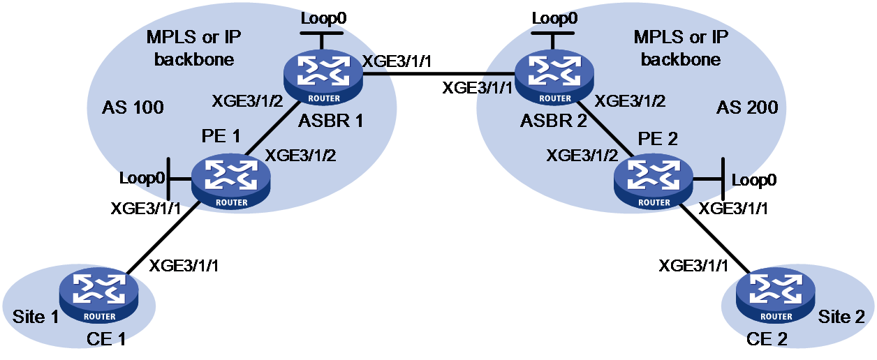
|
Device |
Interface |
IP address |
Device |
Interface |
IP address |
|
CE 1 |
XGE3/1/1 |
100.1.1.1/24 |
ASBR 1 |
Loop0 |
192.2.2.2/32 |
|
PE 1 |
Loop0 |
192.1.1.1/32 |
|
XGE3/1/2 |
23.1.1.2/24 |
|
|
XGE3/1/2 |
23.1.1.1/24 |
|
XGE3/1/1 |
26.2.2.2/24 |
|
PE 2 |
Loop0 |
192.4.4.4/32 |
ASBR 2 |
Loop0 |
192.3.3.3/32 |
|
|
XGE3/1/2 |
22.2.2.1/24 |
|
XGE3/1/1 |
26.2.2.3/24 |
|
CE 2 |
XGE3/1/1 |
100.1.1.2/24 |
|
XGE3/1/2 |
22.2.2.3/24 |
Procedure
1. Configure CE 1.
<CE1> system-view
[CE1] interface ten-gigabitethernet 3/1/1
[CE1-Ten-GigabitEthernet3/1/1] ip address 100.1.1.1 24
[CE1-Ten-GigabitEthernet3/1/1] quit
2. Configure PE 1:
# Configure the LSR ID.
<PE1> system-view
[PE1] interface loopback 0
[PE1-LoopBack0] ip address 192.1.1.1 32
[PE1-LoopBack0] quit
[PE1] mpls lsr-id 192.1.1.1
# Enable L2VPN.
[PE1] l2vpn enable
# Enable global LDP.
[PE1] mpls ldp
[PE1-ldp] quit
# Enable LDP on Ten-GigabitEthernet 3/1/2, the interface connected to ASBR 1.
[PE1] interface ten-gigabitethernet 3/1/2
[PE1-Ten-GigabitEthernet3/1/2] ip address 23.1.1.1 24
[PE1-Ten-GigabitEthernet3/1/2] mpls enable
[PE1-Ten-GigabitEthernet3/1/2] mpls ldp enable
[PE1-Ten-GigabitEthernet3/1/2] quit
# Configure OSPF for LDP to create LSPs.
[PE1] ospf
[PE1-ospf-1] area 0
[PE1-ospf-1-area-0.0.0.0] network 23.1.1.0 0.0.0.255
[PE1-ospf-1-area-0.0.0.0] network 192.1.1.1 0.0.0.0
[PE1-ospf-1-area-0.0.0.0] quit
[PE1-ospf-1] quit
# Create a cross-connect group named vpna, create an EVPN instance for it, and enable MPLS encapsulation. Configure an RD and route targets for the EVPN instance.
[PE1] xconnect-group vpna
[PE1-xcg-vpna] evpn encapsulation mpls
[PE1-xcg-vpna-evpn-mpls] route-distinguisher 1:1
[PE1-xcg-vpna-evpn-mpls] vpn-target 1:1 export-extcommunity
[PE1-xcg-vpna-evpn-mpls] vpn-target 2:2 import-extcommunity
[PE1-xcg-vpna-evpn-mpls] quit
# Create cross-connect pw1 and map Ten-GigabitEthernet 3/1/1 to it. Create an EVPN PW on the cross-connect.
[PE1-xcg-vpna] connection pw1
[PE1-xcg-vpna-pw1] evpn local-service-id 2 remote-service-id 1
[PE1-xcg-vpna-pw1-2-1] quit
[PE1-xcg-vpna-pw1] ac interface ten-gigabitethernet 3/1/1
[PE1-xcg-vpna-pw1-Ten-GigabitEthernet3/1/1] quit
[PE1-xcg-vpna-pw1] quit
[PE1-xcg-vpna] quit
# Create an IBGP connection to ASBR 1, and enable BGP to advertise BGP EVPN routes and labeled unicast routes to ASBR 1.
[PE1] bgp 100
[PE1-bgp-default] peer 192.2.2.2 as-number 100
[PE1-bgp-default] peer 192.2.2.2 connect-interface LoopBack0
[PE1-bgp-default] address-family l2vpn evpn
[PE1-bgp-default-evpn] peer 192.2.2.2 enable
[PE1-bgp-default-evpn] peer 192.2.2.2 advertise encap-type mpls
[PE1-bgp-default] address-family ipv4 unicast
[PE1-bgp-default-ipv4] peer 192.2.2.2 enable
[PE1-bgp-default-ipv4] peer 192.2.2.2 label-route-capability
[PE1-bgp-default-ipv4] quit
[PE1-bgp-default] quit
# Configure BGP to advertise BGP EVPN routes to PE 2 to establish an EVPN PW.
[PE1] bgp 100
[PE1-bgp-default] peer 192.4.4.4 as-number 200
[PE1-bgp-default] peer 192.4.4.4 connect-interface LoopBack0
[PE1-bgp-default] peer 192.4.4.4 ebgp-max-hop 10
[PE1-bgp-default] address-family l2vpn evpn
[PE1-bgp-default-evpn] peer 192.4.4.4 enable
[PE1-bgp-default-evpn] peer 192.4.4.4 advertise encap-type mpls
[PE1-bgp-default-evpn] quit
[PE1-bgp-default] quit
3. Configure ASBR 1:
# Configure the LSR ID.
<ASBR1> system-view
[ASBR1] interface loopback 0
[ASBR1-LoopBack0] ip address 192.2.2.2 32
[ASBR1-LoopBack0] quit
[ASBR1] mpls lsr-id 192.2.2.2
# Enable L2VPN.
[ASBR1] l2vpn enable
# Enable global LDP.
[ASBR1] mpls ldp
[ASBR1-ldp] quit
# Enable LDP on Ten-GigabitEthernet 3/1/2, the interface connected to PE 1.
[ASBR1] interface ten-gigabitethernet 3/1/2
[ASBR1-Ten-GigabitEthernet3/1/2] ip address 23.1.1.2 24
[ASBR1-Ten-GigabitEthernet3/1/2] mpls enable
[ASBR1-Ten-GigabitEthernet3/1/2] mpls ldp enable
[ASBR1-Ten-GigabitEthernet3/1/2] quit
# Enable MPLS on Ten-GigabitEthernet 3/1/1, the interface connected to ASBR 2.
[ASBR1] interface ten-gigabitethernet 3/1/1
[ASBR1-Ten-GigabitEthernet3/1/1] ip address 26.2.2.2 24
[ASBR1-Ten-GigabitEthernet3/1/1] mpls enable
[ASBR1-Ten-GigabitEthernet3/1/1] quit
# Configure OSPF for LDP to create LSPs.
[ASBR1] ospf
[ASBR1-ospf-1] area 0
[ASBR1-ospf-1-area-0.0.0.0] network 23.1.1.0 0.0.0.255
[ASBR1-ospf-1-area-0.0.0.0] network 192.2.2.2 0.0.0.0
[ASBR1-ospf-1-area-0.0.0.0] quit
[ASBR1-ospf-1] quit
# Create routing policies.
[ASBR1] route-policy policy1 permit node 1
[ASBR1-route-policy-policy1-1] apply mpls-label
[ASBR1-route-policy-policy1-1] quit
[ASBR1] route-policy policy2 permit node 1
[ASBR1-route-policy-policy2-1] if-match mpls-label
[ASBR1-route-policy-policy2-1] apply mpls-label
[ASBR1-route-policy-policy2-1] quit
# Enable BGP on ASBR 1, and apply the routing policy policy2 to routes advertised to IBGP peer 192.1.1.1.
[ASBR1] bgp 100
[ASBR1-bgp-default] peer 192.1.1.1 as-number 100
[ASBR1-bgp-default] peer 192.1.1.1 connect-interface LoopBack0
[ASBR1-bgp-default] address-family ipv4 unicast
[ASBR1-bgp-default-ipv4] peer 192.1.1.1 enable
[ASBR1-bgp-default-ipv4] peer 192.1.1.1 route-policy policy2 export
# Enable the capability to advertise labeled routes to IBGP peer 192.1.1.1 and to receive labeled routes from the peer.
[ASBR1-bgp-default-ipv4] peer 192.1.1.1 label-route-capability
# Redistribute routes from OSPF process 1 to BGP.
[ASBR1-bgp-default-ipv4] import-route ospf 1
[ASBR1-bgp-default-ipv4] quit
# Advertise BGP EVPN routes to IBGP peer 192.1.1.1.
[ASBR1-bgp-default] address-family l2vpn evpn
[ASBR1-bgp-default-evpn] peer 192.1.1.1 enable
[ASBR1-bgp-default-evpn] peer 192.1.1.1 advertise encap-type mpls
[ASBR1-bgp-default-evpn] quit
# Apply routing policy policy1 to routes advertised to EBGP peer 26.2.2.3.
[ASBR1-bgp-default] peer 26.2.2.3 as-number 200
[ASBR1-bgp-default] address-family ipv4 unicast
[ASBR1-bgp-default-ipv4] peer 26.2.2.3 enable
[ASBR1-bgp-default-ipv4] peer 26.2.2.3 route-policy policy1 export
# Enable the capability to advertise labeled routes to EBGP peer 26.2.2.3 and to receive labeled routes from the peer.
[ASBR1-bgp-default-ipv4] peer 26.2.2.3 label-route-capability
[ASBR1-bgp-default-ipv4] quit
# Advertise BGP EVPN routes to EBGP peer 26.2.2.3.
[ASBR1-bgp-default] address-family l2vpn evpn
[ASBR1-bgp-default-evpn] peer 26.2.2.3 enable
[ASBR1-bgp-default-evpn] peer 26.2.2.3 advertise encap-type mpls
[ASBR1-bgp-default-evpn] quit
[ASBR1-bgp-default] quit
4. Configure ASBR 2:
# Configure the LSR ID.
<ASBR2> system-view
[ASBR2] interface loopback 0
[ASBR2-LoopBack0] ip address 192.3.3.3 32
[ASBR2-LoopBack0] quit
[ASBR2] mpls lsr-id 192.3.3.3
# Enable L2VPN.
[ASBR2] l2vpn enable
# Enable global LDP.
[ASBR2] mpls ldp
[ASBR2-ldp] quit
# Enable LDP on Ten-GigabitEthernet 3/1/2, the interface connected to PE 2.
[ASBR2] interface ten-gigabitethernet 3/1/2
[ASBR2-Ten-GigabitEthernet3/1/2] ip address 22.2.2.3 24
[ASBR2-Ten-GigabitEthernet3/1/2] mpls enable
[ASBR2-Ten-GigabitEthernet3/1/2] mpls ldp enable
[ASBR2-Ten-GigabitEthernet3/1/2] quit
# Enable MPLS on Ten-GigabitEthernet 3/1/1, the interface connected to ASBR 1.
[ASBR2] interface ten-gigabitethernet 3/1/1
[ASBR2-Ten-GigabitEthernet3/1/1] ip address 26.2.2.3 24
[ASBR2-Ten-GigabitEthernet3/1/1] mpls enable
[ASBR2-Ten-GigabitEthernet3/1/1] quit
# Configure OSPF for LDP to create LSPs.
[ASBR2] ospf
[ASBR2-ospf-1] area 0
[ASBR2-ospf-1-area-0.0.0.0] network 22.2.2.0 0.0.0.255
[ASBR2-ospf-1-area-0.0.0.0] network 192.3.3.3 0.0.0.0
[ASBR2-ospf-1-area-0.0.0.0] quit
[ASBR2-ospf-1] quit
# Create routing policies.
[ASBR2] route-policy policy1 permit node 1
[ASBR2-route-policy-policy1-1] apply mpls-label
[ASBR2-route-policy-policy1-1] quit
[ASBR2] route-policy policy2 permit node 1
[ASBR2-route-policy-policy2-1] if-match mpls-label
[ASBR2-route-policy-policy2-1] apply mpls-label
[ASBR2-route-policy-policy2-1] quit
# Enable BGP on ASBR 2, and apply the routing policy policy2 to routes advertised to IBGP peer 192.4.4.4.
[ASBR2] bgp 200
[ASBR2-bgp-default] peer 192.4.4.4 as-number 200
[ASBR2-bgp-default] peer 192.4.4.4 connect-interface LoopBack0
[ASBR2-bgp-default] address-family ipv4 unicast
[ASBR2-bgp-default-ipv4] peer 192.4.4.4 enable
[ASBR2-bgp-default-ipv4] peer 192.4.4.4 route-policy policy2 export
# Enable the capability to advertise labeled routes to IBGP peer 192.4.4.4 and to receive labeled routes from the peer.
[ASBR2-bgp-default-ipv4] peer 192.4.4.4 label-route-capability
# Redistribute routes from OSPF process 1 to BGP.
[ASBR2-bgp-default-ipv4] import-route ospf 1
[ASBR2-bgp-default-ipv4] quit
# Advertise BGP EVPN routes to IBGP peer 192.4.4.4.
[ASBR2-bgp-default] address-family l2vpn evpn
[ASBR2-bgp-default-evpn] peer 192.4.4.4 enable
[ASBR2-bgp-default-evpn] peer 192.4.4.4 advertise encap-type mpls
[ASBR2-bgp-default-evpn] quit
# Apply routing policy policy1 to routes advertised to EBGP peer 26.2.2.2.
[ASBR2-bgp-default] peer 26.2.2.2 as-number 100
[ASBR2-bgp-default] address-family ipv4 unicast
[ASBR2-bgp-default-ipv4] peer 26.2.2.2 enable
[ASBR2-bgp-default-ipv4] peer 26.2.2.2 route-policy policy1 export
# Enable the capability to advertise labeled routes to EBGP peer 26.2.2.2 and to receive labeled routes from the peer.
[ASBR2-bgp-default-ipv4] peer 26.2.2.2 label-route-capability
[ASBR2-bgp-default-ipv4] quit
# Advertise BGP EVPN routes to EBGP peer 26.2.2.2.
[ASBR2-bgp-default] address-family l2vpn evpn
[ASBR2-bgp-default-evpn] peer 26.2.2.2 enable
[ASBR2-bgp-default-evpn] peer 26.2.2.2 advertise encap-type mpls
[ASBR2-bgp-default-evpn] quit
[ASBR2-bgp-default] quit
5. Configure PE 2:
# Configure the LSR ID.
<PE2> system-view
[PE2] interface loopback 0
[PE2-LoopBack0] ip address 192.4.4.4 32
[PE2-LoopBack0] quit
[PE2] mpls lsr-id 192.4.4.4
# Enable L2VPN.
[PE2] l2vpn enable
# Enable global LDP.
[PE2] mpls ldp
[PE2-ldp] quit
# Enable LDP on Ten-GigabitEthernet 3/1/2, the interface connected to ASBR 2.
[PE2] interface ten-gigabitethernet 3/1/2
[PE2-Ten-GigabitEthernet3/1/2] ip address 22.2.2.1 24
[PE2-Ten-GigabitEthernet3/1/2] mpls enable
[PE2-Ten-GigabitEthernet3/1/2] mpls ldp enable
[PE2-Ten-GigabitEthernet3/1/2] quit
# Configure OSPF for LDP to create LSPs.
[PE2] ospf
[PE2-ospf-1] area 0
[PE2-ospf-1-area-0.0.0.0] network 192.4.4.4 0.0.0.0
[PE2-ospf-1-area-0.0.0.0] network 22.2.2.0 0.0.0.255
[PE2-ospf-1-area-0.0.0.0] quit
[PE2-ospf-1] quit
# Create a cross-connect group named vpna, create an EVPN instance for it, and enable MPLS encapsulation. Configure an RD and route targets for the EVPN instance.
[PE2] xconnect-group vpna
[PE2-xcg-vpna] evpn encapsulation mpls
[PE2-xcg-vpna-evpn-mpls] route-distinguisher 1:1
[PE2-xcg-vpna-evpn-mpls] vpn-target 2:2 export-extcommunity
[PE2-xcg-vpna-evpn-mpls] vpn-target 1:1 import-extcommunity
[PE2-xcg-vpna-evpn-mpls] quit
# Create cross-connect pw1 and map Ten-GigabitEthernet 3/1/1 to it. Create an EVPN PW on the cross-connect.
[PE2-xcg-vpna] connection pw1
[PE2-xcg-vpna-pw1] evpn local-service-id 1 remote-service-id 2
[PE2-xcg-vpna-pw1-1-2] quit
[PE2-xcg-vpna-pw1] ac interface ten-gigabitethernet 3/1/1
[PE2-xcg-vpna-pw1-Ten-GigabitEthernet3/1/1] quit
[PE2-xcg-vpna-pw1] quit
[PE2-xcg-vpna] quit
# Create an IBGP connection to ASBR 2, and enable BGP to advertise BGP EVPN routes and labeled unicast routes to ASBR 2.
[PE2] bgp 200
[PE2-bgp-default] peer 192.3.3.3 as-number 200
[PE2-bgp-default] peer 192.3.3.3 connect-interface LoopBack0
[PE2-bgp-default] address-family l2vpn evpn
[PE2-bgp-default-evpn] peer 192.3.3.3 enable
[PE2-bgp-default-evpn] peer 192.3.3.3 advertise encap-type mpls
[PE2-bgp-default-evpn] quit
[PE2-bgp-default] address-family ipv4 unicast
[PE2-bgp-default-ipv4] peer 192.3.3.3 enable
[PE2-bgp-default-ipv4] peer 192.3.3.3 label-route-capability
[PE2-bgp-default-ipv4] quit
[PE2-bgp-default] quit
# Configure BGP to advertise BGP EVPN routes to PE 1 to establish an EVPN PW.
[PE2] bgp 200
[PE2-bgp-default] peer 192.1.1.1 as-number 100
[PE2-bgp-default] peer 192.1.1.1 connect-interface LoopBack0
[PE2-bgp-default] peer 192.1.1.1 ebgp-max-hop 10
[PE2-bgp-default] address-family l2vpn evpn
[PE2-bgp-default-evpn] peer 192.1.1.1 enable
[PE2-bgp-default-evpn] peer 192.1.1.1 advertise encap-type mpls
[PE2-bgp-default-evpn] quit
[PE2-bgp-default] quit
6. Configure CE 2.
<CE2> system-view
[CE2] interface ten-gigabitethernet 3/1/1
[CE2-Ten-GigabitEthernet3/1/1] ip address 100.1.1.2 24
[CE2-Ten-GigabitEthernet3/1/1] quit
Verifying the configuration
# Verify that an EVPN PW has been established on PE 1.
[PE1] display l2vpn pw
Flags: M - main, B - backup, E - ecmp, BY - bypass, H - hub link, S - spoke link
N - no split horizon, A - administration, ABY - ac-bypass,
PBY - pw-bypass
Total number of PWs: 1
1 up, 0 blocked, 0 down, 0 defect, 0 idle, 0 duplicate
Xconnect-group Name: vpna
Peer PWID/RmtSite/SrvID In/Out Label Proto Flag Link ID State
192.4.4.4 1 710127/710126 EVPN M 0 Up
# Verify that an EVPN PW has been established on PE 2.
[PE2] display l2vpn pw
Flags: M - main, B - backup, E - ecmp, BY - bypass, H - hub link, S - spoke link
N - no split horizon, A - administration, ABY - ac-bypass
PBY - pw-bypass
Total number of PWs: 1
1 up, 0 blocked, 0 down, 0 defect, 0 idle, 0 duplicate
Xconnect-group Name: vpna
Peer PWID/RmtSite/SrvID In/Out Label Proto Flag Link ID State
192.1.1.1 2 710126/710127 EVPN M 0 Up
# Verify that CE 1 and CE 2 can ping each other. (Details not shown.)
Example: Configuring FRR for EVPN VPWS
Network configuration
As shown in Figure 23:
· Assign the links that connect CE 1 to PE 1 and PE 2 to a smart trunk.
· Configure EVPN VPWS on PE 1, PE 2, and PE 3.
· Establish a bypass PW between PE 1 and PE 2, and configure LDP to set up a public tunnel for the bypass PW.
· Establish a primary PW and a backup PW between PE 1 and PE 3, and establish a primary PW and a backup PW between PE 2 and PE 3,
· Configure RR 1 and RR 2 to modify the next hop attribute of routes and reassign MPLS labels to them when they reflect routes for PE 1 and PE 2.
· Configure RR 1 and RR 2 to modify route attributes by using routing policies for route selection.
· Assign PE 1, PE 2, and PE 3 to AS 100, and configure the AS to use OSPF as the IGP.
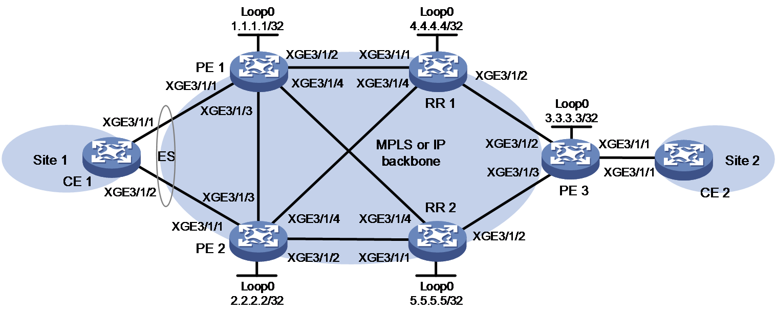
Table 1 Interface and IP address assignment
|
Device |
Interface |
IP address |
Device |
Interface |
IP address |
|
PE 1 |
Loop0 |
1.1.1.1/32 |
PE 3 |
Loop0 |
3.3.3.3/32 |
|
|
XGE3/1/1 |
- |
|
XGE3/1/1 |
- |
|
|
XGE3/1/2 |
10.1.1.1/24 |
|
XGE3/1/2 |
10.1.6.3/24 |
|
|
XGE3/1/3 |
10.1.2.1/24 |
|
XGE3/1/3 |
10.1.7.3/24 |
|
|
XGE3/1/4 |
10.1.3.1/24 |
RR 1 |
Loop0 |
4.4.4.4/32 |
|
PE 2 |
Loop0 |
2.2.2.2/32 |
|
XGE3/1/1 |
10.1.1.4/24 |
|
|
XGE3/1/1 |
- |
|
XGE3/1/2 |
10.1.6.4/24 |
|
|
XGE3/1/2 |
10.1.4.2/24 |
|
XGE3/1/4 |
10.1.5.4/24 |
|
|
XGE3/1/3 |
10.1.2.2/24 |
RR 2 |
Loop0 |
5.5.5.5/32 |
|
|
XGE3/1/4 |
10.1.5.2/24 |
|
XGE3/1/1 |
10.1.4.5/24 |
|
CE 1 |
RAGG1 |
100.1.1.1/24 |
|
XGE3/1/2 |
10.1.7.5/24 |
|
CE 2 |
XGE3/1/1 |
100.1.1.2/24 |
|
XGE3/1/4 |
10.1.3.5/24 |
Procedure
1. Configure CE 1:
# Create dynamic Layer 3 aggregate interface Route-Aggregation 1 and assign it an IP address.
<CE1> system-view
[CE1] interface route-aggregation 1
[CE1-Route-Aggregation1] link-aggregation mode dynamic
[CE1-Route-Aggregation1] ip address 100.1.1.1 24
[CE1-Route-Aggregation1] quit
# Assign Ten-GigabitEthernet 3/1/1 and Ten-GigabitEthernet 3/1/2 to aggregation group 1.
[CE1] interface ten-gigabitethernet 3/1/1
[CE1-Ten-GigabitEthernet3/1/1] port link-aggregation group 1
[CE1-Ten-GigabitEthernet3/1/1] quit
[CE1] interface ten-gigabitethernet 3/1/2
[CE1-Ten-GigabitEthernet3/1/2] port link-aggregation group 1
[CE1-Ten-GigabitEthernet3/1/2] quit
2. Configure PE 1:
# Configure an LSR ID.
<PE1> system-view
[PE1] interface loopback 0
[PE1-LoopBack0] ip address 1.1.1.1 32
[PE1-LoopBack0] quit
[PE1] mpls lsr-id 1.1.1.1
# Enable L2VPN.
[PE1] l2vpn enable
# Enable global LDP.
[PE1] mpls ldp
[PE1-ldp] quit
# Enable local FRR for EVPN VPWS globally.
[PE1] evpn multihoming vpws-frr local
# Configure Ten-GigabitEthernet 3/1/2 (the interface connected to RR 1), and enable MPLS and LDP on the interface.
[PE1] interface ten-gigabitethernet 3/1/2
[PE1-Ten-GigabitEthernet3/1/2] ip address 10.1.1.1 24
[PE1-Ten-GigabitEthernet3/1/2] mpls enable
[PE1-Ten-GigabitEthernet3/1/2] mpls ldp enable
[PE1-Ten-GigabitEthernet3/1/2] quit
# Configure Ten-GigabitEthernet 3/1/3 (the interface connected to PE 2), and enable MPLS and LDP on the interface.
[PE1] interface ten-gigabitethernet 3/1/3
[PE1-Ten-GigabitEthernet3/1/3] ip address 10.1.2.1 24
[PE1-Ten-GigabitEthernet3/1/3] mpls enable
[PE1-Ten-GigabitEthernet3/1/3] mpls ldp enable
[PE1-Ten-GigabitEthernet3/1/3] quit
#Configure Ten-GigabitEthernet 3/1/4 (the interface connected to RR 2), and enable MPLS and LDP on the interface.
[PE1] interface ten-gigabitethernet 3/1/4
[PE1-Ten-GigabitEthernet3/1/4] ip address 10.1.3.1 24
[PE1-Ten-GigabitEthernet3/1/4] mpls enable
[PE1-Ten-GigabitEthernet3/1/4] mpls ldp enable
[PE1-Ten-GigabitEthernet3/1/4] quit
# Configure OSPF for LDP to create LSPs.
[PE1] ospf
[PE1-ospf-1] area 0
[PE1-ospf-1-area-0.0.0.0] network 10.1.1.0 0.0.0.255
[PE1-ospf-1-area-0.0.0.0] network 10.1.2.0 0.0.0.255
[PE1-ospf-1-area-0.0.0.0] network 10.1.3.0 0.0.0.255
[PE1-ospf-1-area-0.0.0.0] network 1.1.1.1 0.0.0.0
[PE1-ospf-1-area-0.0.0.0] quit
[PE1-ospf-1] quit
# Configure PE 1 to establish IBGP peer relationships with RR 1 and RR 2, and configure BGP to advertise BGP EVPN routes.
[PE1] bgp 100
[PE1-bgp-default] peer 4.4.4.4 as-number 100
[PE1-bgp-default] peer 4.4.4.4 connect-interface loopback 0
[PE1-bgp-default] peer 5.5.5.5 as-number 100
[PE1-bgp-default] peer 5.5.5.5 connect-interface loopback 0
[PE1-bgp-default] address-family l2vpn evpn
[PE1-bgp-default-evpn] peer 4.4.4.4 enable
[PE1-bgp-default-evpn] peer 5.5.5.5 enable
[PE1-bgp-default-evpn] peer 4.4.4.4 advertise encap-type mpls
[PE1-bgp-default-evpn] peer 5.5.5.5 advertise encap-type mpls
[PE1-bgp-default-evpn] quit
[PE1-bgp-default] quit
# Configure S-Trunk for CE 1 to be dual-homed to PE 1 and PE 2.
[PE1] lacp system-priority 10
[PE1] lacp system-mac 1-1-1
[PE1] lacp system-number 1
[PE1] s-trunk id 1
[PE1-s-trunk1] s-trunk ip destination 10.1.2.2 source 10.1.2.1
[PE1-s-trunk1] quit
[PE1] interface route-aggregation 1
[PE1-Route-Aggregation1] link-aggregation mode dynamic
[PE1-Route-Aggregation1] s-trunk 1
[PE1-Route-Aggregation1] s-trunk port-role primary
[PE1-Route-Aggregation1] quit
[PE1] interface ten-gigabitethernet 3/1/1
[PE1-Ten-GigabitEthernet3/1/1] port link-aggregation group 1
[PE1-Ten-GigabitEthernet3/1/1] quit
# Assign an ESI to Route-Aggregation 1 and set its redundancy mode to all-active.
[PE1] interface route-aggregation 1
[PE1-Route-Aggregation1] esi 1.1.1.1.1
[PE1-Route-Aggregation1] evpn redundancy-mode all-active
[PE1-Route-Aggregation1] quit
# Create a cross-connect group named vpna, create an EVPN instance for it, and enable MPLS encapsulation. Configure an RD and route targets for the EVPN instance.
[PE1] xconnect-group vpna
[PE1-xcg-vpna] evpn encapsulation mpls
[PE1-xcg-vpna-evpn-mpls] route-distinguisher 1:1
[PE1-xcg-vpna-evpn-mpls] vpn-target 1:1 export-extcommunity
[PE1-xcg-vpna-evpn-mpls] vpn-target 1:1 import-extcommunity
[PE1-xcg-vpna-evpn-mpls] quit
# Create cross-connect pw1 and map Route-Aggregation 1 to it. Create an EVPN PW on the cross-connect.
[PE1] xconnect-group vpna
[PE1-xcg-vpna] connection pw1
[PE1-xcg-vpna-pw1] ac interface route-aggregation 1
[PE1-xcg-vpna-pw1-Route-Aggregation1] quit
[PE1-xcg-vpna-pw1] evpn local-service-id 1 remote-service-id 2
[PE1-xcg-vpna-pw1-1-2] quit
[PE1-xcg-vpna-pw1] quit
[PE1-xcg-vpna] quit
# Enable remote FRR for EVPN VPWS globally.
[PE1] evpn vpws-frr remote
3. Configure PE 2:
# Configure an LSR ID.
<PE2> system-view
[PE2] interface loopback 0
[PE2-LoopBack0] ip address 2.2.2.2 32
[PE2-LoopBack0] quit
[PE2] mpls lsr-id 2.2.2.2
# Enable L2VPN.
[PE2] l2vpn enable
# Enable global LDP.
[PE2] mpls ldp
[PE2-ldp] quit
# Enable local FRR for EVPN VPWS globally.
[PE2] evpn multihoming vpws-frr local
# Configure Ten-GigabitEthernet 3/1/2 (the interface connected to RR 2), and enable MPLS and LDP on the interface.
[PE2] interface ten-gigabitethernet 3/1/2
[PE2-Ten-GigabitEthernet3/1/2] ip address 10.1.4.2 24
[PE2-Ten-GigabitEthernet3/1/2] mpls enable
[PE2-Ten-GigabitEthernet3/1/2] mpls ldp enable
[PE2-Ten-GigabitEthernet3/1/2] quit
# Configure Ten-GigabitEthernet 3/1/3 (the interface connected to PE 1), and enable MPLS and LDP on the interface.
[PE2] interface ten-gigabitethernet 3/1/3
[PE2-Ten-GigabitEthernet3/1/3] ip address 10.1.2.2 24
[PE2-Ten-GigabitEthernet3/1/3] mpls enable
[PE2-Ten-GigabitEthernet3/1/3] mpls ldp enable
[PE2-Ten-GigabitEthernet3/1/3] quit
# Configure Ten-GigabitEthernet 3/1/4 (the interface connected to RR 1), and enable MPLS and LDP on the interface.
[PE2] interface ten-gigabitethernet 3/1/4
[PE2-Ten-GigabitEthernet3/1/4] ip address 10.1.5.2 24
[PE2-Ten-GigabitEthernet3/1/4] mpls enable
[PE2-Ten-GigabitEthernet3/1/4] mpls ldp enable
[PE2-Ten-GigabitEthernet3/1/4] quit
# Configure OSPF for LDP to create LSPs.
[PE2] ospf
[PE2-ospf-1] area 0
[PE2-ospf-1-area-0.0.0.0] network 10.1.2.0 0.0.0.255
[PE2-ospf-1-area-0.0.0.0] network 10.1.4.0 0.0.0.255
[PE2-ospf-1-area-0.0.0.0] network 10.1.5.0 0.0.0.255
[PE2-ospf-1-area-0.0.0.0] network 2.2.2.2 0.0.0.0
[PE2-ospf-1-area-0.0.0.0] quit
[PE2-ospf-1] quit
# Configure PE 2 to establish IBGP peer relationships with RR 1 and RR 2, and configure BGP to advertise BGP EVPN routes.
[PE2] bgp 100
[PE2-bgp-default] peer 4.4.4.4 as-number 100
[PE2-bgp-default] peer 4.4.4.4 connect-interface loopback 0
[PE2-bgp-default] peer 5.5.5.5 as-number 100
[PE2-bgp-default] peer 5.5.5.5 connect-interface loopback 0
[PE2-bgp-default] address-family l2vpn evpn
[PE2-bgp-default-evpn] peer 4.4.4.4 enable
[PE2-bgp-default-evpn] peer 5.5.5.5 enable
[PE2-bgp-default-evpn] peer 4.4.4.4 advertise encap-type mpls
[PE2-bgp-default-evpn] peer 5.5.5.5 advertise encap-type mpls
[PE2-bgp-default-evpn] quit
[PE2-bgp-default] quit
# Configure S-Trunk for CE 1 to be dual-homed to PE 1 and PE 2.
[PE2] lacp system-priority 10
[PE2] lacp system-mac 1-1-1
[PE2] lacp system-number 2
[PE2] s-trunk id 1
[PE2-s-trunk1] s-trunk ip destination 10.1.2.1 source 10.1.2.2
[PE2-s-trunk1] quit
[PE2] interface route-aggregation 1
[PE2-Route-Aggregation1] link-aggregation mode dynamic
[PE2-Route-Aggregation1] s-trunk 1
[PE2-Route-Aggregation1] s-trunk port-role primary
[PE2-Route-Aggregation1] quit
[PE2] interface ten-gigabitethernet 3/1/1
[PE2-Ten-GigabitEthernet3/1/1] port link-aggregation group 1
[PE2-Ten-GigabitEthernet3/1/1] quit
# Assign an ESI to Route-Aggregation 1 and set its redundancy mode to all-active.
[PE2] interface route-aggregation 1
[PE2-Route-Aggregation1] esi 1.1.1.1.1
[PE2-Route-Aggregation1] evpn redundancy-mode all-active
[PE2-Route-Aggregation1] quit
# Create a cross-connect group named vpna, create an EVPN instance for it, and enable MPLS encapsulation. Configure an RD and route targets for the EVPN instance.
[PE2] xconnect-group vpna
[PE2-xcg-vpna] evpn encapsulation mpls
[PE2-xcg-vpna-evpn-mpls] route-distinguisher 1:1
[PE2-xcg-vpna-evpn-mpls] vpn-target 1:1 export-extcommunity
[PE2-xcg-vpna-evpn-mpls] vpn-target 1:1 import-extcommunity
[PE2-xcg-vpna-evpn-mpls] quit
# Create cross-connect pw1 and map Route-Aggregation 1 to it. Create an EVPN PW on the cross-connect.
[PE2] xconnect-group vpna
[PE2-xcg-vpna] connection pw1
[PE2-xcg-vpna-pw1] ac interface route-aggregation 1
[PE2-xcg-vpna-pw1-Route-Aggregation1] quit
[PE2-xcg-vpna-pw1] evpn local-service-id 1 remote-service-id 2
[PE2-xcg-vpna-pw1-1-2] quit
[PE2-xcg-vpna-pw1] quit
[PE2-xcg-vpna] quit
# Enable remote FRR for EVPN VPWS globally.
[PE2] evpn vpws-frr remote
4. Configure RR 1:
# Configure an LSR ID.
<RR1> system-view
[RR1] interface loopback 0
[RR1-LoopBack0] ip address 4.4.4.4 32
[RR1-LoopBack0] quit
[RR1] mpls lsr-id 4.4.4.4
# Enable L2VPN.
[RR1] l2vpn enable
# Enable global LDP.
[RR1] mpls ldp
[RR1-ldp] quit
# Configure Ten-GigabitEthernet 3/1/1 (the interface connected to PE 1), and enable MPLS and LDP on the interface.
[RR1] interface ten-gigabitethernet 3/1/1
[RR1-Ten-GigabitEthernet3/1/1] ip address 10.1.1.4 24
[RR1-Ten-GigabitEthernet3/1/1] mpls enable
[RR1-Ten-GigabitEthernet3/1/1] mpls ldp enable
[RR1-Ten-GigabitEthernet3/1/1] quit
# Configure Ten-GigabitEthernet 3/1/4 (the interface connected to PE 2), and enable MPLS and LDP on the interface.
[RR1] interface ten-gigabitethernet 3/1/4
[RR1-Ten-GigabitEthernet3/1/4] ip address 10.1.5.4 24
[RR1-Ten-GigabitEthernet3/1/4] mpls enable
[RR1-Ten-GigabitEthernet3/1/4] mpls ldp enable
[RR1-Ten-GigabitEthernet3/1/4] quit
# Configure Ten-GigabitEthernet 3/1/2 (the interface connected to PE 3), and enable MPLS and LDP on the interface.
[RR1] interface ten-gigabitethernet 3/1/2
[RR1-Ten-GigabitEthernet3/1/2] ip address 10.1.6.4 24
[RR1-Ten-GigabitEthernet3/1/2] mpls enable
[RR1-Ten-GigabitEthernet3/1/2] mpls ldp enable
[RR1-Ten-GigabitEthernet3/1/2] quit
# Configure OSPF for LDP to create LSPs.
[RR1] ospf
[RR1-ospf-1] area 0
[RR1-ospf-1-area-0.0.0.0] network 10.1.1.0 0.0.0.255
[RR1-ospf-1-area-0.0.0.0] network 10.1.5.0 0.0.0.255
[RR1-ospf-1-area-0.0.0.0] network 10.1.6.0 0.0.0.255
[RR1-ospf-1-area-0.0.0.0] network 4.4.4.4 0.0.0.0
[RR1-ospf-1-area-0.0.0.0] quit
[RR1-ospf-1] quit
# Configure routing policies used for modifying the costs of routes.
[RR1] route-policy policy1 permit node 10
[RR1-route-policy-policy1-10] if-match route-type bgp-evpn-ad
[RR1-route-policy-policy1-10] apply cost 200
[RR1-route-policy-policy1-10] quit
[RR1] route-policy policy2 permit node 20
[RR1-route-policy-policy2-10] if-match route-type bgp-evpn-ad
[RR1-route-policy-policy2-10] apply cost 500
[RR1-route-policy-policy2-10] quit
# Configure RR 1 to establish IBGP peer relationships with PE 1, PE 2, and PE 3.
[RR1] bgp 100
[RR1-bgp-default] peer 1.1.1.1 as-number 100
[RR1-bgp-default] peer 2.2.2.2 as-number 100
[RR1-bgp-default] peer 3.3.3.3 as-number 100
[RR1-bgp-default] peer 1.1.1.1 connect-interface loopback 0
[RR1-bgp-default] peer 2.2.2.2 connect-interface loopback 0
[RR1-bgp-default] peer 3.3.3.3 connect-interface loopback 0
# Configure BGP to advertise BGP EVPN routes, and disable route target filtering for BGP EVPN routes.
[RR1-bgp-default] address-family l2vpn evpn
[RR1-bgp-default-evpn] peer 1.1.1.1 enable
[RR1-bgp-default-evpn] peer 2.2.2.2 enable
[RR1-bgp-default-evpn] peer 3.3.3.3 enable
[RR1-bgp-default-evpn] peer 1.1.1.1 advertise encap-type mpls
[RR1-bgp-default-evpn] peer 2.2.2.2 advertise encap-type mpls
[RR1-bgp-default-evpn] peer 3.3.3.3 advertise encap-type mpls
[RR1-bgp-default-evpn] undo policy vpn-target
# Configure RR 1 as an RR.
[RR1-bgp-default-evpn] peer 1.1.1.1 reflect-client
[RR1-bgp-default-evpn] peer 2.2.2.2 reflect-client
[RR1-bgp-default-evpn] peer 3.3.3.3 reflect-client
# Enable RR to change the attributes of routes to be reflected.
[RR1-bgp-default-evpn] reflect change-path-attribute
# Set the local router as the next hop for routes sent to PE 1 and PE 2.
[RR1-bgp-default-evpn] peer 1.1.1.1 next-hop-local
[RR1-bgp-default-evpn] peer 2.2.2.2 next-hop-local
# Add PE 1 and PE 2 to the nearby cluster.
[RR1-bgp-default-evpn] peer 1.1.1.1 reflect-nearby-group
[RR1-bgp-default-evpn] peer 2.2.2.2 reflect-nearby-group
# Apply routing policy policy1 to routes advertised to IBGP peer 1.1.1.1.
[RR1-bgp-default-evpn] peer 1.1.1.1 route-policy policy1 export
# Apply routing policy policy2 to routes advertised to IBGP peer 2.2.2.2.
[RR1-bgp-default-evpn] peer 2.2.2.2 route-policy policy2 export
[RR1-bgp-default-evpn] quit
[RR1-bgp-default] quit
5. Configure RR 2:
# Configure an LSR ID.
<RR2> system-view
[RR2] interface loopback 0
[RR2-LoopBack0] ip address 5.5.5.5 32
[RR2-LoopBack0] quit
[RR2] mpls lsr-id 5.5.5.5
# Enable L2VPN.
[RR2] l2vpn enable
# Enable global LDP.
[RR2] mpls ldp
[RR2-ldp] quit
# Configure Ten-GigabitEthernet 3/1/4 (the interface connected to PE 1), and enable MPLS and LDP on the interface.
[RR2] interface ten-gigabitethernet 3/1/4
[RR2-Ten-GigabitEthernet3/1/4] ip address 10.1.3.5 24
[RR2-Ten-GigabitEthernet3/1/4] mpls enable
[RR2-Ten-GigabitEthernet3/1/4] mpls ldp enable
[RR2-Ten-GigabitEthernet3/1/4] quit
# Configure Ten-GigabitEthernet 3/1/1 (the interface connected to PE 2), and enable MPLS and LDP on the interface.
[RR2] interface ten-gigabitethernet 3/1/1
[RR2-Ten-GigabitEthernet3/1/1] ip address 10.1.4.5 24
[RR2-Ten-GigabitEthernet3/1/1] mpls enable
[RR2-Ten-GigabitEthernet3/1/1] mpls ldp enable
[RR2-Ten-GigabitEthernet3/1/1] quit
# Configure Ten-GigabitEthernet 3/1/2 (the interface connected to PE 3), and enable MPLS and LDP on the interface.
[RR2] interface ten-gigabitethernet 3/1/2
[RR2-Ten-GigabitEthernet3/1/2] ip address 10.1.7.5 24
[RR2-Ten-GigabitEthernet3/1/2] mpls enable
[RR2-Ten-GigabitEthernet3/1/2] mpls ldp enable
[RR2-Ten-GigabitEthernet3/1/2] quit
# Configure OSPF for LDP to create LSPs.
[RR2] ospf
[RR2-ospf-1] area 0
[RR2-ospf-1-area-0.0.0.0] network 10.1.3.0 0.0.0.255
[RR2-ospf-1-area-0.0.0.0] network 10.1.4.0 0.0.0.255
[RR2-ospf-1-area-0.0.0.0] network 10.1.7.0 0.0.0.255
[RR2-ospf-1-area-0.0.0.0] network 5.5.5.5 0.0.0.0
[RR2-ospf-1-area-0.0.0.0] quit
[RR2-ospf-1] quit
# Configure routing policies used for modifying the costs of routes.
[RR2] route-policy policy1 permit node 10
[RR2-route-policy-policy1-10] if-match route-type bgp-evpn-ad
[RR2-route-policy-policy1-10] apply cost 200
[RR2-route-policy-policy1-10] quit
[RR2] route-policy policy2 permit node 20
[RR2-route-policy-policy2-10] if-match route-type bgp-evpn-ad
[RR2-route-policy-policy2-10] apply cost 500
[RR2-route-policy-policy2-10] quit
# Configure RR 2 to establish IBGP peer relationships with PE 1, PE 2, and PE 3.
[RR2] bgp 100
[RR2-bgp-default] peer 1.1.1.1 as-number 100
[RR2-bgp-default] peer 2.2.2.2 as-number 100
[RR2-bgp-default] peer 3.3.3.3 as-number 100
[RR2-bgp-default] peer 1.1.1.1 connect-interface loopback 0
[RR2-bgp-default] peer 2.2.2.2 connect-interface loopback 0
[RR2-bgp-default] peer 3.3.3.3 connect-interface loopback 0
# Configure BGP to advertise BGP EVPN routes, and disable route target filtering for BGP EVPN routes.
[RR2-bgp-default] address-family l2vpn evpn
[RR2-bgp-default-evpn] peer 1.1.1.1 enable
[RR2-bgp-default-evpn] peer 2.2.2.2 enable
[RR2-bgp-default-evpn] peer 3.3.3.3 enable
[RR2-bgp-default-evpn] peer 1.1.1.1 advertise encap-type mpls
[RR2-bgp-default-evpn] peer 2.2.2.2 advertise encap-type mpls
[RR2-bgp-default-evpn] peer 3.3.3.3 advertise encap-type mpls
[RR2-bgp-default-evpn] undo policy vpn-target
# Configure RR 2 as an RR.
[RR2-bgp-default-evpn] peer 1.1.1.1 reflect-client
[RR2-bgp-default-evpn] peer 2.2.2.2 reflect-client
[RR2-bgp-default-evpn] peer 3.3.3.3 reflect-client
# Enable the RR to change the attributes of routes to be reflected.
[RR2-bgp-default-evpn] reflect change-path-attribute
# Set the local router as the next hop for routes sent to PE 1 and PE 2.
[RR2-bgp-default-evpn] peer 1.1.1.1 next-hop-local
[RR2-bgp-default-evpn] peer 2.2.2.2 next-hop-local
# Add PE 1 and PE 2 to the nearby cluster.
[RR2-bgp-default-evpn] peer 1.1.1.1 reflect-nearby-group
[RR2-bgp-default-evpn] peer 2.2.2.2 reflect-nearby-group
# Apply routing policy policy1 to routes advertised to IBGP peer 1.1.1.1.
[RR2-bgp-default-evpn] peer 1.1.1.1 route-policy policy1 export
# Apply routing policy policy2 to routes advertised to IBGP peer 2.2.2.2.
[RR2-bgp-default-evpn] peer 2.2.2.2 route-policy policy2 export
[RR2-bgp-default-evpn] quit
[RR2-bgp-default] quit
6. Configure PE 3:
# Configure an LSR ID.
<PE3> system-view
[PE3] interface loopback 0
[PE3-LoopBack0] ip address 3.3.3.3 32
[PE3-LoopBack0] quit
[PE3] mpls lsr-id 3.3.3.3
# Enable L2VPN.
[PE3] l2vpn enable
# Enable global LDP.
[PE3] mpls ldp
[PE3-ldp] quit
# Enable local FRR for EVPN VPWS globally.
[PE3] evpn multihoming vpws-frr local
# Configure Ten-GigabitEthernet 3/1/2 (the interface connected to RR 1), and enable MPLS and LDP on the interface.
[PE3] interface ten-gigabitethernet 3/1/2
[PE3-Ten-GigabitEthernet3/1/2] ip address 10.1.6.3 24
[PE3-Ten-GigabitEthernet3/1/2] mpls enable
[PE3-Ten-GigabitEthernet3/1/2] mpls ldp enable
[PE3-Ten-GigabitEthernet3/1/2] quit
# Configure Ten-GigabitEthernet 3/1/3 (the interface connected to RR 2), and enable MPLS and LDP on the interface.
[PE3] interface ten-gigabitethernet 3/1/3
[PE3-Ten-GigabitEthernet3/1/3] ip address 10.1.7.3 24
[PE3-Ten-GigabitEthernet3/1/3] mpls enable
[PE3-Ten-GigabitEthernet3/1/3] mpls ldp enable
[PE3-Ten-GigabitEthernet3/1/3] quit
# Configure OSPF for LDP to create LSPs.
[PE3] ospf
[PE3-ospf-1] area 0
[PE3-ospf-1-area-0.0.0.0] network 10.1.6.0 0.0.0.255
[PE3-ospf-1-area-0.0.0.0] network 10.1.7.0 0.0.0.255
[PE3-ospf-1-area-0.0.0.0] network 3.3.3.3 0.0.0.0
[PE3-ospf-1-area-0.0.0.0] quit
[PE3-ospf-1] quit
# Configure PE 3 to establish IBGP peer relationships with RR 1 and RR 2, and configure BGP to advertise EVPN routes.
[PE3] bgp 100
[PE3-bgp-default] peer 4.4.4.4 as-number 100
[PE3-bgp-default] peer 4.4.4.4 connect-interface loopback 0
[PE3-bgp-default] peer 5.5.5.5 as-number 100
[PE3-bgp-default] peer 5.5.5.5 connect-interface loopback 0
[PE3-bgp-default] address-family l2vpn evpn
[PE3-bgp-default-evpn] peer 4.4.4.4 enable
[PE3-bgp-default-evpn] peer 5.5.5.5 enable
[PE3-bgp-default-evpn] peer 4.4.4.4 advertise encap-type mpls
[PE3-bgp-default-evpn] peer 5.5.5.5 advertise encap-type mpls
[PE3-bgp-default-evpn] quit
[PE3-bgp-default] quit
# Create a cross-connect group named vpna, create an EVPN instance for it, and enable MPLS encapsulation. Configure an RD and route targets for the EVPN instance.
[PE3] xconnect-group vpna
[PE3-xcg-vpna] evpn encapsulation mpls
[PE3-xcg-vpna-evpn-mpls] route-distinguisher 1:1
[PE3-xcg-vpna-evpn-mpls] vpn-target 1:1 export-extcommunity
[PE3-xcg-vpna-evpn-mpls] vpn-target 1:1 import-extcommunity
[PE3-xcg-vpna-evpn-mpls] quit
# Create cross-connect pw1 and map Ten-GigabitEthernet 3/1/1 to it. Create an EVPN PW on the cross-connect.
[PE3] xconnect-group vpna
[PE3-xcg-vpna] connection pw1
[PE3-xcg-vpna-pw1] ac interface ten-gigabitethernet 3/1/1
[PE3-xcg-vpna-pw1-Ten-GigabitEthernet3/1/1] quit
[PE3-xcg-vpna-pw1] evpn local-service-id 2 remote-service-id 1
[PE3-xcg-vpna-pw1-2-1] quit
[PE3-xcg-vpna-pw1] quit
[PE3-xcg-vpna] quit
7. Configure CE 2.
<CE2> system-view
[CE2] interface ten-gigabitethernet 3/1/1
[CE2-Vlan-interface10] ip address 100.1.1.2 24
[CE2-Vlan-interface10] quit
Verifying the configuration
1. Verify PW information.
# Verify that PE 1 has established a primary PW and a backup PW with PE 3 and has established a bypass PW with PE 2.
<PE1> display l2vpn pw
Flags: M - main, B - backup, E - ecmp, BY - bypass, H - hub link, S - spoke link
N - no split horizon, A - administration, ABY - ac-bypass
PBY - pw-bypass
Total number of PWs: 3
1 up, 2 blocked, 0 down, 0 defect, 0 idle, 0 duplicate
Xconnect-group Name: vpna
Peer PWID/RmtSite/SrvID In/Out Label Proto Flag Link ID State
4.4.4.4 2 1151/1403 EVPN M 0 Up
5.5.5.5 2 1151/1275 EVPN B 0 Blocked
2.2.2.2 1 1151/1151 EVPN ABY 1 Blocked
# Verify that PE 2 has established a primary PW and a backup PW with PE 3 and has established a bypass PW with PE 1.
<PE2> display l2vpn pw
Flags: M - main, B - backup, E - ecmp, BY - bypass, H - hub link, S - spoke link
N - no split horizon, A - administration, ABY - ac-bypass
PBY - pw-bypass
Total number of PWs: 3
1 up, 2 blocked, 0 down, 0 defect, 0 idle, 0 duplicate
Xconnect-group Name: vpna
Peer PWID/RmtSite/SrvID In/Out Label Proto Flag Link ID State
5.5.5.5 2 1152/1404 EVPN M 0 Up
4.4.4.4 2 1152/1276 EVPN B 0 Blocked
1.1.1.1 1 1152/1152 EVPN ABY 1 Blocked
2. Verify that CE 1 and CE 2 can ping each other.
Example: Configuring LDP PWs as ACs for EVPN PWs
Network configuration
As shown in Figure 24:
· PE 1 and PE 2 are border devices on both the VPWS network and EVPN VPWS network. PE 4 belongs to the VPWS network. PE 3 belongs to the EVPN VPWS network.
· PE 1, PE 2, and PE 4 use LDP to establish LDP PWs.
· PE 4 is dual-homed to PE 1 and PE 2 through two LDP PWs.
· On PE 1 and PE 2, configure LDP PWs as UPWs (ACs) for EVPN PWs for the VPWS and EVPN VPWS networks to communicate with each other.
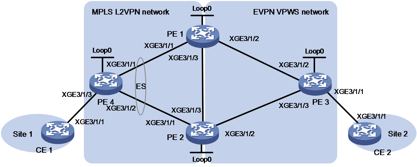
|
Device |
Interface |
IP address |
Device |
Interface |
IP address |
|
PE 1 |
Loop0 |
1.1.1.9/32 |
PE 3 |
Loop0 |
3.3.3.9/32 |
|
|
XGE3/1/1 |
10.1.1.1/24 |
|
XGE3/1/1 |
- |
|
|
XGE3/1/2 |
30.1.1.1/24 |
|
XGE3/1/2 |
30.1.1.3/24 |
|
|
XGE3/1/3 |
10.1.3.1/24 |
|
XGE3/1/3 |
10.1.2.3/24 |
|
PE 2 |
Loop0 |
2.2.2.9/32 |
PE 4 |
Loop0 |
4.4.4.9/32 |
|
|
XGE3/1/1 |
20.1.1.2/24 |
|
XGE3/1/3 |
- |
|
|
XGE3/1/2 |
10.1.2.2/24 |
|
XGE3/1/1 |
10.1.1.4/24 |
|
|
XGE3/1/3 |
10.1.3.2/24 |
|
XGE3/1/2 |
20.1.1.4/24 |
|
CE 1 |
XGE3/1/1 |
100.1.1.1/32 |
CE 2 |
XGE3/1/1 |
100.1.1.2/32 |
Procedure
1. Configure CE 1.
<CE1> system-view
[CE1] interface ten-gigabitethernet 3/1/1
[CE1-Ten-GigabitEthernet3/1/1] ip address 100.1.1.1 24
[CE1-Ten-GigabitEthernet3/1/1] quit
2. Configure PE 4:
# Configure the LSR ID.
<PE4> system-view
[PE4] interface loopback 0
[PE4-LoopBack0] ip address 1.1.1.9 32
[PE4-LoopBack0] quit
[PE4] mpls lsr-id 1.1.1.9
# Enable global LDP.
[PE4] mpls ldp
[PE4-ldp] quit
# Enable L2VPN.
[PE4] l2vpn enable
# Configure Ten-GigabitEthernet 3/1/1 (the interface connected to PE 1), and enable LDP on the interface.
[PE4] interface ten-gigabitethernet 3/1/1
[PE4-Ten-GigabitEthernet3/1/1] ip address 10.1.1.4 24
[PE4-Ten-GigabitEthernet3/1/1] ospf 1 area 0
[PE4-Ten-GigabitEthernet3/1/1] mpls enable
[PE4-Ten-GigabitEthernet3/1/1] mpls ldp enable
[PE4-Ten-GigabitEthernet3/1/1] undo shutdown
[PE4-Ten-GigabitEthernet3/1/1] quit
# Configure Ten-GigabitEthernet 3/1/2 (the interface connected to PE 2), and enable LDP on the interface.
[PE4] interface ten-gigabitethernet 3/1/2
[PE4-Ten-GigabitEthernet3/1/2] ip address 20.1.1.4 24
[PE4-Ten-GigabitEthernet3/1/2] ospf 1 area 0
[PE4-Ten-GigabitEthernet3/1/2] mpls enable
[PE4-Ten-GigabitEthernet3/1/2] mpls ldp enable
[PE4-Ten-GigabitEthernet3/1/2] undo shutdown
[PE4-Ten-GigabitEthernet3/1/2] quit
# Create cross-connect pw1 in cross-connect group vpna and map Ten-GigabitEthernet 3/1/3 to the cross-connect. Create an LDP PW on the cross-connect. Configure a backup PW for the LDP PW, and enable the dual receive feature for PW redundancy.
[PE4] xconnect-group vpna
[PE4-xcg-vpna] connection pw1
[PE4-xcg-vpna-pw1] ac interface ten-gigabitethernet 3/1/3
[PE4-xcg-vpna-pw1-Ten-GigabitEthernet3/1/3] quit
[PE4-xcg-vpna-pw1] protection dual-receive
[PE4-xcg-vpna-pw1] peer 1.1.1.9 pw-id 500
[PE4-xcg-vpna-pw1-1.1.1.9-500] backup-peer 2.2.2.9 pw-id 500
[PE4-xcg-vpna-pw1-1.1.1.9-500-backup] quit
[PE4-xcg-vpna-pw1-1.1.1.9-500] quit
[PE4-xcg-vpna-pw1] quit
[PE4-xcg-vpna] quit
3. Configure PE 1:
# Assign an IP address to Loopback 0.
<PE1> system-view
[PE1] interface loopback 0
[PE1-LoopBack1] ip address 1.1.1.9 32
[PE1-LoopBack1] quit
# Configure the LSR ID.
[PE1] mpls lsr-id 1.1.1.9
# Enable global LDP.
[PE1] mpls ldp
[PE1-ldp] quit
# Enable L2VPN.
[PE1] l2vpn enable
# Configure OSPF for LDP to create LSPs.
[PE1] ospf
[PE1-ospf-1] area 0
[PE1-ospf-1-area-0.0.0.0] network 10.1.1.0 0.0.0.255
[PE1-ospf-1-area-0.0.0.0] network 30.1.1.0 0.0.0.255
[PE1-ospf-1-area-0.0.0.0] network 10.1.3.0 0.0.0.255
[PE1-ospf-1-area-0.0.0.0] network 1.1.1.9 0.0.0.0
[PE1-ospf-1] quit
# Configure Ten-GigabitEthernet 3/1/2 (the interface connected to PE 4), and enable LDP on the interface.
[PE1] interface ten-gigabitethernet 3/1/2
[PE1-Ten-GigabitEthernet3/1/2] ip address 10.1.1.1 24
[PE1-Ten-GigabitEthernet3/1/2] mpls enable
[PE1-Ten-GigabitEthernet3/1/2] mpls ldp enable
[PE1-Ten-GigabitEthernet3/1/2] undo shutdown
[PE1-Ten-GigabitEthernet3/1/2] quit
# Configure Ten-GigabitEthernet 3/1/2 (the interface connected to PE 3), and enable LDP on the interface.
[PE1] interface ten-gigabitethernet 3/1/2
[PE1-Ten-GigabitEthernet3/1/2] ip address 30.1.1.1 24
[PE1-Ten-GigabitEthernet3/1/2] mpls enable
[PE1-Ten-GigabitEthernet3/1/2] mpls ldp enable
[PE1-Ten-GigabitEthernet3/1/2] undo shutdown
[PE1-Ten-GigabitEthernet3/1/2] quit
# Configure Ten-GigabitEthernet 3/1/3 (the interface connected to PE 2), and enable LDP on the interface.
[PE1] interface ten-gigabitethernet 3/1/3
[PE1-Ten-GigabitEthernet3/1/3] ip address 10.1.3.1 24
[PE1-Ten-GigabitEthernet3/1/3] mpls enable
[PE1-Ten-GigabitEthernet3/1/3] mpls ldp enable
[PE1-Ten-GigabitEthernet3/1/3] undo shutdown
[PE1-Ten-GigabitEthernet3/1/3] quit
# Create IBGP connections to PE 2 and PE 3, and enable BGP to advertise BGP EVPN routes to PE 2 and PE 3.
[PE1] bgp 100
[PE1-bgp-default] peer 2.2.2.9 as-number 100
[PE1-bgp-default] peer 2.2.2.9 connect-interface loopback 0
[PE1-bgp-default] peer 3.3.3.9 as-number 100
[PE1-bgp-default] peer 3.3.3.9 connect-interface loopback 0
[PE1-bgp-default] address-family l2vpn evpn
[PE1-bgp-default-evpn] peer 2.2.2.9 enable
[PE1-bgp-default-evpn] peer 3.3.3.9 enable
[PE1-bgp-default-evpn] peer 2.2.2.9 advertise encap-type mpls
[PE1-bgp-default-evpn] peer 3.3.3.9 advertise encap-type mpls
[PE1-bgp-default-evpn] quit
[PE1-bgp-default] quit
# Create a PW class and set its data encapsulation type to Ethernet.
[PE1] pw-class aaa
[PE1-pw-class-aaa] pw-type ethernet
[PE1-pw-class-aaa] quit
# Create a cross-connect group named vpna, create an EVPN instance for it, and enable MPLS encapsulation. Configure an RD and route targets for the EVPN instance.
[PE1] xconnect-group vpna
[PE1-xcg-vpna] evpn encapsulation mpls
[PE1-xcg-vpna-evpn-mpls] route-distinguisher 1:1
[PE1-xcg-vpna-evpn-mpls] vpn-target 1:1 export-extcommunity
[PE1-xcg-vpna-evpn-mpls] vpn-target 1:1 import-extcommunity
[PE1-xcg-vpna-evpn-mpls] quit
# Create cross-connect pw1 and set up a UPW between PE 4 and PE 1. Assign an ESI to the UPW and set its redundancy mode to all-active. Create an EVPN PW on the cross-connect.
[PE1-xcg-vpna] connection pw1
[PE1-xcg-vpna-pw1] peer 4.4.4.9 pw-id 500 pw-class aaa
[PE1-xcg-vpna-pw1-4.4.4.9-500] esi 1.1.1.1.1
[PE1-xcg-vpna-pw1-4.4.4.9-500] evpn redundancy-mode all-active
[PE1-xcg-vpna-pw1-4.4.4.9-500] quit
[PE1-xcg-vpna-pw1] evpn local-service-id 1 remote-service-id 2
[PE1-xcg-vpna-pw1-1-2] quit
[PE1-xcg-vpna-pw1] quit
[PE1-xcg-vpna] quit
4. Configure PE 2:
# Configure the LSR ID.
<PE2> system-view
[PE2] interface loopback 0
[PE2-LoopBack0] ip address 2.2.2.9 32
[PE2-LoopBack0] quit
[PE2] mpls lsr-id 2.2.2.9
# Enable global LDP.
[PE2] mpls ldp
[PE2-ldp] quit
# Enable L2VPN.
[PE2] l2vpn enable
# Configure OSPF for LDP to create LSPs.
[PE2] ospf
[PE2-ospf-1] area 0
[PE2-ospf-1-area-0.0.0.0] network 10.1.2.0 0.0.0.255
[PE2-ospf-1-area-0.0.0.0] network 20.1.1.0 0.0.0.255
[PE2-ospf-1-area-0.0.0.0] network 10.1.3.0 0.0.0.255
[PE2-ospf-1-area-0.0.0.0] network 2.2.2.9 0.0.0.0
[PE2-ospf-1] quit
# Configure Ten-GigabitEthernet 3/1/3 (the interface connected to PE 1), and enable LDP on the interface.
[PE2] interface ten-gigabitethernet 3/1/3
[PE2-Ten-GigabitEthernet3/1/3] ip address 10.1.3.2 24
[PE2-Ten-GigabitEthernet3/1/3] mpls enable
[PE2-Ten-GigabitEthernet3/1/3] mpls ldp enable
[PE2-Ten-GigabitEthernet3/1/3] undo shutdown
[PE2-Ten-GigabitEthernet3/1/3] quit
# Configure Ten-GigabitEthernet 3/1/2 (the interface connected to PE 3), and enable LDP on the interface.
[PE2] interface ten-gigabitethernet 3/1/2
[PE2-Ten-GigabitEthernet3/1/2] ip address 10.1.2.1 24
[PE2-Ten-GigabitEthernet3/1/2] mpls enable
[PE2-Ten-GigabitEthernet3/1/2] mpls ldp enable
[PE2-Ten-GigabitEthernet3/1/2] undo shutdown
[PE2-Ten-GigabitEthernet3/1/2] quit
# Configure Ten-GigabitEthernet 3/1/2 (the interface connected to PE 4), and enable LDP on the interface.
[PE2] interface ten-gigabitethernet 3/1/2
[PE2-Ten-GigabitEthernet3/1/2] ip address 20.1.1.2 24
[PE2-Ten-GigabitEthernet3/1/2] mpls enable
[PE2-Ten-GigabitEthernet3/1/2] mpls ldp enable
[PE2-Ten-GigabitEthernet3/1/2] undo shutdown
[PE2-Ten-GigabitEthernet3/1/2] quit
# Create IBGP connections to PE 1 and PE 3, and enable BGP to advertise BGP EVPN routes to PE 1 and PE 3.
[PE2] bgp 100
[PE2-bgp-default] peer 1.1.1.9 as-number 100
[PE2-bgp-default] peer 1.1.1.9 connect-interface loopback 0
[PE2-bgp-default] peer 3.3.3.9 as-number 100
[PE2-bgp-default] peer 3.3.3.9 connect-interface loopback 0
[PE2-bgp-default] address-family l2vpn evpn
[PE2-bgp-default-evpn] peer 1.1.1.9 enable
[PE2-bgp-default-evpn] peer 3.3.3.9 enable
[PE2-bgp-default-evpn] peer 1.1.1.9 advertise encap-type mpls
[PE2-bgp-default-evpn] peer 3.3.3.9 advertise encap-type mpls
[PE2-bgp-default-evpn] quit
[PE2-bgp-default] quit
# Create a PW class and set its data encapsulation type to Ethernet.
[PE2] pw-class aaa
[PE2-pw-class-aaa] pw-type ethernet
[PE2-pw-class-aaa] quit
# Create a cross-connect group named vpna, create an EVPN instance for it, and enable MPLS encapsulation. Configure an RD and route targets for the EVPN instance.
[PE2] xconnect-group vpna
[PE2-xcg-vpna] evpn encapsulation mpls
[PE2-xcg-vpna-evpn-mpls] route-distinguisher 1:1
[PE2-xcg-vpna-evpn-mpls] vpn-target 1:1 export-extcommunity
[PE2-xcg-vpna-evpn-mpls] vpn-target 1:1 import-extcommunity
[PE2-xcg-vpna-evpn-mpls] quit
# Create cross-connect pw1 and set up a UPW between PE 4 and PE 1. Assign an ESI to the UPW and set its redundancy mode to all-active. Create an EVPN PW on the cross-connect.
[PE2-xcg-vpna] connection pw1
[PE2-xcg-vpna-pw1] peer 4.4.4.9 pw-id 500 pw-class aaa
[PE2-xcg-vpna-pw1-4.4.4.9-500] esi 1.1.1.1.1
[PE2-xcg-vpna-pw1-4.4.4.9-500] evpn redundancy-mode all-active
[PE2-xcg-vpna-pw1-4.4.4.9-500] quit
[PE2-xcg-vpna-pw1] evpn local-service-id 1 remote-service-id 2
[PE2-xcg-vpna-pw1-1-2] quit
[PE2-xcg-vpna-pw1] quit
[PE2-xcg-vpna] quit
5. Configure PE 3:
# Configure the LSR ID.
<PE3> system-view
[PE3] interface loopback 0
[PE3-LoopBack0] ip address 3.3.3.9 32
[PE3-LoopBack0] quit
[PE1] mpls lsr-id 3.3.3.9
# Enable global LDP.
[PE1] mpls ldp
[PE1-ldp] quit
# Enable L2VPN.
[PE3] l2vpn enable
# Configure OSPF for LDP to create LSPs.
[PE3] ospf
[PE3-ospf-1] area 0
[PE3-ospf-1-area-0.0.0.0] network 10.1.2.0 0.0.0.255
[PE3-ospf-1-area-0.0.0.0] network 30.1.1.0 0.0.0.255
[PE3-ospf-1-area-0.0.0.0] network 3.3.3.9 0.0.0.0
[PE3-ospf-1] quit
# Configure Ten-GigabitEthernet 3/1/2 (the interface connected to PE 1), and enable LDP on the interface.
[PE3] interface ten-gigabitethernet 3/1/2
[PE3-Ten-GigabitEthernet3/1/2] ip address 30.1.1.3 24
[PE3-Ten-GigabitEthernet3/1/2] undo shutdown
[PE3-Ten-GigabitEthernet3/1/2] quit
# Configure Ten-GigabitEthernet 3/1/3 (the interface connected to PE 2), and enable LDP on the interface.
[PE3] interface ten-gigabitethernet 3/1/3
[PE3-Ten-GigabitEthernet3/1/3] ip address 10.1.2.3 24
[PE3-Ten-GigabitEthernet3/1/3] undo shutdown
[PE3-Ten-GigabitEthernet3/1/3] quit
# Create IBGP connections to PE 1 and PE 2, and enable BGP to advertise BGP EVPN routes to PE 1 and PE 2.
[PE3] bgp 100
[PE3-bgp-default] peer 1.1.1.9 as-number 100
[PE3-bgp-default] peer 1.1.1.9 connect-interface loopback 0
[PE3-bgp-default] peer 2.2.2.9 as-number 100
[PE3-bgp-default] peer 2.2.2.9 connect-interface loopback 0
[PE3-bgp-default] address-family l2vpn evpn
[PE3-bgp-default-evpn] peer 1.1.1.9 enable
[PE3-bgp-default-evpn] peer 2.2.2.9 enable
[PE3-bgp-default-evpn] peer 1.1.1.9 advertise encap-type mpls
[PE3-bgp-default-evpn] peer 2.2.2.9 advertise encap-type mpls
[PE3-bgp-default-evpn] quit
[PE3-bgp-default] quit
# Create a cross-connect group named vpna, create an EVPN instance for it, and enable MPLS encapsulation. Configure an RD and route targets for the EVPN instance.
[PE3] xconnect-group vpna
[PE3-xcg-vpna] evpn encapsulation mpls
[PE3-xcg-vpna-evpn-srv6] route-distinguisher 1:1
[PE3-xcg-vpna-evpn-srv6] vpn-target 1:1 export-extcommunity
[PE3-xcg-vpna-evpn-srv6] vpn-target 1:1 import-extcommunity
[PE3-xcg-vpna-evpn-srv6] quit
# Create cross-connect pw1 and map Ten-GigabitEthernet 3/1/1 to it. Create an EVPN PW on the cross-connect.
[PE3-xcg-vpna] connection pw1
[PE3-xcg-vpna-pw1] ac interface ten-gigabitethernet 3/1/1
[PE3-xcg-vpna-pw1-Ten-GigabitEthernet3/1/1] quit
[PE3-xcg-vpna-pw1] evpn local-service-id 2 remote-service-id 1
[PE3-xcg-vpna-pw1] quit
[PE3-xcg-vpna] quit
6. Configure CE 2.
<CE2> system-view
[CE2] interface ten-gigabitethernet 3/1/1
[CE2-Ten-GigabitEthernet3/1/1] ip address 100.1.1.2 24
[CE2-Ten-GigabitEthernet3/1/1] quit
Verifying the configuration
# Verify that PE 1 has set up an LDP PW with PE 4 and an EVPN PW with PE 3.
<PE1> display l2vpn pw
Flags: M - main, B - backup, E - ecmp, BY - bypass, H - hub link, S - spoke link
N - no split horizon, A - administration, ABY - ac-bypass
PBY - pw-bypass
Total number of PWs: 2
2 up, 0 blocked, 0 down, 0 defect, 0 idle, 0 duplicate
Xconnect-group Name: vpna
Peer PWID/RmtSite/SrvID In/Out Label Proto Flag Link ID State
4.4.4.9 500 1150/1277 LDP M 0 Up
3.3.3.9 2 1149/1151 EVPN M 1 Up
# Verify that the EVPN information about the cross-connect on PE 1 is correct.
<PE1> display l2vpn xconnect-group verbose
Xconnect-group Name: vpna
Connection Name : pw1
Connection ID : 0
State : Up
MTU : 1500
PW Redundancy Mode : Slave
Diffserv Mode : -
LDP PWs:
Peer PW ID Link ID State Flag
4.4.4.9 500 0 Up Main
Create time: 2020-11-02 11:34:08
Last time status changed: 2020-11-02 11:34:08
Last time PW went down: 2020-11-02 11:34:08
EVPN PWs:
Peer Remote Service ID Link ID State Flag
3.3.3.9 2 1 Up Main
Create time: 2020-11-02 11:48:03
Last time status changed: 2020-11-02 11:48:03
Last time PW went down: 2020-11-02 11:48:03
# Verify that PE 1 has local ES information about the LDP PW.
<PE1> display evpn es local verbose
Xconnect-group name : vpna
Connection name : pw1
ESI : 0001.0001.0001.0001.0001
Redundancy mode : All-active
State : Up
UPW Link ID : 0
Tag ID : 0
DF address : -
# Verify that PE 2 has correct information in the same way you verify the configuration on PE 1. (Details not shown.)
# Verify that CE 1 and CE 2 can ping each other. (Details not shown.)
