- Table of Contents
- Related Documents
-
| Title | Size | Download |
|---|---|---|
| 02-EVPN VXLAN configuration | 1.20 MB |
Contents
Assignment of traffic to VXLANs
Traffic from the local site to a remote site
Traffic from a remote site to the local site
Centralized EVPN gateway deployment
Distributed EVPN gateway deployment
About distributed EVPN gateway deployment
Restrictions and guidelines: EVPN VXLAN configuration
Restrictions and guidelines for VXLAN configuration on a VSI
About EVPN instance configuration
Restrictions and guidelines for EVPN instance configuration
Configuring an EVPN instance created in system view
Configuring an EVPN instance created in VSI view
Configuring EVPN VXLAN multihoming
Restrictions and guidelines for EVPN VXLAN multihoming
Configuring the DF election algorithm
Disabling advertisement of EVPN multihoming routes
Enabling the device to monitor the BGP peer status of another local edge device
Configuring BGP to advertise BGP EVPN routes
Restrictions and guidelines for BGP EVPN route advertisement
Enabling BGP to advertise BGP EVPN routes
Configuring attributes of BGP EVPN routes
Configuring optimal BGP EVPN route selection
Configuring BGP route reflection
Advertising BGP RPKI validation state to a peer or peer group
Configuring BGP soft-reset by saving route updates
Mapping a Layer 3 interface to a VSI
Mapping an Ethernet service instance to a VSI
Configuring a centralized EVPN gateway
Configuring a distributed EVPN gateway
Restrictions and guidelines for distributed EVPN gateway configuration
Configuring the traffic forwarding mode for EVPN VXLAN
Configuring an L3 VXLAN ID for a VSI interface
Configuring IP prefix route advertisement
Managing MAC address entries and ARP learning
Disabling remote MAC address learning and remote ARP or ND learning
Disabling MAC address advertisement
Enabling MAC mobility event suppression
Disabling learning of MAC addresses from ARP or ND information
Configuring the AC source MAC check feature
Disabling ARP information advertisement
Enabling ARP mobility event suppression
Enabling ND mobility event suppression
Configuring BGP EVPN route redistribution and advertisement
Redistributing MAC/IP advertisement routes into BGP unicast routing tables
Setting the metric of BGP EVPN routes added to a VPN instance's routing table
Enabling BGP EVPN route advertisement to the local site
Confining floods to the local site
Enabling ARP or ND flood suppression
Interconnecting an EVPN VXLAN network with a VPLS network
About interconnecting an EVPN VXLAN network with a VPLS network
Restrictions and guidelines for interconnecting an EVPN VXLAN network with a VPLS network
Prerequisites for interconnecting an EVPN VXLAN network with a VPLS network
Mapping an LDP PW to VXLAN tunnels
Mapping a static PW to VXLAN tunnels
Interconnecting an EVPN VXLAN network with an EVPN VPLS network
Enabling packet statistics for VXLAN tunnels
Enabling SNMP notifications for EVPN
Display and maintenance commands for EVPN VXLAN
EVPN VXLAN configuration examples
Example: Configuring a centralized IPv4 EVPN gateway
Example: Configuring distributed IPv4 EVPN gateways in symmetric IRB mode
Example: Configuring IPv4 EVPN VXLAN multihoming
Example: Interconnecting an EVPN VXLAN network with a VPLS network
Example: Interconnecting an EVPN VXLAN network with an EVPN VPLS network
EVPN VXLAN overview
EVPN VXLAN uses EVPN routes for VXLAN tunnel establishment and assignment and MAC reachability information advertisement in the control plane and uses VXLAN for forwarding in the data plane.
EVPN VXLAN network model
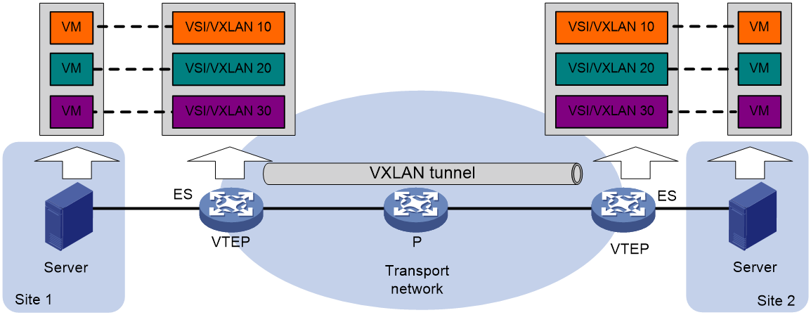
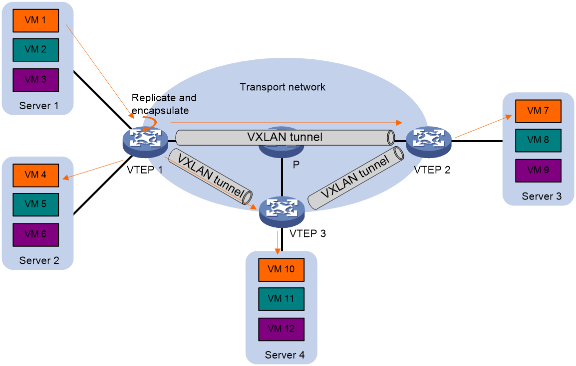
As shown in Figure 1, EVPN uses the VXLAN technology for traffic forwarding in the data plane. The transport edge devices assign VMs to different VXLANs, and then forward traffic between sites for VMs by using VXLAN tunnels. The transport edge devices are VXLAN tunnel endpoints (VTEPs). They can be servers that host VMs or independent network devices. The EVPN network sites and transport network can be IPv4 or IPv6 networks.
A VTEP uses ESs, VSIs, and VXLAN tunnels to provide VXLAN services:
· Ethernet segment (ES)—An ES is a link that connects a site to a VTEP. Each ES is uniquely identified by an Ethernet segment identifier (ESI).
· VSI—A virtual switch instance is a virtual Layer 2 switched domain. Each VSI provides switching services only for one VXLAN. VSIs learn MAC addresses and forward frames independently of one another. VMs in different sites have Layer 2 connectivity if they are in the same VXLAN. A VXLAN is identified by a 24-bit VXLAN ID which is also called the virtual network identifier (VNI). A VXLAN corresponds to an EVPN instance.
· VXLAN tunnel—A VXLAN tunnel is a logical point-to-point tunnel between VTEPs over the transport network. Each VXLAN tunnel can trunk multiple VXLANs.
All VXLAN processing is performed on VTEPs. The ingress VTEP encapsulates VXLAN traffic in the VXLAN, outer UDP, and outer IP headers, and forwards the traffic through VXLAN tunnels. The egress VTEP removes the VXLAN encapsulation and forwards the traffic to the destination. Transport network devices (for example, the P device in Figure 1) forward VXLAN traffic only based on the outer IP header of VXLAN packets.
Figure 1 EVPN VXLAN network model
Configuration automation
If EVPN is used for Layer 2 forwarding, VTEPs use the following BGP EVPN routes to discover VTEP neighbors, establish VXLAN tunnels, and assign the tunnels to VXLANs:
· IMET route—VTEPs advertise their VXLAN IDs through IMET routes. If two VTEPs have the same VXLAN ID, they automatically establish a VXLAN tunnel and assign the tunnel to the VXLAN.
· MAC/IP advertisement route—VTEPs advertise local MAC addresses and VXLAN IDs through MAC/IP advertisement routes. If two VTEPs have the same VXLAN ID, they automatically establish a VXLAN tunnel and assign the tunnel to the VXLAN.
If EVPN is used for Layer 3 forwarding, VTEPs use the following BGP EVPN routes to discover VTEP neighbors, establish VXLAN tunnels, and assign the tunnels to VXLANs:
· IMET route—VTEPs advertise the VXLAN IDs they have through IMET routes. If two VTEPs have the same VXLAN ID, they automatically establish a VXLAN tunnel and assign the tunnel to the VXLAN.
· MAC/IP advertisement route and IP prefix advertisement route—In the EVPN gateway deployment, VTEPs advertise MAC/IP advertisement routes or IP prefix advertisement routes which carry the export targets. When a VTEP receives a route, it compares the export targets of the route with the local import targets. If the route targets match, the VTEP establishes a VXLAN tunnel with the remote VTEP and associates the tunnel with the L3 VXLAN ID of the corresponding VPN instance. For more information about the L3 VXLAN ID, see "Distributed EVPN gateway deployment."
Assignment of traffic to VXLANs
Traffic from the local site to a remote site
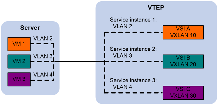
The VTEP uses an Ethernet service instance or Layer 3 interface to match customer traffic on a site-facing interface. The VTEP assigns customer traffic to a VXLAN by mapping the Layer 3 interface or Ethernet service instance to a VSI.
An Ethernet service instance or Layer 3 interface is identical to an attachment circuit (AC) in L2VPN.
An Ethernet service instance matches a list of VLANs on a Layer 2 Ethernet interface by using a frame match criterion. The frame match criterion specifies the characteristics of traffic from the VLANs, such as tagging status and VLAN IDs.
As shown in Figure 2, Ethernet service instance 1 matches VLAN 2 and is mapped to VSI A (VXLAN 10). When a frame from VLAN 2 arrives, the VTEP assigns the frame to VXLAN 10 and looks up VSI A's MAC address table for the outgoing interface.
Figure 2 Identifying traffic from the local site
Traffic from a remote site to the local site
When a VXLAN packet arrives at a VXLAN tunnel interface, the VTEP uses the VXLAN ID in the packet to identify its VXLAN.
Layer 2 forwarding
MAC learning
The VTEP performs Layer 2 forwarding based on a VSI's MAC address table. The VTEP learns MAC addresses by using the following methods:
· Local MAC learning—The VTEP automatically learns the source MAC addresses of frames sent from the local site. The outgoing interfaces of local MAC address entries are site-facing interfaces on which the MAC addresses are learned.
· Remote MAC learning—The VTEP uses MP-BGP to advertise local MAC reachability information to remote sites and learn MAC reachability information from remote sites. The outgoing interfaces of MAC address entries advertised from a remote site are VXLAN tunnel interfaces.
Unicast
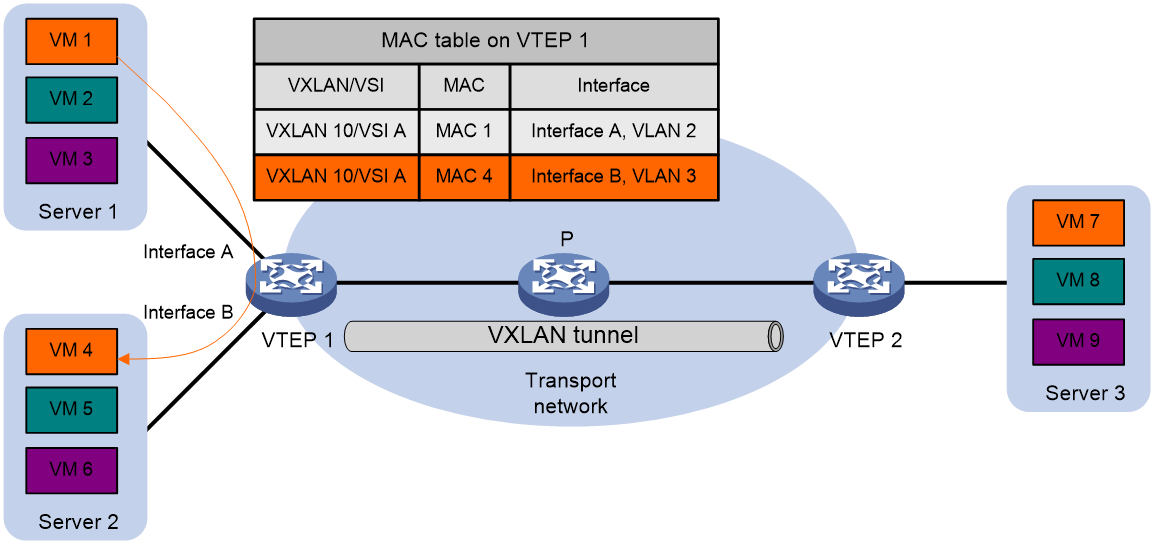
As shown in Figure 3, the VTEP performs typical Layer 2 forwarding for known unicast traffic within the local site.
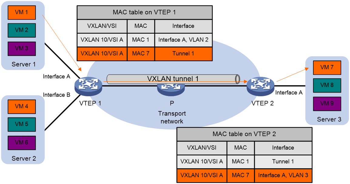
As shown in Figure 4, the following process applies to a known unicast frame between sites:
1. The source VTEP encapsulates the Ethernet frame in the VXLAN/UDP/IP header.
In the outer IP header, the source IP address is the source VTEP's VXLAN tunnel source IP address. The destination IP address is the VXLAN tunnel destination IP address.
2. The source VTEP forwards the encapsulated packet out of the outgoing VXLAN tunnel interface found in the VSI's MAC address table.
3. The intermediate transport devices (P devices) forward the packet to the destination VTEP by using the outer IP header.
4. The destination VTEP removes the headers on top of the inner Ethernet frame. It then performs MAC address table lookup in the VXLAN's VSI to forward the frame out of the matching outgoing interface.
Flood
As shown in Figure 5, a VTEP floods a broadcast, multicast, or unknown unicast frame to all site-facing interfaces and VXLAN tunnels in the VXLAN, except for the incoming interface. The source VTEP replicates the flood frame, and then sends one replica to the destination IP address of each VXLAN tunnel in the VXLAN. Each destination VTEP floods the inner Ethernet frame to all the site-facing interfaces in the VXLAN. To avoid loops, the destination VTEPs do not flood the frame to VXLAN tunnels.
Figure 5 Forwarding of flood traffic
Centralized EVPN gateway deployment
|
|
IMPORTANT: This section uses IPv4 sites as examples to describe the Layer 3 forwarding process of EVPN networks. The Layer 3 forwarding process does not differ between IPv4 and IPv6 sites. |
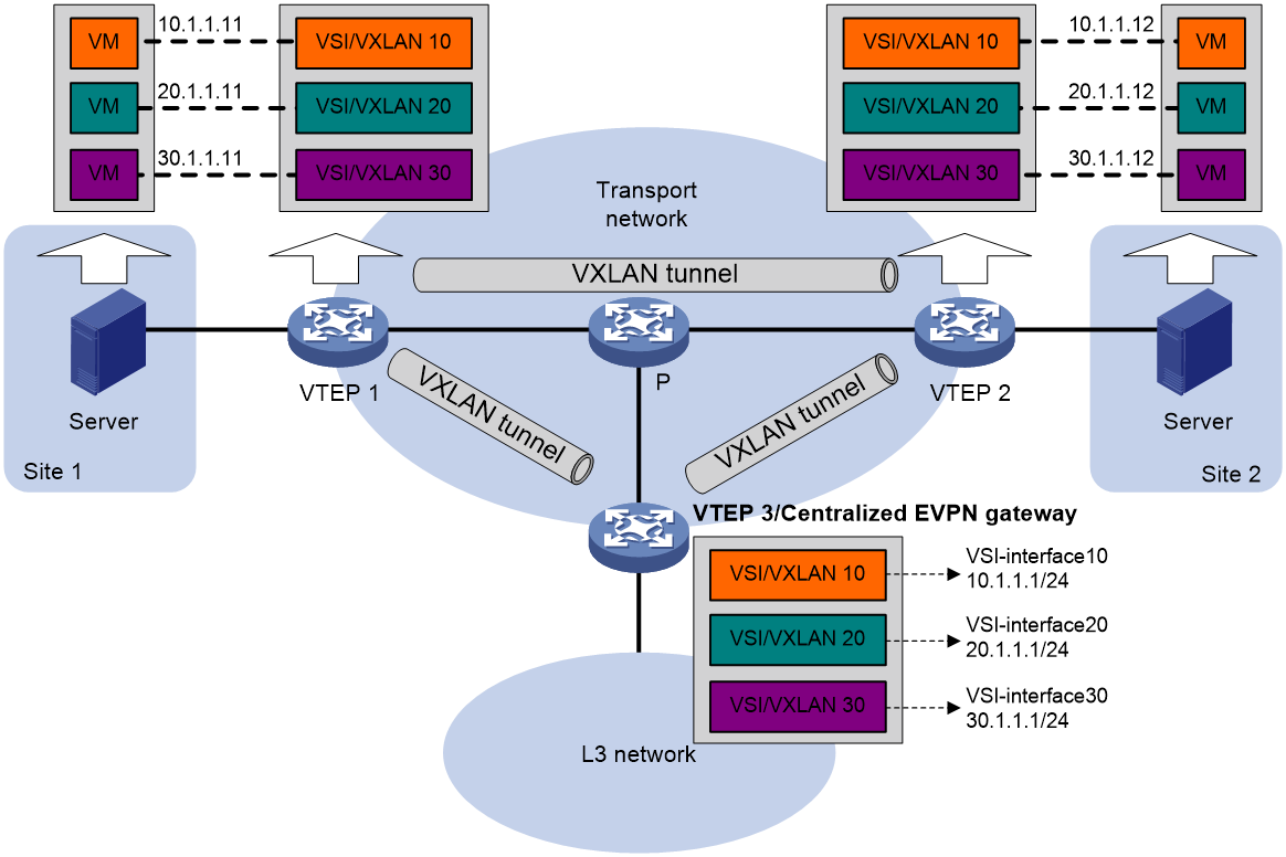
Centralized EVPN gateway deployment uses one VTEP to provide Layer 3 forwarding for VXLANs. The VTEP uses virtual Layer 3 VSI interfaces as gateway interfaces for VXLANs. Typically, the gateway-collocated VTEP connects to other VTEPs and the external network. To use this design, make sure the gateway has sufficient bandwidth and processing capability.
As shown in Figure 6, a VTEP acts as a gateway for VMs in the VXLANs. The VTEP both terminates the VXLANs and performs Layer 3 forwarding for the VMs. The network uses the following process to forward Layer 3 traffic from a VM to the destination:
1. The VM sends an ARP request to obtain the MAC address of the VSI interface that acts as the gateway, and then sends the Layer 3 traffic to the centralized EVPN gateway.
2. The local VTEP looks up the matching VSI's MAC address table and forwards the traffic to the centralized EVPN gateway through a VXLAN tunnel.
3. The centralized EVPN gateway removes the VXLAN encapsulation and forwards the traffic at Layer 3.
4. The centralized EVPN gateway forwards the replies sent by the destination node to the VM based on the ARP entry for the VM.
Figure 6 Example of centralized EVPN gateway deployment
Distributed EVPN gateway deployment
|
|
IMPORTANT: This section uses IPv4 sites as examples to describe the Layer 3 forwarding process of EVPN networks. The Layer 3 forwarding process does not differ between IPv4 and IPv6 sites. |
About distributed EVPN gateway deployment
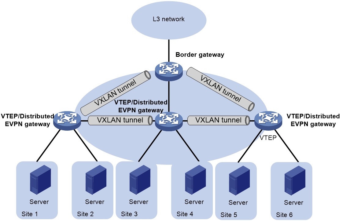
Distributed EVPN gateway deployment deploys one EVPN gateway on each VTEP to provide Layer 3 forwarding for VXLANs at their respective sites. The gateways use virtual Layer 3 VSI interfaces as gateway interfaces for VXLANs. This design distributes the Layer 3 traffic load across VTEPs. However, its configuration is more complex than the centralized EVPN gateway design. A distributed EVPN gateway can provide services for both IPv4 sites and IPv6 sites. This section uses IPv4 sites as examples to describe the Layer 3 forwarding process of EVPN networks.
As shown in Figure 7, each site's VTEP acts as a gateway to perform Layer 3 forwarding for the VXLANs of the local site. A VTEP acts as a border gateway to the Layer 3 network for the VXLANs.
Figure 7 Distributed EVPN gateway placement design
A distributed EVPN gateway supports the following traffic forwarding modes:
· Asymmetric IRB—The ingress gateway performs Layer 2 and Layer 3 lookups and the egress gateway performs only Layer 2 forwarding.
· Symmetric IRB—Both the ingress and egress gateways perform Layer 2 and Layer 3 lookups.
Symmetric IRB
Basic concepts
Symmetric IRB introduces the following concepts:
· L3 VXLAN ID—Also called L3 VNI. An L3 VXLAN ID identifies the traffic of a routing domain where devices have Layer 3 reachability. An L3 VXLAN ID is associated with one VPN instance. Distributed EVPN gateways use VPN instances to isolate traffic of different services on VXLAN tunnel interfaces.
· Router MAC address—Each distributed EVPN gateway has a unique router MAC address used for inter-gateway forwarding. The MAC addresses in the inner Ethernet header of VXLAN packets are router MAC addresses of distributed EVPN gateways.
VSI interfaces
As shown in Figure 8, each distributed EVPN gateway has the following types of VSI interfaces:
· VSI interface as a gateway interface of a VXLAN—The VSI interface acts as the gateway interface for VMs in a VXLAN. The VSI interface is associated with a VSI and a VPN instance. On different distributed EVPN gateways, the VSI interface of a VXLAN uses the same IP address to provide services.
· VSI interface associated with an L3 VXLAN ID—The VSI interface is associated with a VPN instance and assigned an L3 VXLAN ID. VSI interfaces associated with the same VPN instance share an L3 VXLAN ID.
A border gateway only has VSI interfaces that are associated with an L3 VXLAN ID.
Figure 8 Example of distributed EVPN gateway deployment
Layer 3 forwarding entry learning
A distributed EVPN gateway forwards Layer 3 traffic based on FIB entries generated from BGP EVPN routes and ARP information.
A VTEP advertises an external route imported in the EVPN address family through MP-BGP. A remote VTEP adds the route to the FIB table of a VPN instance based on the L3 VXLAN ID carried in the route. In the FIB entry, the outgoing interface is a VXLAN tunnel interface, and the next hop is the peer VTEP address in the NEXT_HOP attribute of the route.
A VTEP has the following types of ARP information:
· Local ARP information—ARP information of VMs in the local site. The VTEP snoops GARP packets, RARP packets, and ARP requests for the gateway MAC address to learn the ARP information of the senders and generates ARP entries and FIB entries. In an ARP or FIB entry, the outgoing interface is the site-facing interface where the packet is received, and the VPN instance is the instance associated with the corresponding VSI interface.
· Remote ARP information—ARP information of VMs in remote sites. Each VTEP uses MP-BGP to advertise its local ARP information with L3 VXLAN IDs in routes to remote sites. A VTEP generates only FIB entries for the remote ARP information. A FIB entry contains the following information:
¡ Outgoing interface: VSI interface associated with the L3 VXLAN ID.
¡ Next hop: Peer VTEP address in the NEXT_HOP attribute of the route.
¡ VPN instance: VPN instance associated with the L3 VXLAN ID.
The VTEP then creates an ARP entry for the next hop in the FIB entry.
Traffic forwarding
A distributed EVPN gateway can work in one of the following modes:
· Switching and routing mode—Forwards Layer 2 traffic based on the MAC address table and forwards Layer 3 traffic based on the FIB table. In this mode, you need to enable ARP or ND flood suppression on the distributed EVPN gateway to reduce flooding.
· Routing mode— Forwards both Layer 2 and Layer 3 traffic based on the FIB table. In this mode, you need to enable local proxy ARP on the distributed EVPN gateway.
For more information about MAC address table-based Layer 2 forwarding, see "Unicast."
Figure 9 shows the intra-site Layer 3 forwarding process.
1. The source VM sends an ARP request to obtain the MAC address of the destination VM.
2. The gateway replies to the source VM with the MAC address of the VSI interface associated with the source VM's VSI.
3. The source VM sends a Layer 3 packet to the gateway.
4. The gateway looks up the FIB table of the VPN instance associated with the source VM's VSI and finds the matching outgoing site-facing interface.
5. The gateway processes the Ethernet header of the Layer 3 packet as follows:
¡ Replaces the destination MAC address with the destination VM's MAC address.
¡ Replaces the source MAC address with the VSI interface's MAC address.
6. The gateway forwards the Layer 3 packet to the destination VM.
Figure 9 Intra-site Layer 3 forwarding
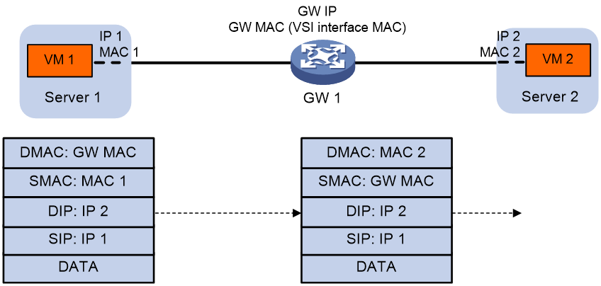
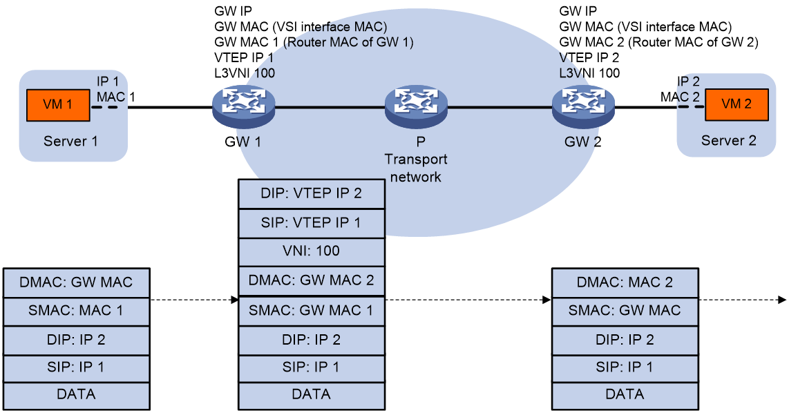
Figure 10 shows the inter-site Layer 3 forwarding process.
1. The source VM sends an ARP request to obtain the MAC address of the destination VM.
2. The gateway replies to the source VM with the MAC address of the VSI interface associated with the source VM's VSI.
3. The source VM sends a Layer 3 packet to the gateway.
4. The gateway looks up the FIB table of the VPN instance associated with the source VM's VSI and finds the matching outgoing VSI interface.
5. The gateway processes the Ethernet header of the Layer 3 packet as follows:
¡ Replaces the destination MAC address with the destination gateway's router MAC address.
¡ Replaces the source MAC address with its own router MAC address.
6. The gateway adds VXLAN encapsulation to the Layer 3 packet and forwards the packet to the destination gateway. The encapsulated VXLAN ID is the L3 VXLAN ID of the corresponding VPN instance.
7. The destination gateway identifies the VPN instance of the packet based on the L3 VXLAN ID and removes the VXLAN encapsulation. Then the gateway forwards the packet based on the matching ARP entry.
Figure 10 Inter-site Layer 3 forwarding
Communication between private and public networks
A distributed EVPN gateway uses the public instance to perform Layer 3 forwarding for the public network and to enable communication between private and public networks. The public instance is similar to a VPN instance. A distributed EVPN gateway processes traffic of the public instance in the same way it does for a VPN instance. For the public instance to work correctly, you must configure an RD, an L3 VXLAN ID, and route targets for it. If a VSI interface is not associated with any VPN instance, the VSI interface belongs to the public instance.
Asymmetric IRB
VSI interfaces
Asymmetric IRB uses the same distributed EVPN gateway deployment as symmetric IRB.
As shown in Figure 8, each distributed EVPN gateway has the following types of VSI interfaces:
· VSI interface as a gateway interface of a VXLAN—The VSI interface is associated with a VSI and a VPN instance. On different distributed EVPN gateways, the VSI interface of a VXLAN must use different IP addresses to provide services.
· VSI interface associated with an L3 VXLAN ID—The VSI interface acts as the gateway for VMs in a VXLAN to communicate with the external network through the border gateway. The VSI interface is associated with a VPN instance and assigned an L3 VXLAN ID. VSI interfaces associated with the same VPN instance share an L3 VXLAN ID.
A border gateway only has VSI interfaces that are associated with an L3 VXLAN ID.
Layer 3 forwarding
Asymmetric IRB supports only Layer 3 forwarding in the same VXLAN on distributed EVPN gateways.
After a distributed EVPN gateway learns ARP information about local VMs, it advertises the information to other distributed EVPN gateways through MAC/IP advertisement routes. Other distributed EVPN gateways generate FIB entries based on the advertised ARP information.
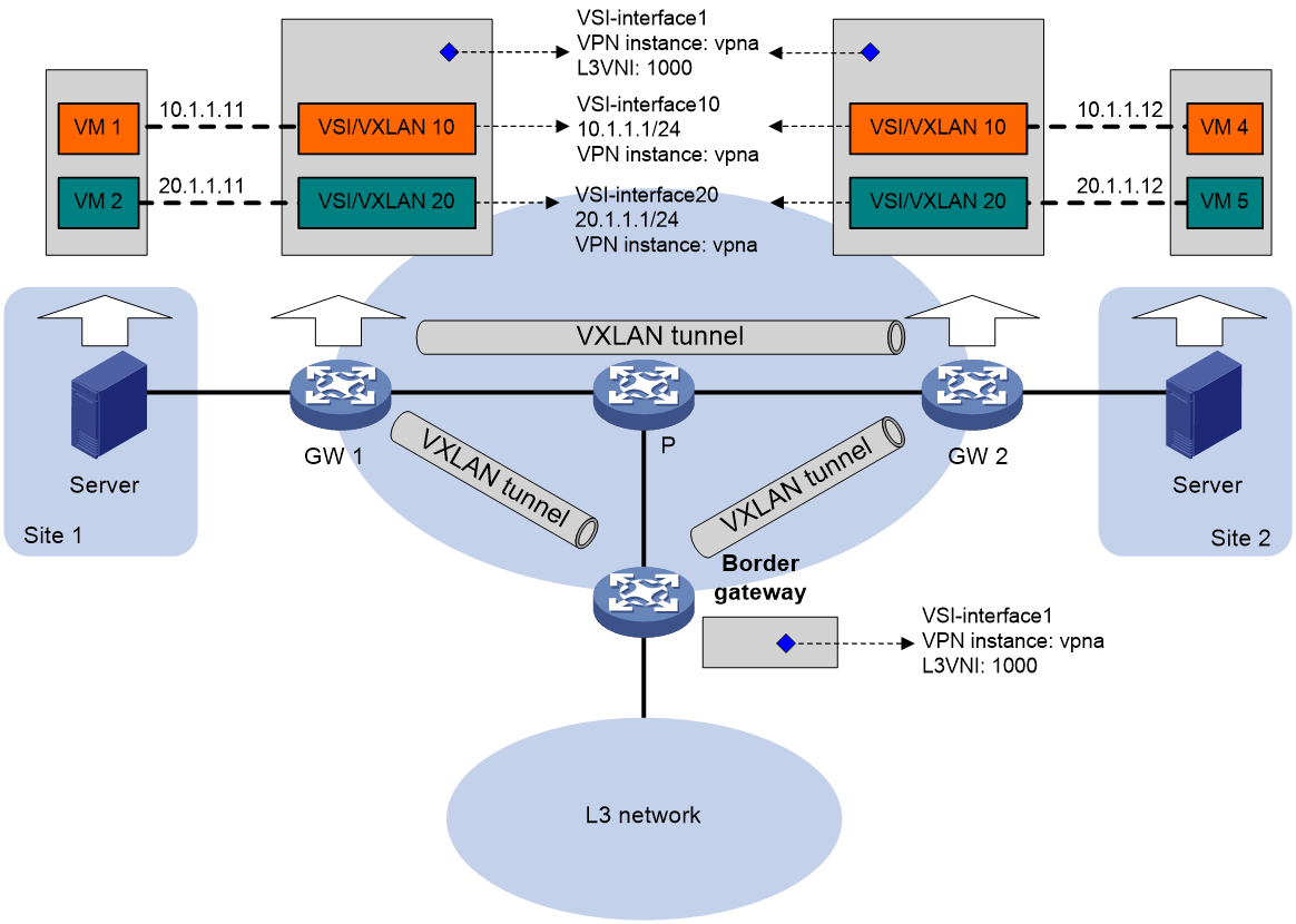
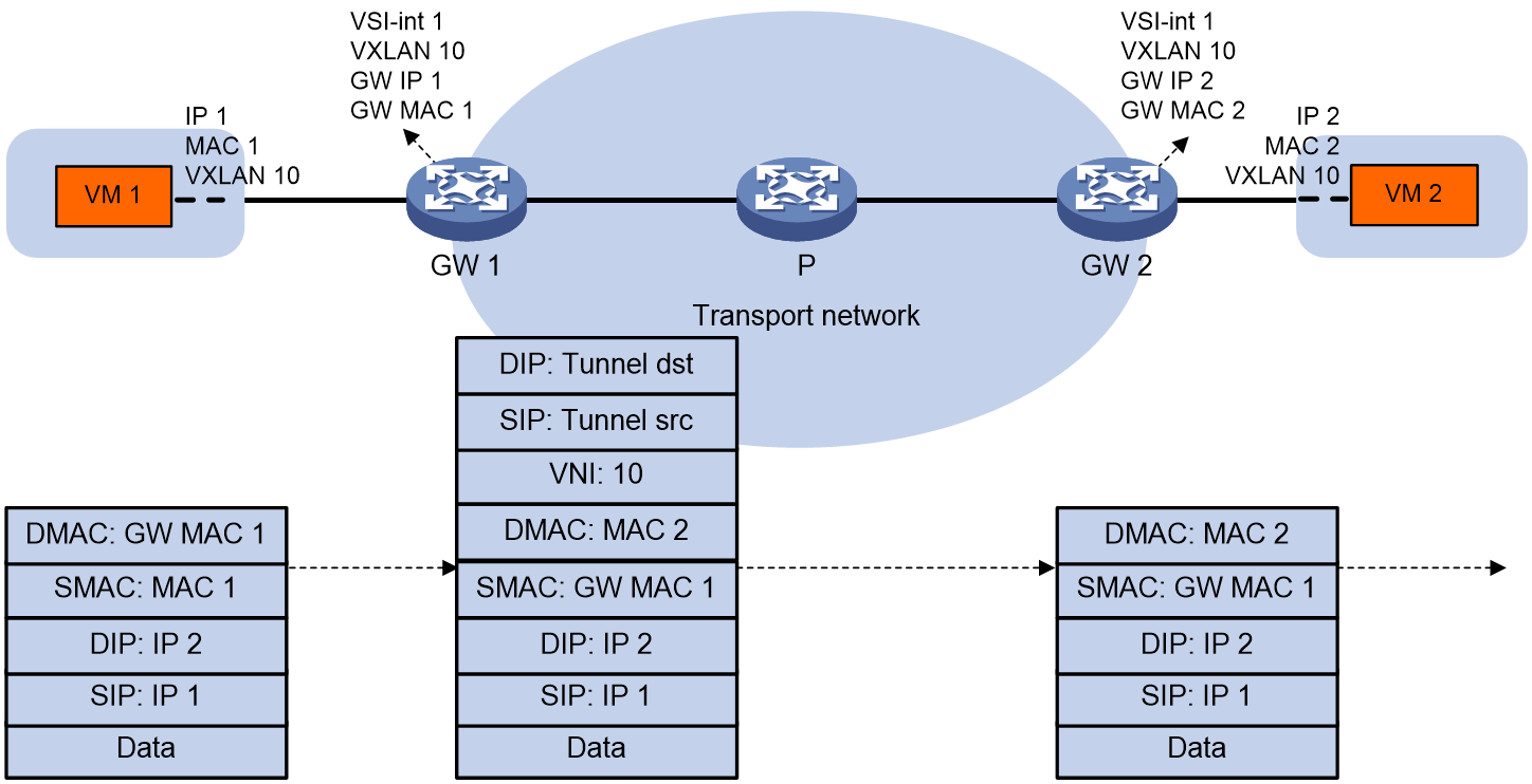
As shown in Figure 11, VM 1 and VM 2 belong to VXLAN 10 and they can reach each other at Layer 3 through the distributed EVPN gateways. The distributed EVPN gateways use the following process to perform Layer 3 forwarding in asymmetric IRB mode when VM 1 sends a packet to VM 2:
1. After GW 1 receives the packet from VM 1, it finds that the destination MAC address is itself. Then, GW 1 removes the Layer 2 frame header and looks up the FIB table for the destination IP address.
2. GW 1 matches the packet to the FIB entry generated based on the ARP information of VM 2.
3. GW 1 encapsulates the packet source and destination MAC addresses as the MAC addresses of GW 1 and VM 2, respectively. Then, GW 1 adds VXLAN encapsulation to the packet and forwards the packet to GW 2 through a VXLAN tunnel.
4. GW 2 removes the VXLAN encapsulation from the packet, and performs Layer 2 forwarding in VXLAN 10 by looking up the MAC address table for the destination MAC address.
5. GW 2 forwards the packet to VM 2 based on the MAC address table lookup result.
Figure 11 Layer 3 forwarding in the same VXLAN (asymmetric IRB)
EVPN VXLAN multihoming
|
|
IMPORTANT: EVPN multihoming supports only IPv4 underlay networks. |
About EVPN VXLAN multihoming
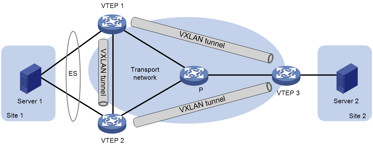
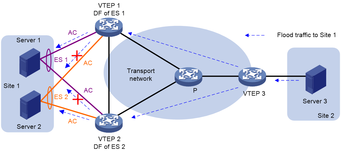
As shown in Figure 12, EVPN supports deploying multiple VTEPs at a site for redundancy and high availability. On the redundant VTEPs, Ethernet links connected to the site form an Ethernet segment (ES) that is uniquely identified by an Ethernet segment identifier (ESI).
Figure 12 EVPN VXLAN multihoming
DF election
To prevent redundant VTEPs from sending duplicate flood traffic to a multihomed site, a designated forwarder (DF) is elected from the VTEPs to forward flood traffic to the site. VTEPs that fail the election are assigned the backup designated forwarder (BDF) role. BDFs do not forward flood traffic to the site.
Redundant VTEPs at a site send Ethernet segment routes to one another to advertise ES and VTEP IP mappings. A VTEP accepts the Ethernet segment routes only when it is configured with an ESI. Then, the VTEPs select a DF for each AC based on the ES and VTEP IP mappings. DF election can be performed by using a VLAN tag-based algorithm or preference-based algorithm.
VLAN tag-based DF election
VTEPs select a DF for each AC based on the VLAN tag and VTEP IP address as follows:
1. Arrange source IP addresses in Ethernet segment routes with the same ESI in ascending order and assign a sequence number to each IP address, starting from 0.
2. Divide the lowest VLAN ID permitted on an AC by the number of the redundant VTEPs, and match the reminder to the sequence numbers of IP addresses.
3. Assign the DF role to the VTEP that uses the IP address with the matching sequence number.
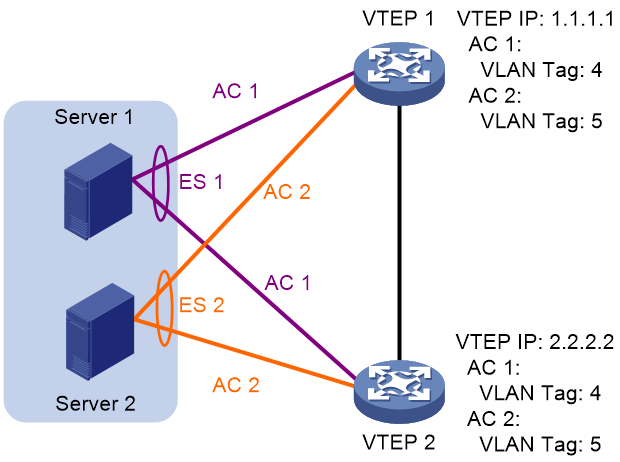
The following uses AC 1 in Figure 14 as an example to explain the DF election procedure:
1. VTEP 1 and VTEP 2 send Ethernet segment routes to each other.
2. The VTEPs assign sequence numbers 0 and 1 to IP addresses 1.1.1.1 and 2.2.2.2 in the Ethernet segment routes, respectively.
3. The VTEPs divide 4 (the lowest VLAN ID permitted by AC 1) by 2 (the number of redundant VTEPs), and match the reminder 0 to the sequence numbers of the IP addresses.
4. The DF role is assigned to VTEP 1 at 1.1.1.1.
Figure 14 VLAN tag-based DF election
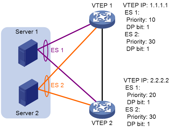
Preference-based DF election
VTEPs select a DF for each ES based on the DF election preference, the Don't Preempt Me (DP) bit in Ethernet segment routes, and VTEP IP address. The DP bit can be set to one of the following values:
· 1—DF preemption is disabled. A DF retains its role when a new DF is elected.
· 0—DF preemption is enabled.
Preference-based DF election uses the following rules to select a DF for an ES:
· The VTEP with higher preference becomes the DF.
· If two VTEPs have the same preference, the VTEP with the DP bit set to 1 becomes the DF. If both of the VTEPs have the DP bit set to 1, the VTEP with a lower IP address becomes the DF.
As shown in Figure 15, VTEP 2 is the DF for ES 1, and VTEP 1 is the DF for ES 2.
Figure 15 Preference-based DF election
Split horizon
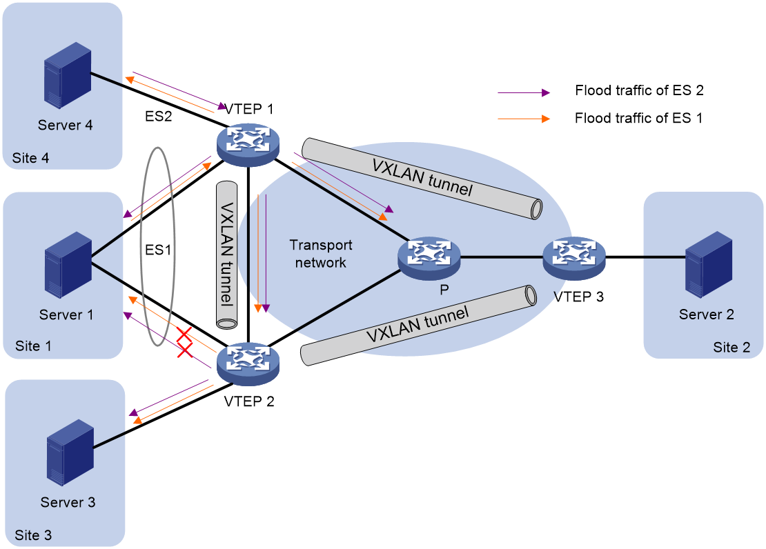
In a multihomed site, a VTEP forwards multicast, broadcast, and unknown unicast frames received from ACs out of all site-facing interfaces and VXLAN tunnels in the corresponding VXLAN, except for the incoming interface. As a result, the other VTEPs at the site receive these flood frames and forward them to site-facing interfaces, which causes duplicate floods and loops. EVPN introduces split horizon to resolve this issue. Split horizon disables a VTEP to forward flood traffic received from another local VTEP to site-facing interfaces if an ES on that local VTEP has the same ESI as these interfaces. As shown in Figure 16, both VTEP 1 and VTEP 2 have ES 1. When receiving flood traffic from VTEP 1, VTEP 2 does not forward the traffic to interfaces with ESI 1.
Redundancy mode
The device supports the all-active redundancy mode of EVPN VXLAN multihoming. This mode allows all redundant VTEPs at a multihomed site to forward broadcast, multicast, and unknown unicast traffic.
· For flood frames received from remotes sites, a VTEP forwards them to the ACs of which it is the DF.
· For flood frames received from the local site, a VTEP forwards them out of all site-facing interfaces and VXLAN tunnels in the corresponding VXLAN, except for the incoming interfaces. For flood frames to be sent out of a VXLAN tunnel interface, a VTEP replicates each flood frame and sends one replica to all the other VTEPs in the corresponding VXLAN.
IP aliasing
In all-active redundancy mode, all redundant VTEPs of an ES advertise the ES to remote VTEPs through MP-BGP. IP aliasing allows a remote VTEP to add the IP addresses of all the redundant VTEPs as the next hops for the MAC or ARP information received from one of these VTEPs. This mechanism creates ECMP routes between the remote VTEP and the redundant VTEPs.
ARP and ND flood suppression
ARP or ND flood suppression reduces ARP request broadcasts or ND request multicasts by enabling the VTEP to reply to ARP or ND requests on behalf of VMs.
As shown in Figure 17, this feature snoops ARP or ND requests, ARP or ND responses, and BGP EVPN routes to populate the ARP or ND flood suppression table with local and remote MAC addresses. If an ARP or ND request has a matching entry, the VTEP replies to the request on behalf of the VM. If no match is found, the VTEP floods the request to both local and remote sites.
Figure 17 ARP and ND flood suppression
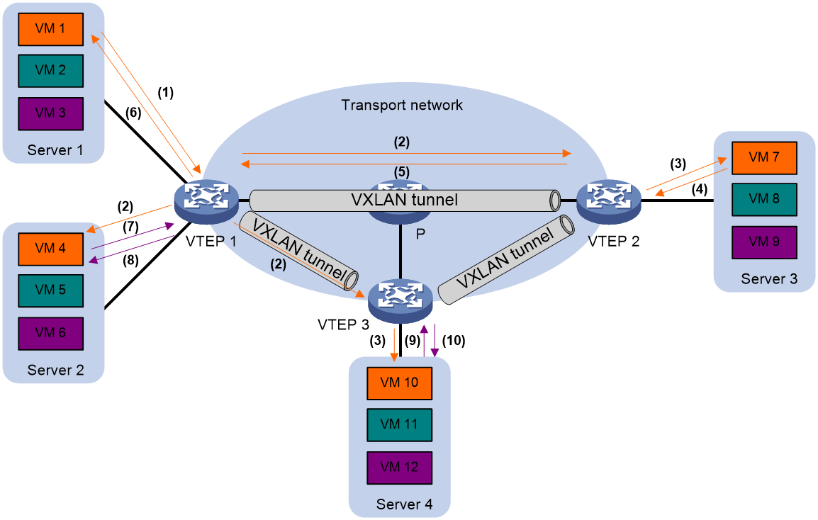
The following uses ARP flood suppression as an example to explain the flood suppression workflow:
1. VM 1 sends an ARP request to obtain the MAC address of VM 7.
2. VTEP 1 creates a suppression entry for VM 1, floods the ARP request in the VXLAN, and sends the suppression entry to VTEP 2 and VTEP 3 through BGP EVPN.
3. VTEP 2 and VTEP 3 de-encapsulate the ARP request and broadcast the request in the local site.
4. VM 7 sends an ARP reply.
5. VTEP 2 creates a suppression entry for VM 7, forwards the ARP reply to VTEP 1, and sends the suppression entry to VTEP 1 and VTEP 3 through BGP EVPN.
6. VTEP 1 de-encapsulates the ARP reply and forwards the ARP reply to VM 1.
7. VM 4 sends an ARP request to obtain the MAC address of VM 1.
8. VTEP 1 creates a suppression entry for VM 4 and replies to the ARP request.
9. VM 10 sends an ARP request to obtain the MAC address of VM 1.
10. VTEP 3 creates a suppression entry for VM 10 and replies to the ARP request.
MAC mobility
MAC mobility refers to the movement of a VM or host from one ES to another. The source VTEP is unaware of the MAC move event. To notify other VTEPs of the change, the destination VTEP advertises a MAC/IP advertisement route for the MAC address. The source VTEP withdraws the old route for the MAC address after receiving the new route. The MAC/IP advertisement route has a sequence number that increases when the MAC address moves. The sequence number identifies the most recent move if the MAC address moves multiple times.
Configuring EVPN VXLAN
EVPN VXLAN tasks at a glance
To configure EVPN VXLAN, perform the following tasks:
1. Configuring a VXLAN on a VSI
a. Configuring a VXLAN on a VSI
b. (Optional.) Configuring VSI parameters
2. Configuring an EVPN instance
3. (Optional.) Configuring EVPN VXLAN multihoming
b. (Optional.) Configuring the DF election algorithm
c. (Optional.) Setting the DF election delay
d. (Optional.) Disabling advertisement of EVPN multihoming routes
e. (Optional.) Enabling the device to ignore the Ethernet tag when advertising Ethernet auto-discovery routes and MAC/IP advertisement routes
f. (Optional.) Enabling the device to monitor the BGP peer status of another local edge device
4. Configuring BGP to advertise BGP EVPN routes
a. Enabling BGP to advertise BGP EVPN routes
b. (Optional.) Configuring attributes of BGP EVPN routes
c. (Optional.) Configuring optimal BGP EVPN route selection
d. (Optional.) Configuring BGP route reflection
e. (Optional.) Filtering BGP EVPN routes
f. (Optional.) Advertising BGP RPKI validation state to a peer or peer group
g. (Optional.) Configuring BGP soft-reset by saving route updates
h. (Optional.) Maintaining BGP sessions
6. Configuring an EVPN gateway
Choose one of the following tasks:
¡ Configuring a centralized EVPN gateway
¡ Configuring a distributed EVPN gateway
7. (Optional.) Managing MAC address entries and ARP learning
8. (Optional.) Configuring BGP EVPN route redistribution and advertisement
¡ Redistributing MAC/IP advertisement routes into BGP unicast routing tables
¡ Setting the metric of BGP EVPN routes added to a VPN instance's routing table
¡ Enabling BGP EVPN route advertisement to the local site
9. (Optional.) Interconnecting an EVPN VXLAN network with a heterogeneous network
¡ Interconnecting an EVPN VXLAN network with a VPLS network
¡ Interconnecting an EVPN VXLAN network with an EVPN VPLS network
10. (Optional.) Maintaining and optimizing an EVPN network
¡ Confining floods to the local site
¡ Enabling ARP or ND flood suppression
¡ Enabling packet statistics for VXLAN tunnels
¡ Enabling SNMP notifications for EVPN
Restrictions and guidelines: EVPN VXLAN configuration
EVPN VXLAN is available only on the following cards:
|
Card category |
Cards |
|
CEPC |
CEPC-XP4LX, CEPC-XP24LX, CEPC-XP48RX, CEPC-CP4RX, CEPC-CP4RXA, CEPC-CP4RX-L, CEPC-CQ8L, CEPC-CQ8LA, CEPC-CQ16L1 |
|
CSPEX |
CSPEX-1304X, CSPEX-1404X, CSPEX-1502X, CSPEX-1504X, CSPEX-1504XA, CSPEX-1602X, CSPEX-1602XA, CSPEX-1804X, CSPEX-1512X, CSPEX-1612X, CSPEX-1812X, CSPEX-1802X, CSPEX-1802XA, CSPEX-2612XA, CSPEX-1812X-E, CSPEX-2304X-G, CSPEX-1502XA |
|
SPE |
RX-SPE200, RX-SPE200-E |
QoS policies and PBR are supported by VSI interfaces. Do not use the if-match command to configure the following match criteria for the QoS policies:
· Matches an ACL that contains the VPN instance criterion.
· Matches an authentication user or destination MAC address.
· Matches a Layer 2 ACL that contains the destination MAC address criterion.
On an EVPN gateway, ACs do not support Ethernet access mode.
You cannot configure both the gateway interface setting and L3 VXLAN ID association on a VSI interface.
Make sure the following VXLAN tunnels are not associated with the same VXLAN if they have the same tunnel destination IP address:
· A VXLAN tunnel automatically created by EVPN.
· A manually created VXLAN tunnel.
For more information about manual tunnel configuration, see VXLAN Configuration Guide.
As a best practice to ensure correct traffic forwarding, configure the same MAC address for all VSI interfaces on an EVPN gateway.
Configuring a VXLAN on a VSI
Restrictions and guidelines for VXLAN configuration on a VSI
For more information about the VXLAN commands in this task, see VXLAN Command Reference.
Creating a VXLAN on a VSI
1. Enter system view.
system-view
2. Enable L2VPN.
l2vpn enable
By default, L2VPN is disabled.
3. Create a VSI and enter VSI view.
vsi vsi-name
4. Enable the VSI.
undo shutdown
By default, a VSI is enabled.
5. Create a VXLAN and enter VXLAN view.
vxlan vxlan-id
You can create only one VXLAN on a VSI. The VXLAN ID must be unique for each VSI.
Configuring VSI parameters
1. Enter system view.
system-view
2. Enter VSI view.
vsi vsi-name
3. Configure a VSI description.
description text
By default, a VSI does not have a description.
4. Set the MTU for the VSI.
mtu mtu
The default MTU is 1500 bytes for a VSI.
5. Set the maximum bandwidth for known unicast traffic of the VSI.
bandwidth bandwidth
By default, the maximum bandwidth is not limited for known unicast traffic of a VSI.
6. Set the broadcast, multicast, or unknown unicast bandwidth restraints for the VSI.
restrain { broadcast | multicast | unknown-unicast } bandwidth
By default, the broadcast, multicast, and unknown unicast bandwidth restraints are 5120 kbps on a VSI.
7. Configure MAC address learning settings:
a. Enable MAC address learning for the VSI.
mac-learning enable
By default, MAC address learning is enabled for a VSI.
b. (Optional.) Set a limit for the VSI's MAC address table.
mac-table limit mac-limit
By default, no limit is set for a VSI's MAC address table.
c. (Optional.) Enable the VSI to drop source-unknown unicast frames if the MAC address table is full.
mac-table limit drop-unknown
By default, the VSI forwards source-unknown unicast frames without learning the source MAC address if the MAC address table is full.
Configuring an EVPN instance
About EVPN instance configuration
If a VXLAN requires only Layer 2 connectivity, you do not need to associate a VPN instance with it. The BGP EVPN routes advertised by a VTEP carry the RD and route targets configured for the EVPN instance associated with the VXLAN.
Use one of the following methods to create an EVPN instance:
· Create an EVPN instance in system view—You can bind an EVPN instance created in system view to multiple VSIs to simplify configuration.
· Create an EVPN instance on a VSI—An EVPN instance created in VSI view is automatically bound with the VSI.
In EVPN instance view, you can configure routing policies to filer the routes redistributed from BGP EVPN to an EVPN instance and vice versa.
Restrictions and guidelines for EVPN instance configuration
If you have created an EVPN instance in VSI view for a VSI, you cannot bind the VSI to an EVPN instance created in system view. If you have bound a VSI to an EVPN instance created in system view, you cannot create an EVPN instance in VSI view for the VSI.
Configuring an EVPN instance created in system view
1. Enter system view.
system-view
2. Create an EVPN instance and enter its view.
evpn instance instance-name
3. Configure an RD for the EVPN instance.
route-distinguisher route-distinguisher
By default, no RD is configured for an EVPN instance.
4. Configure route targets for the EVPN instance.
vpn-target vpn-target&<1-8> [ both | export-extcommunity | import-extcommunity ]
By default, an EVPN instance does not have route targets.
Make sure the following requirements are met:
¡ The export targets of the EVPN instance do not match the export targets configured for another EVPN instance in system view, VSI view, VPN instance view, public instance view, or cross-connect group view.
¡ The import targets configure for the EVPN instance in VPN instance view, public instance view, or other views do not match the export targets of a cross-connect group EVPN instance.
For more information about VPN instance configuration and public instance configuration, see "Configuring an L3 VXLAN ID for a VSI interface."
5. (Optional.) Apply an export routing policy to the EVPN instance.
export route-policy route-policy
By default, no export routing policy is applied to an EVPN instance.
6. (Optional.) Apply an import routing policy to the EVPN instance.
import route-policy route-policy
By default, no import routing policy is applied to an EVPN instance.
7. Return to system view.
quit
8. Enter VSI view.
vsi vsi-name
9. Bind the VSI to the EVPN instance.
evpn encapsulation vxlan binding instance instance-name vsi-tag { tag-id | auto-vxlan }
By default, a VSI is not bound to an EVPN instance created in system view.
You can bind a VSI to one or two EVPN instances. If you bind two EVP instances to a VSI, make sure one EVPN instance uses MPLS encapsulation and the other uses VXLAN encapsulation.
Configuring an EVPN instance created in VSI view
1. Enter system view.
system-view
2. Enter VSI view.
vsi vsi-name
3. Create an EVPN instance and enter VSI EVPN instance view.
evpn encapsulation vxlan
4. Configure an RD for the EVPN instance.
route-distinguisher { route-distinguisher | auto [ router-id ] }
By default, no RD is configured for an EVPN instance.
5. Configure route targets for the EVPN instance.
vpn-target { vpn-target&<1-8> | auto } [ both | export-extcommunity | import-extcommunity ]
By default, an EVPN instance does not have route targets.
Make sure the following requirements are met:
¡ The export targets of the EVPN instance do not match the export targets configured for another EVPN instance in system view, VSI view, VPN instance view, public instance view, or cross-connect group view.
¡ The import targets configure for the EVPN instance in VPN instance view, public instance view, or other views do not match the export targets of a cross-connect group EVPN instance.
For more information about VPN instance configuration and public instance configuration, see "Configuring an L3 VXLAN ID for a VSI interface."
Configuring EVPN VXLAN multihoming
Restrictions and guidelines for EVPN VXLAN multihoming
In a multihomed site, AC configuration and VXLAN IDs must be consistent on redundant VTEPs of the same ES. For each VXLAN ID, you must configure unique RDs for the EVPN instance of VSIs on the redundant VTEPs. You must configure different RDs for the VPN instances and the public instance that use the same VXLAN IP gateway.
You can assign ESIs to a main interface and its subinterfaces.
· If you assign an ESI to a subinterface, the subinterface-specific ESI and ES configuration take precedence over those configured on the main interface. The ES configuration includes the following:
¡ evpn df-election algorithm.
¡ evpn df-election preference.
¡ evpn df-election preference non-revertive.
¡ evpn timer es-delay.
· If you do not assign an ESI to a subinterface, it inherits the ESI and ES configuration (if configured) of the main interface. In this scenario, the ES configuration on the subinterface does not take effect.
Configuring an ESI
About this task
An ESI uniquely identifies an ES. The links on interfaces (or VSIs) with the same ESI belong to the same ES. Traffic of the ES can be distributed among the links for load sharing.
Assigning an ESI to an interface
1. Enter system view.
system-view
2. Enter interface view.
¡ Enter Layer 2 Ethernet interface view.
interface interface-type interface-number
¡ Enter Layer 2 aggregate interface view.
interface bridge-aggregation interface-number
¡ Enter Layer 3 Ethernet interface view.
interface interface-type interface-number
¡ Enter Layer 3 aggregate interface view.
interface route-aggregation interface-number
¡ Enter FlexE physical interface view.
interface interface-type interface-number
¡ Enter FlexE interface view.
interface flexe interface-number
3. Assign an ESI to the interface.
esi esi-id
By default, no ESI is assigned to an interface.
Assigning an ESI to a VSI
1. Enter system view.
system-view
2. Enter VSI view.
vsi vsi-name
3. Assign an ESI to the VSI.
esi esi-id
By default, no ESI is assigned to a VSI.
Configuring the DF election algorithm
About this task
At a multihomed EVPN network site, you can modify the DF election algorithm to control the DF election result.
Restrictions and guidelines
If the ambiguous VLAN termination is configured on a subinterface acting as an AC, do not use the VLAN tag-based DF election algorithm. If you use the algorithm, traffic forwarding errors might occur.
You can configure the DF election algorithm in system view and in interface view. The global DF election algorithm takes effect on all ESs, and the interface-specific DF election algorithm takes effect only on the ESs on an interface. The interface-specific DF election algorithm takes precedence over the global DF election algorithm.
Configuring the DF election algorithm globally
1. Enter system view.
system-view
2. Configure the DF election algorithm.
evpn df-election algorithm algorithm
By default, the VLAN tag-based algorithm is used for DF election.
Configuring the DF election algorithm on an interface
1. Enter system view.
system-view
2. Enter interface view.
¡ Enter Layer 2 Ethernet interface view.
interface interface-type interface-number
¡ Enter Layer 2 aggregate interface view.
interface bridge-aggregation interface-number
¡ Enter Layer 3 Ethernet interface view.
interface interface-type interface-number
¡ Enter Layer 3 aggregate interface view.
interface route-aggregation interface-number
¡ Enter FlexE physical interface view.
interface interface-type interface-number
¡ Enter FlexE interface view.
interface flexe interface-number
3. Configure the DF election algorithm.
evpn df-election algorithm algorithm
By default, the DF election algorithm specified in system view takes effect.
Configuring preference-based DF election
1. Enter system view.
system-view
2. Enter interface view.
¡ Enter Layer 2 Ethernet interface view.
interface interface-type interface-number
¡ Enter Layer 2 aggregate interface view.
interface bridge-aggregation interface-number
¡ Enter Layer 3 Ethernet interface view.
interface interface-type interface-number
¡ Enter Layer 3 aggregate interface view.
interface route-aggregation interface-number
¡ Enter FlexE physical interface view.
interface interface-type interface-number
¡ Enter FlexE interface view.
interface flexe interface-number
3. Set the DF election preference.
evpn df-election preference preference
By default, the DF election preference is 32767.
The larger the value, the higher the preference.
4. (Optional.) Enable non-revertive mode for preference-based DF election.
evpn df-election preference non-revertive
By default, non-revertive mode is disabled for preference-based DF election.
Setting the DF election delay
About this task
The DF election can be triggered by site-facing interface status changes, redundant VTEP membership changes, and interface ESI changes. To prevent frequent DF elections from degrading network performance, set the DF election delay. The DF election delay defines the minimum interval allowed between two DF elections.
Procedure
1. Enter system view.
system-view
2. Set the DF election delay.
evpn multihoming timer df-delay delay-value
By default, the DF election delay is 3 seconds.
Disabling advertisement of EVPN multihoming routes
About this task
EVPN multihoming routes include Ethernet auto-discovery routes and Ethernet segment routes.
In a multihomed EVPN network, perform this task on a redundant VTEP before you reboot it. This operation allows other VTEPs to refresh their EVPN routing table to prevent traffic interruption caused by the reboot.
Procedure
1. Enter system view.
system-view
2. Disable advertisement of EVPN multihoming routes and withdraw the EVPN multihoming routes that have been advertised to remote sites.
evpn multihoming advertise disable
By default, the device advertises EVPN multihoming routes.
Enabling the device to ignore the Ethernet tag when advertising Ethernet auto-discovery routes and MAC/IP advertisement routes
About this task
This task enables the device to withdraw the Ethernet auto-discovery routes and MAC/IP advertisement routes that have been advertised, set their Ethernet tag field to 0, and then re-advertise them.
After you configure ESIs for ACs on the redundant edge devices at a dualhomed site, the edge devices advertise Ethernet auto-discovery routes and MAC/IP advertisement routes that carry Ethernet tags. If the remote peers are unable to identify Ethernet tags, you must perform this task on the redundant edge devices to enable communication with the peers.
Restrictions and guidelines
After you assign an ESI to a Layer 2 Ethernet or aggregate interface, you must map the Ethernet service instances created on the interface to different VSIs. If two interfaces use the same ESI, you must map the Ethernet service instances created on them to different VSIs.
After you assign an ESI to a Layer 3 main interface, its subinterfaces inherit the ESI if they do not have one. In addition, you must map two subinterfaces to different VSIs if the subinterfaces have the same ESI.
Procedure
1. Enter system view.
system-view
2. Enable the device to ignore the Ethernet tag when advertising Ethernet auto-discovery routes and MAC/IP advertisement routes.
evpn multihoming advertise ignore-ethernet-tag
By default, the device advertises Ethernet auto-discovery routes and MAC/IP advertisement routes that carry Ethernet tags.
Enabling the device to monitor the BGP peer status of another local edge device
About this task
Perform this task on the CE-facing interfaces of the edge devices multihomed to a site to prevent device reboots from causing inter-site forwarding failure.
This task excludes unavailable edge devices from DF election at a multihomed site. After an edge device recovers from failure and brings up its CE-facing interface, it starts the advertisement delay timer for Ethernet segment routes and checks the status of the BGP peer specified in the evpn track peer command. If the BGP peer comes up before the timer expires, the edge device advertises Ethernet segment routes to the peer. If the BGP peer is still down when the timer expires, the edge device does not advertise Ethernet segment routes to the peer. The edge devices then perform DF election based on the Ethernet segment routes they have received.
Procedure
1. Enter system view.
system-view
2. Enter interface view.
¡ Enter Layer 2 Ethernet interface view.
interface interface-type interface-number
¡ Enter Layer 2 aggregate interface view.
interface bridge-aggregation interface-number
¡ Enter Layer 3 Ethernet interface view.
interface interface-type interface-number
¡ Enter Layer 3 aggregate interface view.
interface route-aggregation interface-number
¡ Enter FlexE physical interface view.
interface interface-type interface-number
¡ Enter FlexE interface view.
interface flexe interface-number
3. Enable the device to monitor the BGP peer status of another local edge device.
evpn track peer peer-address
By default, the device does not monitor the BGP peer status of the other edge devices at a multihomed site.
4. Set the advertisement delay timer for Ethernet segment routes.
evpn timer es-delay delay-time
By default, advertisement of Ethernet segment routes is not delayed.
Configuring BGP to advertise BGP EVPN routes
Restrictions and guidelines for BGP EVPN route advertisement
The device can send the BGP EVPN routes received from an IPv4 peer to an IPv6 peer, and vice versa.
For more information about BGP commands in this task, see Layer 3—IP Routing Command Reference.
Enabling BGP to advertise BGP EVPN routes
1. Enter system view.
system-view
2. Configure a global router ID.
router id router-id
By default, no global router ID is configured.
3. Enable a BGP instance and enter BGP instance view.
bgp as-number [ instance instance-name ]
By default, BGP is disabled and no BGP instances exist.
4. Specify remote VTEPs as BGP peers.
peer { group-name | ipv4-address [ mask-length ] | ipv6-address [ prefix-length ] } as-number as-number
5. Create the BGP EVPN address family and enter BGP EVPN address family view.
address-family l2vpn evpn
6. Enable BGP to exchange BGP EVPN routes with a peer or peer group.
peer { group-name | ipv4-address [ mask-length ] | ipv6-address [ prefix-length ] } enable
By default, BGP does not exchange BGP EVPN routes with peers.
Configuring attributes of BGP EVPN routes
1. Enter system view.
system-view
2. Enter BGP instance view.
bgp as-number [ instance instance-name ]
3. Enter BGP EVPN address family view.
address-family l2vpn evpn
4. Set a preferred value for routes received from a peer or peer group.
peer { group-name | ipv4-address [ mask-length ] | ipv6-address [ prefix-length ] } preferred-value value
By default, the preferred value is 0 for routes received from a peer or peer group.
5. Permit the local AS number to appear in routes from a peer or peer group and set the number of appearances.
peer { group-name | ipv4-address [ mask-length ] | ipv6-address [ prefix-length ] } allow-as-loop [ number ]
By default, the local AS number is not allowed in routes from peers.
6. Configure BGP to remove or replace private AS numbers with the local AS number in BGP updates sent to an EBGP peer or peer group.
peer { group-name | ipv4-address [ mask-length ] | ipv6-address [ prefix-length ] } public-as-only [ { force | limited } [ replace ] [ include-peer-as ] ]
peer { group-name | ipv4-address [ mask-length ] | ipv6-address [ prefix-length ] } public-as-only [ force [ include-peer-as ] ] keep-local-as
By default, BGP updates sent to an EBGP peer or peer group can carry both public and private AS numbers.
7. Configure the device to not change the next hop of routes advertised to an EBGP peer or peer group.
peer { group-name | ipv4-address [ mask-length ] | ipv6-address [ prefix-length ] } next-hop-invariable
By default, the device uses its address as the next hop of routes advertised to EBGP peers.
8. Advertise the COMMUNITY attribute to a peer or peer group.
peer { group-name | ipv4-address [ mask-length ] | ipv6-address [ prefix-length ] } advertise-community
By default, the device does not advertise the COMMUNITY attribute to peers or peer groups.
9. Advertise the Large attribute to a peer or peer group.
peer { group-name | ipv4-address [ mask-length ] | ipv6-address [ prefix-length ] } advertise-large-community
By default, the device does not advertise the Large attribute to peers or peer groups.
10. Configure the SoO attribute for a peer or peer group.
peer { group-name | ipv4-address [ mask-length ] | ipv6-address [ prefix-length ] } soo site-of-origin
By default, no SoO attribute is configured for a peer or peer group.
11. Enable BGP to add the link bandwidth attribute to routes received from a BGP peer or peer group.
peer { group-name | ipv4-address [ mask-length ] | ipv6-address [ prefix-length ] } bandwidth
By default, BGP does not add the link bandwidth attribute to routes received from a BGP peer or peer group.
Configuring optimal BGP EVPN route selection
1. Enter system view.
system-view
2. Enter BGP instance view.
bgp as-number [ instance instance-name ]
3. Enter BGP EVPN address family view.
address-family l2vpn evpn
4. Advertise a default route to a peer or peer group.
peer { group-name | ipv4-address [ mask-length ] | ipv6-address [ prefix-length ] } default-route-advertise { ipv4 | ipv6 } vpn-instance vpn-instance-name
By default, no default route is advertised to any peers or peer groups.
5. Configure BGP to prefer routes with an IPv6 next hop during optimal route selection.
bestroute ipv6-nexthop
By default, BGP prefers routes with an IPv4 next hop during optimal route selection.
6. Prefer routes learned from the specified peer or peer group during optimal route selection.
peer { group-name | ipv4-address [ mask-length ] | ipv6-address [ prefix-length ] } high-priority
By default, BGP does not prefer routes learned from any peers or peer groups during optimal route selection.
This command takes effect only on the current address family. The specified routes are not preferred in optimal route selection after they are redistributed to the BGP routing table of any other instance or address family.
7. Set the optimal route selection delay timer.
route-select delay delay-value
By default, the optimal route selection delay timer is 0 seconds, which means optimal route selection is not delayed.
8. Configure BGP route dampening:
¡ Configure EBGP route dampening.
dampening [ half-life-reachable half-life-unreachable reuse suppress ceiling | route-policy route-policy-name ] *
For more information about this command, see BGP commands in Layer 3—IP Routing Command Reference.
¡ Configure IBGP route dampening.
dampening ibgp [ half-life-reachable half-life-unreachable reuse suppress ceiling | route-policy route-policy-name ] *
For more information about this command, see MPLS L3VPN commands in MPLS Command Reference.
By default, BGP route dampening is not configured.
For more information about route dampening, see BGP configuration in Layer 3—IP Routing Configuration Guide.
9. Set the delay time for responding to recursive next hop changes.
nexthop recursive-lookup [ non-critical-event ] delay [ delay-value ]
By default, BGP responds to recursive next hop changes immediately.
10. Limit the number of BGP EVPN routes that can be received from a peer or peer group.
¡ Limit the total number of BGP EVPN routes that can be received from a peer or peer group.
peer { group-name | ipv4-address [ mask-length ] | ipv6-address [ prefix-length ] } route-limit prefix-number [ { alert-only| discard | reconnect reconnect-time } | percentage-value ] *
¡ Limit the number of MAC/IP advertisement routes that can be received from a peer or peer group.
peer { group-name | ipv4-address [ mask-length ] | ipv6-address [ prefix-length ] } macip-route-limit route-number [ { alert-only | discard | reconnect reconnect-time } | percentage-value ]
By default, the device does not limit the number of BGP EVPN routes that can be received from a peer or peer group.
In BGP EVPN address family view, you cannot execute both the peer macip-route-limit and peer route-limit commands for a peer or peer group.
Configuring BGP route reflection
1. Enter system view.
system-view
2. Enter BGP instance view.
bgp as-number [ instance instance-name ]
3. Enter BGP EVPN address family view.
address-family l2vpn evpn
4. Configure the device as an RR and specify a peer or peer group as its client.
peer { group-name | ipv4-address [ mask-length ] | ipv6-address [ prefix-length ] } reflect-client
By default, no RR or client is configured.
5. (Optional.) Enable BGP EVPN route reflection between clients.
reflect between-clients
By default, BGP EVPN route reflection between clients is enabled.
6. (Optional.) Configure the cluster ID of the RR.
reflector cluster-id { cluster-id | ipv4-address }
By default, an RR uses its own router ID as the cluster ID.
7. (Optional.) Create a reflection policy for the RR to filter reflected BGP EVPN routes.
rr-filter { ext-comm-list-number | ext-comm-list-name }
By default, an RR does not filter reflected BGP EVPN routes.
8. (Optional.) Enable the route reflector to change the attributes of routes to be reflected.
reflect change-path-attribute
By default, an RR does not filter reflected BGP EVPN routes.
9. (Optional.) Add a peer or peer group to the nearby cluster.
peer { group-name | ipv4-address [ mask-length ] | ipv6-address [ prefix-length ] } reflect-nearby-group
By default, the nearby cluster does not have any peers or peer groups.
The RR does not change the next hop of routes reflected to peers and peer groups in the nearby cluster.
Filtering BGP EVPN routes
1. Enter system view.
system-view
2. Enter BGP instance view.
bgp as-number [ instance instance-name ]
3. Enter BGP EVPN address family view.
address-family l2vpn evpn
4. Enable route target filtering for BGP EVPN routes.
policy vpn-target
By default, route target filtering is enabled for BGP EVPN routes.
5. Apply a routing policy to routes received from or advertised to a peer or peer group.
peer { group-name | ipv4-address [ mask-length ] | ipv6-address [ prefix-length ] } route-policy route-policy-name { export | import }
By default, no routing policies are applied to routes received from or advertised to peers or peer groups.
6. Specify a routing policy as the existent policy to control route advertisement.
peer { group-name | ipv4-address [ mask-length ] | ipv6-address [ prefix-length ] } advertise-policy advertise-policy-name exist-policy exist-policy-name
By default, advertisement of BGP EVPN routes is not controlled.
7. Specify a routing policy as the nonexistent policy to control route advertisement.
peer { group-name | ipv4-address [ mask-length ] | ipv6-address [ prefix-length ] } advertise-policy advertise-policy-name non-exist-policy non-exist-policy-name
By default, advertisement of BGP EVPN routes is not controlled.
8. Filter routes for a peer or peer group by using a Layer 2 ACL.
peer { group-name | ipv4-address [ mask-length ] | ipv6-address [ prefix-length ] } filter-policy { mac-acl-number | name mac-acl-name } { export | import }
By default, Layer 2 ACL-based route filtering is not configured for a peer or peer group.
For a Layer 2 ACL, only the rule [ rule-id ] { deny | permit } dest-mac dest-address dest-mask rule is used to filter MAC/IP advertisement routes that carry the specified MAC addresses. The other rules in a Layer 2 ACL do not take effect in routing filtering.
9. Reference an IP prefix list to filter advertised BGP EVPN routes.
¡ Reference an IP prefix list to filter advertised IPv4 BGP EVPN routes.
peer { group-name | ipv4-address [ mask-length ] | ipv6-address [ prefix-length ] } prefix-list ipv4-prefix-list-name { export | import }
¡ Reference an IP prefix list to filter advertised IPv6 BGP EVPN routes.
peer { group-name | ipv4-address [ mask-length ] | ipv6-address [ prefix-length ] } ipv6 prefix-list ipv6-prefix-list-name { export | import }
By default, no IP prefix list is referenced to filter advertised BGP EVPN routes.
You can use an IP prefix list to filter only MAC/IP advertisement routes that carry host routes and IP prefix advertisement routes.
Advertising BGP RPKI validation state to a peer or peer group
Restrictions and guidelines
BGP advertises the BGP RPKI validation state to a peer or peer group through the extended community attribute. For more information about BGP RPKI validation, see BGP configuration in Layer 3—IP Routing Configuration Guide.
Procedure
1. Enter system view.
system-view
2. Enter BGP instance view.
bgp as-number [ instance instance-name ]
3. Enter BGP EVPN address family view.
address-family l2vpn evpn
4. Advertise the BGP RPKI validation state to the specified peer or peer group.
peer { group-name | ipv4-address [ mask-length ] | ipv6-address [ prefix-length ] } advertise origin-as-validation
By default, BGP does not advertise the BGP RPKI validation state.
Configuring BGP soft-reset by saving route updates
About this task
Perform this task if the device does not support route refresh. The device will save all route updates received from peers. After the route selection policy is modified, the device filters routing information by using the new policy to implement BGP soft-reset.
Restrictions and guidelines
For more information about route refresh and BGP soft-reset, see BGP configuration in Layer 3—IP Routing Configuration Guide.
Procedure
1. Enter system view.
system-view
2. Enter BGP instance view.
bgp as-number [ instance instance-name ]
3. Enter BGP EVPN address family view.
address-family l2vpn evpn
4. Save all route updates from a peer or peer group.
peer { group-name | ipv4-address [ mask-length ] | ipv6-address [ prefix-length ] } keep-all-routes
By default, route updates from peers and peer groups are not saved.
Maintaining BGP sessions
Perform the following tasks in user view:
· Reset BGP sessions of the BGP EVPN address family.
reset bgp [ instance instance-name ] { as-number | ipv4-address [ mask-length ] | ipv6-address [ prefix-length ] | all | external | group group-name | internal } l2vpn evpn
· Soft-reset BGP sessions of the BGP EVPN address family.
refresh bgp [ instance instance-name ] { ipv4-address [ mask-length ] | ipv6-address [ prefix-length ] | all | external | group group-name | internal } { export | import } l2vpn evpn
Mapping ACs to a VSI
Mapping a Layer 3 interface to a VSI
About this task
To assign the customer traffic on a Layer 3 interface to a VXLAN, map the interface to the VXLAN's VSI. The VSI uses its MAC address table to forward the customer traffic.
For more information about the VXLAN commands in this task, see VXLAN Command Reference.
Procedure
1. Enter system view.
system-view
2. Enter Layer 3 interface view.
interface interface-type interface-number
3. Map the Layer 3 interface to a VSI.
xconnect vsi vsi-name [ access-mode { ethernet | vlan } ] [ track track-entry-number&<1-3> ]
By default, a Layer 3 interface is not mapped to any VSI.
Mapping an Ethernet service instance to a VSI
About this task
An Ethernet service instance matches a list of VLANs on a site-facing interface by using a frame match criterion. The frame match criterion specifies the characteristics of traffic from the VLANs, such as tagging status and VLAN IDs. The VTEP assigns traffic from the VLANs to a VXLAN by mapping the Ethernet service instance to a VSI. The VSI performs Layer 2 forwarding for the VLANs based on its MAC address table.
For more information about the VXLAN commands in this task, see VXLAN Command Reference.
Restrictions and guidelines
An Ethernet service instance can contain only one match criterion. To change the match criterion, you must remove the original criterion first. When you remove the match criterion in an Ethernet service instance, the mapping between the service instance and the VSI is removed automatically.
Procedure
1. Enter system view.
system-view
2. Enter interface view.
¡ Enter Layer 2 Ethernet interface view.
interface interface-type interface-number
¡ Enter Layer 2 aggregate interface view.
interface bridge-aggregation interface-number
3. Create an Ethernet service instance and enter Ethernet service instance view.
service-instance instance-id
4. Match frames with the specified outer VLAN tag.
encapsulation s-vid vlan-id
By default, an Ethernet service instance does not contain a frame match criterion.
5. Map the Ethernet service instance to a VSI.
xconnect vsi vsi-name [ access-mode { ethernet | vlan } ] [ track track-entry-number&<1-3> ]
By default, an Ethernet service instance is not mapped to any VSI.
Configuring a centralized EVPN gateway
Restrictions and guidelines
If an EVPN network contains a centralized EVPN gateway, you must enable ARP or ND flood suppression on VTEPs. Typically remote ARP or ND learning is disabled in an EVPN network. When ARP or ND requests for the gateway MAC address are sent to the centralized EVPN gateway through VXLAN tunnels, the gateway does not respond to the requests. If ARP or ND flood suppression is disabled on VTEPs, VMs cannot obtain the MAC address of the gateway.
Procedure
1. Enter system view.
system-view
2. Create a VSI interface and enter VSI interface view.
interface vsi-interface vsi-interface-id
For more information about this command, see VXLAN Command Reference.
3. Assign an IP address to the VSI interface.
IPv4:
ip address ip-address { mask | mask-length } [ sub ]
IPv6:
See IPv6 basics in Layer 3—IP Services Configuration Guide.
By default, no IP address is assigned to a VSI interface.
4. Return to system view.
quit
5. Enter VSI view.
vsi vsi-name
6. Specify the VSI interface as the gateway interface for the VSI.
gateway vsi-interface vsi-interface-id
By default, no gateway interface is specified for a VSI.
For more information about this command, see VXLAN Command Reference.
Configuring a distributed EVPN gateway
Restrictions and guidelines for distributed EVPN gateway configuration
Make sure a VSI interface uses the same MAC address to provide service on distributed EVPN gateways connected to IPv4 sites. Make sure a VSI interface uses different link-local addresses to provide service on distributed EVPN gateways connected to both IPv4 and IPv6 sites.
For a VXLAN to access the external network, specify the VXLAN's VSI interface on the border gateway as the next hop on distributed EVPN gateways by using one of the following methods:
· Configure a static route.
· Configure a routing policy and apply the policy by using the apply default-next-hop or apply next-hop command. For more information about configuring routing policies, see routing policy configuration in Layer 3—IP Routing Configuration Guide.
As a best practice, do not use ARP flood suppression and local proxy ARP or ND flood suppression and local ND proxy together on distributed EVPN gateways. If both ARP flood suppression and local proxy ARP are enabled on a distributed EVPN gateway, only local proxy ARP takes effect. If both ND flood suppression and local ND proxy are enabled on a distributed EVPN gateway, only local ND proxy takes effect.
On a distributed EVPN gateway, make sure the VSI interfaces configured with L3 VXLAN IDs use the same MAC address. To modify the MAC address of a VSI interface, use the mac-address command.
Configuring the traffic forwarding mode for EVPN VXLAN
Restrictions and guidelines
The asymmetric IRB mode is supported only on distributed EVPN gateways. The mode takes effect only on Layer 3 traffic forwarded in the same VXLAN. In addition, the same VSI interface on different distributed EVPN gateways must have different IP addresses.
Procedure
1. Enter system view.
system-view
2. Configure the traffic forwarding mode for EVPN VXLAN. Choose one of the following options:
¡ Enable asymmetric IRB mode.
evpn irb asymmetric
¡ Enable symmetric IRB mode.
undo evpn irb asymmetric
By default, a distributed EVPN gateway forwards EVPN VXLAN traffic in symmetric IRB mode.
Configuring a VSI interface
About this task
To save Layer 3 interface resources on a distributed EVPN gateway, multiple VSIs can share one VSI interface. You can assign multiple IP addresses to the VSI interface for the VSIs to use as gateway addresses.
When VSIs share a VSI interface, you must specify the subnet of each VSI for the VSI interface to identify the VSI of a packet. The subnets must be unique.
Procedure
1. Enter system view.
system-view
2. Create a VSI interface and enter VSI interface view.
interface vsi-interface vsi-interface-id
For more information about this command, see VXLAN Command Reference.
3. Assign an IPv4 or IPv6 address to the VSI interface.
IPv4:
ip address ip-address { mask | mask-length } [ sub ]
IPv6:
See IPv6 basics in Layer 3—IP Services Configuration Guide.
By default, no IPv4 or IPv6 address is assigned to a VSI interface.
4. (Optional.) Assign a MAC address to the VSI interface.
mac-address mac-address
The default MAC address of a VSI interface is the bridge MAC address + 2.
To ensure correct forwarding after VM migration, you must assign the same MAC address to the VSI interfaces of a VXLAN on all distributed gateways.
5. Specify the VSI interface as a distributed gateway.
distributed-gateway local
By default, a VSI interface is not a distributed gateway.
For more information about this command, see VXLAN Command Reference.
6. (Optional.) Enable local proxy ARP or local ND proxy.
IPv4:
local-proxy-arp enable [ ip-range startIP to endIP ]
By default, local proxy ARP is disabled.
For more information about the command, see proxy ARP commands in Layer 3—IP Services Command Reference.
IPv6:
local-proxy-nd enable
By default, local ND proxy is disabled.
For more information about the commands, see IPv6 basic commands Layer 3—IP Services Command Reference.
7. Return to system view.
quit
8. Enter VSI view.
vsi vsi-name
9. Specify the VSI interface as the gateway interface for the VSI.
gateway vsi-interface vsi-interface-id
By default, no gateway interface is specified for a VSI.
For more information about this command, see VXLAN Command Reference.
10. Assign a subnet to the VSI.
gateway subnet { ipv4-address wildcard-mask | ipv6-address prefix-length }
By default, no subnet exists on a VSI.
For more information about this command, see VXLAN Command Reference.
Configuring an L3 VXLAN ID for a VSI interface
Restrictions and guidelines for L3 VXLAN ID configuration
The L3 VXLAN ID of a VSI interface cannot be the same as any VXLAN ID specified by using the mapping vni command. For more information about the mapping vni command, see "Configuring EVPN-DCI."
A distributed EVPN gateway uses the following rules to select the router MAC address:
· If a VSI interface has been assigned an L3 VXLAN ID and a MAC address, you must also assign the same MAC address to the other VSI interfaces that are assigned L3 VXLAN IDs. That MAC address will be used as the router MAC address by the distributed EVPN gateway interfaces.
· If no VSI interface has an L3 VXLAN ID or a manually assigned MAC address, the distributed EVPN gateway uses its bridge MAC address as the router MAC address.
If the elected router MAC address takes effect on a distributed EVPN gateway, creation of VSI interfaces does not trigger re-election of the router MAC address.
Configuring an L3 VXLAN ID for the VSI interface of a VPN instance
1. Enter system view.
system-view
2. Configure a VPN instance:
a. Create a VPN instance and enter VPN instance view.
ip vpn-instance vpn-instance-name
b. Configure an RD for the VPN instance.
route-distinguisher route-distinguisher
By default, no RD is configured for a VPN instance.
c. Configure route targets for the VPN instance.
vpn-target { vpn-target&<1-8> [ both | export-extcommunity | import-extcommunity ] | auto }
By default, a VPN instance does not have route targets.
d. (Optional.) Apply an export routing policy to the VPN instance.
export route-policy route-policy
By default, no export routing policy is applied to a VPN instance.
e. (Optional.) Apply an import routing policy to the VPN instance.
import route-policy route-policy
By default, no import routing policy is applied to a VPN instance.
f. (Optional.) Enter VPN instance IPv4 or IPv6 address family view.
address-family { ipv4 | ipv6 }
g. (Optional.) Configure route targets for EVPN.
vpn-target vpn-target&<1-8> [ both | export-extcommunity | import-extcommunity ] evpn
The route targets you configure apply only to BGP EVPN routes. They do not apply to VPNv4 or VPNv6 routes. You can configure different route targets for BGP EVPN routes and VPNv4 and VPNv6 routes.
For more information about this command, see MPLS L3VPN commands in MPLS Command Reference.
h. (Optional.) Return to VPN instance view.
quit
3. Configure EVPN on the VPN instance:
a. Enter VPN instance EVPN view.
address-family evpn
b. Configure route targets for EVPN on the VPN instance.
vpn-target vpn-target&<1-8> [ both | export-extcommunity | import-extcommunity ]
By default, EVPN does not have route targets on a VPN instance.
Make sure the following requirements are met:
- The import targets of EVPN do not match the export targets of the VPN instance.
- The export targets of EVPN do not match the import targets of the VPN instance.
c. (Optional.) Apply an export routing policy to EVPN on the VPN instance.
export route-policy route-policy
By default, no export routing policy is applied to EVPN on a VPN instance.
An export routing policy is used to filer the routes redistributed from a VPN instance to BGP EVPN.
d. (Optional.) Apply an import routing policy to EVPN on the VPN instance.
import route-policy route-policy
By default, no import routing policy is applied to EVPN on a VPN instance. The VPN instance accepts a route when the route targets of the route match local import route targets.
An import routing policy is used to filer the routes redistributed from BGP EVPN to a VPN instance.
4. Execute the following commands in sequence to return to system view.
a. quit
b. quit
5. Create a VSI interface and enter VSI interface view.
interface vsi-interface vsi-interface-id
6. Associate the VSI interface with the VPN instance.
ip binding vpn-instance vpn-instance-name
By default, a VSI interface is not associated with a VPN instance. The interface is on the public network.
7. (Optional.) Assign a MAC address to the VSI interface.
mac-address mac-address
The default MAC address of a VSI interface is the bridge MAC address + 2.
8. Configure an L3 VXLAN ID for the VSI interface.
l3-vni vxlan-id
By default, no L3 VXLAN ID is configured for a VSI interface.
A VPN instance can have only one L3 VXLAN ID. If multiple L3 VXLAN IDs are configured for a VPN instance, the VPN instance uses the lowest one. To view the L3 VXLAN ID of a VPN instance, use the display evpn routing-table command.
Configuring an L3 VXLAN ID for the VSI interface of the public instance
1. Enter system view.
system-view
2. Create the public instance and enter its view.
ip public-instance
3. Configure an RD for the public instance.
route-distinguisher route-distinguisher
By default, no RD is configured for the public instance.
4. Configure an L3 VXLAN ID for the public instance.
l3-vni vxlan-id
By default, the public instance does not have an L3 VXLAN ID.
The public instance can have only one L3 VXLAN ID. To modify the L3 VXLAN ID for the public instance, you must first delete the original L3 VXLAN ID.
5. (Optional.) Configure route targets for the public instance.
vpn-target vpn-target&<1-8> [ both | export-extcommunity | import-extcommunity ]
By default, the public instance does not have route targets.
6. Enter IPv4 address family view, IPv6 address family view, or EVPN view.
¡ Enter IPv4 address family view.
address-family ipv4
¡ Enter IPv6 address family view.
address-family ipv6
¡ Enter EVPN view.
address-family evpn
7. Configure route targets for IPv4 VPN, IPv6 VPN, or EVPN.
vpn-target vpn-target&<1-8> [ both | export-extcommunity | import-extcommunity ]
By default, IPv4 VPN, IPv6 VPN, and EVPN do not have route targets on the public instance.
Make sure the following requirements are met:
¡ The import targets of an EVPN instance do not match the export targets of the public instance.
¡ The export targets of an EVPN instance do not match the import targets of the public instance.
8. Execute the following commands in sequence to return to system view.
a. quit
b. quit
9. Create a VSI interface and enter its view.
interface vsi-interface vsi-interface-id
10. Configure an L3 VXLAN ID for the VSI interface.
l3-vni vxlan-id
By default, no L3 VXLAN ID is configured for a VSI interface.
Of the VSI interfaces associated with the public instance, a minimum of one VSI interface must use the same L3 VXLAN ID as the public instance.
Configuring IP prefix route advertisement
About this task
If IGP routes are imported to the BGP-VPN IPv4 or IPv6 unicast address family and the corresponding VPN instance has an L3 VXLAN ID, the device advertises the imported routes as IP prefix advertisement routes.
If IGP routes are imported to the BGP IPv4 or IPv6 unicast address family and the public instance has an L3 VXLAN ID, the device advertises the imported routes as IP prefix advertisement routes.
A VTEP compares the export route targets of received IP prefix advertisement routes with the import route targets configured for IPv4 VPN or IPv6 VPN on a VPN instance or the public instance. If the route targets match, the VTEP accepts the routes and adds the routes to the routing table of the VPN instance or public instance.
Restrictions and guidelines
This feature is supported only by distributed EVPN gateway deployment.
For more information about the BGP commands in this task, see Layer 3—IP Routing Command Reference.
Procedure
1. Enter system view.
system-view
2. Enable a BGP instance and enter BGP instance view.
bgp as-number [ instance instance-name ]
3. Enter BGP address family view.
¡ Enter BGP IPv4 unicast address family view.
address-family ipv4 [ unicast ]
¡ Execute the following commands in sequence to enter BGP-VPN IPv4 unicast address family view.
ip vpn-instance vpn-instance-name
address-family ipv4 [ unicast ]
¡ Enter BGP IPv6 unicast address family view.
address-family ipv6 [ unicast ]
¡ Execute the following commands in sequence to enter BGP-VPN IPv6 unicast address family view.
ip vpn-instance vpn-instance-name
address-family ipv6 [ unicast ]
4. Enable BGP to redistribute routes from an IGP protocol.
import-route protocol [ { process-id | all-processes } [ allow-direct | med med-value | route-policy route-policy-name ] * ]
By default, BGP does not redistribute IGP routes.
5. (Optional.) Enable default route redistribution into the BGP routing table.
default-route imported
By default, default route redistribution into the BGP routing table is disabled.
6. (Optional.) Configure ECMP VPN route redistribution:
a. Return to BGP instance view.
quit
b. Enter BGP EVPN address family view.
address-family l2vpn evpn
c. Enable ECMP VPN route redistribution.
vpn-route cross multipath
By default, ECMP VPN route redistribution is disabled. If multiple routes have the same prefix and RD, BGP only imports the optimal route into the EVPN routing table.
ECMP VPN route redistribution enables BGP to import all routes that have the same prefix and RD into the EVPN routing table.
Managing MAC address entries and ARP learning
Disabling remote MAC address learning and remote ARP or ND learning
About this task
By default, the device learns MAC information, ARP information, and ND information of remote user terminals from packets received on VXLAN tunnel interfaces. The automatically learned remote MAC, ARP, and ND information might conflict with the remote MAC, ARP, and ND information advertised through BGP. As a best practice to avoid the conflicts, disable remote MAC address learning and remote ARP or ND learning on the device.
For more information about the VXLAN commands in this task, see VXLAN Command Reference.
Procedure
1. Enter system view.
system-view
2. Disable remote MAC address learning.
vxlan tunnel mac-learning disable
By default, remote MAC address learning is enabled.
3. Disable remote ARP learning.
vxlan tunnel arp-learning disable
By default, remote ARP learning is enabled.
4. Disable remote ND learning.
vxlan tunnel nd-learning disable
By default, remote ND learning is enabled.
Disabling MAC address advertisement
About this task
The MAC information and ARP or ND information advertised by the VTEP overlap. To avoid duplication, disable MAC address advertisement and withdraw the MAC addresses advertised to remote VTEPs.
Disabling MAC address advertisement in EVPN instance view
1. Enter system view.
system-view
2. Enter EVPN instance view.
evpn instance instance-name
3. Disable MAC address advertisement and withdraw advertised MAC addresses.
mac-advertising disable
By default, MAC address advertisement is enabled.
Disabling MAC address advertisement in VSI EVPN instance view
1. Enter system view.
system-view
2. Enter VSI view.
vsi vsi-name
3. Enter VSI EVPN instance view.
evpn encapsulation vxlan
4. Disable MAC address advertisement and withdraw advertised MAC addresses.
mac-advertising disable
By default, MAC address advertisement is enabled.
Enabling MAC mobility event suppression
About this task
On an EVPN VXLAN network, misconfiguration of MAC addresses might cause two sites to contain the same MAC address. In this condition, VTEPs at the two sites constantly synchronize and update EVPN MAC entries and determine that MAC mobility events occur. As a result, an inter-site loop might occur, and the bandwidth is occupied by MAC entry synchronization traffic. To eliminate loops and suppress those MAC mobility events, enable MAC mobility event suppression on the VTEPs.
The MAC mobility event suppression feature allows a MAC address to move at most the specified number of times (MAC mobility suppression threshold) out of a site within a MAC mobility detection cycle. If the suppression threshold has been reached for a MAC address within a detection cycle, the VTEP at the site suppresses the subsequent move after the MAC address moves back to the site. In addition, the VTEP learns the MAC address but does not advertise it.
Restrictions and guidelines
After you execute the undo evpn route mac-mobility suppression command or when the MAC mobility suppression time expires, a VTEP acts as follows:
· Advertises MAC address entries immediately for the suppressed MAC address entries that have not aged out.
· Relearns the MAC addresses for the suppressed MAC address entries that have aged out and advertises the MAC address entries.
If both MAC address entry conflicts and ARP entry conflicts exist for a MAC address, you must enable both MAC mobility event suppression and ARP mobility event suppression. If you enable only MAC mobility event suppression, the system cannot suppress MAC mobility events for the MAC address.
The MAC mobility event suppression setting configured in system view takes effect on all EVPN instances. The MAC mobility event suppression setting configured in EVPN instance view takes effect on all associated VSIs. The MAC mobility event suppression setting configured in VSI EVPN instance view takes effect only on the associated VSI. The MAC mobility event suppression setting configured in Layer 3 interface view takes effect only on that interface.
The MAC mobility event suppression settings configured in the following views are in descending order of priority:
1. Layer 3 interface view.
2. EVPN instance view or VSI EVPN instance view.
3. System view.
Enabling MAC mobility event suppression in system view
1. Enter system view.
system-view
2. Enable MAC mobility event suppression.
evpn route mac-mobility suppression [ detect-cycle detect-time | detect-threshold move-times | suppression-time [ suppression-time | permanent ] ] *
By default, MAC mobility event suppression is disabled.
Enabling MAC mobility event suppression in EVPN instance view
1. Enter system view.
system-view
2. Enter EVPN instance view.
evpn instance instance-name
3. Enable MAC mobility event suppression.
evpn route mac-mobility suppression [ detect-cycle detect-time | detect-threshold move-times | suppression-time [ suppression-time | permanent ] ] *
By default, MAC mobility event suppression is disabled.
Enabling MAC mobility event suppression in VSI EVPN instance view
1. Enter system view.
system-view
2. Enter VSI view.
vsi vsi-name
3. Enter VSI EVPN instance view.
evpn encapsulation vxlan
4. Enable MAC mobility event suppression.
evpn route mac-mobility suppression [ detect-cycle detect-time | detect-threshold move-times | suppression-time [ suppression-time | permanent ] ] *
By default, MAC mobility event suppression is disabled.
Enabling MAC mobility event suppression in Layer 3 interface view
1. Enter system view.
system-view
2. Enter Layer 3 interface view.
interface interface-type interface-number
3. Enable MAC mobility event suppression.
evpn route mac-mobility suppression [ detect-cycle detect-time | detect-threshold move-times | suppression-time [ suppression-time | permanent ] ] *
By default, MAC mobility event suppression is disabled.
Disabling learning of MAC addresses from ARP or ND information
About this task
The MAC information and ARP or ND information advertised by a remote VTEP overlap. To avoid duplication, disable the learning of MAC addresses from ARP or ND information. EVPN will learn remote MAC addresses only from the MAC information advertised from remote sites.
Disabling learning of MAC addresses from ARP or ND information in EVPN instance view
1. Enter system view.
system-view
2. Enter EVPN instance view.
evpn instance instance-name
3. Disable the EVPN instance from learning MAC addresses from ARP information.
arp mac-learning disable
By default, an EVPN instance learns MAC addresses from ARP information.
4. Disable the EVPN instance from learning MAC addresses from ND information.
nd mac-learning disable
By default, an EVPN instance learns MAC addresses from ND information.
Disabling learning of MAC addresses from ARP or ND information in VSI EVPN instance view
1. Enter system view.
system-view
2. Enter VSI view.
vsi vsi-name
3. Enter VSI EVPN instance view.
evpn encapsulation vxlan
4. Disable the EVPN instance from learning MAC addresses from ARP information.
arp mac-learning disable
By default, an EVPN instance learns MAC addresses from ARP information.
5. Disable the EVPN instance from learning MAC addresses from ND information.
nd mac-learning disable
By default, an EVPN instance learns MAC addresses from ND information.
Configuring the AC source MAC check feature
About this task
In an EVPN VXLAN network, devices advertise local MAC addresses to remote sites through BGP EVPN routes. If the device erroneously learns a local MAC address identical to an advertised remote MAC address, it will refresh the related MAC address entry and fail to forward the traffic destined for the remote MAC address.
To prevent the device from learning incorrect local MAC address entries, enable AC source MAC check. This feature disables the device from learning the source MAC address of a packet received from an AC if the source MAC address is in the MAC address list for AC source MAC check.
Restrictions and guidelines
If you repeat the mac-address source-mac-check ac mac-address mask command to specify different MAC addresses, all the specified MAC addresses are added for AC source MAC check.
If you repeat the mac-address source-mac-check ac mac-address mask command to specify the same MAC address and different MAC address masks, the most recent configuration takes effect.
To view the MAC addresses for AC source MAC check, execute the display this command in VSI view.
Procedure
1. Enter system view.
system-view
2. Enter VSI view.
vsi vsi-name
3. Enable AC source MAC check and add MAC address entries for this feature.
mac-address source-mac-check ac mac-address mask
By default, AC source MAC check is disabled.
Disabling ARP information advertisement
About this task
In an EVPN network with distributed gateways, you can disable ARP information advertisement for a VXLAN to save resources if all its user terminals use the same EVPN gateway device. The EVPN instance of the VXLAN will stop advertising ARP information through MAC/IP advertisement routes and withdraw advertised ARP information. When ARP information advertisement is disabled, user terminals in other VXLANs still can communicate with that VXLAN through IP prefix advertisement routes.
Disabling ARP information advertisement in EVPN instance view
1. Enter system view.
system-view
2. Enter EVPN instance view.
evpn instance instance-name
3. Disable ARP information advertisement for the EVPN instance.
arp-advertising disable
By default, ARP information advertisement is enabled for an EVPN instance.
Disabling ARP information advertisement in VSI EVPN instance view
1. Enter system view.
system-view
2. Enter VSI view.
vsi vsi-name
3. Enter VSI EVPN instance view.
evpn encapsulation vxlan
4. Disable ARP information advertisement for the EVPN instance.
arp-advertising disable
By default, ARP information advertisement is enabled for an EVPN instance.
Enabling ARP mobility event suppression
About this task
On an EVPN VXLAN network, misconfiguration of IP addresses might cause two sites to contain the same IP address. In this condition, VTEPs at the two sites constantly synchronize and update EVPN ARP entries and determine that ARP mobility events occur. As a result, an inter-site loop might occur, and the bandwidth is occupied by ARP entry synchronization traffic. To eliminate loops and suppress those ARP mobility events, enable ARP mobility event suppression on the VTEPs.
The ARP mobility event suppression feature allows an IP address to move at most the specified number of times (ARP mobility suppression threshold) out of a site within an ARP mobility detection cycle. If the suppression threshold has been reached for an IP address within a detection cycle, the VTEP at the site suppresses the subsequent move after the IP address moves back to the site. In addition, the VTEP learns ARP information for the IP address but does not advertise the ARP information.
Restrictions and guidelines
ARP mobility event suppression takes effect only on an EVPN VXLAN network configured with distributed VXLAN IP gateways.
After you execute the undo evpn route arp-mobility suppression command or when the ARP mobility suppression time expires, a VTEP acts as follows:
· Advertises ARP information immediately for the suppressed ARP entries that have not aged out.
· Relearns ARP information for the suppressed ARP entries that have aged out and advertises the ARP information.
If both MAC address entry conflicts and ARP entry conflicts exist for a MAC address, you must enable both MAC mobility event suppression and ARP mobility event suppression. If you enable only MAC mobility event suppression, the system cannot suppress MAC mobility events for the MAC address.
The ARP mobility event suppression setting configured in system view takes effect on all EVPN instances. The ARP mobility event suppression setting configured in EVPN instance view takes effect on all associated VSIs. The ARP mobility event suppression setting configured in VSI EVPN instance view takes effect only on the associated VSI. The ARP mobility event suppression setting configured in Layer 3 interface view takes effect only on that interface.
The ARP mobility event suppression settings configured in the following views are in descending order of priority:
1. Layer 3 interface view.
2. EVPN instance view or VSI EVPN instance view.
3. System view.
Enabling ARP mobility event suppression in system view
1. Enter system view.
system-view
2. Enable ARP mobility event suppression.
evpn route arp-mobility suppression [ detect-cycle detect-time | detect-threshold move-times | suppression-time [ suppression-time | permanent ] ] *
By default, ARP mobility event suppression is disabled.
Enabling ARP mobility event suppression in EVPN instance view
1. Enter system view.
system-view
2. Enter EVPN instance view.
evpn instance instance-name
3. Enable ARP mobility event suppression.
evpn route arp-mobility suppression [ detect-cycle detect-time | detect-threshold move-times | suppression-time [ suppression-time | permanent ] ] *
By default, ARP mobility event suppression is disabled.
Enabling ARP mobility event suppression in VSI EVPN instance view
1. Enter system view.
system-view
2. Enter VSI view.
vsi vsi-name
3. Enter VSI EVPN instance view.
evpn encapsulation vxlan
4. Enable ARP mobility event suppression.
evpn route arp-mobility suppression [ detect-cycle detect-time | detect-threshold move-times | suppression-time [ suppression-time | permanent ] ] *
By default, ARP mobility event suppression is disabled.
Enabling ARP mobility event suppression in Layer 3 interface view
1. Enter system view.
system-view
2. Enter Layer 3 interface view.
interface interface-type interface-number
3. Enable ARP mobility event suppression.
evpn route arp-mobility suppression [ detect-cycle detect-time | detect-threshold move-times | suppression-time [ suppression-time | permanent ] ] *
By default, ARP mobility event suppression is disabled.
Enabling ND mobility event suppression
About this task
On an EVPN VXLAN network, misconfiguration of IP addresses might cause two sites to contain the same IP address. In this condition, VTEPs at the two sites constantly synchronize and update EVPN ND entries and determine that ND mobility events occur. As a result, an inter-site loop might occur, and the bandwidth is occupied by ND entry synchronization traffic. To eliminate loops and suppress those ND mobility events, enable ND mobility event suppression on the VTEPs. This feature allows an IP address to move a specified number of times (the ND mobility suppression threshold) from a site within an ND mobility detection cycle. If an IP address moves more than the ND mobility suppression threshold, the VTEP at the site will suppress the last ND move to the local site and will not advertise ND information for the IP address.
Restrictions and guidelines
After you execute the undo evpn route nd-mobility suppression command or the suppression time expires, a VTEP acts as follows:
· Advertises ND information immediately for the suppressed ND entries that have not aged out.
· Relearns ND information for the suppressed ND entries that have aged out and advertises the ND information.
ND mobility event suppression takes effect only on the following EVPN VXLAN networks:
· EVPN VXLAN network enabled with ND flood suppression.
· EVPN VXLAN network configured with distributed VXLAN IP gateways.
If both MAC address entry conflicts and ND entry conflicts exist for a MAC address, you must enable both MAC mobility event suppression and ND mobility event suppression. If you enable only MAC mobility event suppression, the system cannot suppress MAC mobility events for the MAC address.
The ND mobility event suppression setting configured in system view takes effect on all EVPN instances. The ND mobility event suppression setting configured in EVPN instance view takes effect on all associated VSIs. The ND mobility event suppression setting configured in VSI EVPN instance view takes effect only on the associated VSI. The ND mobility event suppression setting configured in Layer 3 interface view takes effect only on that interface.
The ND mobility event suppression settings configured in the following views are in descending order of priority:
1. Layer 3 interface view.
2. EVPN instance view or VSI EVPN instance view.
3. System view.
Enabling ND mobility event suppression in system view
1. Enter system view.
system-view
2. Enable ND mobility event suppression.
evpn route nd-mobility suppression [ detect-cycle detect-time | detect-threshold move-times | suppression-time [ suppression-time | permanent ] ] *
By default, ND mobility event suppression is disabled.
Enabling ND mobility event suppression in EVPN instance view
1. Enter system view.
system-view
2. Enter EVPN instance view.
evpn instance instance-name
3. Enable ND mobility event suppression.
evpn route nd-mobility suppression [ detect-cycle detect-time | detect-threshold move-times | suppression-time [ suppression-time | permanent ] ] *
By default, ND mobility event suppression is disabled.
Enabling ND mobility event suppression in VSI EVPN instance view
1. Enter system view.
system-view
2. Enter VSI view.
vsi vsi-name
3. Enter VSI EVPN instance view.
evpn encapsulation vxlan
4. Enable ND mobility event suppression.
evpn route nd-mobility suppression [ detect-cycle detect-time | detect-threshold move-times | suppression-time [ suppression-time | permanent ] ] *
By default, ND mobility event suppression is disabled.
Enabling ND mobility event suppression in Layer 3 interface view
1. Enter system view.
system-view
2. Enter Layer 3 interface view.
interface interface-type interface-number
3. Enable ND mobility event suppression.
evpn route nd-mobility suppression [ detect-cycle detect-time | detect-threshold move-times | suppression-time [ suppression-time | permanent ] ] *
By default, ND mobility event suppression is disabled.
Configuring BGP EVPN route redistribution and advertisement
Redistributing MAC/IP advertisement routes into BGP unicast routing tables
About this task
This task enables the device to redistribute received MAC/IP advertisement routes that contain ARP or ND information into a BGP unicast routing table.
· If you perform this task for the BGP IPv4 or IPv6 unicast address family, the device will redistribute the routes into the BGP IPv4 or IPv6 unicast routing table. In addition, the device will advertise the routes to the local site.
· If you perform this task for the BGP-VPN IPv4 or IPv6 unicast address family, the device will redistribute the routes into the BGP-VPN IPv4 or IPv6 unicast routing table of the corresponding VPN instance. To advertise the routes to the local site, you must configure the advertise l2vpn evpn command.
Procedure (BGP instance view)
1. Enter system view.
system-view
2. Enter BGP instance view.
bgp as-number [ instance instance-name ]
3. Enter BGP IPv4 or IPv6 unicast address family view.
address-family { ipv4 | ipv6 }
4. Redistribute MAC/IP advertisement routes that contain ARP or ND information into the BGP IPv4 or IPv6 unicast routing table.
import evpn mac-ip
By default, MAC/IP advertisement routes that contain ARP or ND information are not redistributed into the BGP IPv4 or IPv6 unicast routing table.
Procedure (BGP-VPN instance view)
1. Enter system view.
system-view
2. Enter BGP instance view.
bgp as-number [ instance instance-name ]
3. Enter BGP-VPN instance view.
ip vpn-instance vpn-instance-name
4. Enter BGP-VPN IPv4 or IPv6 unicast address family view.
address-family { ipv4 | ipv6 }
5. Redistribute MAC/IP advertisement routes that contain ARP or ND information into the BGP-VPN IPv4 or IPv6 unicast routing table.
import evpn mac-ip
By default, MAC/IP advertisement routes that contain ARP or ND information are not redistributed into the BGP-VPN IPv4 or IPv6 unicast routing table.
Setting the metric of BGP EVPN routes added to a VPN instance's routing table
About this task
After you perform this task, the device sets the metric of a BGP EVPN route added to a VPN instance's routing table to the metric of the IGP route pointing to the next hop in the original BGP EVPN route.
Procedure
1. Enter system view.
system-view
2. Enter BGP instance view.
bgp as-number [ instance instance-name ]
3. Enter BGP EVPN address family view.
address-family l2vpn evpn
4. Set the metric of a BGP EVPN route added to a VPN instance's routing table to the metric of the IGP route pointing to the next hop in the original BGP EVPN route.
igp-metric inherit
By default, the device sets the metric to 0 when adding BGP EVPN routes a VPN instance's routing table.
Enabling BGP EVPN route advertisement to the local site
About this task
This feature enables the device to advertise private BGP EVPN routes to the local site after the device adds the routes to the routing table of a VPN instance.
Procedure (IPv4)
1. Enter system view.
system-view
2. Enter BGP instance view.
bgp as-number [ instance instance-name ]
3. Enter BGP-VPN instance view.
ip vpn-instance vpn-instance-name
4. Enter BGP-VPN IPv4 unicast address family view.
address-family ipv4 [ unicast ]
5. Enable BGP EVPN route advertisement to the local site.
advertise l2vpn evpn
By default, BGP EVPN route advertisement to the local site is enabled.
Procedure (IPv6)
1. Enter system view.
system-view
2. Enter BGP instance view.
bgp as-number [ instance instance-name ]
3. Enter BGP-VPN instance view.
ip vpn-instance vpn-instance-name
4. Enter BGP-VPN IPv6 unicast address family view.
address-family ipv6 [ unicast ]
5. Enable BGP EVPN route advertisement to the local site.
advertise l2vpn evpn
By default, BGP EVPN route advertisement to the local site is enabled.
Configuring EVPN ORF
About EVPN ORF based on route targets
EVPN ORF reduces the BGP EVPN routes advertised by BGP EVPN peers in a large EVPN network.
By default, the device advertises BGP EVPN routes to a peer even if no EVPN instance on the peer matches the route targets in the BGP EVPN routes. To reduce resource consumption and save bandwidth, enable EVPN ORF for the device to advertise only BGP EVPN routes of interest to each BGP EVPN peer.
To use EVPN ORF, you must also configure BGP IPv4 RT-Filter route exchange. With EVPN ORF enabled, the device filters all BGP EVPN routes advertised to the BGP EVPN peers with which the device has established BGP EVPN sessions and BGP IPv4 RT-Filter sessions as follows:
· If the route targets in a BGP EVPN route match a received BGP IPv4 RT-Filter route, the device advertises the BGP EVPN route to the peer that advertises the BGP IPv4 RT-Filter route.
· If the route targets in a BGP EVPN route do not match any received BGP IPv4 RT-Filter route, the device does not advertise the BGP EVPN route.
With EVPN ORF disabled, the device advertises the route targets configured in public instance IPv4 address family view and VPN instance address family view through BGP IPv4 RT-Filter routes. After you enable EVPN ORF, the device also advertises the following route targets through BGP IPv4 RT-Filter routes:
· Import targets configured in VPN instance EVPN view and public instance EVPN view.
· Import targets configured for EVPN in VPN instance IPv4 address family view.
· Import targets configured in VSI EVPN instance view.
· ES-Import route targets automatically generated based on the ESIs of interfaces, UPWs, and VSIs.
All the route targets carried by BGP IPv4 RT-Filter routes are used for filtering of BGP EVPN routes.
With EVPN ORF enabled, the device filters BGP EVPN routes advertised to all BGP EVPN peers with which the device has established both BGP EVPN sessions and BGP IPv4 RT-Filter sessions. If EVPN ORF is not enabled on a BGP EVPN peer, the BGP EVPN peer might advertise only some local route targets or even does not advertise local route targets. As a result, the device advertises only some BGP EVPN routes or even does not advertise BGP EVPN routes to the BGP EVPN peer. For the device to advertise BGP EVPN routes to the EVPN ORF-incapable BGP EVPN peers that have established BGP IPv4 RT-Filter sessions with the device, disable EVPN ORF for those BGP EVPN peers by using the peer vpn-orf ignore command. The device will skip route filtering when advertising BGP EVPN routes to those BGP EVPN peers.
About EVPN ORF based on the prefix list
EVPN ORF based on the prefix list enables the device to negotiate ORF capabilities with peers through Open messages. After completing the negotiation process, the device and a peer can exchange standard ORF information that contains the prefix list carried in the BGP routes received by the device or peer through route refresh messages. Then, the device and the peer advertise only the BGP route prefixes that match the prefix list in their received standard ORF information.
Restrictions and guidelines
Follow these guidelines when you configure EVPN ORF based on both route targets and the prefix list:
· EVPN ORF based on the prefix list enables BGP EVPN route filtering based on the prefix list. EVPN ORF based on route targets enables BGP EVPN route filtering based on route targets. These features are independent of each other.
· EVPN ORF based on the prefix list takes effect on IPv4 MAC/IP advertisement routes and IP prefix advertisement routes. EVPN ORF based on route targets takes effect on all BGP EVPN routes.
To use EVPN ORF based on route targets, enable it on both ends of a BGP EVPN session. With EVPN ORF enabled, the device does not filter the BGP EVPN routes advertised to peers with which the device has established only BGP EVPN sessions. The device advertises all BGP EVPN routes to those peers.
BGP IPv4 RT-Filter routes do not carry the route targets configured for IPv6 VPN. Therefore, some BGP EVPN routes carrying IPv6 addresses cannot be advertised. For example, if import target 8:8 is configured for EVPN in IPv6 address family view of VPN instance vpn1, BGP IPv4 RT-Filter routes do not carry this route target. As a result, the device cannot receive the IPv6 BGP EVPN routes carrying export target 8:8. To resolve this issue, configure identical route targets for IPv6 VPN and IPv4 VPN.
For more information about BGP IPv4 RT-Filter routes, see MPLS L3VPN configuration in MPLS Configuration Guide.
If nonstandard ORF capabilities negotiation is required by EVPN ORF based on the prefix list, enable it for peers by using the peer capability-advertise orf non-standard command.
Prerequisites
To use EVPN ORF based on route targets, you must also configure BGP IPv4 RT-Filter route exchange on the BGP peers with EVPN ORF enabled.
To use EVPN ORF based on the prefix list, use the peer prefix-list command in BGP EVPN address family view to configure a prefix list used for BGP EVPN route filtering. For more information about this command, see BGP commands in Layer 3—IP Routing Command Reference.
Configuring EVPN ORF based on route targets
1. Enter system view.
system-view
2. Enter BGP instance view.
bgp as-number [ instance instance-name ]
3. Enter BGP IPv4 RT-Filter address family view.
address-family ipv4 rtfilter
4. Enable the device to exchange BGP IPv4 RT-Filter routes with a peer or peer group.
peer { group-name | ipv4-address [ mask-length ] } enable
By default, the device does not exchange BGP IPv4 RT-Filter routes with peers or peer groups.
5. Return to BGP instance view.
quit
6. Enter BGP EVPN address family view.
address-family l2vpn evpn
7. Enable EVPN ORF based on route targets.
vpn-orf enable
By default, EVPN ORF based on route targets is disabled.
8. (Optional.) Disable EVPN ORF for a peer or peer group.
peer { group-name | ipv4-address [ mask-length ] | ipv6-address [ prefix-length ] } vpn-orf ignore
By default, the device with EVPN ORF enabled filters all BGP EVPN routes advertised to BGP EVPN peers based on route targets.
Configuring EVPN ORF based on the prefix list
1. Enter system view.
system-view
2. Enter BGP instance view.
bgp as-number [ instance instance-name ]
3. Enter BGP EVPN address family view.
address-family l2vpn evpn
4. Configure a prefix list used for BGP EVPN route filtering.
peer { group-name | ipv4-address [ mask-length ] } capability-advertise orf prefix-list { both | receive | send }
By default, the device does not filter the BGP EVPN routes advertised to peers based on the prefix list.
For more information about this command, see BGP commands in Layer 3—IP Routing Command Reference.
5. (Optional.) Enable nonstandard ORF capabilities negotiation for a peer or peer group.
peer { group-name | ip-address [ mask-length ] | ipv6-address [ prefix-length ] } capability-advertise orf non-standard
By default, nonstandard ORF capabilities negotiation is disabled for a peer or peer group.
For more information about this command, see BGP commands in Layer 3—IP Routing Command Reference.
Confining floods to the local site
About this task
By default, the VTEP floods broadcast, unknown unicast, and unknown multicast frames received from the local site to the following interfaces in the frame's VXLAN:
· All site-facing interfaces except for the incoming interface.
· All VXLAN tunnel interfaces.
To confine a kind of flood traffic to the site-facing interfaces, disable flooding for that kind of flood traffic on the VSI bound to the VXLAN. The VSI will not flood the corresponding frames to VXLAN tunnel interfaces.
For more information about the VXLAN commands in this task, see VXLAN Command Reference.
Restrictions and guidelines
You cannot enable selective flood for an all-F, all-zero, or multicast MAC address.
Procedure
1. Enter system view.
system-view
2. Enter VSI view.
vsi vsi-name
3. Disable flooding for the VSI.
flooding disable all
By default, flooding is enabled for a VSI.
4. (Optional.) Enable selective flood for a MAC address.
selective-flooding mac-address mac-address
Enabling ARP or ND flood suppression
About this task
Use ARP or ND flood suppression to reduce ARP request broadcasts or ND request multicasts.
The aging timer is fixed at 25 minutes for ARP or ND flood suppression entries. If the flooding disable command is configured, set the MAC aging timer to a higher value than the aging timer for ARP or ND flood suppression entries on all VTEPs. This setting prevents the traffic blackhole that occurs when a MAC address entry ages out before its ARP or ND flood suppression entry ages out. To set the MAC aging timer, use the mac-address timer command.
When remote ARP or ND learning is disabled for VXLANs, the device does not use ARP or ND flood suppression entries to respond to ARP or ND requests received on VXLAN tunnels.
When ARP flood suppression is enabled, the subinterfaces of a Layer 3 interface AC do not support QinQ termination or ambiguous Dot1q termination. For more information about QinQ termination and Dot1q termination, see VLAN termination in Layer 2—LAN Switching Configuration Guide.
Enabling ARP flood suppression
1. Enter system view.
system-view
2. Enter VSI view.
vsi vsi-name
3. Enable ARP flood suppression.
arp suppression enable
By default, ARP flood suppression is disabled.
For more information about this command, see VXLAN Command Reference.
Enabling ND flood suppression
1. Enter system view.
system-view
2. Enter VSI view.
vsi vsi-name
3. Enable ND flood suppression.
ipv6 nd suppression enable
By default, ND flood suppression is disabled.
For more information about this command, see VXLAN Command Reference.
Interconnecting an EVPN VXLAN network with a VPLS network
About interconnecting an EVPN VXLAN network with a VPLS network
This task applies to the following scenarios:
· A newly deployed EVPN VXLAN network in one data center needs to communicate with an existing VPLS network in another data center.
· Two data centers with EVPN VXLAN networks deployed need to communicate over a WAN VPLS network.
As shown in Figure 18, for an EVPN VXLAN network and a VPLS network to communicate over a WAN VPLS network, configure the intermediate border devices GW 1 and GW 2 as follows:
· Configure EVPN VXLAN and VPLS.
· Interconnect the EVPN VXLAN network with the VPLS network by mapping the LDP PWs or static PWs on the VPLS network to the VXLAN tunnels.
On the intermediate border devices, the LDP PWs or static PWs of VPLS act as ACs of EVPN VXLAN. These PWs are called UPWs. The intermediate border devices can forward traffic between the VXLAN tunnels and the UPWs to enable communication between the EVPN VXLAN network and the VPLS network.
Figure 18 Interconnection between an EVPN VXLAN network and a VPLS network
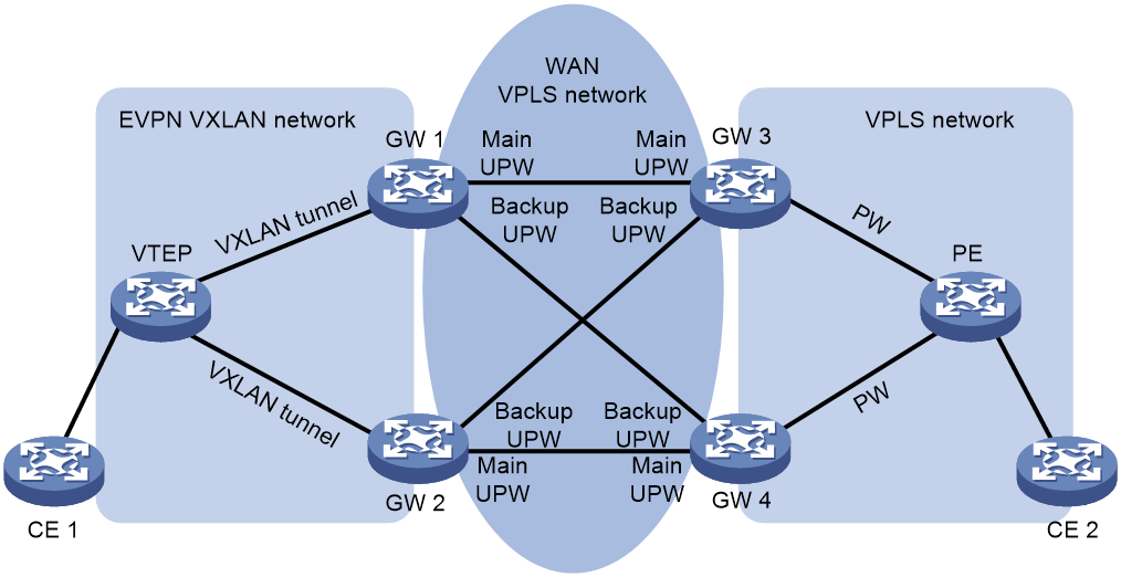
As shown in Figure 18, the VTEP sets up VXLAN tunnels with GW 1 and GW 2, the gateways set up UPWs over the WAN VPLS network as follows:
· GW 1 sets up a main UPW and a backup UPW with GW 3 and GW 4, respectively.
· GW 2 sets up a main UPW and a backup UPW with GW 4 and GW 3, respectively.
When GW 1 or GW 2 receives a packet from a UPW, the gateway performs the following actions:
1. Removes the MPLS encapsulation.
2. Looks up the MAC address table for an outgoing VXLAN tunnel interface.
3. Adds VXLAN encapsulation to the packet.
4. Forwards the packet to the VTEP over the matching VXLAN tunnel.
When receiving a packet from a VXLAN tunnel, GW 1 or GW 2 uses a similar workflow to forward the packet over a UPW to the VPLS network.
Restrictions and guidelines for interconnecting an EVPN VXLAN network with a VPLS network
When the device is operating in standard mode, only the following cards support this feature:
|
Card category |
Cards |
|
CEPC |
CEPC-CQ8L, CEPC-CQ8LA, CEPC-CQ8L1A, CEPC-CQ16L1 |
|
CSPEX |
CSPEX-1802X, CSPEX-1802XA, CSPEX-2612XA, CSPEX-1812X-E, CSPEX-2304X-G, CSPEX-1502XA |
|
SPE |
RX-SPE200-E |
On the redundant gateways at a multihomed EVPN VXLAN network site, configure the same redundancy mode for the UPWs established with the same remote VPLS network site.
To use all-active redundancy mode at a multihomed EVPN VXLAN network site, you must execute the protection dual-receive command on the redundant gateways.
Prerequisites for interconnecting an EVPN VXLAN network with a VPLS network
Before you interconnect an EVPN VXLAN network with a VPLS network, perform the following tasks:
· Configure VPLS and set up LDP PWs or static PWs on the PEs in the VPLS network.
· Configure EVPN VXLAN and set up VXLAN tunnels on the VTEPs in the EVPN VXLAN network.
Mapping an LDP PW to VXLAN tunnels
1. Enter system view.
system-view
2. Enter VSI view.
vsi vsi-name
3. Enter VSI EVPN instance view.
evpn encapsulation vxlan
4. Return to VSI view.
quit
5. Specify LDP signaling for PWs, and enter VSI LDP signaling view.
pwsignaling ldp
By default, no PW signaling protocol is specified for a VSI.
6. Configure an LDP PW for VPLS, and enter VSI LDP PW view.
peer ip-address [ pw-id pw-id ] { dci | no-split-horizon } [ hub | ignore-standby-state | pw-class class-name | tunnel-policy tunnel-policy-name ] *
This LDP PW is used as a UPW for EVPN VXLAN.
If the WAN network connects to three or more data centers, specify the dci keyword to set up a DCI LDP PW to reduce floods between the data centers.
For more information about this command, see VPLS commands in MPLS Command Reference.
7. (Optional.) Assign an ESI to the UPW.
esi esi-id
By default, no ESI is assigned to a PW.
Execute this command on the redundant border devices of an EVPN VXLAN network to which a VPLS network is multihomed.
8. (Optional.) Set the redundancy mode for the UPW.
evpn redundancy-mode { all-active | single-active }
By default, all-active redundancy mode is used.
Execute this command on the redundant border devices of an EVPN VXLAN network to which a VPLS network is multihomed.
9. Create a backup PW for VPLS, and enter VSI LDP backup PW view.
backup-peer ip-address [ pw-id pw-id ] [ pw-class class-name | tunnel-policy tunnel-policy-name ] *
Execute this command on the redundant gateways at a multihomed EVPN VXLAN network site.
For more information about this command, see VPLS commands in MPLS Command Reference.
Mapping a static PW to VXLAN tunnels
1. Enter system view.
system-view
2. Enter VSI view.
vsi vsi-name
3. Enter VSI EVPN instance view.
evpn encapsulation vxlan
4. Return to VSI view.
quit
5. Specify static signaling for PWs, and enter VSI static view.
pwsignaling static
By default, no PW signaling protocol is specified for a VSI.
6. Configure a static PW for VPLS, and enter VSI static PW view.
peer ip-address [ pw-id pw-id ] in-label label-value out-label label-value { dci | no-split-horizon } [ hub | pw-class class-name | tunnel-policy tunnel-policy-name ] *
This static PW is used as a UPW for EVPN VXLAN.
If the WAN network connects to three or more data centers, specify the dci keyword to set up a DCI static PW to reduce floods between the data centers.
For more information about this command, see VPLS commands in MPLS Command Reference.
7. (Optional.) Assign an ESI to the UPW.
esi esi-id
By default, no ESI is assigned to a PW.
Execute this command on the redundant border devices of an EVPN VXLAN network to which a VPLS network is multihomed.
8. (Optional.) Set the redundancy mode for the UPW.
evpn redundancy-mode { all-active | single-active }
By default, all-active redundancy mode is used.
Execute this command on the redundant border devices of an EVPN VXLAN network to which a VPLS network is multihomed.
9. Create a backup PW for VPLS, and enter VSI static backup PW view.
backup-peer ip-address [ pw-id pw-id ] in-label label-value out-label label-value [ pw-class class-name | tunnel-policy tunnel-policy-name ] *
Execute this command on the redundant gateways at a multihomed EVPN VXLAN network site.
For more information about this command, see VPLS commands in MPLS Command Reference.
Interconnecting an EVPN VXLAN network with an EVPN VPLS network
About this task
Perform this task to enable an EVPN VXLAN network to communicate with an EVPN VPLS network.
As shown in Figure 19, for two EVPN VXLAN networks to communicate over an EVPN VPLS network, configure the intermediate border devices GW 1 through GW 4 as follows:
· Configure EVPN VXLAN and EVPN VPLS.
· Interconnect each EVPN VXLAN network with the EVPN VPLS network by configuring route reorigination between the EVPN VXLAN networks and EVPN VPLS network.
Figure 19 Interconnection between an EVPN VXLAN network and an EVPN VPLS network
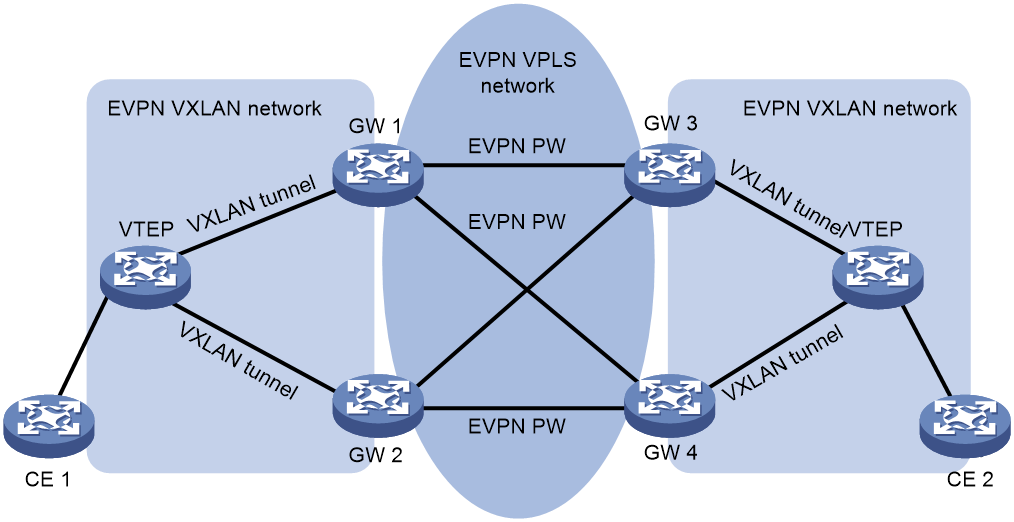
As shown in Figure 19, the gateways reoriginate Ethernet auto-discovery, MAC/IP advertisement, ES, and IMET routes between the EVPN VXLAN networks and EVPN VPLS network. The following uses MAC/IP advertisement routes as an example to introduce how routes are reoriginated:
· After receiving a MAC/IP advertisement route from the attached EVPN VXLAN network, a gateway reoriginates the route as follows:
a. Adds an MPLS label, changes the encapsulation type to MPLS encapsulation, and modifies the RD and route targets for the route.
b. Advertises the reoriginated route to the EVPN VPLS network.
· After receiving a MAC/IP advertisement route from the EVPN VPLS network, a gateway reoriginates the route as follows:
a. Adds a matching VXLAN ID, changes the encapsulation type to VXLAN encapsulation, and modifies the RD and route targets for the route.
b. Advertises the reoriginated route to the attached EVPN VXLAN network.
After learning MAC address entries from MAC/IP advertisement routes, a gateway performs VXLAN or MPLS encapsulation for received packets and forwards them to the EVPN VXLAN networks or EVPN VPLS network based on these entries.
A gateway can be multihomed to the redundant gateways at the same remote site. You must configure the ESI and redundancy mode in VSI view on the redundant gateways.
Restrictions and guidelines
When the device is operating in standard mode, only the following cards support this feature:
|
Card category |
Cards |
|
CEPC |
CEPC-CQ8L, CEPC-CQ8LA, CEPC-CQ8L1A, CEPC-CQ16L1 |
|
CSPEX |
CSPEX-1802X, CSPEX-1802XA, CSPEX-2612XA, CSPEX-1812X-E, CSPEX-2304X-G, CSPEX-1502XA |
|
SPE |
RX-SPE200-E |
On the redundant gateways at a multihomed EVPN VXLAN network site, configure the same redundancy mode for the same VSI.
After you perform this task and bind two EVPN instances using different encapsulation types to a VSI, the device automatically reoriginates Ethernet auto-discovery, ES, and IMET routes for the VSI.
Prerequisites
Before you interconnect an EVPN VXLAN network with an EVPN VPLS network, perform the following tasks:
· Configure EVPN VXLAN and set up VXLAN tunnels on the VTEPs in the EVPN VXLAN network.
· Configure EVPN VPLS and set up EVPN PWs on the PEs in the EVPN VPLS network.
Procedure
1. Enter system view.
system-view
2. Enter VSI view.
vsi vsi-name
3. Bind the VSI to an EVPN instance and specifies the VXLAN encapsulation type.
evpn encapsulation vxlan binding instance instance-name vsi-tag { tag-id | auto-vxlan }
4. Bind the VSI to another EVPN instance and specifies the MPLS encapsulation type.
evpn encapsulation mpls binding instance instance-name vsi-tag tag-id
5. (Optional.) Assign an ESI to the VSI.
esi esi-id
By default, no ESI is assigned to a VSI.
Execute this command on the redundant border devices of an EVPN VXLAN network to which an EVPN VPLS network is multihomed.
6. (Optional.) Set the redundancy mode for the VSI.
evpn redundancy-mode { all-active | single-active }
By default, all-active redundancy mode is used.
Execute this command on the redundant border devices of an EVPN VXLAN network to which an EVPN VPLS network is multihomed.
7. Return to system view.
quit
8. Enter BGP instance view.
bgp as-number [ instance instance-name ]
9. Enable reorigination of MAC/IP advertisement routes.
evpn mac re-originated enable
By default, reorigination of MAC/IP advertisement routes is disabled.
10. Enter BGP EVPN address family view.
address-family l2vpn evpn
11. Enable the device to reoriginate MAC/IP advertisement routes based on those received from a peer or peer group.
peer { group-name | ipv4-address [ mask-length ] | ipv6-address [ prefix-length ] } re-originated mac [ replace-rt ]
By default, the device does not reoriginate MAC/IP advertisement routes based on those received from peers or peer groups.
12. (Optional.) Suppress advertisement of original BGP EVPN routes to a peer or peer group and withdraw advertised original BGP EVPN routes.
peer { group-name | ipv4-address [ mask-length ] | ipv6-address [ prefix-length ] } suppress original-route { auto-discovery | es | imet }
By default, the device advertises original BGP EVPN routes to peers and peer groups.
Enabling packet statistics for VXLAN tunnels
About this task
Perform this task to enable packet statistics globally for automatically created VXLAN tunnels or VXLAN tunnels associated with L3 VXLAN IDs.
If you enable packet statistics for automatically created VXLAN tunnels, follow these guidelines:
· To display the packet statistics for VXLAN tunnels, use the display interface tunnel command in any view.
· To clear the packet statistics for VXLAN tunnels, use the reset counters interface tunnel command in user view.
If you enable packet statistics for VXLAN tunnels associated with L3 VXLAN IDs, follow these guidelines:
· To display the packet statistics for VXLAN tunnels, use the display vxlan tunnel command in any view.
· To clear the packet statistics for VXLAN tunnels, use the reset l2vpn statistics tunnel command in user view.
Procedure
1. Enter system view.
system-view
2. Enable packet statistics for VXLAN tunnels.
tunnel statistics vxlan { auto | l3-vni }
By default, the packet statistics feature is disabled for VXLAN tunnels.
For more information about this command, see VXLAN Command Reference.
Enabling SNMP notifications for EVPN
About this task
If SNMP notifications are enabled for EVPN, a MAC mobility suppression notification is sent to SNMP module after the MAC mobility suppression threshold is reached. For SNMP notifications to be sent correctly, you must also configure SNMP on the device. For more information about SNMP configuration, see Network Management and Monitoring Configuration Guide.
Procedure
1. Enter system view.
system-view
2. Enable SNMP notifications for EVPN.
snmp-agent trap enable evpn [ mac-mobility-suppression ]
By default, SNMP notifications are disabled for EVPN.
Display and maintenance commands for EVPN VXLAN
Execute display commands in any view and reset commands in user view.
|
Task |
Command |
|
Display BGP peer group information. |
display bgp [ instance instance-name ] group l2vpn evpn [ group-name group-name ] |
|
Display BGP EVPN routes. |
display bgp [ instance instance-name ] l2vpn evpn [ peer { ipv4-address | ipv6-address } { advertised-routes | received-routes } [ { evpn-route route-length | evpn-prefix } [ verbose ] | statistics ] | [ route-distinguisher route-distinguisher | route-type { auto-discovery | es | igmp-js | igmp-ls | imet | ip-prefix | mac-ip | smet } ] * [ { evpn-route route-length | evpn-prefix } [ advertise-info ] | ipv4-address | ipv6-address | mac-address ] | statistics ] |
|
Display BGP peer or peer group information. |
display bgp [ instance instance-name ] peer l2vpn evpn [ ipv4-address mask-length | ipv6-address prefix-length | { ipv4-address | ipv6-address | group-name group-name } log-info | [ ipv4-address | ipv6-address ] verbose ] display bgp [ instance instance-name ] l2vpn evpn [ peer { ipv4-address | ipv6-address } { accepted-routes | not-accepted-routes } ] |
|
Display information about BGP update groups. |
display bgp [ instance instance-name ] update-group l2vpn evpn [ ipv4-address | ipv6-address ] |
|
Display dampened BGP EVPN routes. |
display bgp [ instance instance-name ] l2vpn evpn dampened |
|
Display BGP EVPN route dampening parameters. |
display bgp [ instance instance-name ] dampening parameter l2vpn evpn |
|
Display flapping statistics about BGP EVPN routes. |
display bgp [ instance instance-name ] l2vpn evpn flap-info |
|
Display the route targets sourced from the EVPN process and ES-import route targets for BGP. |
display bgp [ instance instance-name ] route-target evpn |
|
Display the route targets sourced from VPN instances for BGP. |
display bgp [ instance instance-name ] route-target l3vpn [ ipv4 | ipv6 | evpn ] [ vpn-instance vpn-instance-name ] |
|
Display information about IPv4 peers that are automatically discovered through BGP. |
display evpn auto-discovery { { imet | mac-ip } [ mpls | vxlan ] [ peer ip-address ] [ vsi vsi-name ] | macip-prefix [ nexthop next-hop ] [ count ] } |
|
Display EVPN ES information. |
display evpn es { local [ count | [ vsi vsi-name ] [ esi esi-id ] [ verbose ] ] | remote [ vsi vsi-name ] [ esi esi-id ] [ nexthop next-hop ] [ verbose ] } |
|
Display information about IPv6 peers that are automatically discovered through BGP. |
display evpn ipv6 auto-discovery { { imet | mac-ip } [ vxlan ] [ peer ipv6-address ] [ vsi vsi-name ] | macip-prefix [ nexthop next-hop ] [ count ] } |
|
Display EVPN ARP entries. |
display evpn route arp [ local | remote ] [ public-instance | vpn-instance vpn-instance-name ] [ ip ip-address ] [ count ] |
|
Display ARP flood suppression entries. |
display evpn route arp suppression [ vxlan ] [ ip ip-address ] [ local | remote ] [ vsi vsi-name ] [ count ] |
|
Display EVPN ARP mobility information. |
display evpn route arp-mobility [ public-instance | vpn-instance vpn-instance-name ] [ ip ip-address ] [ verbose ] |
|
Display EVPN MAC address entries. |
display evpn route mac [ mac-address mac-address | umr [ verbose ] ] [ mpls | vxlan ] [ local | remote ] [ vsi vsi-name ] [ count ] |
|
Display EVPN MAC mobility information. |
display evpn route mac-mobility [ evpn-instance instance-name | interface interface-type interface-number | vsi vsi-name ] [ mac-address mac-address ] [ verbose ] |
|
Display EVPN ND entries. |
display evpn route nd [ local | remote ] [ public-instance | vpn-instance vpn-instance-name ] [ ipv6 ipv6-address ] [ count ] |
|
Display ND flood suppression entries. |
display evpn route nd suppression [ local | remote ] [ ipv6 ipv6-address ] [ vsi vsi-name ] [ count ] |
|
Display EVPN ND mobility information. |
display evpn route nd-mobility [ public-instance | vpn-instance vpn-instance-name ] [ ipv6 ipv6-address ] |
|
Display the routing table for a VPN instance. |
display evpn routing-table [ ipv6 ] { public-instance | vpn-instance vpn-instance-name } [ count ] |
|
Display EVPN instance information. |
display evpn instance [ name instance-name | vsi vsi-name ] |
|
Display site-facing interfaces excluded from traffic forwarding by split horizon. |
In standalone mode: display l2vpn forwarding evpn split-horizon { ac interface interface-type interface-number | ac interface interface-type interface-number service-instance instance-id | tunnel tunnel-number } slot slot-number [ cpu cpu-number ] In IRF mode: display l2vpn forwarding evpn split-horizon { ac interface interface-type interface-number | ac interface interface-type interface-number service-instance instance-id | tunnel tunnel-number } chassis chassis-number slot slot-number [ cpu cpu-number ] |
|
Reset BGP EVPN route dampening information and disable BGP EVPN route dampening. |
reset bgp [ instance instance-name ] dampening l2vpn evpn |
|
Reset flapping statistics about BGP EVPN routes. |
reset bgp [ instance instance-name ] flap-info l2vpn evpn [ as-path-acl { as-path-acl-number | as-path-acl-name } | peer [ ipv4-address [ mask-length ] | peer ipv6-address [ prefix-length ] ] ] |
|
Advertise ARP information for suppressed IP addresses for one time. |
reset evpn route arp-mobility suppression [ public-instance | vpn-instance vpn-instance-name [ ip ip-address ] ] |
|
Advertise suppressed MAC addresses for one time. |
reset evpn route mac-mobility suppression [ evpn-instance instance-name | interface interface-type interface-number | vsi vsi-name ] [ mac mac-address ] |
|
Advertise ARP information for suppressed IPv6 addresses for one time. |
reset evpn route nd-mobility suppression [ public-instance | vpn-instance vpn-instance-name [ ipv6 ipv6-address ] ] |
|
|
NOTE: For more information about the display bgp group, display bgp peer, and display bgp update-group commands, see BGP commands in Layer 3—IP Routing Command Reference. For more information about the display bgp route-target l3vpn command, see MPLS L3VPN commands in MPLS Command Reference. |
EVPN VXLAN configuration examples
Example: Configuring a centralized IPv4 EVPN gateway
Network configuration
As shown in Figure 20:
· Configure VXLAN 10 and VXLAN 20 on Router A, Router B, and Router C to provide connectivity for the VMs in the VXLANs across the network sites.
· Configure Router C as a centralized EVPN gateway to provide gateway services and access to the connected Layer 3 network.
· Configure Router D as an RR to reflect BGP EVPN routes between Router A, Router B, and Router C.
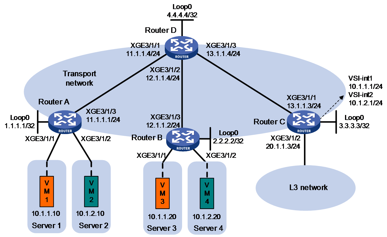
Procedure
1. On VM 1 and VM 3, specify 10.1.1.1 as the gateway address. On VM 2 and VM 4, specify 10.1.2.1 as the gateway address. (Details not shown.)
2. Configure IP addresses and unicast routing settings:
# Assign IP addresses to interfaces, as shown in Figure 20. (Details not shown.)
# Configure OSPF on all transport network routers (Routers A through D) for them to reach one another. (Details not shown.)
3. Configure Router A:
# Enable L2VPN.
<RouterA> system-view
[RouterA] l2vpn enable
# Disable remote MAC address learning and remote ARP learning.
[RouterA] vxlan tunnel mac-learning disable
[RouterA] vxlan tunnel arp-learning disable
# Create an EVPN instance on VSI vpna, and configure the router to automatically generate an RD and a route target for the EVPN instance.
[RouterA] vsi vpna
[RouterA-vsi-vpna] arp suppression enable
[RouterA-vsi-vpna] evpn encapsulation vxlan
[RouterA-vsi-vpna-evpn-vxlan] route-distinguisher auto
[RouterA-vsi-vpna-evpn-vxlan] vpn-target auto
[RouterA-vsi-vpna-evpn-vxlan] quit
# Create VXLAN 10.
[RouterA-vsi-vpna] vxlan 10
[RouterA-vsi-vpna-vxlan-10] quit
[RouterA-vsi-vpna] quit
# Create an EVPN instance on VSI vpnb, and configure the router to automatically generate an RD and a route target for the EVPN instance.
[RouterA] vsi vpnb
[RouterA-vsi-vpnb] arp suppression enable
[RouterA-vsi-vpnb] evpn encapsulation vxlan
[RouterA-vsi-vpnb-evpn-vxlan] route-distinguisher auto
[RouterA-vsi-vpnb-evpn-vxlan] vpn-target auto
[RouterA-vsi-vpnb-evpn-vxlan] quit
# Create VXLAN 20.
[RouterA-vsi-vpnb] vxlan 20
[RouterA-vsi-vpnb-vxlan-20] quit
[RouterA-vsi-vpnb] quit
# Configure BGP to advertise BGP EVPN routes.
[RouterA] bgp 200
[RouterA-bgp-default] peer 4.4.4.4 as-number 200
[RouterA-bgp-default] peer 4.4.4.4 connect-interface loopback 0
[RouterA-bgp-default] address-family l2vpn evpn
[RouterA-bgp-default-evpn] peer 4.4.4.4 enable
[RouterA-bgp-default-evpn] quit
[RouterA-bgp-default] quit
# Map Ten-GigabitEthernet 3/1/1 to VSI vpna.
[RouterA] interface ten-gigabitethernet 3/1/1
[RouterA-Ten-GigabitEthernet3/1/1] xconnect vsi vpna
[RouterA-Ten-GigabitEthernet3/1/1] quit
# Map Ten-GigabitEthernet 3/1/2 to VSI vpnb.
[RouterA] interface ten-gigabitethernet 3/1/2
[RouterA-Ten-GigabitEthernet3/1/2] xconnect vsi vpnb
[RouterA-Ten-GigabitEthernet3/1/2] quit
4. Configure Router B:
# Enable L2VPN.
<RouterB> system-view
[RouterB] l2vpn enable
# Disable remote MAC address learning and remote ARP learning.
[RouterB] vxlan tunnel mac-learning disable
[RouterB] vxlan tunnel arp-learning disable
# Create an EVPN instance on VSI vpna, and configure the router to automatically generate an RD and a route target for the EVPN instance.
[RouterB] vsi vpna
[RouterB-vsi-vpna] arp suppression enable
[RouterB-vsi-vpna] evpn encapsulation vxlan
[RouterB-vsi-vpna-evpn-vxlan] route-distinguisher auto
[RouterB-vsi-vpna-evpn-vxlan] vpn-target auto
[RouterB-vsi-vpna-evpn-vxlan] quit
# Create VXLAN 10.
[RouterB-vsi-vpna] vxlan 10
[RouterB-vsi-vpna-vxlan-10] quit
[RouterB-vsi-vpna] quit
# Create an EVPN instance on VSI vpnb, and configure the router to automatically generate an RD and a route target for the EVPN instance.
[RouterB] vsi vpnb
[RouterB-vsi-vpnb] arp suppression enable
[RouterB-vsi-vpnb] evpn encapsulation vxlan
[RouterB-vsi-vpnb-evpn-vxlan] route-distinguisher auto
[RouterB-vsi-vpnb-evpn-vxlan] vpn-target auto
[RouterB-vsi-vpnb-evpn-vxlan] quit
# Create VXLAN 20.
[RouterB-vsi-vpnb] vxlan 20
[RouterB-vsi-vpnb-vxlan-20] quit
[RouterB-vsi-vpnb] quit
# Configure BGP to advertise BGP EVPN routes.
[RouterB] bgp 200
[RouterB-bgp-default] peer 4.4.4.4 as-number 200
[RouterB-bgp-default] peer 4.4.4.4 connect-interface loopback 0
[RouterB-bgp-default] address-family l2vpn evpn
[RouterB-bgp-default-evpn] peer 4.4.4.4 enable
[RouterB-bgp-default-evpn] quit
[RouterB-bgp-default] quit
# Map Ten-GigabitEthernet 3/1/1 to VSI vpna.
[RouterB] interface ten-gigabitethernet 3/1/1
[RouterB-Ten-GigabitEthernet3/1/1] xconnect vsi vpna
[RouterB-Ten-GigabitEthernet3/1/1] quit
# Map Ten-GigabitEthernet 3/1/2 to VSI vpnb.
[RouterB] interface ten-gigabitethernet 3/1/2
[RouterB-Ten-GigabitEthernet3/1/2] xconnect vsi vpnb
[RouterB-Ten-GigabitEthernet3/1/2] quit
5. Configure Router C:
# Enable L2VPN.
<RouterC> system-view
[RouterC] l2vpn enable
# Disable remote MAC address learning and remote ARP learning.
[RouterC] vxlan tunnel mac-learning disable
[RouterC] vxlan tunnel arp-learning disable
# Create an EVPN instance on VSI vpna, and configure the router to automatically generate an RD and a route target for the EVPN instance.
[RouterC] vsi vpna
[RouterC-vsi-vpna] arp suppression enable
[RouterC-vsi-vpna] evpn encapsulation vxlan
[RouterC-vsi-vpna-evpn-vxlan] route-distinguisher auto
[RouterC-vsi-vpna-evpn-vxlan] vpn-target auto
[RouterC-vsi-vpna-evpn-vxlan] quit
# Create VXLAN 10.
[RouterC-vsi-vpna] vxlan 10
[RouterC-vsi-vpna-vxlan-10] quit
[RouterC-vsi-vpna] quit
# Create an EVPN instance on VSI vpnb, and configure the router to automatically generate an RD and a route target for the EVPN instance.
[RouterC] vsi vpnb
[RouterC-vsi-vpnb] evpn encapsulation vxlan
[RouterC-vsi-vpnb-evpn-vxlan] route-distinguisher auto
[RouterC-vsi-vpnb-evpn-vxlan] vpn-target auto
[RouterC-vsi-vpnb-evpn-vxlan] quit
# Create VXLAN 20.
[RouterC-vsi-vpnb] vxlan 20
[RouterC-vsi-vpnb-vxlan-20] quit
[RouterC-vsi-vpnb] quit
# Configure BGP to advertise BGP EVPN routes.
[RouterC] bgp 200
[RouterC-bgp-default] peer 4.4.4.4 as-number 200
[RouterC-bgp-default] peer 4.4.4.4 connect-interface loopback 0
[RouterC-bgp-default] address-family l2vpn evpn
[RouterC-bgp-default-evpn] peer 4.4.4.4 enable
[RouterC-bgp-default-evpn] quit
[RouterC-bgp-default] quit
# Create VSI-interface 1 and assign the interface an IP address. The IP address will be used as the gateway address for VXLAN 10.
[RouterC] interface vsi-interface 1
[RouterC-Vsi-interface1] ip address 10.1.1.1 255.255.255.0
[RouterC-Vsi-interface1] quit
# Specify VSI-interface 1 as the gateway interface for VSI vpna.
[RouterC] vsi vpna
[RouterC-vsi-vpna] gateway vsi-interface 1
[RouterC-vsi-vpna] quit
# Create VSI-interface 2 and assign the interface an IP address. The IP address will be used as the gateway address for VXLAN 20.
[RouterC] interface vsi-interface 2
[RouterC-Vsi-interface2] ip address 10.1.2.1 255.255.255.0
[RouterC-Vsi-interface2] quit
# Specify VSI-interface 2 as the gateway interface for VSI vpnb.
[RouterC] vsi vpnb
[RouterC-vsi-vpnb] gateway vsi-interface 2
[RouterC-vsi-vpnb] quit
6. Configure Router D:
# Establish BGP connections with other transport network routers.
<RouterD> system-view
[RouterD] bgp 200
[RouterD-bgp-default] group evpn
[RouterD-bgp-default] peer 1.1.1.1 group evpn
[RouterD-bgp-default] peer 2.2.2.2 group evpn
[RouterD-bgp-default] peer 3.3.3.3 group evpn
[RouterD-bgp-default] peer evpn as-number 200
[RouterD-bgp-default] peer evpn connect-interface loopback 0
# Configure BGP to advertise BGP EVPN routes, and disable route target filtering for BGP EVPN routes.
[RouterD-bgp-default] address-family l2vpn evpn
[RouterD-bgp-default-evpn] peer evpn enable
[RouterD-bgp-default-evpn] undo policy vpn-target
# Configure Router D as an RR.
[RouterD-bgp-default-evpn] peer evpn reflect-client
[RouterD-bgp-default-evpn] quit
[RouterD-bgp-default] quit
Verifying the configuration
1. Verify the EVPN gateway settings on Router C:
# Verify that Router C has advertised MAC/IP advertisement routes and IMET routes for the gateways and received MAC/IP advertisement routes and IMET routes from Router A and Router B. (Details not shown.)
# Verify that the VXLAN tunnel interfaces are up on Router C.
[RouterC] display interface tunnel
Tunnel0
Interface index: 261
Current state: UP
Line protocol state: UP
Description: Tunnel0 Interface
Bandwidth: 64 kbps
Maximum transmission unit: 1464
Internet protocol processing: Disabled
Last clearing of counters: Never
Tunnel source 3.3.3.3, destination 2.2.2.2
Tunnel protocol/transport UDP_VXLAN/IP
Last 300 seconds input rate: 0 bytes/sec, 0 bits/sec, 0 packets/sec
Last 300 seconds output rate: 0 bytes/sec, 0 bits/sec, 0 packets/sec
Input: 0 packets, 0 bytes, 0 drops
Output: 0 packets, 0 bytes, 0 drops
Tunnel1
Interface index: 262
Current state: UP
Line protocol state: UP
Description: Tunnel1 Interface
Bandwidth: 64 kbps
Maximum transmission unit: 1464
Internet protocol processing: Disabled
Last clearing of counters: Never
Tunnel source 3.3.3.3, destination 1.1.1.1
Tunnel protocol/transport UDP_VXLAN/IP
Last 300 seconds input rate: 0 bytes/sec, 0 bits/sec, 0 packets/sec
Last 300 seconds output rate: 0 bytes/sec, 0 bits/sec, 0 packets/sec
Input: 277 packets, 20306 bytes, 0 drops
Output: 1099 packets, 0 bytes, 0 drops
# Verify that the VSI interfaces are up on Router C.
[RouterC] display interface vsi-interface
Vsi-interface1
Interface index: 263
Current state: UP
Line protocol state: UP
Description: Vsi-interface1 Interface
Bandwidth: 1000000 kbps
Maximum transmission unit: 1500
Internet address: 10.1.1.1/24 (primary)
IP packet frame type: Ethernet II, hardware address: 0003-0003-0003
IPv6 packet frame type: Ethernet II, hardware address: 0003-0003-0003
Physical: Unknown, baudrate: 1000000 kbps
Last clearing of counters: Never
Last 300 seconds input rate: 0 bytes/sec, 0 bits/sec, 0 packets/sec
Last 300 seconds output rate: 0 bytes/sec, 0 bits/sec, 0 packets/sec
Input: 0 packets, 0 bytes, 0 drops
Output: 0 packets, 0 bytes, 0 drops
Vsi-interface2
Interface index: 264
Current state: UP
Line protocol state: UP
Description: Vsi-interface2 Interface
Bandwidth: 1000000 kbps
Maximum transmission unit: 1500
Internet address: 10.1.2.1/24 (primary)
IP packet frame type: Ethernet II, hardware address: 0003-0003-0003
IPv6 packet frame type: Ethernet II, hardware address: 0003-0003-0003
Physical: Unknown, baudrate: 1000000 kbps
Last clearing of counters: Never
Last 300 seconds input rate: 0 bytes/sec, 0 bits/sec, 0 packets/sec
Last 300 seconds output rate: 0 bytes/sec, 0 bits/sec, 0 packets/sec
Input: 0 packets, 0 bytes, 0 drops
Output: 0 packets, 0 bytes, 0 drops
# Verify that the VXLAN tunnels have been assigned to the VXLANs, and the VSI interfaces are the gateway interfaces of their respective VXLANs.
[RouterC] display l2vpn vsi verbose
VSI Name: vpna
VSI Index : 0
VSI State : Up
MTU : 1500
Diffserv Mode : -
Bandwidth : Unlimited
Broadcast Restrain : 5120 kbps
Multicast Restrain : 5120 kbps
Unknown Unicast Restrain: 5120 kbps
MAC Learning : Enabled
MAC Table Limit : Unlimited
MAC Learning rate : -
Local MAC aging time : 300 sec
Remote MAC aging time : 300 sec
Drop Unknown : Disabled
PW Redundancy Mode : Slave
DSCP : -
Service Class : -
Flooding : Enabled
ESI : 0000.0000.0000.0000.0000
Redundancy Mode : All-active
Straight-fwd PW-to-AC : Disabled
Statistics : Disabled
Gateway Interface : VSI-interface 1
VXLAN ID : 10
Tunnel Statistics : Disabled
Tunnels:
Tunnel Name Link ID State Type Flood Proxy
Tunnel0 0x5000000 UP Auto Disabled
Tunnel1 0x5000001 UP Auto Disabled
…
VSI Name: vpnb
VSI Index : 1
VSI State : Up
MTU : 1500
Diffserv Mode : -
Bandwidth : Unlimited
Broadcast Restrain : 5120 kbps
Multicast Restrain : 5120 kbps
Unknown Unicast Restrain: 5120 kbps
MAC Learning : Enabled
MAC Table Limit : Unlimited
MAC Learning rate : -
Local MAC aging time : 300 sec
Remote MAC aging time : 300 sec
Drop Unknown : Disabled
DSCP : -
Service Class : -
Flooding : Enabled
ESI : 0000.0000.0000.0000.0000
Redundancy Mode : All-active
Straight-fwd PW-to-AC : Disabled
Statistics : Disabled
Gateway Interface : VSI-interface 2
VXLAN ID : 20
Tunnel Statistics : Disabled
Tunnels:
Tunnel Name Link ID State Type Flood Proxy
Tunnel0 0x5000000 UP Auto Disabled
Tunnel1 0x5000001 UP Auto Disabled
# Verify that Router C has created EVPN ARP entries for the VMs.
[RouterC] display evpn route arp
Flags: D - Dynamic B - BGP L - Local active
G - Gateway S - Static M - Mapping I - Invalid
Public instance Interface: Vsi-interface1
IP address MAC address Router MAC VSI index Flags
10.1.1.1 0003-0003-0003 - 0 GL
10.1.1.10 0000-1234-0001 - 0 B
10.1.1.20 0000-1234-0003 - 0 B
Public instance Interface: Vsi-interface2
IP address MAC address Router MAC VSI index Flags
10.1.2.1 0005-0005-0005 - 1 GL
10.1.2.10 0000-1234-0002 - 1 B
10.1.2.20 0000-1234-0004 - 1 B
# Verify that Router C has created FIB entries for the VMs.
[RouterC] display fib 10.1.1.10
Destination count: 1 FIB entry count: 1
Flag:
U:Usable G:Gateway H:Host B:Blackhole D:Dynamic S:Static
R:Relay F:FRR
Destination/Mask Nexthop Flag OutInterface/Token Label
10.1.1.10/32 10.1.1.10 UH Vsi1 Null
2. Verify that VM 1, VM 2, VM 3, and VM 4 can communicate with one another. (Details not shown.)
Example: Configuring distributed IPv4 EVPN gateways in symmetric IRB mode
Network configuration
As shown in Figure 21:
· Configure VXLAN 10 and VXLAN 20 on Router A and Router B to provide connectivity for the VMs in the VXLANs across the network sites.
· Configure Router A and Router B as distributed EVPN gateways to provide gateway services in symmetric IRB mode. Configure Router C as a border gateway to provide access to the connected Layer 3 network.
· Configure Router D as an RR to reflect BGP EVPN routes between Router A, Router B, and Router C.
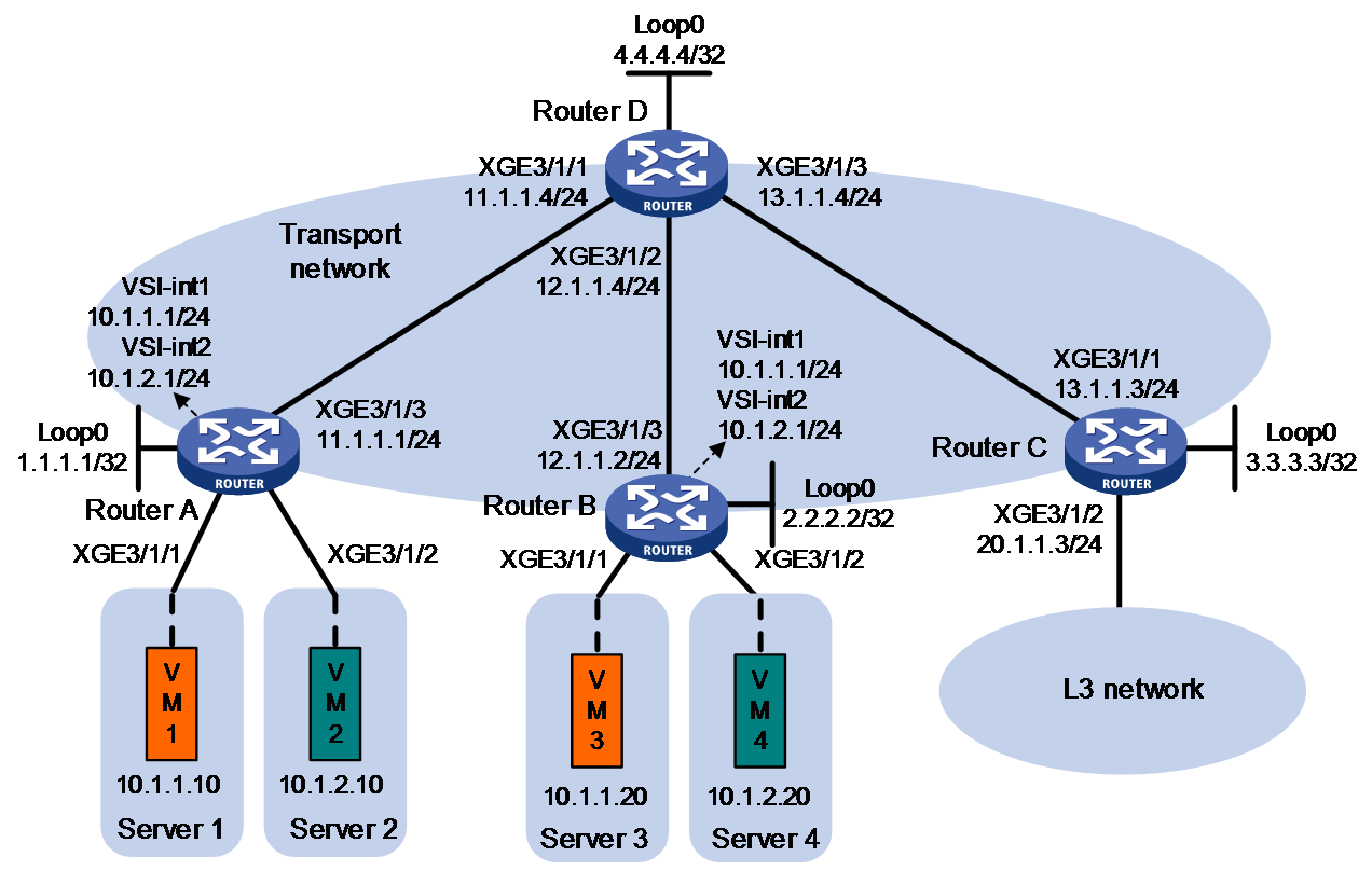
Procedure
1. On VM 1 and VM 3, specify 10.1.1.1 as the gateway address. On VM 2 and VM 4, specify 10.1.2.1 as the gateway address. (Details not shown.)
2. Configure IP addresses and unicast routing settings:
# Assign IP addresses to interfaces, as shown in Figure 21. (Details not shown.)
# Configure OSPF on all transport network routers (Routers A through D) for them to reach one another. (Details not shown.)
3. Configure Router A:
# Enable L2VPN.
<RouterA> system-view
[RouterA] l2vpn enable
# Disable remote MAC address learning and remote ARP learning.
[RouterA] vxlan tunnel mac-learning disable
[RouterA] vxlan tunnel arp-learning disable
# Create an EVPN instance on VSI vpna, and configure the router to automatically generate an RD and a route target for the EVPN instance.
[RouterA] vsi vpna
[RouterA-vsi-vpna] evpn encapsulation vxlan
[RouterA-vsi-vpna-evpn-vxlan] route-distinguisher auto
[RouterA-vsi-vpna-evpn-vxlan] vpn-target auto
[RouterA-vsi-vpna-evpn-vxlan] quit
# Create VXLAN 10.
[RouterA-vsi-vpna] vxlan 10
[RouterA-vsi-vpna-vxlan-10] quit
[RouterA-vsi-vpna] quit
# Create an EVPN instance on VSI vpnb, and configure the router to automatically generate an RD and a route target for the EVPN instance.
[RouterA] vsi vpnb
[RouterA-vsi-vpnb] evpn encapsulation vxlan
[RouterA-vsi-vpnb-evpn-vxlan] route-distinguisher auto
[RouterA-vsi-vpnb-evpn-vxlan] vpn-target auto
[RouterA-vsi-vpnb-evpn-vxlan] quit
# Create VXLAN 20.
[RouterA-vsi-vpnb] vxlan 20
[RouterA-vsi-vpnb-vxlan-20] quit
[RouterA-vsi-vpnb] quit
# Configure BGP to advertise BGP EVPN routes.
[RouterA] bgp 200
[RouterA-bgp-default] peer 4.4.4.4 as-number 200
[RouterA-bgp-default] peer 4.4.4.4 connect-interface loopback 0
[RouterA-bgp-default] address-family l2vpn evpn
[RouterA-bgp-default-evpn] peer 4.4.4.4 enable
[RouterA-bgp-default-evpn] quit
[RouterA-bgp-default] quit
# Map Ten-GigabitEthernet 3/1/1 to VSI vpna.
[RouterA] interface ten-gigabitethernet 3/1/1
[RouterA-Ten-GigabitEthernet3/1/1] xconnect vsi vpna
[RouterA-Ten-GigabitEthernet3/1/1] quit
# Map Ten-GigabitEthernet 3/1/2 to VSI vpnb.
[RouterA] interface ten-gigabitethernet 3/1/2
[RouterA-Ten-GigabitEthernet3/1/2] xconnect vsi vpnb
[RouterA-Ten-GigabitEthernet3/1/2] quit
# Configure RD and route target settings for VPN instance l3vpna.
[RouterA] ip vpn-instance l3vpna
[RouterA-vpn-instance-l3vpna] route-distinguisher 1:1
[RouterA-vpn-instance-l3vpna] address-family ipv4
[RouterA-vpn-ipv4-l3vpna] vpn-target 2:2
[RouterA-vpn-ipv4-l3vpna] quit
[RouterA-vpn-instance-l3vpna] address-family evpn
[RouterA-vpn-evpn-l3vpna] vpn-target 1:1
[RouterA-vpn-evpn-l3vpna] quit
[RouterA-vpn-instance-l3vpna] quit
# Configure VSI-interface 1.
[RouterA] interface vsi-interface 1
[RouterA-Vsi-interface1] ip binding vpn-instance l3vpna
[RouterA-Vsi-interface1] ip address 10.1.1.1 255.255.255.0
[RouterA-Vsi-interface1] mac-address 1-1-1
[RouterA-Vsi-interface1] distributed-gateway local
[RouterA-Vsi-interface1] local-proxy-arp enable
[RouterA-Vsi-interface1] quit
# Configure VSI-interface 2.
[RouterA] interface vsi-interface 2
[RouterA-Vsi-interface2] ip binding vpn-instance l3vpna
[RouterA-Vsi-interface2] ip address 10.1.2.1 255.255.255.0
[RouterA-Vsi-interface2] mac-address 2-2-2
[RouterA-Vsi-interface2] distributed-gateway local
[RouterA-Vsi-interface2] local-proxy-arp enable
[RouterA-Vsi-interface2] quit
# Associate VSI-interface 3 with VPN instance l3vpna, and configure the L3 VXLAN ID as 1000 for the VPN instance.
[RouterA] interface vsi-interface 3
[RouterA-Vsi-interface3] ip binding vpn-instance l3vpna
[RouterA-Vsi-interface3] l3-vni 1000
[RouterA-Vsi-interface3] quit
# Specify VSI-interface 1 as the gateway interface for VSI vpna.
[RouterA] vsi vpna
[RouterA-vsi-vpna] gateway vsi-interface 1
[RouterA-vsi-vpna] quit
# Specify VSI-interface 2 as the gateway interface for VSI vpnb.
[RouterA] vsi vpnb
[RouterA-vsi-vpnb] gateway vsi-interface 2
[RouterA-vsi-vpnb] quit
4. Configure Router B:
# Enable L2VPN.
<RouterB> system-view
[RouterB] l2vpn enable
# Disable remote MAC address learning and remote ARP learning.
[RouterB] vxlan tunnel mac-learning disable
[RouterB] vxlan tunnel arp-learning disable
# Create an EVPN instance on VSI vpna, and configure the router to automatically generate an RD and a route target for the EVPN instance.
[RouterB] vsi vpna
[RouterB-vsi-vpna] evpn encapsulation vxlan
[RouterB-vsi-vpna-evpn-vxlan] route-distinguisher auto
[RouterB-vsi-vpna-evpn-vxlan] vpn-target auto
[RouterB-vsi-vpna-evpn-vxlan] quit
# Create VXLAN 10.
[RouterB-vsi-vpna] vxlan 10
[RouterB-vsi-vpna-vxlan-10] quit
[RouterB-vsi-vpna] quit
# Create an EVPN instance on VSI vpnb, and configure the router to automatically generate an RD and a route target for the EVPN instance.
[RouterB] vsi vpnb
[RouterB-vsi-vpnb] evpn encapsulation vxlan
[RouterB-vsi-vpnb-evpn-vxlan] route-distinguisher auto
[RouterB-vsi-vpnb-evpn-vxlan] vpn-target auto
[RouterB-vsi-vpnb-evpn-vxlan] quit
# Create VXLAN 20.
[RouterB-vsi-vpnb] vxlan 20
[RouterB-vsi-vpnb-vxlan-20] quit
[RouterB-vsi-vpnb] quit
# Configure BGP to advertise BGP EVPN routes.
[RouterB] bgp 200
[RouterB-bgp-default] peer 4.4.4.4 as-number 200
[RouterB-bgp-default] peer 4.4.4.4 connect-interface loopback 0
[RouterB-bgp-default] address-family l2vpn evpn
[RouterB-bgp-default-evpn] peer 4.4.4.4 enable
[RouterB-bgp-default-evpn] quit
[RouterB-bgp-default] quit
# Map Ten-GigabitEthernet 3/1/1 to VSI vpna.
[RouterB] interface ten-gigabitethernet 3/1/1
[RouterB-Ten-GigabitEthernet3/1/1] xconnect vsi vpna
[RouterB-Ten-GigabitEthernet3/1/1] quit
# Map Ten-GigabitEthernet 3/1/2 to VSI vpnb.
[RouterB] interface ten-gigabitethernet 3/1/2
[RouterB-Ten-GigabitEthernet3/1/2] xconnect vsi vpnb
[RouterB-Ten-GigabitEthernet3/1/2] quit
# Configure RD and route target settings for VPN instance l3vpna.
[RouterB] ip vpn-instance l3vpna
[RouterB-vpn-instance-l3vpna] route-distinguisher 1:1
[RouterB-vpn-instance-l3vpna] address-family ipv4
[RouterB-vpn-ipv4-l3vpna] vpn-target 2:2
[RouterB-vpn-ipv4-l3vpna] quit
[RouterB-vpn-instance-l3vpna] address-family evpn
[RouterB-vpn-evpn-l3vpna] vpn-target 1:1
[RouterB-vpn-evpn-l3vpna] quit
[RouterB-vpn-instance-l3vpna] quit
# Configure VSI-interface 1.
[RouterB] interface vsi-interface 1
[RouterB-Vsi-interface1] ip binding vpn-instance l3vpna
[RouterB-Vsi-interface1] ip address 10.1.1.1 255.255.255.0
[RouterB-Vsi-interface1] mac-address 1-1-1
[RouterB-Vsi-interface1] distributed-gateway local
[RouterB-Vsi-interface1] local-proxy-arp enable
[RouterB-Vsi-interface1] quit
# Configure VSI-interface 2.
[RouterB] interface vsi-interface 2
[RouterB-Vsi-interface2] ip binding vpn-instance l3vpna
[RouterB-Vsi-interface2] ip address 10.1.2.1 255.255.255.0
[RouterB-Vsi-interface2] mac-address 2-2-2
[RouterB-Vsi-interface2] distributed-gateway local
[RouterB-Vsi-interface2] local-proxy-arp enable
[RouterB-Vsi-interface2] quit
# Associate VSI-interface 3 with VPN instance l3vpna, and configure the L3 VXLAN ID as 1000 for the VPN instance.
[RouterB] interface vsi-interface 3
[RouterB-Vsi-interface3] ip binding vpn-instance l3vpna
[RouterB-Vsi-interface3] l3-vni 1000
[RouterB-Vsi-interface3] quit
# Specify VSI-interface 1 as the gateway interface for VSI vpna.
[RouterB] vsi vpna
[RouterB-vsi-vpna] gateway vsi-interface 1
[RouterB-vsi-vpna] quit
# Specify VSI-interface 2 as the gateway interface for VSI vpnb.
[RouterB] vsi vpnb
[RouterB-vsi-vpnb] gateway vsi-interface 2
[RouterB-vsi-vpnb] quit
5. Configure Router C:
# Enable L2VPN.
<RouterC> system-view
[RouterC] l2vpn enable
# Disable remote MAC address learning and remote ARP learning.
[RouterC] vxlan tunnel mac-learning disable
[RouterC] vxlan tunnel arp-learning disable
# Configure BGP to advertise BGP EVPN routes.
[RouterC] bgp 200
[RouterC-bgp-default] peer 4.4.4.4 as-number 200
[RouterC-bgp-default] peer 4.4.4.4 connect-interface loopback 0
[RouterC-bgp-default] address-family l2vpn evpn
[RouterC-bgp-default-evpn] peer 4.4.4.4 enable
[RouterC-bgp-default-evpn] quit
[RouterC-bgp-default] quit
# Configure RD and route target settings for VPN instance l3vpna.
[RouterC] ip vpn-instance l3vpna
[RouterC-vpn-instance-l3vpna] route-distinguisher 1:1
[RouterC-vpn-instance-l3vpna] address-family ipv4
[RouterC-vpn-ipv4-l3vpna] vpn-target 2:2
[RouterC-vpn-ipv4-l3vpna] quit
[RouterC-vpn-instance-l3vpna] address-family evpn
[RouterC-vpn-evpn-l3vpna] vpn-target 1:1
[RouterC-vpn-evpn-l3vpna] quit
[RouterC-vpn-instance-l3vpna] quit
# Associate VSI-interface 3 with VPN instance l3vpna, and configure the L3 VXLAN ID as 1000 for the VPN instance.
[RouterC] interface vsi-interface 3
[RouterC-Vsi-interface3] ip binding vpn-instance l3vpna
[RouterC-Vsi-interface3] l3-vni 1000
[RouterC-Vsi-interface3] quit
# Configure a default route. The next hop is the IP address of a device in the Layer 3 network.
[RouterC] ip route-static vpn-instance l3vpna 0.0.0.0 0 20.1.1.100
# Import the default route to the BGP IPv4 unicast routing table of VPN instance l3vpna.
[RouterC] bgp 200
[RouterC-bgp-default] ip vpn-instance l3vpna
[RouterC-bgp-default-l3vpna] address-family ipv4 unicast
[RouterC-bgp-default-ipv4-l3vpna] default-route imported
[RouterC-bgp-default-ipv4-l3vpna] import-route static
[RouterC-bgp-default-ipv4-l3vpna] quit
[RouterC-bgp-default-l3vpna] quit
[RouterC-bgp-default] quit
# Associate Ten-GigabitEthernet 3/1/2 with VPN instance l3vpna. Ten-GigabitEthernet 3/1/2 provides access to the Layer 3 network connected to Router C.
[RouterC] interface ten-gigabitethernet 3/1/2
[RouterC-Ten-GigabitEthernet3/1/2] ip binding vpn-instance l3vpna
[RouterC-Ten-GigabitEthernet3/1/2] ip address 20.1.1.3 24
[RouterC-Ten-GigabitEthernet3/1/2] quit
6. Configure Router D:
# Establish BGP connections with other transport network routers.
<RouterD> system-view
[RouterD] bgp 200
[RouterD-bgp-default] group evpn
[RouterD-bgp-default] peer 1.1.1.1 group evpn
[RouterD-bgp-default] peer 2.2.2.2 group evpn
[RouterD-bgp-default] peer 3.3.3.3 group evpn
[RouterD-bgp-default] peer evpn as-number 200
[RouterD-bgp-default] peer evpn connect-interface loopback 0
# Configure BGP to advertise BGP EVPN routes, and disable route target filtering for BGP EVPN routes.
[RouterD-bgp-default] address-family l2vpn evpn
[RouterD-bgp-default-evpn] peer evpn enable
[RouterD-bgp-default-evpn] undo policy vpn-target
# Configure Router D as an RR.
[RouterD-bgp-default-evpn] peer evpn reflect-client
[RouterD-bgp-default-evpn] quit
[RouterD-bgp-default] quit
Verifying the configuration
1. Verify the distributed EVPN gateway settings on Router A:
# Verify that Router A has advertised the IP prefix advertisement routes for the gateways and the MAC/IP advertisement routes and IMET routes for each VSI. Verify that Router A has received the IP prefix advertisement routes for the gateways and the MAC/IP advertisement routes and IMET routes for each VSI from Router B. (Details not shown.)
# Verify that the VXLAN tunnel interfaces are up on Router A. (This example uses Tunnel 0.)
[RouterA] display interface tunnel 0
Tunnel0
Interface index: 261
Current state: UP
Line protocol state: UP
Description: Tunnel0 Interface
Bandwidth: 64 kbps
Maximum transmission unit: 1464
Internet protocol processing: Disabled
Last clearing of counters: Never
Tunnel source 1.1.1.1, destination 2.2.2.2
Tunnel protocol/transport UDP_VXLAN/IP
Last 300 seconds input rate: 0 bytes/sec, 0 bits/sec, 0 packets/sec
Last 300 seconds output rate: 0 bytes/sec, 0 bits/sec, 0 packets/sec
Input: 0 packets, 0 bytes, 0 drops
Output: 0 packets, 0 bytes, 0 drops
# Verify that the VSI interfaces are up on Router A. (This example uses VSI-interface 1.)
[RouterA] display interface vsi-interface 1
Vsi-interface1
Interface index: 262
Current state: UP
Line protocol state: UP
Description: Vsi-interface1 Interface
Bandwidth: 1000000 kbps
Maximum transmission unit: 1500
Internet address: 10.1.1.1/24 (primary)
IP packet frame type: Ethernet II, hardware address: 0003-0003-0003
IPv6 packet frame type: Ethernet II, hardware address: 0003-0003-0003
Physical: Unknown, baudrate: 1000000 kbps
Last clearing of counters: Never
Last 300 seconds input rate: 0 bytes/sec, 0 bits/sec, 0 packets/sec
Last 300 seconds output rate: 0 bytes/sec, 0 bits/sec, 0 packets/sec
Input: 0 packets, 0 bytes, 0 drops
Output: 0 packets, 0 bytes, 0 drops
# Verify that the VXLAN tunnels have been assigned to the VXLANs, and the VSI interfaces are the gateway interfaces of their respective VXLANs.
[RouterA] display l2vpn vsi verbose
VSI Name: Auto_L3VNI1000_3
VSI Index : 1
VSI State : Down
MTU : 1500
Diffserv Mode : -
Bandwidth : Unlimited
Broadcast Restrain : 5120 kbps
Multicast Restrain : 5120 kbps
Unknown Unicast Restrain: 5120 kbps
MAC Learning : Enabled
MAC Table Limit : Unlimited
MAC Learning rate : -
Local MAC aging time : 300 sec
Remote MAC aging time : 300 sec
Drop Unknown : Disabled
PW Redundancy Mode : Slave
DSCP : -
Service Class : -
Flooding : Enabled
ESI : 0000.0000.0000.0000.0000
Redundancy Mode : All-active
Straight-fwd PW-to-AC : Disabled
Statistics : Disabled
Gateway Interface : VSI-interface 3
VXLAN ID : 1000
Tunnel Statistics : Disabled
VSI Name: vpna
VSI Index : 0
VSI State : Up
MTU : 1500
Diffserv Mode : -
Bandwidth : Unlimited
Broadcast Restrain : 5120 kbps
Multicast Restrain : 5120 kbps
Unknown Unicast Restrain: 5120 kbps
MAC Learning : Enabled
MAC Table Limit : Unlimited
MAC Learning rate : -
Local MAC aging time : 300 sec
Remote MAC aging time : 300 sec
Drop Unknown : Disabled
PW Redundancy Mode : Slave
DSCP : -
Service Class : -
Flooding : Enabled
ESI : 0000.0000.0000.0000.0000
Redundancy Mode : All-active
Straight-fwd PW-to-AC : Disabled
Statistics : Disabled
Gateway Interface : VSI-interface 1
VXLAN ID : 10
Tunnel Statistics : Disabled
ACs:
AC Link ID State
XGE3/1/1 0x0 Up
VSI Name: vpnb
VSI Index : 2
VSI State : Up
MTU : 1500
Diffserv Mode : -
Bandwidth : Unlimited
Broadcast Restrain : 5120 kbps
Multicast Restrain : 5120 kbps
Unknown Unicast Restrain: 5120 kbps
MAC Learning : Enabled
MAC Table Limit : Unlimited
MAC Learning rate : -
Local MAC aging time : 300 sec
Remote MAC aging time : 300 sec
Drop Unknown : Disabled
PW Redundancy Mode : Slave
DSCP : -
Service Class : -
Flooding : Enabled
ESI : 0000.0000.0000.0000.0000
Redundancy Mode : All-active
Straight-fwd PW-to-AC : Disabled
Statistics : Disabled
Gateway Interface : VSI-interface 2
VXLAN ID : 20
Tunnel Statistics : Disabled
ACs:
AC Link ID State
XGE3/1/2 0x1 Up
…
# Verify that Router A has created ARP entries for the VMs.
[RouterA] display arp
Type: S-Static D-Dynamic O-Openflow R-Rule M-Multiport I-Invalid
IP address MAC address VLAN/VSI name Interface Aging Type
10.1.1.10 0000-1234-0001 0 0x0 20 D
10.1.2.10 0000-1234-0002 0 0x0 19 D
2.2.2.2 a0ce-5e24-0100 1 Tunnel0 -- R
# Verify that Router A has created EVPN ARP entries for the local VMs.
[RouterA] display evpn route arp
Flags: D - Dynamic B - BGP L - Local active
G - Gateway S - Static M - Mapping I - Invalid
VPN instance:l3vpna Interface:Vsi-interface1
IP address MAC address Router MAC VSI Index Flags
10.1.1.1 0001-0001-0001 a0ce-7e40-0400 0 GL
10.1.1.10 0000-1234-0001 a0ce-7e40-0400 0 DL
10.1.2.10 0000-1234-0002 a0ce-7e40-0400 0 DL
10.1.1.20 0000-1234-0003 a0ce-7e40-0400 0 B
10.1.2.20 0000-1234-0004 a0ce-7e40-0400 0 B
2. Verify that VM 1, VM 2, VM 3, and VM 4 can communicate with one another. (Details not shown.)
Example: Configuring IPv4 EVPN VXLAN multihoming
Network configuration
As shown in Figure 22:
· Configure VXLANs as follows:
¡ Configure VXLAN 10 on Router A, Router B, and Router C. Configure Router A and Router B as redundant VTEPs for Server 2, and configure Router B and Router C as redundant VTEPs for Server 3.
¡ Configure VXLAN 20 on Router C.
· Configure Router A, Router B, and Router C as distributed EVPN gateways.
· Configure Router D as an RR to reflect BGP EVPN routes between Router A, Router B, and Router C.
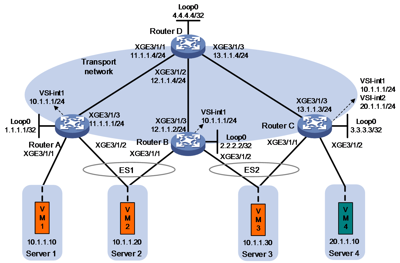
Procedure
1. On VM 1, VM 2, and VM 3, specify 10.1.1.1 as the gateway address. On VM 4, specify 20.1.1.1 as the gateway address. (Details not shown.)
2. Configure IP addresses and unicast routing settings:
# Assign IP addresses to the interfaces, as shown in Figure 22. (Details not shown.)
# Configure OSPF on all transport network routers (Routers A through D) for them to reach one another. (Details not shown.)
3. Configure Router A:
# Enable L2VPN.
<RouterA> system-view
[RouterA] l2vpn enable
# Disable remote MAC address learning and remote ARP learning.
[RouterA] vxlan tunnel mac-learning disable
[RouterA] vxlan tunnel arp-learning disable
# Create an EVPN instance on VSI vpna, and configure the router to automatically generate an RD and a route target for the EVPN instance.
[RouterA] vsi vpna
[RouterA-vsi-vpna] evpn encapsulation vxlan
[RouterA-vsi-vpna-evpn-vxlan] route-distinguisher auto router-id
[RouterA-vsi-vpna-evpn-vxlan] vpn-target auto
[RouterA-vsi-vpna-evpn-vxlan] quit
# Create VXLAN 10.
[RouterA-vsi-vpna] vxlan 10
[RouterA-vsi-vpna-vxlan-10] quit
[RouterA-vsi-vpna] quit
# Configure BGP to advertise BGP EVPN routes.
[RouterA] bgp 200
[RouterA-bgp-default] peer 4.4.4.4 as-number 200
[RouterA-bgp-default] peer 4.4.4.4 connect-interface loopback 0
[RouterA-bgp-default] address-family l2vpn evpn
[RouterA-bgp-default-evpn] peer 4.4.4.4 enable
[RouterA-bgp-default-evpn] quit
[RouterA-bgp-default] quit
# Map Ten-GigabitEthernet 3/1/1 to VSI vpna.
[RouterA] interface ten-gigabitethernet 3/1/1
[RouterA-Ten-GigabitEthernet3/1/1] xconnect vsi vpna
[RouterA-Ten-GigabitEthernet3/1/1] quit
# Assign an ESI to Ten-GigabitEthernet 3/1/2.
[RouterA] interface ten-gigabitethernet 3/1/2
[RouterA-Ten-GigabitEthernet3/1/2] esi 0.0.0.0.1
# Map Ten-GigabitEthernet 3/1/2 to VSI vpna.
[RouterA-Ten-GigabitEthernet3/1/2] xconnect vsi vpna
[RouterA-Ten-GigabitEthernet3/1/2] quit
# Configure RD and route target settings for VPN instance l3vpna.
[RouterA] ip vpn-instance l3vpna
[RouterA-vpn-instance-l3vpna] route-distinguisher 1:1
[RouterA-vpn-instance-l3vpna] address-family ipv4
[RouterA-vpn-ipv4-l3vpna] vpn-target 2:2
[RouterA-vpn-ipv4-l3vpna] quit
[RouterA-vpn-instance-l3vpna] address-family evpn
[RouterA-vpn-evpn-l3vpna] vpn-target 1:1
[RouterA-vpn-evpn-l3vpna] quit
[RouterA-vpn-instance-l3vpna] quit
# Configure VSI-interface 1.
[RouterA] interface vsi-interface 1
[RouterA-Vsi-interface1] ip binding vpn-instance l3vpna
[RouterA-Vsi-interface1] ip address 10.1.1.1 255.255.255.0
[RouterA-Vsi-interface1] mac-address 1-1-1
[RouterA-Vsi-interface1] distributed-gateway local
[RouterA-Vsi-interface1] local-proxy-arp enable
[RouterA-Vsi-interface1] quit
# Associate VSI-interface 3 with VPN instance l3vpna, and configure the L3 VXLAN ID as 1000 for the VPN instance.
[RouterA] interface vsi-interface 3
[RouterA-Vsi-interface3] ip binding vpn-instance l3vpna
[RouterA-Vsi-interface3] l3-vni 1000
[RouterA-Vsi-interface3] quit
# Specify VSI-interface 1 as the gateway interface for VSI vpna.
[RouterA] vsi vpna
[RouterA-vsi-vpna] gateway vsi-interface 1
[RouterA-vsi-vpna] quit
4. Configure Router B:
# Enable L2VPN.
<RouterB> system-view
[RouterB] l2vpn enable
# Disable remote MAC address learning and remote ARP learning.
[RouterB] vxlan tunnel mac-learning disable
[RouterB] vxlan tunnel arp-learning disable
# Create an EVPN instance on VSI vpna, and configure the router to automatically generate an RD and a route target for the EVPN instance.
[RouterB] vsi vpna
[RouterB-vsi-vpna] evpn encapsulation vxlan
[RouterB-vsi-vpna-evpn-vxlan] route-distinguisher auto router-id
[RouterB-vsi-vpna-evpn-vxlan] vpn-target auto
[RouterB-vsi-vpna-evpn-vxlan] quit
# Create VXLAN 10.
[RouterB-vsi-vpna] vxlan 10
[RouterB-vsi-vpna-vxlan-10] quit
[RouterB-vsi-vpna] quit
# Configure BGP to advertise BGP EVPN routes.
[RouterB] bgp 200
[RouterB-bgp-default] peer 4.4.4.4 as-number 200
[RouterB-bgp-default] peer 4.4.4.4 connect-interface loopback 0
[RouterB-bgp-default] address-family l2vpn evpn
[RouterB-bgp-default-evpn] peer 4.4.4.4 enable
[RouterB-bgp-default-evpn] quit
[RouterB-bgp-default] quit
# Assign an ESI to Ten-GigabitEthernet 3/1/1.
[RouterB] interface ten-gigabitethernet 3/1/1
[RouterB-Ten-GigabitEthernet3/1/1] esi 0.0.0.0.1
# Map Ten-GigabitEthernet 3/1/1 to VSI vpna.
[RouterB-Ten-GigabitEthernet3/1/1] xconnect vsi vpna
[RouterB-Ten-GigabitEthernet3/1/1] quit
# Assign an ESI to Ten-GigabitEthernet 3/1/2.
[RouterB] interface ten-gigabitethernet 3/1/2
[RouterB-Ten-GigabitEthernet3/1/2] esi 0.0.0.0.2
# Map Ten-GigabitEthernet 3/1/2 to VSI vpna.
[RouterB-Ten-GigabitEthernet3/1/2] xconnect vsi vpna
[RouterB-Ten-GigabitEthernet3/1/2] quit
# Configure RD and route target settings for VPN instance l3vpna.
[RouterB] ip vpn-instance l3vpna
[RouterB-vpn-instance-l3vpna] route-distinguisher 2:2
[RouterB-vpn-instance-l3vpna] address-family ipv4
[RouterB-vpn-ipv4-l3vpna] vpn-target 2:2
[RouterB-vpn-ipv4-l3vpna] quit
[RouterB-vpn-instance-l3vpna] address-family evpn
[RouterB-vpn-evpn-l3vpna] vpn-target 1:1
[RouterB-vpn-evpn-l3vpna] quit
[RouterB-vpn-instance-l3vpna] quit
# Configure VSI-interface 1.
[RouterB] interface vsi-interface 1
[RouterB-Vsi-interface1] ip binding vpn-instance l3vpna
[RouterB-Vsi-interface1] ip address 10.1.1.1 255.255.255.0
[RouterB-Vsi-interface1] mac-address 1-1-1
[RouterB-Vsi-interface1] distributed-gateway local
[RouterB-Vsi-interface1] local-proxy-arp enable
[RouterB-Vsi-interface1] quit
# Associate VSI-interface 3 with VPN instance l3vpna, and configure the L3 VXLAN ID as 1000 for the VPN instance.
[RouterB] interface vsi-interface 3
[RouterB-Vsi-interface3] ip binding vpn-instance l3vpna
[RouterB-Vsi-interface3] l3-vni 1000
[RouterB-Vsi-interface3] quit
# Specify VSI-interface 1 as the gateway interface for VSI vpna.
[RouterB] vsi vpna
[RouterB-vsi-vpna] gateway vsi-interface 1
[RouterB-vsi-vpna] quit
5. Configure Router C:
# Enable L2VPN.
<RouterC> system-view
[RouterC] l2vpn enable
# Disable remote MAC address learning and remote ARP learning.
[RouterC] vxlan tunnel mac-learning disable
[RouterC] vxlan tunnel arp-learning disable
# Create an EVPN instance on VSI vpna, and configure the router to automatically generate an RD and a route target for the EVPN instance.
[RouterC] vsi vpna
[RouterC-vsi-vpna] evpn encapsulation vxlan
[RouterC-vsi-vpna-evpn-vxlan] route-distinguisher auto router-id
[RouterC-vsi-vpna-evpn-vxlan] vpn-target auto
[RouterC-vsi-vpna-evpn-vxlan] quit
# Create VXLAN 10.
[RouterC-vsi-vpna] vxlan 10
[RouterC-vsi-vpna-vxlan-10] quit
[RouterC-vsi-vpna] quit
# Create an EVPN instance on VSI vpnb, and configure the router to automatically generate an RD and a route target for the EVPN instance.
[RouterC] vsi vpnb
[RouterC-vsi-vpnb] evpn encapsulation vxlan
[RouterC-vsi-vpnb-evpn-vxlan] route-distinguisher auto router-id
[RouterC-vsi-vpnb-evpn-vxlan] vpn-target auto
[RouterC-vsi-vpnb-evpn-vxlan] quit
# Create VXLAN 20.
[RouterC-vsi-vpnb] vxlan 20
[RouterC-vsi-vpnb-vxlan-20] quit
[RouterC-vsi-vpnb] quit
# Configure BGP to advertise BGP EVPN routes.
[RouterC] bgp 200
[RouterC-bgp-default] peer 4.4.4.4 as-number 200
[RouterC-bgp-default] peer 4.4.4.4 connect-interface loopback 0
[RouterC-bgp-default] address-family l2vpn evpn
[RouterC-bgp-default-evpn] peer 4.4.4.4 enable
[RouterC-bgp-default-evpn] quit
[RouterC-bgp-default] quit
# Assign an ESI to Ten-GigabitEthernet 3/1/1.
[RouterC] interface ten-gigabitethernet 3/1/1
[RouterC-Ten-GigabitEthernet3/1/1] esi 0.0.0.0.2
# Map Ten-GigabitEthernet 3/1/1 to VSI vpna.
[RouterC-Ten-GigabitEthernet3/1/1] xconnect vsi vpna
[RouterC-Ten-GigabitEthernet3/1/1] quit
# Map Ten-GigabitEthernet 3/1/2 to VSI vpnb.
[RouterC] interface ten-gigabitethernet 3/1/2
[RouterC-Ten-GigabitEthernet3/1/2] xconnect vsi vpnb
[RouterC-Ten-GigabitEthernet3/1/2] quit
# Configure RD and route target settings for VPN instance l3vpna.
[RouterC] ip vpn-instance l3vpna
[RouterC-vpn-instance-l3vpna] route-distinguisher 3:3
[RouterC-vpn-instance-l3vpna] address-family ipv4
[RouterC-vpn-ipv4-l3vpna] vpn-target 2:2
[RouterC-vpn-ipv4-l3vpna] quit
[RouterC-vpn-instance-l3vpna] address-family evpn
[RouterC-vpn-evpn-l3vpna] vpn-target 1:1
[RouterC-vpn-evpn-l3vpna] quit
[RouterC-vpn-instance-l3vpna] quit
# Configure VSI-interface 1.
[RouterC] interface vsi-interface 1
[RouterC-Vsi-interface1] ip binding vpn-instance l3vpna
[RouterC-Vsi-interface1] ip address 10.1.1.1 255.255.255.0
[RouterC-Vsi-interface1] mac-address 1-1-1
[RouterC-Vsi-interface1] distributed-gateway local
[RouterC-Vsi-interface1] local-proxy-arp enable
[RouterC-Vsi-interface1] quit
# Configure VSI-interface 2.
[RouterC] interface vsi-interface 2
[RouterC-Vsi-interface2] ip binding vpn-instance l3vpna
[RouterC-Vsi-interface2] ip address 20.1.1.1 255.255.255.0
[RouterC-Vsi-interface2] mac-address 2-2-2
[RouterC-Vsi-interface2] distributed-gateway local
[RouterC-Vsi-interface2] local-proxy-arp enable
[RouterC-Vsi-interface2] quit
# Associate VSI-interface 3 with VPN instance l3vpna, and configure the L3 VXLAN ID as 1000 for the VPN instance.
[RouterC] interface vsi-interface 3
[RouterC-Vsi-interface3] ip binding vpn-instance l3vpna
[RouterC-Vsi-interface3] l3-vni 1000
[RouterC-Vsi-interface3] quit
# Specify VSI-interface 1 as the gateway interface for VSI vpna.
[RouterC] vsi vpna
[RouterC-vsi-vpna] gateway vsi-interface 1
[RouterC-vsi-vpna] quit
# Specify VSI-interface 2 as the gateway interface for VSI vpnb.
[RouterC] vsi vpnb
[RouterC-vsi-vpnb] gateway vsi-interface 2
[RouterC-vsi-vpnb] quit
6. Configure Router D:
# Establish BGP connections with other transport network routers.
<RouterD> system-view
[RouterD] bgp 200
[RouterD-bgp-default] group evpn
[RouterD-bgp-default] peer 1.1.1.1 group evpn
[RouterD-bgp-default] peer 2.2.2.2 group evpn
[RouterD-bgp-default] peer 3.3.3.3 group evpn
[RouterD-bgp-default] peer evpn as-number 200
[RouterD-bgp-default] peer evpn connect-interface loopback 0
# Configure BGP to advertise BGP EVPN routes, and disable route target filtering for BGP EVPN routes.
[RouterD-bgp-default] address-family l2vpn evpn
[RouterD-bgp-default-evpn] peer evpn enable
[RouterD-bgp-default-evpn] undo policy vpn-target
# Configure Router D as an RR.
[RouterD-bgp-default-evpn] peer evpn reflect-client
[RouterD-bgp-default-evpn] quit
[RouterD-bgp-default] quit
Verifying the configuration
1. Verify the EVPN VXLAN multihoming configuration on Router C. (Details not shown.)
# Verify that Router C has advertised and received the following BGP EVPN routes:
¡ IP prefix advertisement routes for the gateways.
¡ IMET routes for VSIs.
¡ MAC/IP advertisement routes.
¡ Ethernet auto-discovery routes and Ethernet segment routes.
# Verify that Router C has ECMP routes to VM 2.
<RouterC> display evpn routing-table vpn-instance l3vpna
Flags: E - with valid ESI A - AD ready L - Local ES exists
VPN instance:l3vpna Local L3VNI:1000
IP address Next hop Outgoing interface NibID Flags
10.1.1.10 1.1.1.1 Vsi-interface3 0x18000001 -
10.1.1.20 2.2.2.2 Vsi-interface3 0x18000000 EA
1.1.1.1 Vsi-interface3 0x18000001 EA
# Verify that Router C has equal-cost L2VPN MAC address entries and EVPN MAC address entries for VM 2.
<RouterC> display l2vpn mac-address
MAC Address State VSI Name Link ID/Name/Peer
Aging
0001-0001-0010 EVPN vpna Tunnel0
NotAging
0001-0001-0020 EVPN vpna Tunnel0
NotAging
Tunnel1
NotAging
0001-0001-0030 Dynamic vpna 0x0
NotAging
0002-0001-0010 Dynamic vpnb 0x0
NotAging
<RouterC> display evpn route mac
Flags: D - Dynamic B - BGP L - Local active
G - Gateway S - Static M - Mapping I - Invalid
E – Multihoming ES sync
VSI name: vpna
MAC address Link ID/Name Flags Encap Next hop
0001-0001-0030 0 DL VXLAN -
0001-0001-0010 Tunnel0 B VXLAN 1.1.1.1
0001-0001-0020 Tunnel0 B VXLAN 1.1.1.1
Tunnel1 B VXLAN 2.2.2.2
VSI name: vpnb
MAC address Link ID/Name Flags Next hop
0002-0001-0010 0 DL -
# Verify that Router C has information about local and remote ESs.
<RouterC> display evpn es local
Redundancy mode: A - All active, S - Single active
VSI name : vpna
ESI Tag ID DF address Mode State ESI label
0000.0000.0000.0000.0002 0 2.2.2.2 A Up -
<RouterC> display evpn es remote
Control Flags: P - Primary, B - Backup, C - Control word
VSI name : vpna
ESI : 0000.0000.0000.0000.0001
A-D per ES routes :
Peer IP Remote Redundancy mode
1.1.1.1 All-active
2.2.2.2 All-active
A-D per EVI routes :
Tag ID Peer IP
0 1.1.1.1
0 2.2.2.2
ESI : 0000.0000.0000.0000.0002
Ethernet segment routes :
2.2.2.2
A-D per ES routes :
Peer IP Remote Redundancy mode
2.2.2.2 All-active
A-D per EVI routes :
Tag ID Peer IP
0 2.2.2.2
2. Verify that the VMs can communicate with one another.
Example: Interconnecting an EVPN VXLAN network with a VPLS network
Network configuration
As shown in Figure 23, interconnect the EVPN VXLAN network with the VPLS network as follows:
· Set up LDP PWs as UPWs by using LDP signaling between the gateways and the PE.
· Set up VXLAN tunnels between the gateways and the VTEP.
· Map the UPWs to the VXLAN tunnels on the gateways.
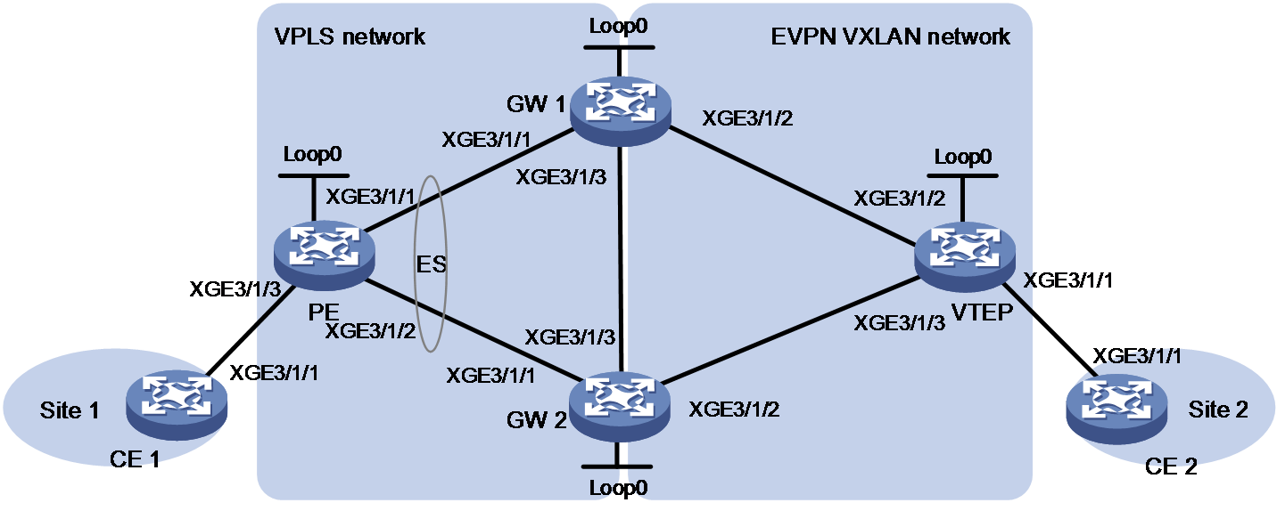
|
Device |
Interface |
IP address |
Device |
Interface |
IP address |
|
GW 1 |
Loop0 |
1.1.1.9/32 |
VTEP |
Loop0 |
3.3.3.9/32 |
|
|
XGE3/1/1 |
10.1.1.1/24 |
|
XGE3/1/1 |
- |
|
|
XGE3/1/2 |
30.1.1.1/24 |
|
XGE3/1/2 |
30.1.1.3/24 |
|
|
XGE3/1/3 |
10.1.3.1/24 |
|
XGE3/1/3 |
10.1.2.3/24 |
|
GW 2 |
Loop0 |
2.2.2.9/32 |
PE |
Loop0 |
4.4.4.9/32 |
|
|
XGE3/1/1 |
20.1.1.2/24 |
|
XGE3/1/3 |
- |
|
|
XGE3/1/2 |
10.1.2.2/24 |
|
XGE3/1/1 |
10.1.1.4/24 |
|
|
XGE3/1/3 |
10.1.3.2/24 |
|
XGE3/1/2 |
20.1.1.4/24 |
|
CE 1 |
XGE3/1/1 |
100.1.1.1/32 |
CE 2 |
XGE3/1/1 |
100.1.1.2/32 |
Procedure
1. Configure CE 1:
# Assign an IP address to Ten-GigabitEthernet 3/1/1.
<CE1> system-view
[CE1] interface ten-gigabitethernet 3/1/1
[CE1-Ten-GigabitEthernet3/1/1] ip address 100.1.1.1 24
[CE1-Ten-GigabitEthernet3/1/1] quit
2. Configure the PE:
# Configure basic MPLS capabilities.
<PE> system-view
[PE] interface loopback 0
[PE-LoopBack0] ip address 4.4.4.9 32
[PE-LoopBack0] ospf 1 area 0
[PE-LoopBack0] quit
[PE] mpls lsr-id 4.4.4.9
# Enable LDP globally.
[PE] mpls ldp
[PE-ldp] quit
# Enable L2VPN.
[PE] l2vpn enable
# Configure Ten-GigabitEthernet 3/1/1 that is connected to GW 1.
[PE] interface ten-gigabitethernet 3/1/1
[PE-Ten-GigabitEthernet3/1/1] ip address 10.1.1.4 24
[PE-Ten-GigabitEthernet3/1/1] ospf 1 area 0
[PE-Ten-GigabitEthernet3/1/1] mpls enable
[PE-Ten-GigabitEthernet3/1/1] mpls ldp enable
[PE-Ten-GigabitEthernet3/1/1] undo shutdown
[PE-Ten-GigabitEthernet3/1/1] quit
# Configure Ten-GigabitEthernet 3/1/2 that is connected to GW 2.
[PE] interface ten-gigabitethernet 3/1/2
[PE-Ten-GigabitEthernet3/1/2] ip address 20.1.1.4 24
[PE-Ten-GigabitEthernet3/1/2] ospf 1 area 0
[PE-Ten-GigabitEthernet3/1/2] mpls enable
[PE-Ten-GigabitEthernet3/1/2] mpls ldp enable
[PE-Ten-GigabitEthernet3/1/2] undo shutdown
[PE-Ten-GigabitEthernet3/1/2] quit
# Specify LDP signaling for VSI vpna, set up a main PW to GW 1 and a backup PW to GW 2, and enable the dual receive feature for PW redundancy.
[PE] vsi vpna
[PE-vsi-vpna] protection dual-receive
[PE-vsi-vpna] pwsignaling ldp
[PE-vsi-vpna-ldp] peer 1.1.1.9 pw-id 500
[PE-vsi-vpna-ldp-1.1.1.9-500] backup-peer 2.2.2.9 pw-id 500
[PE-vsi-vpna-ldp-1.1.1.9-500-backup] quit
[PE-vsi-vpna-ldp-1.1.1.9-500] quit
[PE-vsi-vpna-ldp] quit
[PE-vsi-vpna] quit
# Map Ten-GigabitEthernet 3/1/3 to VSI aaa.
[PE] interface ten-gigabitethernet 3/1/3
[PE-Ten-GigabitEthernet3/1/3] xconnect vsi vpna
[PE-Ten-GigabitEthernet3/1/3] quit
3. Configure the GW 1:
# Configure Loopback 0.
<GW1> system-view
[GW1] interface loopback 0
[GW1-LoopBack1] ip address 1.1.1.9 32
[GW1-LoopBack1] quit
# Configure basic MPLS capabilities.
[GW1] mpls lsr-id 1.1.1.9
# Enable LDP globally.
[GW1] mpls ldp
[GW1-ldp] quit
# Enable L2VPN.
[GW1] l2vpn enable
# Run OSPF for setting up LSPs.
[GW1] ospf
[GW1-ospf-1] area 0
[GW1-ospf-1-area-0.0.0.0] network 10.1.1.0 0.0.0.255
[GW1-ospf-1-area-0.0.0.0] network 30.1.1.0 0.0.0.255
[GW1-ospf-1-area-0.0.0.0] network 10.1.3.0 0.0.0.255
[GW1-ospf-1-area-0.0.0.0] network 1.1.1.9 0.0.0.0
[GW1-ospf-1] quit
# Configure Ten-GigabitEthernet 3/1/1 that is connected to the PE.
[GW1] interface ten-gigabitethernet 3/1/1
[GW1-Ten-GigabitEthernet3/1/1] ip address 10.1.1.1 24
[GW1-Ten-GigabitEthernet3/1/1] mpls enable
[GW1-Ten-GigabitEthernet3/1/1] mpls ldp enable
[GW1-Ten-GigabitEthernet3/1/1] undo shutdown
[GW1-Ten-GigabitEthernet3/1/1] quit
# Configure Ten-GigabitEthernet 3/1/2 that is connected to the VTEP.
[GW1] interface ten-gigabitethernet 3/1/2
[GW1-Ten-GigabitEthernet3/1/2] ip address 30.1.1.1 24
[GW1-Ten-GigabitEthernet3/1/2] mpls enable
[GW1-Ten-GigabitEthernet3/1/2] mpls ldp enable
[GW1-Ten-GigabitEthernet3/1/2] undo shutdown
[GW1-Ten-GigabitEthernet3/1/2] quit
# Configure Ten-GigabitEthernet 3/1/3 that is connected to GW 2.
[GW1] interface ten-gigabitethernet 3/1/3
[GW1-Ten-GigabitEthernet3/1/3] ip address 10.1.3.1 24
[GW1-Ten-GigabitEthernet3/1/3] mpls enable
[GW1-Ten-GigabitEthernet3/1/3] mpls ldp enable
[GW1-Ten-GigabitEthernet3/1/3] undo shutdown
[GW1-Ten-GigabitEthernet3/1/3] quit
# Set up IBGP connections among GW 1, GW 2, and the VTEP, and enable advertisement of BGP EVPN routes.
[GW1] bgp 100
[GW1-bgp-default] peer 2.2.2.9 as-number 100
[GW1-bgp-default] peer 2.2.2.9 connect-interface loopback 0
[GW1-bgp-default] peer 3.3.3.9 as-number 100
[GW1-bgp-default] peer 3.3.3.9 connect-interface loopback 0
[GW1-bgp-default] address-family l2vpn evpn
[GW1-bgp-default-evpn] peer 2.2.2.9 enable
[GW1-bgp-default-evpn] peer 3.3.3.9 enable
[GW1-bgp-default-evpn] quit
[GW1-bgp-default] quit
# Create VSI vpna, and create an EVPN instance on it. Configure the VSI EVPN instance to use VXLAN encapsulation, and configure an RD and route targets for the VSI EVPN instance.
[GW1] vsi vpna
[GW1-vsi-vpna] vxlan 10
[GW1-vsi-vpna] evpn encapsulation vxlan
[GW1-vsi-vpna-evpn-vxlan] route-distinguisher 1:1
[GW1-vsi-vpna-evpn-vxlan] vpn-target 1:1 export-extcommunity
[GW1-vsi-vpna-evpn-vxlan] vpn-target 1:1 import-extcommunity
[GW1-vsi-vpna-evpn-vxlan] quit
# Specify LDP signaling for VSI vpna, set up a UPW to GW 1, and configure the ESI and redundancy mode for the VSI.
[GW1-vsi-vpna] pwsignaling ldp
[GW1-vsi-vpna-ldp] peer 4.4.4.9 pw-id 500 no-split-horizon
[GW1-vsi-vpna-ldp-4.4.4.9-500] esi 1.1.1.1.1
[GW1-vsi-vpna-ldp-4.4.4.9-500] evpn redundancy-mode all-active
[GW1-vsi-vpna-ldp-4.4.4.9-500] quit
[GW1-vsi-vpna-ldp] quit
[GW1-vsi-vpna] quit
4. Configure the GW 2:
# Configure basic MPLS capabilities.
<GW2> system-view
[GW2] interface loopback 0
[GW2-LoopBack0] ip address 2.2.2.9 32
[GW2-LoopBack0] quit
[GW2] mpls lsr-id 2.2.2.9
# Enable LDP globally.
[GW2] mpls ldp
[GW2-ldp] quit
# Enable L2VPN.
[GW2] l2vpn enable
# Run OSPF for setting up LSPs.
[GW2] ospf
[GW2-ospf-1] area 0
[GW2-ospf-1-area-0.0.0.0] network 10.1.2.0 0.0.0.255
[GW2-ospf-1-area-0.0.0.0] network 20.1.1.0 0.0.0.255
[GW2-ospf-1-area-0.0.0.0] network 10.1.3.0 0.0.0.255
[GW2-ospf-1-area-0.0.0.0] network 2.2.2.9 0.0.0.0
[GW2-ospf-1] quit
# Configure Ten-GigabitEthernet 3/1/3 that is connected to GW 1.
[GW2] interface ten-gigabitethernet 3/1/3
[GW2-Ten-GigabitEthernet3/1/3] ip address 10.1.3.2 24
[GW2-Ten-GigabitEthernet3/1/3] mpls enable
[GW2-Ten-GigabitEthernet3/1/3] mpls ldp enable
[GW2-Ten-GigabitEthernet3/1/3] undo shutdown
[GW2-Ten-GigabitEthernet3/1/3] quit
# Configure Ten-GigabitEthernet 3/1/2 that is connected to the VTEP.
[GW2] interface ten-gigabitethernet 3/1/2
[GW2-Ten-GigabitEthernet3/1/2] ip address 10.1.2.1 24
[GW2-Ten-GigabitEthernet3/1/2] mpls enable
[GW2-Ten-GigabitEthernet3/1/2] mpls ldp enable
[GW2-Ten-GigabitEthernet3/1/2] undo shutdown
[GW2-Ten-GigabitEthernet3/1/2] quit
# Configure Ten-GigabitEthernet 3/1/1 that is connected to the PE.
[GW2] interface ten-gigabitethernet 3/1/1
[GW2-Ten-GigabitEthernet3/1/1] ip address 20.1.1.2 24
[GW2-Ten-GigabitEthernet3/1/1] mpls enable
[GW2-Ten-GigabitEthernet3/1/1] mpls ldp enable
[GW2-Ten-GigabitEthernet3/1/1] undo shutdown
[GW2-Ten-GigabitEthernet3/1/1] quit
# Set up IBGP connections among GW 1, GW 2, and the VTEP, and enable advertisement of BGP EVPN routes.
[GW2] bgp 100
[GW2-bgp-default] peer 1.1.1.9 as-number 100
[GW2-bgp-default] peer 1.1.1.9 connect-interface loopback 0
[GW2-bgp-default] peer 3.3.3.9 as-number 100
[GW2-bgp-default] peer 3.3.3.9 connect-interface loopback 0
[GW2-bgp-default] address-family l2vpn evpn
[GW2-bgp-default-evpn] peer 1.1.1.9 enable
[GW2-bgp-default-evpn] peer 3.3.3.9 enable
[GW2-bgp-default-evpn] quit
[GW2-bgp-default] quit
# Create VSI vpna, and create an EVPN instance on it. Configure the VSI EVPN instance to use VXLAN encapsulation, and configure an RD and route targets for the VSI EVPN instance.
[GW2] vsi vpna
[GW2-vsi-vpna] vxlan 10
[GW2-vsi-vpna] evpn encapsulation vxlan
[GW2-vsi-vpna-evpn-vxlan] route-distinguisher 1:1
[GW2-vsi-vpna-evpn-vxlan] vpn-target 1:1 export-extcommunity
[GW2-vsi-vpna-evpn-vxlan] vpn-target 1:1 import-extcommunity
[GW2-vsi-vpna-evpn-vxlan] quit
# Specify LDP signaling for VSI vpna, set up a UPW to GW 2, and configure the ESI and redundancy mode for the VSI.
[GW2] vsi vpna
[GW2-vsi-vpna] pwsignaling ldp
[GW2-vsi-vpna-ldp] peer 1.1.1.9 pw-id 500 no-split-horizon
[GW2-vsi-vpna-ldp-1.1.1.9-500] esi 1.1.1.1.1
[GW2-vsi-vpna-ldp-1.1.1.9-500] evpn redundancy-mode all-active
[GW2-vsi-vpna-ldp-1.1.1.9-500] quit
[GW2-vsi-vpna-ldp] quit
[GW2-vsi-vpna] quit
5. Configure the VTEP:
# Configure basic MPLS capabilities.
<VTEP> system-view
[VTEP] interface loopback 0
[VTEP-LoopBack0] ip address 3.3.3.9 32
[VTEP-LoopBack0] quit
[VTEP] mpls lsr-id 3.3.3.9
# Enable LDP globally.
[VTEP] mpls ldp
[VTEP-ldp] quit
# Enable L2VPN.
[VTEP] l2vpn enable
# Run OSPF for setting up LSPs.
[VTEP] ospf
[VTEP-ospf-1] area 0
[VTEP-ospf-1-area-0.0.0.0] network 10.1.2.0 0.0.0.255
[VTEP-ospf-1-area-0.0.0.0] network 30.1.1.0 0.0.0.255
[VTEP-ospf-1-area-0.0.0.0] network 3.3.3.9 0.0.0.0
[VTEP-ospf-1] quit
# Configure Ten-GigabitEthernet 3/1/2 that is connected to GW 1.
[VTEP] interface ten-gigabitethernet 3/1/2
[VTEP-Ten-GigabitEthernet3/1/2] ip address 30.1.1.3 24
[VTEP-Ten-GigabitEthernet3/1/2] undo shutdown
[VTEP-Ten-GigabitEthernet3/1/2] quit
# Configure Ten-GigabitEthernet 3/1/3 that is connected to GW 2.
[VTEP] interface ten-gigabitethernet 3/1/3
[VTEP-Ten-GigabitEthernet3/1/3] ip address 10.1.2.3 24
[VTEP-Ten-GigabitEthernet3/1/3] undo shutdown
[VTEP-Ten-GigabitEthernet3/1/3] quit
# Set up IBGP connections among GW 1, GW 2, and the VTEP, and enable advertisement of BGP EVPN routes.
[VTEP] bgp 100
[VTEP-bgp-default] peer 1.1.1.9 as-number 100
[VTEP-bgp-default] peer 1.1.1.9 connect-interface loopback 0
[VTEP-bgp-default] peer 2.2.2.9 as-number 100
[VTEP-bgp-default] peer 2.2.2.9 connect-interface loopback 0
[VTEP-bgp-default] address-family l2vpn evpn
[VTEP-bgp-default-evpn] peer 1.1.1.9 enable
[VTEP-bgp-default-evpn] peer 2.2.2.9 enable
[VTEP-bgp-default-evpn] quit
[VTEP-bgp-default] quit
# Create VSI vpna, and create an EVPN instance on it. Configure the VSI EVPN instance to use VXLAN encapsulation, and configure an RD and route targets for the VSI EVPN instance.
[VTEP] vsi vpna
[VTEP-vsi-vpna] vxlan 10
[VTEP-vsi-vpna] evpn encapsulation vxlan
[VTEP-vsi-vpna-evpn-vxlan] route-distinguisher 1:1
[VTEP-vsi-vpna-evpn-vxlan] vpn-target 1:1 export-extcommunity
[VTEP-vsi-vpna-evpn-vxlan] vpn-target 1:1 import-extcommunity
[VTEP-vsi-vpna-evpn-vxlan] quit
# Map Ten-GigabitEthernet 3/1/1 to VSI vpna.
[VTEP] interface ten-gigabitethernet 3/1/1
[VTEP-Ten-GigabitEthernet3/1/1] xconnect vsi vpna
[VTEP-Ten-GigabitEthernet3/1/1] quit
6. Configure CE 2:
# Assign an IP address to Ten-GigabitEthernet 3/1/1.
<CE2> system-view
[CE2] interface ten-gigabitethernet 3/1/1
[CE2-Ten-GigabitEthernet3/1/1] ip address 100.1.1.2 24
[CE2-Ten-GigabitEthernet3/1/1] quit
Verifying the configuration
# Verify that GW 1 has established an LDP PW with the PE and VXLAN tunnels with GW 2 and the VTEP.
<GW1> display l2vpn pw
Flags: M - main, B - backup, E - ecmp, BY - bypass, H - hub link, S - spoke link
N - no split horizon, A - administration, ABY - ac-bypass
PBY - pw-bypass
Total number of PWs: 3
1 up, 0 blocked, 0 down, 0 defect, 0 idle, 0 duplicate
VSI Name: vpna
Peer PWID/RmtSite/SrvID In/Out Label Proto Flag Link ID State
4.4.4.9 500 1147/- LDP MN 8 Up
[GW1] display vxlan tunnel
Total number of VXLANs: 2
VXLAN ID: 10, VSI name: vpna, Total tunnels: 2 (2 up, 0 down, 0 defect, 0 blocked)
Tunnel name Link ID State Type Flood Proxy
Tunnel0 0x5000000 UP Auto Disabled
Tunnel1 0x5000001 UP Auto Disabled
# Verify that GW 1 has a UPW (LDP PW) used for multihoming.
<GW1> display evpn es local verbose
VSI name : vpna
ESI : 0001.0001.0001.0001.0001
Interface : -
Redundancy mode : All-active
State : Up
UPWs :
Link ID Service instance ID Tag ID DF address ESI label
8 - 0 - 1146
# Verify that GW 2 has similar configuration to GW 1. (Details not shown.)
# Verify that CE 1 and CE 2 can ping each other. (Details not shown.)
Example: Interconnecting an EVPN VXLAN network with an EVPN VPLS network
Network configuration
As shown in Figure 24, interconnect the EVPN VXLAN network with the EVPN VPLS network as follows:
· Set up PWs between the gateways and the PE.
· Set up VXLAN tunnels between the gateways and the VTEP.
· Configure the gateways to exchange BGP EVPN routes between the EVPN VXLAN network and the EVPN VPLS network.
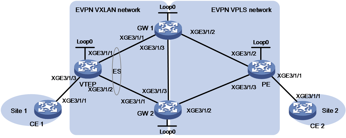
|
Device |
Interface |
IP address |
Device |
Interface |
IP address |
|
GW 1 |
Loop0 |
1.1.1.9/32 |
PE |
Loop0 |
3.3.3.9/32 |
|
|
XGE3/1/1 |
10.1.1.1/24 |
|
XGE3/1/1 |
- |
|
|
XGE3/1/2 |
30.1.1.1/24 |
|
XGE3/1/2 |
30.1.1.3/24 |
|
|
XGE3/1/3 |
10.1.3.1/24 |
|
XGE3/1/3 |
10.1.2.3/24 |
|
GW 2 |
Loop0 |
2.2.2.9/32 |
VTEP |
Loop0 |
4.4.4.9/32 |
|
|
XGE3/1/1 |
20.1.1.2/24 |
|
XGE3/1/3 |
- |
|
|
XGE3/1/2 |
10.1.2.2/24 |
|
XGE3/1/1 |
10.1.1.4/24 |
|
|
XGE3/1/3 |
10.1.3.2/24 |
|
XGE3/1/2 |
20.1.1.4/24 |
|
CE 1 |
XGE3/1/1 |
100.1.1.1/32 |
CE 2 |
XGE3/1/1 |
100.1.1.2/32 |
Procedure
1. Configure CE 1:
# Assign an IP address to Ten-GigabitEthernet 3/1/1.
<CE1> system-view
[CE1] interface ten-gigabitethernet 3/1/1
[CE1-Ten-GigabitEthernet3/1/1] ip address 100.1.1.1 24
[CE1-Ten-GigabitEthernet3/1/1] quit
2. Configure the VTEP:
# Configure loopback interface 0.
<VTEP> system-view
[VTEP] interface loopback 0
[VTEP-LoopBack0] ip address 4.4.4.9 32
[VTEP-LoopBack0] quit
# Enable L2VPN.
[VTEP] l2vpn enable
# Configure Ten-GigabitEthernet 3/1/1 that is connected to GW 1.
[VTEP] interface ten-gigabitethernet 3/1/1
[VTEP-Ten-GigabitEthernet3/1/1] ip address 10.1.1.4 24
[VTEP-Ten-GigabitEthernet3/1/1] ospf 1 area 0
[VTEP-Ten-GigabitEthernet3/1/1] undo shutdown
[VTEP-Ten-GigabitEthernet3/1/1] quit
# Configure Ten-GigabitEthernet 3/1/2 that is connected to GW 2.
[VTEP] interface ten-gigabitethernet 3/1/2
[VTEP-Ten-GigabitEthernet3/1/2] ip address 20.1.1.4 24
[VTEP-Ten-GigabitEthernet3/1/2] ospf 1 area 0
[VTEP-Ten-GigabitEthernet3/1/2] undo shutdown
[VTEP-Ten-GigabitEthernet3/1/2] quit
# Set up IBGP peer relationships with GW 1 and GW 2, and configure the VTEP to advertise BGP EVPN routes.
[VTEP] bgp 100
[VTEP-bgp-default] peer 1.1.1.9 as-number 100
[VTEP-bgp-default] peer 1.1.1.9 connect-interface loopback 0
[VTEP-bgp-default] peer 2.2.2.9 as-number 100
[VTEP-bgp-default] peer 2.2.2.9 connect-interface loopback 0
[VTEP-bgp-default] address-family l2vpn evpn
[VTEP-bgp-default-evpn] peer 1.1.1.9 enable
[VTEP-bgp-default-evpn] peer 2.2.2.9 enable
[VTEP-bgp-default-evpn] quit
[VTEP-bgp-default] quit
# Configure EVPN instance vxlan.
[VTEP] evpn instance vxlan
[VTEP-evpn-instance-vxlan] route-distinguisher 11:2
[VTEP-evpn-instance-vxlan] vpn-target 11:2 export-extcommunity
[VTEP-evpn-instance-vxlan] vpn-target 11:2 import-extcommunity
[VTEP-evpn-instance-vxlan] quit
# Associate VSI vxlan with an EVPN instance that uses VXLAN encapsulation.
[VTEP] vsi vxlan
[VTEP-vsi-vxlan] evpn encapsulation vxlan binding instance vxlan
[VTEP-vsi-vxlan] vxlan 10
[VTEP-vsi-vxlan-vxlan-10] quit
[VTEP-vsi-vxlan] quit
# Map Ten-GigabitEthernet 3/1/3 to VSI vxlan.
[VTEP] interface ten-gigabitethernet 3/1/3
[VTEP-Ten-GigabitEthernet3/1/3] xconnect vsi vxlan
[VTEP-Ten-GigabitEthernet3/1/3] quit
3. Configure the GW 1:
# Configure Loopback 0.
<GW1> system-view
[GW1] interface loopback 0
[GW1-LoopBack1] ip address 1.1.1.9 32
[GW1-LoopBack1] quit
# Configure basic MPLS capabilities.
[GW1] mpls lsr-id 1.1.1.9
# Enable LDP globally.
[GW1] mpls ldp
[GW1-ldp] quit
# Enable L2VPN.
[GW1] l2vpn enable
# Run OSPF for setting up LSPs.
[GW1] ospf
[GW1-ospf-1] area 0
[GW1-ospf-1-area-0.0.0.0] network 10.1.1.0 0.0.0.255
[GW1-ospf-1-area-0.0.0.0] network 30.1.1.0 0.0.0.255
[GW1-ospf-1-area-0.0.0.0] network 10.1.3.0 0.0.0.255
[GW1-ospf-1-area-0.0.0.0] network 1.1.1.9 0.0.0.0
[GW1-ospf-1] quit
# Configure Ten-GigabitEthernet 3/1/1 that is connected to the VTEP.
[GW1] interface ten-gigabitethernet 3/1/1
[GW1-Ten-GigabitEthernet3/1/1] ip address 10.1.1.1 24
[GW1-Ten-GigabitEthernet3/1/1] mpls enable
[GW1-Ten-GigabitEthernet3/1/1] mpls ldp enable
[GW1-Ten-GigabitEthernet3/1/1] undo shutdown
[GW1-Ten-GigabitEthernet3/1/1] quit
# Configure Ten-GigabitEthernet 3/1/2 that is connected to the PE.
[GW1] interface ten-gigabitethernet 3/1/2
[GW1-Ten-GigabitEthernet3/1/2] ip address 30.1.1.1 24
[GW1-Ten-GigabitEthernet3/1/2] mpls enable
[GW1-Ten-GigabitEthernet3/1/2] mpls ldp enable
[GW1-Ten-GigabitEthernet3/1/2] undo shutdown
[GW1-Ten-GigabitEthernet3/1/2] quit
# Configure Ten-GigabitEthernet 3/1/3 that is connected to GW 2.
[GW1] interface ten-gigabitethernet 3/1/3
[GW1-Ten-GigabitEthernet3/1/3] ip address 10.1.3.1 24
[GW1-Ten-GigabitEthernet3/1/3] mpls enable
[GW1-Ten-GigabitEthernet3/1/3] mpls ldp enable
[GW1-Ten-GigabitEthernet3/1/3] undo shutdown
[GW1-Ten-GigabitEthernet3/1/3] quit
# Set up IBGP connections to GW 2, the VTEP, and the PE. Enable advertisement of BGP EVPN routes, and enable reorigination of MAC/IP advertisement routes.
[GW1] bgp 100
[GW1-bgp-default] evpn mac re-originated enable
[GW1-bgp-default] peer 2.2.2.9 as-number 100
[GW1-bgp-default] peer 2.2.2.9 connect-interface loopback 0
[GW1-bgp-default] peer 3.3.3.9 as-number 100
[GW1-bgp-default] peer 3.3.3.9 connect-interface loopback 0
[GW1-bgp-default] peer 4.4.4.9 as-number 100
[GW1-bgp-default] peer 4.4.4.9 connect-interface loopback 0
[GW1-bgp-default] address-family l2vpn evpn
[GW1-bgp-default-evpn] peer 2.2.2.9 enable
[GW1-bgp-default-evpn] peer 3.3.3.9 enable
[GW1-bgp-default-evpn] peer 3.3.3.9 advertise encap-type mpls
[GW1-bgp-default-evpn] peer 3.3.3.9 re-originated mac replace-rt
[GW1-bgp-default-evpn] peer 4.4.4.9 enable
[GW1-bgp-default-evpn] peer 4.4.4.9 re-originated mac replace-rt
[GW1-bgp-default-evpn] quit
[GW1-bgp-default] quit
# Configure EVPN instance evpna and EVPN instance evpnb.
[GW1] evpn instance evpna
[GW1-evpn-instance-evpna] route-distinguisher 11:1
[GW1-evpn-instance-evpna] vpn-target 11:1 export-extcommunity
[GW1-evpn-instance-evpna] vpn-target 11:1 import-extcommunity
[GW1-evpn-instance-evpna] quit
[GW1] evpn instance evpnb
[GW1-evpn-instance-evpnb] route-distinguisher 11:2
[GW1-evpn-instance-evpnb] vpn-target 11:2 export-extcommunity
[GW1-evpn-instance-evpnb] vpn-target 11:2 import-extcommunity
[GW1-evpn-instance-evpnb] quit
# Configure EVPN instance evpna to use MPLS encapsulation and EVPN instance evpnb to use VXLAN encapsulation. Bind the EVPN instances to VSI vpna, and assign an ESI to the VSI.
[GW1] vsi vpna
[GW1-vsi-vpna] evpn encapsulation mpls binding instance evpna
[GW1-vsi-vpna] evpn encapsulation vxlan binding instance evpnb
[GW1-vsi-vpna] vxlan 10
[GW1-vsi-vpna-vxlan-10] quit
[GW1-vsi-vpna] esi 1.1.1.1.1
[GW1-vsi-vpna] quit
4. Configure the GW 2:
# Configure basic MPLS capabilities.
<GW2> system-view
[GW2] interface loopback 0
[GW2-LoopBack0] ip address 2.2.2.9 32
[GW2-LoopBack0] quit
[GW2] mpls lsr-id 2.2.2.9
# Enable LDP globally.
[GW2] mpls ldp
[GW2-ldp] quit
# Enable L2VPN.
[GW2] l2vpn enable
# Run OSPF for setting up LSPs.
[GW2] ospf
[GW2-ospf-1] area 0
[GW2-ospf-1-area-0.0.0.0] network 10.1.2.0 0.0.0.255
[GW2-ospf-1-area-0.0.0.0] network 20.1.1.0 0.0.0.255
[GW2-ospf-1-area-0.0.0.0] network 10.1.3.0 0.0.0.255
[GW2-ospf-1-area-0.0.0.0] network 2.2.2.9 0.0.0.0
[GW2-ospf-1] quit
# Configure Ten-GigabitEthernet 3/1/3 that is connected to GW 1.
[GW2] interface ten-gigabitethernet 3/1/3
[GW2-Ten-GigabitEthernet3/1/3] ip address 10.1.3.2 24
[GW2-Ten-GigabitEthernet3/1/3] mpls enable
[GW2-Ten-GigabitEthernet3/1/3] mpls ldp enable
[GW2-Ten-GigabitEthernet3/1/3] undo shutdown
[GW2-Ten-GigabitEthernet3/1/3] quit
# Configure Ten-GigabitEthernet 3/1/2 that is connected to the PE.
[GW2] interface ten-gigabitethernet 3/1/2
[GW2-Ten-GigabitEthernet3/1/2] ip address 10.1.2.1 24
[GW2-Ten-GigabitEthernet3/1/2] mpls enable
[GW2-Ten-GigabitEthernet3/1/2] mpls ldp enable
[GW2-Ten-GigabitEthernet3/1/2] undo shutdown
[GW2-Ten-GigabitEthernet3/1/2] quit
# Configure Ten-GigabitEthernet 3/1/1 that is connected to the VTEP.
[GW2] interface ten-gigabitethernet 3/1/1
[GW2-Ten-GigabitEthernet3/1/1] ip address 20.1.1.2 24
[GW2-Ten-GigabitEthernet3/1/1] mpls enable
[GW2-Ten-GigabitEthernet3/1/1] mpls ldp enable
[GW2-Ten-GigabitEthernet3/1/1] undo shutdown
[GW2-Ten-GigabitEthernet3/1/1] quit
# Set up IBGP connections to GW 1, the VTEP, and the PE. Enable advertisement of BGP EVPN routes, and enable reorigination of MAC/IP advertisement routes.
[GW2] bgp 100
[GW2-bgp-default] evpn mac re-originated enable
[GW2-bgp-default] peer 1.1.1.9 as-number 100
[GW2-bgp-default] peer 1.1.1.9 connect-interface loopback 0
[GW2-bgp-default] peer 3.3.3.9 as-number 100
[GW2-bgp-default] peer 3.3.3.9 connect-interface loopback 0
[GW2-bgp-default] peer 4.4.4.9 as-number 100
[GW2-bgp-default] peer 4.4.4.9 connect-interface loopback 0
[GW2-bgp-default] address-family l2vpn evpn
[GW2-bgp-default-evpn] peer 1.1.1.9 enable
[GW2-bgp-default-evpn] peer 3.3.3.9 enable
[GW2-bgp-default-evpn] peer 3.3.3.9 advertise encap-type mpls
[GW2-bgp-default-evpn] peer 3.3.3.9 re-originated mac replace-rt
[GW2-bgp-default-evpn] peer 4.4.4.9 enable
[GW2-bgp-default-evpn] peer 4.4.4.9 re-originated mac replace-rt
[GW2-bgp-default-evpn] quit
[GW2-bgp-default] quit
# Configure EVPN instance evpna and EVPN instance evpnb.
[GW2] evpn instance evpna
[GW2-evpn-instance-evpna] route-distinguisher 11:1
[GW2-evpn-instance-evpna] vpn-target 11:1 export-extcommunity
[GW2-evpn-instance-evpna] vpn-target 11:1 import-extcommunity
[GW2-evpn-instance-evpna] quit
[GW2] evpn instance evpnb
[GW2-evpn-instance-evpnb] route-distinguisher 11:2
[GW2-evpn-instance-evpnb] vpn-target 11:2 export-extcommunity
[GW2-evpn-instance-evpnb] vpn-target 11:2 import-extcommunity
[GW2-evpn-instance-evpnb] quit
# Configure EVPN instance evpna to use MPLS encapsulation and EVPN instance evpnb to use VXLAN encapsulation. Bind the EVPN instances to VSI vpna, and assign an ESI to the VSI.
[GW2] vsi vpna
[GW2-vsi-vpna] evpn encapsulation mpls binding instance evpna
[GW2-vsi-vpna] evpn encapsulation vxlan binding instance evpnb
[GW2-vsi-vpna] vxlan 10
[GW2-vsi-vpna-vxlan-10] quit
[GW2-vsi-vpna] esi 1.1.1.1.1
[GW2-vsi-vpna] quit
5. Configure the PE:
# Configure basic MPLS capabilities.
<PE> system-view
[PE] interface loopback 0
[PE-LoopBack0] ip address 3.3.3.9 32
[PE-LoopBack0] quit
[PE] mpls lsr-id 3.3.3.9
# Enable LDP globally.
[PE] mpls ldp
[PE-ldp] quit
# Enable L2VPN.
[PE] l2vpn enable
# Run OSPF for setting up LSPs.
[PE] ospf
[PE-ospf-1] area 0
[PE-ospf-1-area-0.0.0.0] network 10.1.2.0 0.0.0.255
[PE-ospf-1-area-0.0.0.0] network 30.1.1.0 0.0.0.255
[PE-ospf-1-area-0.0.0.0] network 3.3.3.9 0.0.0.0
[PE-ospf-1] quit
# Configure Ten-GigabitEthernet 3/1/2 that is connected to GW 1.
[PE] interface ten-gigabitethernet 3/1/2
[PE-Ten-GigabitEthernet3/1/2] ip address 30.1.1.3 24
[PE-Ten-GigabitEthernet3/1/2] undo shutdown
[PE-Ten-GigabitEthernet3/1/2] quit
# Configure Ten-GigabitEthernet 3/1/3 that is connected to GW 2.
[PE] interface ten-gigabitethernet 3/1/3
[PE-Ten-GigabitEthernet3/1/3] ip address 10.1.2.3 24
[PE-Ten-GigabitEthernet3/1/3] undo shutdown
[PE-Ten-GigabitEthernet3/1/3] quit
# Set up IBGP connections to GW 1 and GW 2, and enable advertisement of BGP EVPN routes.
[PE] bgp 100
[PE-bgp-default] peer 1.1.1.9 as-number 100
[PE-bgp-default] peer 1.1.1.9 connect-interface loopback 0
[PE-bgp-default] peer 2.2.2.9 as-number 100
[PE-bgp-default] peer 2.2.2.9 connect-interface loopback 0
[PE-bgp-default] address-family l2vpn evpn
[PE-bgp-default-evpn] peer 1.1.1.9 enable
[PE-bgp-default-evpn] peer 1.1.1.9 advertise encap-type mpls
[PE-bgp-default-evpn] peer 2.2.2.9 enable
[PE-bgp-default-evpn] peer 2.2.2.9 advertise encap-type mpls
[PE-bgp-default-evpn] quit
[PE-bgp-default] quit
# Configure EVPN instance mpls.
[PE] evpn instance mpls
[PE-evpn-instance-mpls] route-distinguisher 11:1
[PE-evpn-instance-mpls] vpn-target 11:1 export-extcommunity
[PE-evpn-instance-mpls] vpn-target 11:1 import-extcommunity
[PE-evpn-instance-mpls] quit
# Associate VSI mpls with an EVPN instance that uses MPLS encapsulation.
[PE] vsi mpls
[PE-vsi-mpls] evpn encapsulation mpls binding instance mpls
[PE-vsi-mpls] quit
# Map Ten-GigabitEthernet 3/1/1 to VSI mpls.
[PE] interface ten-gigabitethernet 3/1/1
[PE-Ten-GigabitEthernet3/1/1] xconnect vsi mpls
[PE-Ten-GigabitEthernet3/1/1] quit
6. Configure CE 2:
# Assign an IP address to Ten-GigabitEthernet 3/1/1.
<CE2> system-view
[CE2] interface ten-gigabitethernet 3/1/1
[CE2-Ten-GigabitEthernet3/1/1] ip address 100.1.1.2 24
[CE2-Ten-GigabitEthernet3/1/1] quit
Verifying the configuration
# Verify that GW 1 has established an EVPN PW to the PE and VXLAN tunnels to GW 2 and the VTEP.
<GW1> display l2vpn pw
Flags: M - main, B - backup, E - ecmp, BY - bypass, H - hub link, S - spoke link
N - no split horizon, A - administration, ABY - ac-bypass
PBY - pw-bypass
Total number of PWs: 1
1 up, 0 blocked, 1 down, 0 defect, 0 idle, 0 duplicate
VSI Name: vpna
Peer PWID/RmtSite/SrvID In/Out Label Proto Flag Link ID State
4.4.4.9 - 775127/1148 EVPN M 8 Up
<GW1> display vxlan tunnel
Total number of VXLANs: 1
VXLAN ID: 10, VSI name: ldpvxlan, Total tunnels: 2 (2 up, 0 down, 0 defect, 0 blocked)
Tunnel name Link ID State Type Flood Proxy
Tunnel0 0x5000000 UP Auto Disabled
Tunnel1 0x5000001 UP Auto Disabled
# Verify that GW 1 has an ES used for multihoming.
<GW1> display evpn es local verbose
Redundancy mode: A - All-active, S - Single-active
VSI name : vpna
EVPN instance: evpna
EVPN instance: evpnb
VSI ESI : 0003.0003.0003.0003.0003
Redundancy mode : All-active
ES state : Up
# Verify that GW 2 has similar configuration to GW 1. (Details not shown.)
# Verify that CE 1 and CE 2 can ping each other. (Details not shown.)
