- Table of Contents
- Related Documents
-
| Title | Size | Download |
|---|---|---|
| 03-EVPN VPLS configuration | 1.04 MB |
Contents
Neighbor auto-discovery and PW establishment
MAC address learning, aging, and withdrawal
Traffic forwarding and flooding
LDP or static PW ACs for EVPN PWs
Intercommunication between EVPN VXLAN and EVPN VPLS networks
Restrictions and guidelines: EVPN VPLS configuration
About EVPN instance configuration
Restrictions and guidelines for EVPN instance configuration
Configuring an EVPN instance created in system view
Configuring an EVPN instance created in VSI view
Mapping a Layer 3 interface to a VSI
Mapping an Ethernet service instance to a VSI
Configuring BGP to advertise BGP EVPN routes
Restrictions and guidelines for BGP EVPN route advertisement
Enabling BGP to advertise BGP EVPN routes
Enabling advertisement of MPLS-encapsulated BGP EVPN routes
Configuring BGP EVPN route attributes
Configuring route advertisement and optimal route selection for BGP EVPN routes
Configuring BGP route reflection settings
Configuring BGP EVPN route filtering
Advertising BGP RPKI validation state to a peer or peer group
Configuring BGP soft-reset by saving all route updates
Configuring EVPN VPLS multihoming
Restrictions and guidelines for EVPN VPLS multihoming
Configuring the DF election algorithm
Setting the advertisement delay timer for Ethernet auto-discovery routes
Configuring local FRR for EVPN VPLS
Generating MAC address entries for received MAC/IP advertisement routes
Enabling VSIs to ignore the state of ACs
Disabling advertisement of EVPN multihoming routes
Enabling the device to monitor the BGP peer status of another local edge device
Managing MAC address entries and ARP learning
Disabling MAC address advertisement
Enabling MAC mobility event suppression
Disabling learning of MAC addresses from ARP or ND information
Configuring the AC source MAC check feature
Disabling ARP information advertisement
Restrictions and guidelines for EVPN E-tree configuration
Enabling EVPN E-tree for an EVPN instance created in system view
Enabling EVPN E-tree for an EVPN instance created in VSI view
Configuring LDP or static PWs as ACs for EVPN PWs
About LDP or static PW AC configuration for EVPN PWs
Restrictions and guidelines for LDP or static PW AC configuration for EVPN PWs
Prerequisites for LDP or static PW AC configuration for EVPN PWs
Configuring LDP PWs as ACs for EVPN PWs
Configuring static PWs as ACs for EVPN PWs
Confining floods to the local site
Enabling ARP flood suppression
Setting the maximum number of MAC addresses that an AC can learn
About setting the maximum number of MAC addresses that an AC can learn
Setting the maximum number of MAC addresses that a Layer 3 interface type AC can learn
Setting the maximum number of MAC addresses that an Ethernet service instance AC can learn
Enabling packet statistics for an AC
Restrictions and guidelines for AC packet statistics
Enabling packet statistics for a Layer 3 interface
Enabling packet statistics for an Ethernet service instance
Enabling bandwidth-based load sharing
Enabling SNMP notifications for L2VPN PWs
Enabling SNMP notifications for EVPN
Testing the connectivity of an EVPN PW
Tracing the path to a PW destination
Display and maintenance commands for EVPN VPLS
EVPN VPLS configuration examples
Example: Configuring EVPN VPLS between singlehomed sites
Example: Configuring EVPN VPLS multihoming (access through aggregate links)
Example: Configuring EVPN VPLS multihoming (access through an S-Trunk system)
Example: Configuring local FRR for EVPN VPLS
Example: Configuring LDP PWs as ACs for EVPN PWs
Configuring EVPN VPLS
About EVPN VPLS
EVPN Virtual Private LAN Service (VPLS) is a Layer 2 VPN technology that uses MP-BGP to advertise EVPN routes in the control plane and MPLS for forwarding in the data plane. EVPN VPLS provides point-to-multipoint forwarding services for users with MAC address table lookup in VSIs.
EVPN VPLS network model
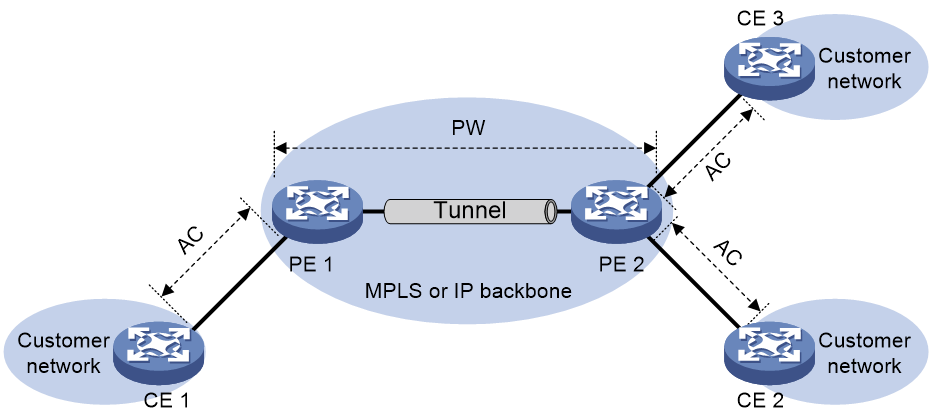
As shown in Figure 1, an EVPN VPLS network contains the following devices:
· Customer edge (CE)—Customer device directly connected to the service provider network.
· Provider edge (PE)—Service provider device connected to CEs. PEs provide access to the EVPN VPLS network and forward traffic between customer network sites by using public tunnels.
A PE uses ACs, PWs, tunnels, and VSIs to provide EVPN VPLS services.
· Attachment circuit (AC)—A physical or virtual link between a CE and a PE.
· Pseudowire (PW)—A pair of unidirectional virtual connections in opposite directions between two PEs.
· Public tunnel—A connection that carries one or more PWs across the MPLS or IP backbone. A public tunnel can be an LSP, GRE, or MPLS TE tunnel.
· Virtual Switch Instance (VSI)—A virtual switch instance provides Layer 2 switching services for a VPLS instance (EVPN instance) on a PE. A VSI acts as a virtual switch that has all the functions of a conventional Ethernet switch, including source MAC address learning, MAC address aging, and flooding. VPLS uses VSIs to forward Layer 2 data packets in EVPN instances.
Neighbor auto-discovery and PW establishment
In an EVPN VPLS network, PEs discover neighbors and establish PWs by using the following procedure:
1. The PEs assign two PW labels to each VSI for forwarding known unicast, broadcast, unknown unicast, and unknown multicast (BUM) packets.
2. Each PE advertises the PW labels to remote PEs as follows:
¡ Advertises the PW labels used for forwarding known unicast packets through MAC/IP prefix advertisement routes or Ethernet auto-discovery routes.
¡ Advertises the PW labels used for forwarding BUM traffic through IMET routes.
Those routes carry route targets.
3. Each PE matches the route targets in a received MAC/IP prefix advertisement route, Ethernet auto-discovery route, or IMET route with the import targets of the EVPN instance. If the route targets match the import targets, the PE establishes a unidirectional virtual connection based on the PE address and PW label information carried in the route.
PW establishment is finished when two virtual connections in opposite directions are established between two PEs.
MAC address learning, aging, and withdrawal
Source MAC address learning
A PE uses the MAC address table of a VSI to forward Layer 2 unicast traffic for that VSI.
A PE learns source MAC addresses in the following ways:
· Local MAC address learning—When the PE receives a frame from a local CE, it first identifies the VSI of the frame. Then, the PE adds the source MAC address of the frame (the MAC address of the local CE) to the MAC address table of the VSI. The output interface of the MAC address entry is the AC that receives the frame.
· Remote MAC address learning—A PE advertises the MAC addresses of local CEs to remote PEs through BGP EVPN MAC/IP advertisement routes. When a remote PE receives the routes, it adds the received MAC addresses to the MAC address table of the corresponding VSI. The output interface is the PW.
MAC address aging
· Local MAC address aging—The MAC address table uses an aging timer for each dynamic MAC address entry. If no packet is received from a MAC address before the aging timer expires, VPLS deletes the MAC address.
· Remote MAC address aging—Remote MAC addresses advertised through MAC/IP advertisement routes are not removed from the MAC address table until routes to withdraw the MAC addresses are received.
MAC address withdrawal
When an AC goes down, the PE deletes MAC addresses on the AC. Then it sends an LDP address withdrawal message to notify all other PEs in the EVPN instance to delete those MAC addresses.
Traffic forwarding and flooding
Unicast traffic forwarding
After a PE receives a unicast packet with a known destination MAC address from an AC, the PE searches the MAC address table of the VSI bound to the AC for packet forwarding.
· If the output interface in the entry is a PW, the PE inserts the PW label of the PW to the packet, and adds the public tunnel header to the packet. It then forwards the packet to the remote PE over the PW. If the public tunnel is an LSP or MPLS TE tunnel, each packet on the PW contains two labels. The inner label is the PW label, which identifies the PW and ensures that the packet is forwarded to the correct VSI. The outer label is the public LSP or MPLS TE tunnel label, which ensures that the packet is correctly forwarded to the remote PE.
· If the output interface in the entry is a local interface, the PE directly forwards the packet to the local interface.
After a PE receives a unicast packet with a known destination MAC address from a PW, the PE searches the MAC address table of the VSI bound to the PW for packet forwarding. The PE forwards the packet through the output interface in the matching MAC address entry.
Flooding
When a PE receives flood traffic from an AC in a VSI, it will flood the traffic to the following interfaces:
· All ACs in the VSI except for the incoming AC.
· All PWs associated with the VSI.
When a PE receives flood traffic from a PW, it will flood the traffic to all ACs in the VSI bound to the PW.
Full mesh and split horizon
A Layer 2 network requires a loop prevention protocol such as STP to avoid loops. However, a loop prevention protocol on PEs brings management and maintenance difficulties. Therefore, EVPN VPLS uses the following methods to prevent loops:
· Full mesh—Every two PEs in an EVPN instance must establish PWs. The PWs form a full mesh among PEs in the EVPN instance.
· Split horizon—A PE does not forward packets received from a PW to any other PWs in the same VSI but only forwards those packets to ACs.
EVPN VPLS multihoming
About EVPN VPLS multihoming
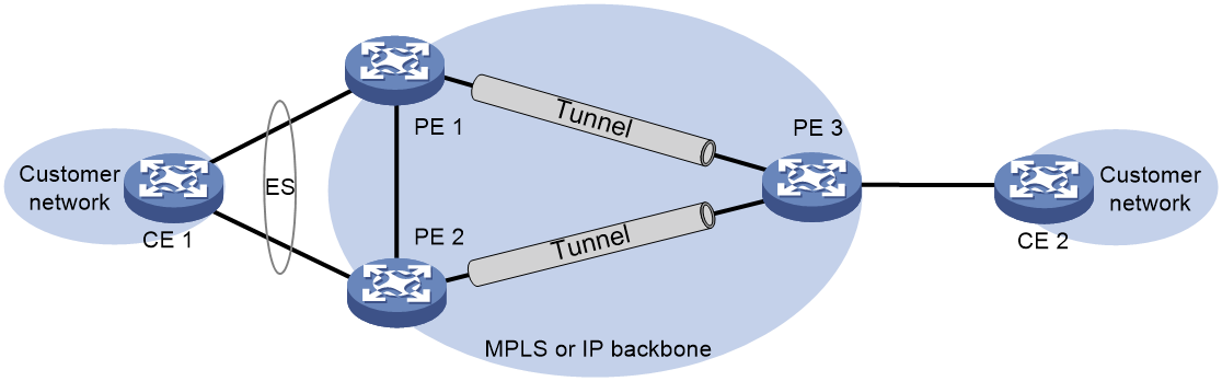
As shown in Figure 2, EVPN VPLS supports deploying multiple PEs at a site for redundancy and high availability. On the redundant PEs, Ethernet links connected to the site form an ES that is uniquely identified by an ESI. EVPN VPLS supports only dualhoming.
Figure 2 EVPN VPLS multihoming
DF election
To prevent redundant PEs from sending duplicate flood traffic to a multihomed site, a designated forwarder (DF) is elected from the PEs to forward flood traffic to the local site. PEs that fail the election are assigned the backup designated forwarder (BDF) role. BDFs do not forward flood traffic to the local site.
DF election can be performed by using a VLAN tag-based algorithm or preference-based algorithm.
· VLAN tag-based DF election
PEs select a DF for each AC based on the VLAN tag and PE IP address as follows:
a. Arrange source IP addresses in Ethernet segment routes with the same ESI in ascending order and assign a sequence number to each IP address, starting from 0.
b. Divide the lowest VLAN ID permitted on an AC by the number of the redundant PEs, and match the reminder to the sequence numbers of IP addresses.
c. Assign the DF role to the PE that uses the IP address with the matching sequence number.
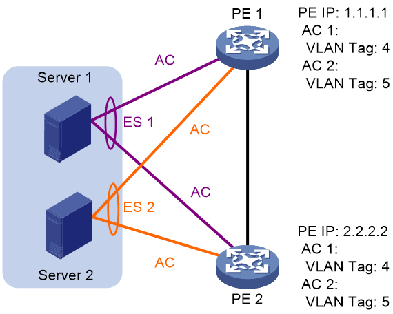
The following uses PE 1 and PE 2 in Figure 4 as an example to explain the DF election procedure:
a. PE 1 and PE 2 send Ethernet segment routes to each other.
b. The PEs assign sequence numbers 0 and 1 to IP addresses 1.1.1.1 and 2.2.2.2 in the Ethernet segment routes, respectively.
c. The PEs divide 4 (the lowest VLAN ID permitted by the ACs) by 2 (the number of redundant PEs), and match the reminder 0 to the sequence numbers of the IP addresses.
d. The DF role is assigned to PE 1 at 1.1.1.1.
Figure 4 VLAN tag-based DF election
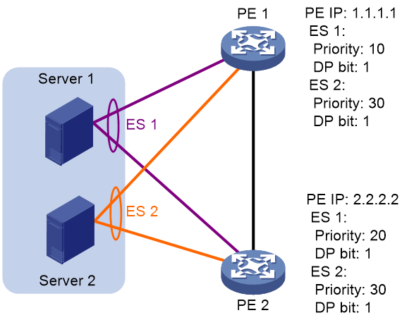
· Preference-based DF election
PEs select a DF for each ES based on the DF election preference, the Don't Preempt Me (DP) bit in Ethernet segment routes, and PE IP address. The DP bit can be set to one of the following values:
¡ 1—Non-revertive mode is enabled for preference-based DF election (DF preemption is disabled). A DF retains its role when a new DF is elected.
¡ 0—Non-revertive mode is disabled for preference-based DF election (DF preemption is enabled).
Preference-based DF election uses the following rules to select a DF for an ES:
a. The PE with higher preference becomes the DF.
b. If two PEs have the same preference, the PE with the DP bit set to 1 becomes the DF.
c. If both of the PEs have the DP bit set to 1, the PE with a lower IP address becomes the DF.
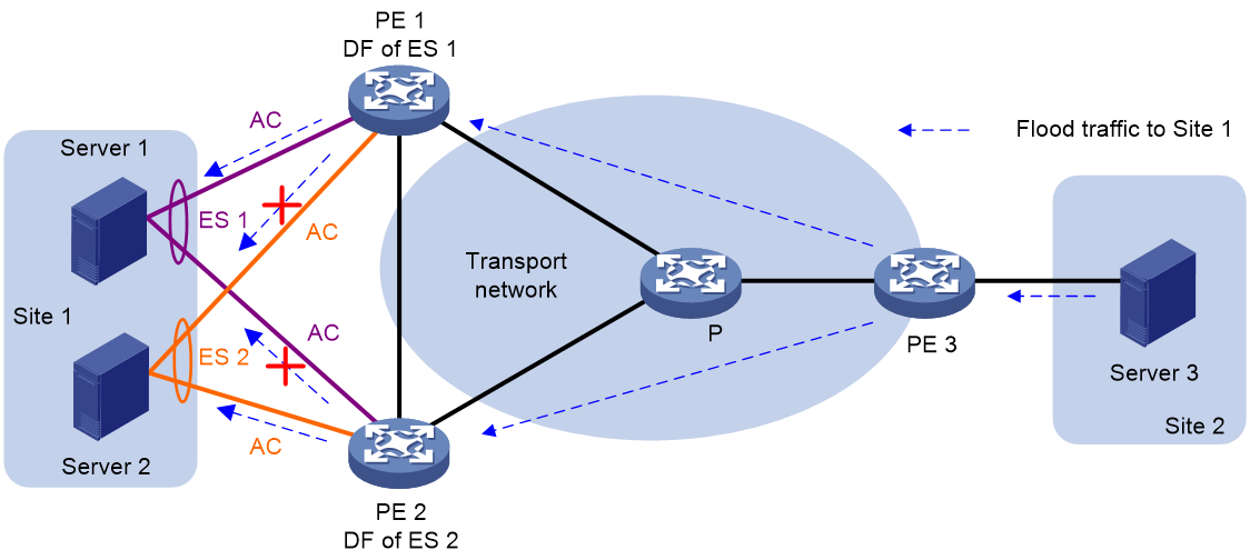
As shown in Figure 5, PE 2 is the DF for ES 1, and PE 1 is the DF for ES 2.
Figure 5 Preference-based DF election
Redundancy mode
The device supports single-active redundancy mode and all-active redundancy mode of EVPN VPLS multihoming.
· Single-active mode—This mode allows one of the redundant PEs to forward traffic. When the primary PE becomes unavailable because of device failure or link failure, traffic is switched to the secondary PE for forwarding.
· All-active mode—This mode allows all redundant PEs to a multihomed site to load share unicast traffic.
IP aliasing
In all-active redundancy mode, all redundant PEs of an ES advertise the ES to remote PEs through MP-BGP. IP aliasing allows a remote PE to add the IP addresses of all the redundant PEs as the next hops for the MAC or ARP information received from one of these PEs. This mechanism creates ECMP routes between the remote PE and the redundant PEs.
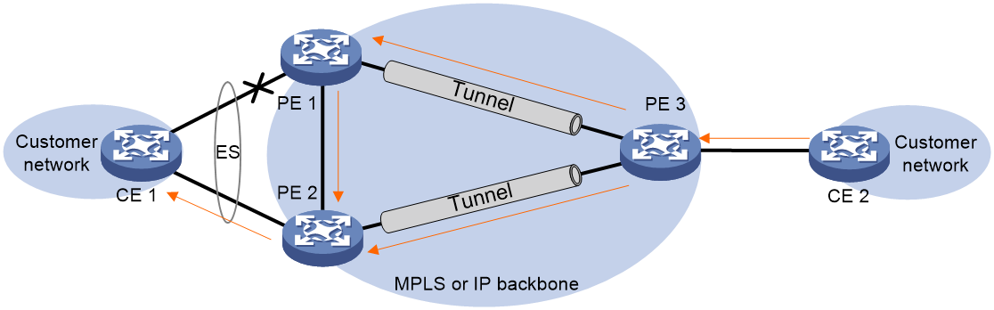
Local FRR for EVPN VPLS
As shown in Figure 6, CE 1 is dualhomed to PE 1 and PE 2, and PE 1 is the DF. When the AC on PE 1 fails, PE 1 deletes the corresponding MAC address entries and advertises the local unreachable event to PE 2 and remote PEs (PE 3 in this example). Then, the remote PEs will switch traffic destined for CE 1 to the tunnels to PE 2. This process takes some time. PE 1 might receive packets destined for CE 1 before the remote PEs are notified of the unreachable event and perform link switchover. In this situation, PE 1 drops the packets, because the AC's MAC address entries have been deleted. To resolve this issue, enable local FRR on PE 1. If an AC fails, PE 1 changes the output interface of the AC's MAC address entries to the index of the PW between PE 1 and PE 2. When receiving packets from remote PEs after its AC fails, PE 1 forwards the packets to PE 2 over the PW to prevent traffic loss.
Figure 6 Local FRR network diagram
ARP flood suppression
ARP flood suppression reduces ARP request broadcasts by enabling a PE to reply to ARP requests on behalf of VMs.
As shown in Figure 7, this feature snoops ARP requests, ARP responses, and BGP EVPN routes to populate the ARP flood suppression table with local and remote MAC addresses. If an ARP request has a matching entry, the PE replies to the request on behalf of the VM. If no match is found, the PE floods the request to both local and remote sites.
Figure 7 ARP flood suppression
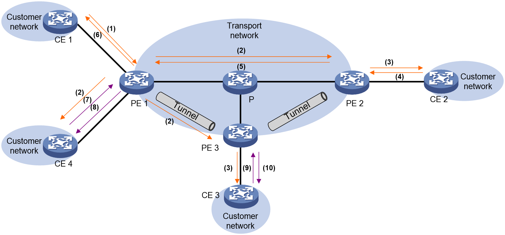
ARP flood suppression uses the following workflow:
1. CE1 sends an ARP request to obtain the MAC address of CE 2.
2. PE 1 creates a suppression entry for CE 1, floods the ARP request to local CEs and remote PEs (PE 2 and PE 3) in the VSI, and sends the suppression entry to PE 2 and PE 3 through BGP EVPN. Unicast-mode flooding is used to illustrate the workflow.
3. PE 2 and PE 3 de-encapsulate the ARP request and broadcast the request to local CEs in the VSI.
4. CE 2 sends an ARP reply after it receives the ARP request.
5. PE 2 creates a suppression entry for CE 2, forwards the ARP reply to PE 1, and sends the suppression entry to PE 1 and PE 3 through BGP EVPN.
6. PE 1 de-encapsulates the ARP reply and forwards the ARP reply to CE 1.
7. CE 4 sends an ARP request to obtain the MAC address of CE 1.
8. PE 1 creates a suppression entry for CE 4 and replies to the ARP request.
9. CE 3 sends an ARP request to obtain the MAC address of CE 1.
10. PE 3 creates a suppression entry for CE 3 and replies to the ARP request.
Control word
The control word field is between the MPLS label stack and the Layer 2 data. It carries control information for the Layer 2 frame, for example, the sequence number.
The control word feature has the following functions:
· Avoids fragment disorder. In multipath forwarding, fragments received might be disordered. The control word feature reorders the fragments according to the sequence number carried in the control word field.
· Identifies the original payload length for packets that include padding.
The control word field is optional for EVPN VPLS. You can configure whether to carry the control word field in packets sent on PWs. If you enable the control word feature on PEs at both ends of a PW, packets transmitted on the PW carry the control word field. Otherwise, the packets do not carry the control word field.
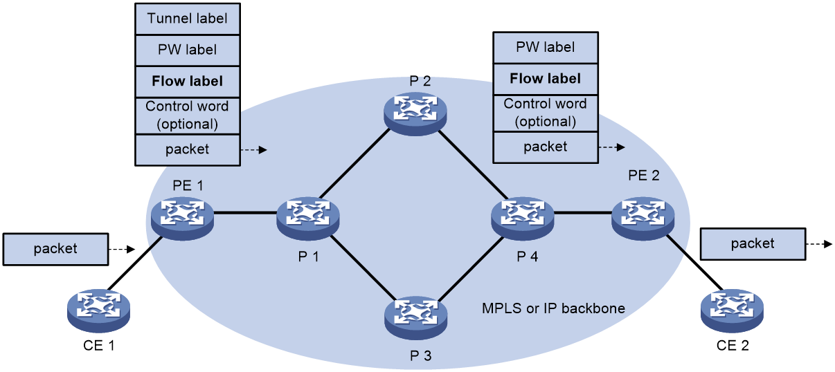
L2VPN flow label
Packets carrying different types of traffic might be transmitted through the same PW and encapsulated with the same PW label. The P devices forward the traffic flows of a PW over the same path even if Equal Cost Multiple Paths (ECMPs) exist.
The L2VPN flow label feature can enable a P device to perform load sharing on packets based on the flow types.
After you configure this feature, the P and PE devices process packets as follows:
· When the ingress PE encapsulates a packet, it adds a flow label before it adds a PW label, as shown in Figure 8.
The ingress PE adds different flow labels for packets of different traffic types.
· The P devices perform load sharing on packets based on the flow labels.
· The egress PE removes both the PW and flow labels from a packet before forwarding the packet.
Figure 8 L2VPN flow label feature
You can enable the flow label sending, receiving, or both sending and receiving capabilities on a PE.
· The sending capability enables a PE to send packets with flow labels. The PE adds a flow label before it adds a PW label to a packet during encapsulation.
· The receiving capability enables a PE to identify the flow label in a received packet and removes the flow label before forwarding the packet.
For two PEs to successfully negotiate the flow label capabilities, make sure one end has the sending capability and the other end has the receiving capability.
For EVPN VPLS, you must manually configure flow label capabilities for the local and remote PEs.
MAC mobility
MAC mobility refers to the movement of a VM or host from one ES to another. The source PE is unaware of the MAC move event. To notify other PEs of the change, the destination PE advertises a MAC/IP advertisement route for the MAC address. The source PE withdraws the old route for the MAC address after receiving the new route. The MAC/IP advertisement route has a sequence number that increases when the MAC address moves. The sequence number identifies the most recent move if the MAC address moves multiple times.
EVPN E-tree
About EVPN E-tree
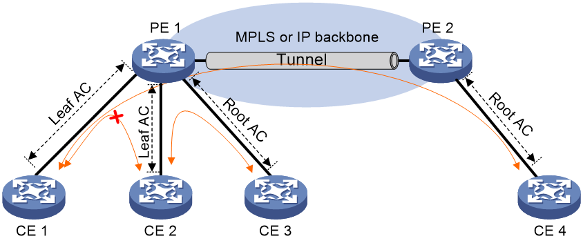
In an EVPN VPLS network, EVPN E-tree isolates unicast and flood traffic (broadcast, multicast, and unknown unicast) of ACs in the same EVPN instance based on the AC roles. With EVPN E-tree, the device isolates unicast and flood traffic of ACs in the same EVPN instance as follows:
· Leaf ACs can access root ACs.
· Leaf ACs cannot access each other.
· Root ACs can access each other and access leaf ACs.
Figure 9 EVPN E-tree network diagram
Local traffic isolation
EVPN E-tree isolates traffic between local ACs on a PE as follows:
· When the PE receives packets from a leaf AC on a VSI, it forwards the packets only to root ACs on the VSI.
· When the PE receives packets from a root AC on a VSI, it forwards the packets to all local ACs on the VSI except the incoming AC.
Remote known unicast traffic isolation
With EVPN E-tree, PEs perform MAC address learning for hosts attached to leaf ACs as follows:
1. When a PE receives a packet from a leaf AC, it learns the source MAC address of the packet and adds the Leaf flag to the MAC address.
2. The PE advertises the MAC address to the remote PE in a MAC/IP advertisement route. The route carries the E-tree extended community attribute that contains the Leaf flag.
3. The remote PE adds the MAC address that carries the Leaf flag to the MAC address table.
When one PE receives a packet destined for a host on another PE from a local AC, it searches the MAC address table for the destination MAC address. If the entry of the destination MAC address has the Leaf flag and the packet is also from a leaf AC, the PE discards the packet. In other situations, the PE forwards the packet.
Remote flood traffic isolation
With EVPN E-tree, a PE assigns a Leaf label to the leaf ACs of each VSI. The PE adds the Leaf label to the E-tree extended community attribute in Ethernet auto-discovery routes and advertises the routes to remote PEs.
EVPN E-tree isolates flood traffic from one PE to another PE as follows:
1. When a PE receives a flood packet from a leaf AC on a VSI, it adds the Leaf label of that VSI to the packet, and then adds the private network label and public network label to the packet. After that, the PE forwards the packet to the remote PE.
2. The remote PE removes the private network label and public network label and finds the Leaf label. Then, the PE forwards the packet only to local root ACs on the same VSI.
LDP or static PW ACs for EVPN PWs
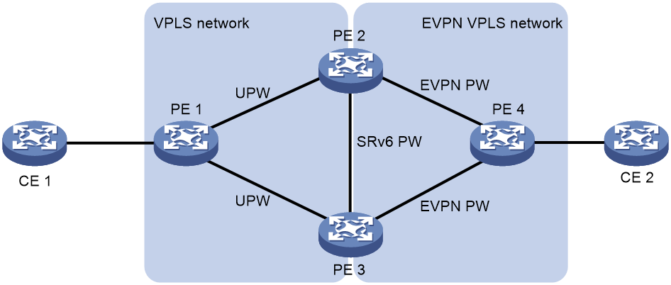
This feature ensures that a traditional VPLS network and an EVPN VPLS network can communicate with each other. The LDP or static PWs in the VPLS network are configured as ACs to the EVPN VPLS network. These ACs are referred to as UPWs in the EVPN VPLS network. Packets can be forwarded between EVPN PWs and UPWs, so the VPLS and EVPN VPLS networks can communicate with each other.
With this feature, an LDP or static PW can be single-homed to an EVPN PW or two LDP or static PWs can be dual-homed to two EVPN PWs.
As shown in Figure 10, in the VPLS network, PE 1 is connected to PE 2 and PE 3 through LDP or static PWs. One of the PWs is the primary PW and the other PW is the backup PW. The PWs are UPWs. In the EVPN VPLS network, PE 4 is connected to PE 2 and PE 3 through EVPN PWs. The UPWs in the VPLS network act as ACs for the EVPN VPLS network. When PE 2 or PE 3 receives packets from the UPWs, it decapsulates MPLS encapsulation from the packets and looks up the MAC address table for a matching EVPN PW. Then, the PE adds MPLS encapsulation to the packets based on the EVPN PW and forwards the packets to PE 4. When PE 2 or PE 3 receives packets from an EVPN PW, it uses the same procedure to process the packets.
Figure 10 LDP or static PW ACs for EVPN PWs
Intercommunication between EVPN VXLAN and EVPN VPLS networks
Figure 11 shows a typical application scenario for intercommunication between EVPN VXLAN and EVPN VPLS networks. Two EVPN VXLAN networks are connected through an EVPN VPLS network. GW 1, GW 2, GW 3, and GW 4 are boundary devices of the EVPN VXLAN and EVPN VPLS networks. They reoriginate the MAC/IP advertisement routes generated in one network and advertise the routes to another network. Route advertisement across the EVPN VXLAN and EVPN VPLS networks enables intercommunication between the EVPN VXLAN and EVPN VPLS networks.
Figure 11 Application scenario for intercommunication between EVPN VXLAN and EVPN VPLS networks
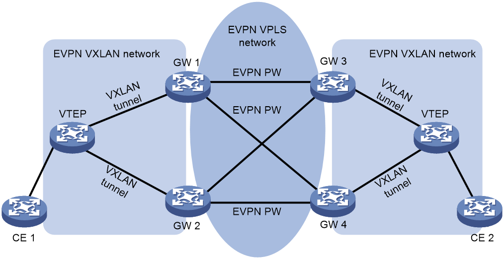
As shown in Figure 11, GWs handle received MAC/IP advertisement routes as follows:
· When a GW receives a MAC/IP advertisement route from an EVPN VXLAN network, it reoriginates the route and advertises the route to the EVPN VPLS network. When the GW reoriginates the route, it performs the following operations:
a. Assigns and adds an MPLS label to the route.
b. Changes the encapsulation type of the route to MPLS encapsulation.
c. Changes the RD and route targets of the route.
· When a GW receives a MAC/IP advertisement route from the EVPN VPLS network, it reoriginates the route and advertises the route to the connected EVPN VXLAN network. When the GW reoriginates the route, it performs the following operations:
a. Looks up the VXLAN ID matching the route and adds the VXLAN ID to the route.
b. Changes the encapsulation type of the route to VXLAN encapsulation.
c. Changes the RD and route targets of the route.
After the GWs finish MAC address learning through MAC/IP advertisement routes, they add VXLAN or MPLS encapsulation to received packets according to the learned MAC address entries. Then, they forward the packets to an EVPN VXLAN network or the EVPN VPLS network.
For more information about configuring intercommunication between EVPN VXLAN and EVPN VPLS networks, see "Configuring EVPN VXLAN."
EVPN VPLS tasks at a glance
To configure EVPN VPLS, perform the following tasks:
b. (Optional.) Configure VSI parameters
2. Configuring an EVPN instance
¡ Mapping a Layer 3 interface to a VSI
¡ Mapping an Ethernet service instance to a VSI
4. Configuring BGP to advertise BGP EVPN routes
a. Enabling BGP to advertise BGP EVPN routes
b. Enabling advertisement of MPLS-encapsulated BGP EVPN routes
c. (Optional.) Configuring BGP EVPN route attributes
d. (Optional.) Configuring route advertisement and optimal route selection for BGP EVPN routes
e. (Optional.) Configuring BGP route reflection settings
f. (Optional.) Configuring BGP EVPN route filtering
g. (Optional.) Advertising BGP RPKI validation state to a peer or peer group
h. (Optional.) Configuring BGP soft-reset by saving all route updates
i. (Optional.) Maintaining BGP sessions
5. (Optional.) Configuring a PW class
6. (Optional.) Configuring EVPN VPLS multihoming
b. (Optional.) Configuring the DF election algorithm
c. (Optional.) Setting the DF election delay
d. (Optional.) Setting the advertisement delay timer for Ethernet auto-discovery routes
e. (Optional.) Configuring local FRR for EVPN VPLS
f. (Optional.) Generating MAC address entries for received MAC/IP advertisement routes
g. (Optional.) Enabling VSIs to ignore the state of ACs
h. (Optional.) Disabling advertisement of EVPN multihoming routes
i. (Optional.) Ignoring the Ethernet tag on advertisement of Ethernet auto-discovery and MAC/IP advertisement routes
j. (Optional.) Configuring the device to advertise only MAC/IP advertisement routes that contain non-all-zero MAC addresses
k. (Optional.) Enabling the device to monitor the BGP peer status of another local edge device
7. (Optional.) Managing MAC address entries and ARP learning
¡ Disabling MAC address advertisement
¡ Enabling MAC mobility event suppression
¡ Disabling learning of MAC addresses from ARP or ND information
¡ Configuring the AC source MAC check feature
¡ Disabling ARP information advertisement
8. (Optional.) Enabling EVPN E-tree
9. (Optional.) Configuring LDP or static PWs as ACs for EVPN PWs
10. (Optional.) Optimizing and maintaining an EVPN VPLS network:
¡ Confining floods to the local site
¡ Enabling ARP flood suppression
¡ Setting the maximum number of MAC addresses that an AC can learn
¡ Enabling packet statistics for an AC
¡ Enabling bandwidth-based load sharing
¡ Enabling SNMP notifications for L2VPN PW
¡ Enabling SNMP notifications for EVPN
¡ Testing the connectivity of an EVPN PW
Restrictions and guidelines: EVPN VPLS configuration
In standard system operating mode, only the following cards support EVPN VPLS:
|
Card category |
Cards |
|
CEPC |
CEPC-CQ8L, CEPC-CQ8LA, CEPC-CQ8L1A, CEPC-CQ16L1 |
|
CSPEX |
CSPEX-1802X, CSPEX-1802XA, CSPEX-2612XA, CSPEX-1812X-E, CSPEX-2304X-G, CSPEX-1502XA |
|
SPE |
RX-SPE200-E |
In SDN-WAN system operating mode, only the following cards support EVPN VPLS:
|
Card category |
Cards |
|
CEPC |
CEPC-XP4LX, CEPC-XP24LX, CEPC-XP48RX, CEPC-CP4RX, CEPC-CP4RXA, CEPC-CP4RX-L, CEPC-CQ8L, CEPC-CQ8LA, CEPC-CQ8L1A, CEPC-CQ16L1 |
|
CSPEX |
CSPEX-1304X, CSPEX-1404X, CSPEX-1502X, CSPEX-1504X, CSPEX-1504XA, CSPEX-1602X, CSPEX-1602XA, CSPEX-1804X, CSPEX-1512X, CSPEX-1612X, CSPEX-1812X, CSPEX-1802X, CSPEX-1802XA, CSPEX-2612XA, CSPEX-1812X-E CSPEX-2304X-G, CSPEX-1502XA |
|
SPE |
RX-SPE200, RX-SPE200-E |
EVPN VPLS is mutually exclusive with EVPN-DCI dualhoming. Do not use the evpn edge group command in an EVPN VPLS network.
E-Tree is not supported if CFD or NQA is configured. For more information about CFD, see High Availability Configuration Guide. For more information about NQA, see Network Management and Monitoring Configuration Guide.
For more information about EVPN-DCI dualhoming, see "Configuring EVPN-DCI."
Configuring a VSI
Creating a VSI
1. Enter system view.
system-view
2. Enable L2VPN.
l2vpn enable
By default, L2VPN is disabled.
3. Create a VSI and enter VSI view.
vsi vsi-name
4. Bring up the VSI.
undo shutdown
By default, a VSI is not administratively down.
Configure VSI parameters
1. Enter system view.
system-view
2. Enter VSI view.
vsi vsi-name
3. Configure a VSI description.
description text
By default, a VSI does not have a description.
4. Set the MTU of the VSI.
mtu mtu
The default MTU for a VSI is 1500 bytes.
5. Set the maximum bandwidth for known unicast traffic of the VSI.
bandwidth bandwidth
By default, the maximum bandwidth is not limited for known unicast traffic of a VSI.
6. Set the broadcast, multicast, or unknown unicast bandwidth restraints of the VSI.
restrain { broadcast | multicast | unknown-unicast } bandwidth
By default, the broadcast, multicast, and unknown unicast bandwidth restraints of a VSI are 5120 kbps.
7. Configure MAC address learning features for the VSI:
a. Enable MAC address learning for the VSI.
mac-learning enable
By default, MAC address learning is enabled for a VSI.
b. (Optional.) Enable the VSI to drop source-unknown unicast frames if the MAC address table is full.
mac-table limit drop-unknown
By default, the VSI forwards source-unknown unicast frames without learning the source MAC address if the MAC address table is full.
Configuring an EVPN instance
About EVPN instance configuration
The BGP EVPN routes advertised by a PE carry the RD and route targets configured for the EVPN instance of the routes.
Use one of the following methods to create an EVPN instance:
· Create an EVPN instance in system view—You can bind an EVPN instance created in system view to multiple VSIs to simplify configuration.
· Create an EVPN instance on a VSI—An EVPN instance created in VSI view is automatically bound with the VSI.
In EVPN instance view and VSI EVPN instance view, you can configure routing policies to filer the routes redistributed from BGP EVPN to an EVPN instance and vice versa.
Restrictions and guidelines for EVPN instance configuration
If you have created an EVPN instance in VSI view for a VSI, you cannot bind the VSI to an EVPN instance created in system view. If you have bound a VSI to an EVPN instance created in system view, you cannot create an EVPN instance in VSI view for the VSI.
Configuring an EVPN instance created in system view
1. Enter system view.
system-view
2. Create an EVPN instance and enter its view.
evpn instance instance-name
3. Configure an RD for the EVPN instance.
route-distinguisher route-distinguisher
By default, no RD is configured for an EVPN instance.
4. Configure route targets for the EVPN instance.
vpn-target vpn-target&<1-8> [ both | export-extcommunity | import-extcommunity ]
By default, an EVPN instance does not have route targets.
|
Parameter |
Description |
|
export-extcommunity |
Do not specify the same export targets for different EVPN instances. Do not specify the same export targets for the EVPN instances created in different views (system view, VSI view, VPN instance view, public instance view, and cross-connect group view). As a best practice, the export targets configured for the following objects do not match the import targets configured for the EVPN instances created in cross-connect group view: · VPN instances. · The public instance. · EVPN instances created in system view, VSI view, VPN instance view, and public instance view. |
|
import-extcommunity |
As a best practice, the import targets configured for the following objects do not match the export targets configured for the EVPN instances created in cross-connect group view: · VPN instances. · The public instance. · EVPN instances created in system view, VSI view, VPN instance view, and public instance view. |
5. (Optional.) Apply a PW class to the EVPN instance.
pw-class class-name
By default, no PW class is applied to an EVPN instance.
The PW class applies to all PWs in the EVPN instance.
6. (Optional.) Apply a tunnel policy to the EVPN instance.
tunnel-policy tunnel-policy-name
By default, no tunnel policy is applied to an EVPN instance.
7. (Optional.) Apply an export routing policy to the EVPN instance.
export route-policy route-policy
By default, no export routing policy is applied to an EVPN instance. The EVPN instance does not filter advertised routes.
8. (Optional.) Apply an import routing policy to the EVPN instance.
import route-policy route-policy
By default, no import routing policy is applied to an EVPN instance. The EVPN instance accepts a route when the export route targets of the route match local import route targets.
9. Return to system view.
quit
10. Enter VSI view.
vsi vsi-name
11. Bind the VSI to the EVPN instance.
evpn encapsulation mpls binding instance instance-name vsi-tag tag-id
By default, a VSI is not bound to an EVPN instance created in system view.
You can bind a VSI to one or two EVPN instances. If you bind a VSI to two EVPN instances, the encapsulation type must be MPLS for one EVPN instance and VXLAN for the other EVPN instance.
Configuring an EVPN instance created in VSI view
1. Enter system view.
system-view
2. Enter VSI view.
vsi vsi-name
3. Create an EVPN instance and enter VSI EVPN instance view.
evpn encapsulation mpls
4. Configure an RD for the EVPN instance.
route-distinguisher route-distinguisher
By default, no RD is configured for an EVPN instance.
5. Configure route targets for the EVPN instance.
vpn-target { vpn-target&<1-8> | auto } [ both | export-extcommunity | import-extcommunity ]
By default, an EVPN instance does not have route targets.
|
Parameter |
Description |
|
export-extcommunity |
Do not specify the same export targets for the EVPN instances of different VSIs. Do not specify the same export targets for the EVPN instances created in different views (system view, VSI view, VPN instance view, public instance view, and cross-connect group view). As a best practice, the export targets configured for the following objects do not match the import targets configured for the EVPN instances created in cross-connect group view: · VPN instances. · The public instance. · EVPN instances created in system view, VSI view, VPN instance view, and public instance view. |
|
import-extcommunity |
As a best practice, the import targets configured for the following objects do not match the export targets configured for the EVPN instances created in cross-connect group view: · VPN instances. · The public instance. · EVPN instances created in system view, VSI view, VPN instance view, and public instance view. |
6. (Optional.) Apply a PW class to the EVPN instance.
pw-class class-name
By default, no PW class is applied to an EVPN instance.
The specified PW class applies to all PWs in the EVPN instance.
7. (Optional.) Apply a tunnel policy to the EVPN instance.
tunnel-policy tunnel-policy-name
By default, no tunnel policy is applied to an EVPN instance.
8. (Optional.) Apply an export routing policy to the EVPN instance.
export route-policy route-policy
By default, no export routing policy is applied to an EVPN instance. The EVPN instance does not filter advertised routes.
9. (Optional.) Apply an import routing policy to the EVPN instance.
import route-policy route-policy
By default, no import routing policy is applied to an EVPN instance. The EVPN instance accepts a route when the export route targets of the route match local import route targets.
Mapping ACs to a VSI
Mapping a Layer 3 interface to a VSI
About this task
To assign the customer traffic on a Layer 3 interface to a VSI, map that interface to the VSI. The VSI uses its MAC address table to forward the customer traffic.
For more information about the commands in this task, see VPLS in MPLS Command Reference.
Procedure
1. Enter system view.
system-view
2. Enter Layer 3 interface view.
interface interface-type interface-number
3. Map the Layer 3 interface to a VSI.
xconnect vsi vsi-name [ access-mode { ethernet | vlan } ] [ track track-entry-number&<1-3> ]
By default, a Layer 3 interface is not mapped to a VSI.
Mapping an Ethernet service instance to a VSI
About this task
An Ethernet service instance matches a list of VLANs on a site-facing interface by using a frame match criterion. The frame match criterion specifies the characteristics of traffic from the VLANs, such as tagging status and VLAN IDs. The PE assigns traffic from the VLANs to a VSI by mapping the Ethernet service instance to the VSI. The VSI performs Layer 2 forwarding for the VLANs based on its MAC address table.
For more information about the commands in this task, see VPLS in MPLS Command Reference.
Restrictions and guidelines
An Ethernet service instance can contain only one match criterion. To change the match criterion, you must remove the original criterion first. When you remove the match criterion in an Ethernet service instance, the mapping between the service instance and the VSI is removed automatically.
Procedure
1. Enter system view.
system-view
2. Enter interface view.
¡ Enter Layer 2 Ethernet interface view.
interface interface-type interface-number
¡ Enter Layer 2 aggregate interface view.
interface bridge-aggregation interface-number
3. Create an Ethernet service instance and enter Ethernet service instance view.
service-instance instance-id
4. Match frames with the specified outer VLAN tag.
encapsulation s-vid vlan-id
By default, an Ethernet service instance does not contain a frame match criterion.
5. Map the Ethernet service instance to a VSI.
xconnect vsi vsi-name [ access-mode { ethernet | vlan } ] [ track track-entry-number&<1-3> ]
By default, an Ethernet service instance is not mapped to a VSI.
Configuring BGP to advertise BGP EVPN routes
Restrictions and guidelines for BGP EVPN route advertisement
For more information about BGP commands in this task, see Layer 3—IP Routing Command Reference.
Enabling BGP to advertise BGP EVPN routes
1. Enter system view.
system-view
2. Configure a global router ID.
router id router-id
By default, no global router ID is configured.
3. Enable a BGP instance and enter BGP instance view.
bgp as-number [ instance instance-name ]
By default, BGP is disabled and no BGP instances exist.
4. Specify remote PEs as BGP peers.
peer { group-name | ipv4-address [ mask-length ] } as-number as-number
5. Create the BGP EVPN address family and enter BGP EVPN address family view.
address-family l2vpn evpn
6. Enable BGP to exchange BGP EVPN routes with a peer or peer group.
peer { group-name | ipv4-address [ mask-length ] } enable
By default, BGP does not exchange BGP EVPN routes with peers.
Enabling advertisement of MPLS-encapsulated BGP EVPN routes
About this task
Perform this task on PEs for them to establish PWs.
Procedure
1. Enter system view.
system-view
2. Enter BGP instance view.
bgp as-number [ instance instance-name ]
3. Enter BGP EVPN address family view.
address-family l2vpn evpn
4. Enable MPLS encapsulation for the BGP EVPN routes advertised to a peer or peer group.
peer { group name | ipv4-address [ mask-length ] | ipv6-address [ prefix-length ] } advertise encap-type mpls
By default, BGP EVPN routes use VXLAN encapsulation.
Configuring BGP EVPN route attributes
1. Enter system view.
system-view
2. Enter BGP instance view.
bgp as-number [ instance instance-name ]
3. Enter BGP EVPN address family view.
address-family l2vpn evpn
4. Set a preferred value for routes received from a peer or peer group.
peer { group-name | ipv4-address [ mask-length ] | ipv6-address [ prefix-length ] } preferred-value value
By default, the preferred value is 0 for routes received from a peer or peer group.
5. Permit the local AS number to appear in routes from a peer or peer group and set the number of appearances.
peer { group-name | ipv4-address [ mask-length ] } allow-as-loop [ number ]
By default, the local AS number is not allowed in routes from peers.
6. Configure BGP to remove or replace private AS numbers with the local AS number in BGP updates sent to an EBGP peer or peer group.
peer { group-name | ipv4-address [ mask-length ] | ipv6-address [ prefix-length ] } public-as-only [ { force | limited } [ replace ] [ include-peer-as ] ]
peer { group-name | ipv4-address [ mask-length ] | ipv6-address [ prefix-length ] } public-as-only [ force [ include-peer-as ] ] keep-local-as
By default, BGP updates sent to an EBGP peer or peer group can carry both public and private AS numbers.
7. Disable the device from changing the next hop of routes advertised to an EBGP peer or peer group.
peer { group-name | ipv4-address [ mask-length ] } next-hop-invariable
By default, BGP sets the local device as the next hop for all routes advertised to an EBGP peer or peer group.
8. Advertise the COMMUNITY attribute or the Large community attribute to a peer or peer group.
¡ Advertise the COMMUNITY attribute to a peer or peer group.
peer { group-name | ipv4-address [ mask-length ] } advertise-community
By default, the COMMUNITY attribute is not advertised to a peer or peer group.
¡ Advertise the Large community attribute to a peer or peer group.
peer { group-name | ipv4-address [ mask-length ] } advertise-large-community
By default, the Large community attribute is not advertised to a peer or peer group.
9. Configure the SoO attribute for a peer or peer group.
peer { group-name | ipv4-address [ mask-length ] | ipv6-address [ prefix-length ] } soo site-of-origin
By default, no SoO attribute is configured for a peer or peer group.
10. Enable BGP to add the link bandwidth attribute to routes received from a peer or peer group.
peer { group-name | ipv4-address [ mask-length ] | ipv6-address [ prefix-length ] } bandwidth
By default, BGP does not add the link bandwidth attribute to routes received from a peer or peer group.
Configuring route advertisement and optimal route selection for BGP EVPN routes
1. Enter system view.
system-view
2. Enter BGP instance view.
bgp as-number [ instance instance-name ]
3. Enter BGP EVPN address family view.
address-family l2vpn evpn
4. Configure optimal route selection.
¡ Set a high priority for BGP routes learned from a peer or peer group during optimal route selection.
peer { group-name | ipv4-address [ mask-length ] | ipv6-address [ prefix-length ] } high-priority
By default, BGP does not prefer routes learned from any peer or peer groups during optimal route selection.
¡ Set the optimal route selection delay timer.
route-select delay delay-value
By default, the optimal route selection delay timer is 0 seconds, which means optimal route selection is not delayed.
5. Configure BGP route dampening:
¡ Configure EBGP route dampening.
dampening [ half-life-reachable half-life-unreachable reuse suppress ceiling | route-policy route-policy-name ] *
For more information about this command, see BGP commands in Layer 3—IP Routing Command Reference.
¡ Configure IBGP route dampening.
dampening ibgp [ half-life-reachable half-life-unreachable reuse suppress ceiling | route-policy route-policy-name ] *
For more information about this command, see MPLS L3VPN commands in MPLS Command Reference.
By default, BGP route dampening is not configured.
For more information about route dampening, see BGP configuration in Layer 3—IP Routing Configuration Guide.
6. Set the delay time for responding to recursive next hop changes.
nexthop recursive-lookup [ non-critical-event ] delay [ delay-value ]
By default, BGP responds to recursive next hop changes immediately.
7. Configure the BGP additional path feature.
¡ Configure the BGP additional path capabilities.
peer { group-name | ipv4-address [ mask-length ] } additional-paths { receive | send } *
By default, no BGP additional path capabilities are configured.
¡ Set the maximum number of Add-Path optimal routes that can be advertised to a peer or peer group.
peer { group-name | ipv4-address [ mask-length ] } advertise additional-paths best number
By default, a maximum number of one Add-Path optimal route can be advertised to a peer or peer group.
¡ Set the maximum number of Add-Path optimal routes that can be advertised to all peers.
additional-paths select-best best-number
By default, a maximum number of one Add-Path optimal route can be advertised to all peers.
8. Specify the maximum number of BGP EVPN routes that the local router can receive from a peer or peer group.
¡ Specify the maximum number of all types of BGP EVPN routes that the local router can receive from a peer or peer group.
peer { group-name | ipv4-address [ mask-length ] | ipv6-address [ prefix-length ] } route-limit prefix-number [ { alert-only| discard | reconnect reconnect-time } | percentage-value ] *
¡ Specify the maximum number of MAC/IP advertisement routes that the local router can receive from a peer or peer group.
peer { group-name | ipv4-address [ mask-length ] | ipv6-address [ prefix-length ] } macip-route-limit route-number [ { alert-only | discard | reconnect reconnect-time } | percentage-value ]
By default, the number of routes that the local router can receive from a peer or peer group is not limited.
In BGP EVPN address family view, the peer macip-route-limit command is mutually exclusive with the peer route-limit command for the same peer or peer group.
Configuring BGP route reflection settings
1. Enter system view.
system-view
2. Enter BGP instance view.
bgp as-number [ instance instance-name ]
3. Enter BGP EVPN address family view.
address-family l2vpn evpn
4. Configure the device as an RR and specify a peer or peer group as its client.
peer { group-name | ipv4-address [ mask-length ] } reflect-client
By default, no RR or client is configured.
5. (Optional.) Enable BGP EVPN route reflection between clients.
reflect between-clients
By default, BGP EVPN route reflection between clients is enabled.
6. (Optional.) Configure the cluster ID of the RR.
reflector cluster-id { cluster-id | ipv4-address }
By default, an RR uses its own router ID as the cluster ID.
7. (Optional.) Create a reflection policy for the RR to filter reflected BGP EVPN routes.
rr-filter { ext-comm-list-number | ext-comm-list-name }
By default, an RR does not filter reflected BGP EVPN routes.
8. (Optional.) Enable the RR to change the attributes of routes to be reflected.
reflect change-path-attribute
By default, the RR cannot change the attributes of routes to be reflected.
9. (Optional.) Add a peer or peer group to the nearby cluster.
peer { group-name | ipv4-address [ mask-length ] } reflect-nearby-group
By default, the nearby cluster does not have any peers or peer groups.
The RR does not change the next hop of routes reflected to peers or peer groups in the nearby cluster.
Configuring BGP EVPN route filtering
1. Enter system view.
system-view
2. Enter BGP instance view.
bgp as-number [ instance instance-name ]
3. Enter BGP EVPN address family view.
address-family l2vpn evpn
4. Enable route target filtering for BGP EVPN routes.
policy vpn-target
By default, route target filtering is enabled for BGP EVPN routes.
5. Apply a routing policy to routes received from or advertised to a peer or peer group.
peer { group-name | ipv4-address [ mask-length ] } route-policy route-policy-name { export | import }
By default, no routing policies are applied to routes received from or advertised to peers or peer groups.
6. Specify a routing policy as the existent policy to control BGP EVPN route advertisement.
peer { group-name | ipv4-address [ mask-length ] | ipv6-address [ prefix-length ] } advertise-policy advertise-policy-name exist-policy exist-policy-name
By default, no existent policy is specified to control BGP EVPN route advertisement.
7. Specify a routing policy as the nonexistent policy to control BGP EVPN route advertisement.
peer { group-name | ipv4-address [ mask-length ] | ipv6-address [ prefix-length ] } advertise-policy advertise-policy-name non-exist-policy non-exist-policy-name
By default, no nonexistent policy is specified to control BGP EVPN route advertisement.
8. Apply a Layer 2 ACL to filter routes advertised to or received from a peer or peer group.
peer { group-name | ipv4-address [ mask-length ] | ipv6-address [ prefix-length ] } filter-policy { mac-acl-number | name mac-acl-name } { export | import }
By default, no Layer 2 ACL is applied to filter routes advertised to or received from a peer or peer group.
To deny or permit a MAC/IP advertisement route with a specific MAC address, use the rule [ rule-id ] { deny | permit } dest-mac dest-address dest-mask command. Other rules configured in Layer 2 ACL view do not take effect on EVPN route filtering.
9. Apply an IPv4 prefix list to filter BGP EVPN routes advertised to or received from a peer or peer group.
peer { group-name | ipv4-address [ mask-length ] | ipv6-address [ prefix-length ] } prefix-list ipv4-prefix-list-name { export | import }
By default, no IPv4 prefix list is applied to filter BGP EVPN routes advertised to or received from a peer or peer group.
This command can filter only MAC/IP advertisement routes that contain host route information, and cannot filter other BGP EVPN routes.
Advertising BGP RPKI validation state to a peer or peer group
Restrictions and guidelines
BGP advertises the BGP RPKI validation state to a peer or peer group through the extended community attribute. For more information about BGP RPKI, see BGP in Layer 3—IP Routing Configuration Guide.
Procedure
1. Enter system view.
system-view
2. Enter BGP instance view.
bgp as-number [ instance instance-name ]
3. Enter BGP EVPN address family view.
address-family l2vpn evpn
4. Advertise the BGP RPKI validation state to a peer or peer group.
peer { group-name | ipv4-address [ mask-length ] | ipv6-address [ prefix-length ] } advertise origin-as-validation
By default, BGP does not advertise the BGP RPKI validation state to a peer or peer group.
Configuring BGP soft-reset by saving all route updates
About this task
Use this feature if the device does not support route refresh. This feature enables the device to save all route updates from the specified peer or peer group. When the route selection policy has changes, the device uses the new policy settings to filter routing information for BGP soft-reset.
Restrictions and guidelines
For more information about route refresh and BGP soft-reset, see BGP in Layer 3—IP Routing Configuration Guide.
Procedure
1. Enter system view.
system-view
2. Enter BGP instance view.
bgp as-number [ instance instance-name ]
3. Enter BGP EVPN address family view.
address-family l2vpn evpn
4. Save all route updates from a peer or peer group.
peer { group-name | ipv4-address [ mask-length ] | ipv6-address [ prefix-length ] } keep-all-routes
By default, route updates from peers and peer groups are not saved.
Maintaining BGP sessions
Perform the following tasks in user view:
· Reset BGP sessions of the BGP EVPN address family.
reset bgp [ instance instance-name ] { as-number | ipv4-address [ mask-length ] | ipv6-address [ prefix-length ] | all | external | group group-name | internal } l2vpn evpn
· Soft-reset BGP sessions of the BGP EVPN address family.
refresh bgp [ instance instance-name ] { ipv4-address [ mask-length ] | ipv6-address [ prefix-length ] | all | external | group group-name | internal } { export | import } l2vpn evpn
Configuring a PW class
About this task
In a PW class, you can configure PW attributes such as the PW data encapsulation type, and whether to enable control word. To simplify PW attribute configuration for PWs, you can configure a PW class and apply the PW class to the PWs.
Restrictions and guidelines
Make sure the same data encapsulation type is configured for the two PEs that are connected by the same PW.
For correct PW setup, make sure the status of the control word feature is the same on the two PEs that are connected by the same PW.
For more information about PW class commands, see MPLS L2VPN in MPLS Command Reference.
Procedure
1. Enter system view.
system-view
2. Create a PW class and enter PW class view.
pw-class class-name
3. Enable control word.
control-word enable
By default, control word is disabled.
4. Specify the PW data encapsulation type.
pw-type { ethernet | vlan }
By default, the PW data encapsulation type is VLAN.
5. Enable the flow label feature and configure flow label capabilities.
flow-label { both | receive | send } static
By default, the flow label feature is disabled.
EVPN VPLS does not support flow label capability negotiation for dynamic PWs in the current software version. For this command to take effect, you must specify the static keyword.
Configuring EVPN VPLS multihoming
Restrictions and guidelines for EVPN VPLS multihoming
In a multihomed site, AC configuration must be consistent on redundant PEs of the same ES.
You can assign ESIs to a main interface and its subinterfaces.
· If you assign an ESI to a subinterface, the subinterface-specific ESI and ES configuration take precedence over those configured on the main interface. The ES configuration includes the following:
¡ evpn redundancy-mode.
¡ evpn df-election algorithm.
¡ evpn df-election preference.
¡ evpn df-election preference non-revertive.
¡ evpn timer es-delay.
· If you do not assign an ESI to a subinterface, it inherits the ESI and ES configuration (if configured) of the main interface. In this scenario, the ES configuration on the subinterface does not take effect.
Configuring an ESI
About this task
An ESI uniquely identifies an ES. The links on interfaces (or VSIs) with the same ESI belong to the same ES. Traffic of the ES can be distributed among the interfaces (or VSIs) for load sharing.
Assigning an ESI to an interface
1. Enter system view.
system-view
2. Enter interface view.
¡ Enter Layer 2 Ethernet interface view.
interface interface-type interface-number
¡ Enter Layer 2 aggregate interface view.
interface bridge-aggregation interface-number
¡ Enter Layer 3 Ethernet interface view.
interface interface-type interface-number
¡ Enter Layer 3 aggregate interface view.
interface route-aggregation interface-number
¡ Enter FlexE physical interface view.
interface interface-type interface-number
¡ Enter FlexE logical interface view.
interface flexe interface-number
3. Assign an ESI to the interface.
esi esi-id
By default, no ESI is assigned to an interface.
Assigning an ESI to a VSI
1. Enter system view.
system-view
2. Enter VSI view.
vsi vsi-name
3. Assign an ESI to the VSI.
esi esi-id
By default, no ESI is assigned to a VSI.
Setting the redundancy mode
About this task
EVPN VPLS multihoming provides the single-active redundancy mode and all-active redundancy mode.
The redundant PEs at a dualhomed site each establish an EVPN PW to a remote PE. To use one PW as a backup of the other PW, use the single-active mode. To distribute traffic across the PWs for load sharing, use the all-active mode.
Restrictions and guidelines for redundancy mode configuration
When you configure S-Trunk on the redundant PEs at a dualhomed site, follow these restrictions:
· In single-active redundancy mode, execute the s-trunk port-role auto command on the PEs.
· In all-active redundancy mode, execute the s-trunk port-role primary command on the PEs.
For more information about S-Trunk, see High Availability Configuration Guide.
Setting the redundancy mode on an interface
1. Enter system view.
system-view
2. Enter interface view.
¡ Enter Layer 2 Ethernet interface view.
interface interface-type interface-number
¡ Enter Layer 2 aggregate interface view.
interface bridge-aggregation interface-number
¡ Enter Layer 3 Ethernet interface view.
interface interface-type interface-number
¡ Enter Layer 3 aggregate interface view.
interface route-aggregation interface-number
¡ Enter FlexE physical interface view.
interface interface-type interface-number
¡ Enter FlexE logical interface view.
interface flexe interface-number
3. Setting the redundancy mode on the interface
evpn redundancy-mode { all-active | single-active }
By default, the all-active redundancy mode is used.
Setting the redundancy mode on a VSI
1. Enter system view.
system-view
2. Enter VSI view.
vsi vsi-name
3. Setting the redundancy mode on the VSI.
evpn redundancy-mode { all-active | single-active }
By default, the all-active redundancy mode is used.
Configuring the DF election algorithm
About this task
At a multihomed EVPN network site, you can modify the DF election algorithm to control the DF election result.
Restrictions and guidelines
If the ambiguous VLAN termination is configured on a subinterface acting as an AC, do not use the VLAN tag-based DF election algorithm. If you use the algorithm, traffic forwarding errors might occur.
You can configure the DF election algorithm in system view and in interface view. The global DF election algorithm takes effect on all ESs, and the interface-specific DF election algorithm takes effect only on the ESs on an interface. The interface-specific DF election algorithm takes precedence over the global DF election algorithm.
Configuring the DF election algorithm globally
1. Enter system view.
system-view
2. Configure the DF election algorithm.
evpn df-election algorithm algorithm
By default, the VLAN tag-based algorithm is used for DF election.
Configuring the DF election algorithm on an interface
1. Enter system view.
system-view
2. Enter interface view.
¡ Enter Layer 2 Ethernet interface view.
interface interface-type interface-number
¡ Enter Layer 2 aggregate interface view.
interface bridge-aggregation interface-number
¡ Enter Layer 3 Ethernet interface view.
interface interface-type interface-number
¡ Enter Layer 3 aggregate interface view.
interface route-aggregation interface-number
¡ Enter FlexE physical interface view.
interface interface-type interface-number
¡ Enter FlexE logical interface view.
interface flexe interface-number
3. Configure the DF election algorithm.
evpn df-election algorithm algorithm
By default, the DF election algorithm specified in system view takes effect.
Configuring parameters for preference-based DF election
1. Enter system view.
system-view
2. Enter interface view.
¡ Enter Layer 2 Ethernet interface view.
interface interface-type interface-number
¡ Enter Layer 2 aggregate interface view.
interface bridge-aggregation interface-number
¡ Enter Layer 3 Ethernet interface view.
interface interface-type interface-number
¡ Enter Layer 3 aggregate interface view.
interface route-aggregation interface-number
¡ Enter FlexE physical interface view.
interface interface-type interface-number
¡ Enter FlexE logical interface view.
interface flexe interface-number
3. Set the DF election preference.
evpn df-election preference preference
By default, the DF election preference is 32767.
The larger the value, the higher the preference.
4. (Optional.) Enable non-revertive mode for preference-based DF election.
evpn df-election preference non-revertive
By default, non-revertive mode is disabled for preference-based DF election.
Setting the DF election delay
About this task
The DF election can be triggered by site-facing interface status changes, redundant PE membership changes, and interface ESI changes. To prevent frequent DF elections from degrading network performance, set the DF election delay. The DF election delay defines the minimum interval allowed between two DF elections.
Procedure
1. Enter system view.
system-view
2. Set the DF election delay.
evpn multihoming timer df-delay delay-value
By default, the DF election delay is 3 seconds.
Setting the advertisement delay timer for Ethernet auto-discovery routes
About this task
The advertisement delay timer for Ethernet auto-discovery routes helps reduce the traffic loss caused by a PE reboot at a multihomed EVPN VPLS network site.
At a multihomed EVPN VPLS network site, CE 1 is dualhomed to PE 1 and PE 2 through an aggregate link or smart trunk, and PE 3 is at a remote site. PE 1 forwards all traffic sent from CE 1 to the remote site, and PE 3 forwards the traffic that the remote site sends to CE 1 to both PE 1 and PE 2. When PE 1 reboots, it advertises Ethernet auto-discovery routes that carry next hop information to PE 3. If PE 3 has not received the MAC/IP advertisement routes advertised by PE 2 when receiving the Ethernet auto-discovery routes, it will forward traffic to both PE 1 and PE 2. In this situation, PE 1 does not have MAC address entries for CE 1 and drops the traffic.
To resolve this issue, set the advertisement delay timer for Ethernet auto-discovery routes on the CE-facing interface of PE 1. This timer allows PE 3 to receive the MAC/IP advertisement routes advertised by PE 2 before the Ethernet auto-discovery routes advertised by PE 1 and update its MAC address table timely.
Procedure
1. Enter system view.
system-view
2. Enable interface view.
interface interface-type interface-number
3. Set the advertisement delay timer for Ethernet auto-discovery routes.
evpn timer ad-delay delay-time
By default, advertisement of Ethernet auto-discovery routes is not delayed.
Configuring local FRR for EVPN VPLS
About this task
Local fast reroute (FRR) enables two PEs at a multihomed EVPN VPLS network site to set up a PW between them. This feature helps reduce the traffic loss caused by AC failure.
Restrictions and guidelines
On an EVPN instance, EVPN instance-specific local FRR configuration takes precedence over global local FRR configuration.
If you have executed the evpn frr local enable command on an EVPN instance, the undo evpn multihoming vpls-frr local command does not disable local FRR for the EVPN instance.
Perform this task on redundant PEs at a multihomed EVPN VPLS network site.
Enabling local FRR globally
1. Enter system view.
system-view
2. Enable local FRR globally for EVPN VPLS.
evpn multihoming vpls-frr local
By default, local FRR is disabled globally for EVPN VPLS.
Configuring local FRR on an EVPN instance created in system view
1. Enter system view.
system-view
2. Enter EVPN instance view.
evpn instance instance-name
3. Configure local FRR on the EVPN instance.
evpn frr local { disable | enable }
By default, an EVPN instance uses the global local FRR configuration of EVPN VPLS.
Configuring local FRR on an EVPN instance created in VSI view
1. Enter system view.
system-view
2. Enter VSI view.
vsi vsi-name
3. Enter VSI EVPN instance view.
evpn encapsulation mpls
4. Configure local FRR on the EVPN instance.
evpn frr local { disable | enable }
By default, an EVPN instance uses the global local FRR configuration of EVPN VPLS.
Generating MAC address entries for received MAC/IP advertisement routes
About this task
This task helps reduce the traffic loss caused by AC failure at a dualhomed EVPN VPLS network site.
At a multihomed EVPN VPLS network site, CE 1 is dualhomed to PE 1 and PE 2 through an aggregate link or smart trunk, and PE 3 is at a remote site. PE 1 forwards all traffic sent from CE 1 to the remote site, and PE 3 forwards the traffic that the remote site sends to CE 1 to both PE 1 and PE 2. When the AC on PE 1 fails, PE 1 withdraws the MAC/IP advertisement routes advertised to PE 2 and PE 3. In this situation, PE 3 does not have MAC address entries for CE 1 until PE 2 learns MAC address entries for CE 1 and advertises them to PE 3. As a result, traffic interruption occurs.
To resolve this issue, perform this task on PE 1 and PE 2. When receiving the MAC/IP advertisement routes advertised by PE 1, PE 2 generates MAC address entries for the routes and advertises the entries to PE 3. PE 3 can use those MAC address entries to forward traffic to CE 1 when the AC on PE 1 fails.
Prerequisites
You must enable FRR for EVPN VPLS before you perform this task.
You must perform this task on each redundant PE at a multihomed site.
Procedure
1. Enter system view.
system-view
2. Enable the device to generate MAC address entries for received MAC/IP advertisement routes.
evpn multihoming re-originated mac
By default, the device does not generate MAC address entries for received MAC/IP advertisement routes.
Enabling VSIs to ignore the state of ACs
About this task
This task helps reduce the traffic loss caused by AC failure at a multihomed EVPN VPLS network site that uses single-active redundancy mode.
At a multihomed EVPN VPLS network site that uses single-active redundancy mode, CE 1 is dualhomed to PE 1 and PE 2 through a smart trunk. PE 1 is the primary PE, and PE 2 is the secondary PE. When the AC on PE 1 fails, PE 1 and PE 2 act as follows:
· PE 1 withdraws advertised Ethernet auto-discovery routes.
· PE 2 brings up its AC and advertises Ethernet auto-discovery routes to remote PEs.
The remote PEs switch traffic to the paths to PE 2 only after receiving the Ethernet auto-discovery routes advertised by PE 2, and traffic loss occurs during path switchover. To resolve this issue, enable VSIs to ignore the state of ACs on PE 2. This feature allows PE 2 to advertise Ethernet auto-discovery routes to remote PEs regardless of the state of ACs and speeds up path switchover when the AC on PE 1 fails.
Restrictions and guidelines for AC state ignore configuration
On a VSI, VSI-specific AC state ignore configuration takes precedence over global AC state ignore configuration.
Perform this task together with the feature of generating MAC address entries for received MAC/IP advertisement routes.
Enabling VSIs to ignore the state of ACs globally
1. Enter system view.
system-view
2. Enable VSIs to ignore the state of ACs globally.
l2vpn ignore-ac-state [ evpn-vpls ]
By default, VSIs does not ignore the state of ACs.
Configuring a VSI to ignore the state of ACs
1. Enter system view.
system-view
2. Enter VSI view.
vsi vsi-name
3. Enable a VSI to ignore the state of ACs or disable a VSI from ignoring the state of ACs.
ignore-ac-state { enable | disable }
By default, a VSI uses the global AC state ignore configuration.
Disabling advertisement of EVPN multihoming routes
About this task
EVPN multihoming routes include Ethernet auto-discovery routes and Ethernet segment routes.
In a multihomed EVPN network, perform this task on a redundant PE before you reboot it. This operation allows other PEs to refresh their EVPN routing table to prevent traffic interruption caused by the reboot.
Procedure
1. Enter system view.
system-view
2. Disable advertisement of EVPN multihoming routes and withdraw the EVPN multihoming routes that have been advertised to remote sites.
evpn multihoming advertise disable
By default, the device advertises EVPN multihoming routes.
Ignoring the Ethernet tag on advertisement of Ethernet auto-discovery and MAC/IP advertisement routes
About this task
Perform this task on the redundant PEs at a dualhomed site.
This task enables the device to perform the following operations:
· Withdraw the Ethernet auto-discovery routes and MAC/IP advertisement routes that have been advertised.
· Set the Ethernet tag to 0 for the Ethernet auto-discovery routes and MAC/IP advertisement routes and re-advertise them.
After you configure ESIs for ACs on the redundant PEs at a dualhomed site, the PEs carry Ethernet tags in Ethernet auto-discovery and MAC/IP advertisement routes advertised to remote sites. If the remote peers are unable to identify Ethernet tags, you must perform this task on the redundant PEs to enable communication with the peers.
Restrictions and guidelines
After you assign an ESI to a Layer 2 Ethernet or aggregate interface, you must map the Ethernet service instances created on the interface to different VSIs. If two interfaces use the same ESI, you must map the Ethernet service instances created on them to different VSIs.
After you assign an ESI to a Layer 3 main interface, its subinterfaces inherit the ESI if they do not have one. In addition, you must map two subinterfaces to different VSIs if the subinterfaces have the same ESI.
Procedure
1. Enter system view.
system-view
2. Enable the device to ignore the Ethernet tag when advertising Ethernet auto-discovery routes and MAC/IP advertisement routes.
evpn multihoming advertise ignore-ethernet-tag
By default, the device advertises Ethernet auto-discovery routes and MAC/IP advertisement routes that carry Ethernet tags.
Configuring the device to advertise only MAC/IP advertisement routes that contain non-all-zero MAC addresses
About this task
The device supports advertising UMRs that are MAC/IP advertisement routes for MAC address 0-0-0. At a multihomed EVPN VPLS site that accommodates a large number of hosts, you can configure the PEs to advertise UMRs instead of specific MAC addresses by using the unknown-mac-route send detail-suppressed command in VSI EVPN instance view. UMRs help reduce the MAC address table size on remote PEs and the number of advertised MAC/IP advertisement routes.
To synchronize MAC address entries between the PEs with the same ES attached and UMR advertisement enabled, execute the peer advertise evpn mac-route detail-only command on the PEs.
Procedure
1. Enter system view.
system-view
2. Enter BGP instance view.
bgp as-number [ instance instance-name ]
3. Enter BGP EVPN address family view.
address-family l2vpn evpn
4. Configure the device to advertise only MAC/IP advertisement routes that contain non-all-zero MAC addresses to BGP EVPN peers.
peer { group-name | ipv4-address [ mask-length ] | ipv6-address [ prefix-length ] } advertise evpn mac-route detail-only
By default, the MAC/IP advertisement routes advertised to BGP EVPN peers contain both all-zero and non-all-zero MAC addresses.
Enabling the device to monitor the BGP peer status of another local edge device
About this task
Perform this task on the CE-facing interfaces of the edge devices multihomed to a site to prevent device reboots from causing inter-site forwarding failure.
This task excludes unavailable edge devices from DF election at a multihomed site. After an edge device recovers from failure and brings up its CE-facing interface, it starts a delay timer and checks the status of the BGP peer specified in the evpn track peer command. If the BGP peer comes up before the timer expires, the edge device advertises Ethernet segment routes to the peer. If the BGP peer is still down when the timer expires, the edge device does not advertise Ethernet segment routes to the peer. The edge devices then perform DF election based on the Ethernet segment routes they have received.
Procedure
1. Enter system view.
system-view
2. Enter interface view.
¡ Enter Layer 2 Ethernet interface view.
interface interface-type interface-number
¡ Enter Layer 2 aggregate interface view.
interface bridge-aggregation interface-number
¡ Enter Layer 3 Ethernet interface view.
interface interface-type interface-number
¡ Enter Layer 3 aggregate interface view.
interface route-aggregation interface-number
¡ Enter FlexE physical interface view.
interface interface-type interface-number
¡ Enter FlexE logical interface view.
interface flexe interface-number
3. Enable the device to monitor the BGP peer status of another local edge device.
evpn track peer peer-address
By default, the device does not monitor the BGP peer status of the other edge devices at a multihomed site.
4. Enable Ethernet segment route advertisement delay and set the advertisement delay timer.
evpn timer es-delay delay-time
By default, advertisement of Ethernet segment routes is not delayed.
Managing MAC address entries and ARP learning
Disabling MAC address advertisement
About this task
The MAC information and ARP or ND information advertised by the PE overlap. To avoid duplication, disable MAC address advertisement and withdraw the MAC addresses advertised to remote PEs.
Procedure (EVPN instance created in system view)
1. Enter system view.
system-view
2. Enter EVPN instance view.
evpn instance instance-name
3. Disable MAC address advertisement and withdraw advertised MAC addresses.
mac-advertising disable
By default, MAC address advertisement is enabled.
Procedure (EVPN instance created in VSI view)
1. Enter system view.
system-view
2. Enter VSI view.
vsi vsi-name
3. Enter VSI EVPN instance view.
evpn encapsulation mpls
4. Disable MAC address advertisement and withdraw advertised MAC addresses.
mac-advertising disable
By default, MAC address advertisement is enabled.
Configuring UMRs
About this task
Unknown MAC routes (UMRs) refer to MAC/IP advertisement routes for MAC address 0-0-0.
With UMR advertisement enabled, PEs advertise UMRs to BGP peers.
With UMR reception enabled, a PE adds a MAC address entry for MAC address 0-0-0 to the MAC address table of the related VSI after receiving a UMR route. That MAC address entry is a default MAC address entry. When the PE receives a packet from an AC of the VSI, it looks up the MAC address table for a matching entry. If no match is found for the destination MAC address, the PE forwards the packet based on the default MAC address entry.
You can use UMRs for the following purposes:
· To reduce the MAC address table size on PEs and the number of MAC/IP advertisement routes when network sites accommodate a large number of hosts.
· To avoid traffic loss when unknown unicast floods are suppressed. When unknown unicast floods are suppressed on the local PE, enable remote PEs to advertise UMRs for the local PE to forward unknown unicast packets to the remote sites.
At a multihomed site, the UMRs advertised by a PE carry an ESI configured in VSI view. The ESI identifies the ES of the routes. In VSI view, you can also configure the redundancy mode for the ES. For more information about the ESI and redundancy mode configuration, see "Assigning an ESI to a VSI" and "Setting the redundancy mode on a VSI."
Hardware and feature compatibility
UMRs are available only on the following cards:
|
Card category |
Cards |
|
CEPC |
CEPC-CQ8L, CEPC-CQ8LA, CEPC-CQ8L1A, CEPC-CQ16L1 |
|
CSPEX |
CSPEX-1802X, CSPEX-1802XA, CSPEX-2612XA, CSPEX-1812X-E, CSPEX-2304X-G, CSPEX-1502XA |
|
SPE |
RX-SPE200-E |
Restrictions and guidelines
After a PE receives a UMR, it forwards all unknown unicast packets to the remote PE that advertises the UMR. If the UMR does not point to the remote site that accommodates the destination of the unknown unicast packets, forwarding failure will occur. To ensure correct traffic forwarding, enable UMR advertisement or reception with caution.
Procedure
1. Enter system view.
system-view
2. Enter VSI view.
vsi vsi-name
3. Enter VSI EVPN instance view.
evpn encapsulation mpls
4. Enable UMR advertisement or reception.
unknown-mac-route { receive | send [ detail-suppressed ] [ receive ] }
By default, UMR advertisement and reception are disabled.
Enabling MAC mobility event suppression
About this task
On an EVPN VPLS network, misconfiguration of MAC addresses might cause two sites to contain the same MAC address. In this condition, the PEs at the two sites constantly synchronize and update EVPN MAC address entries and determine that MAC mobility events occur. As a result, an inter-site loop might occur, and the bandwidth is occupied by MAC entry synchronization traffic. To eliminate loops and suppress those MAC mobility events, enable MAC mobility event suppression on the PEs.
The MAC mobility event suppression feature allows a MAC address to move at most the specified number of times (MAC mobility suppression threshold) out of a site within a MAC mobility detection cycle. If the suppression threshold has been reached for a MAC address within a detection cycle, the PE at the site suppresses the subsequent move after the MAC address moves back to the site. In addition, the PE learns the MAC address but does not advertise the MAC address.
Restrictions and guidelines
After you execute the undo evpn route mac-mobility suppression command or when the MAC mobility suppression time expires, a PE acts as follows:
· Advertises MAC address entries immediately for the suppressed MAC address entries that have not aged out.
· Relearns the MAC addresses for the suppressed MAC address entries that have aged out and advertises the MAC address entries.
If both MAC address entry conflicts and ARP entry conflicts exist for a MAC address, you must enable both MAC mobility event suppression and ARP mobility event suppression. If you enable only MAC mobility event suppression, the system cannot suppress MAC mobility events for the MAC address.
The MAC mobility event suppression setting configured in system view takes effect on all EVPN instances. The MAC mobility event suppression setting configured in EVPN instance view takes effect on all associated VSIs. The MAC mobility event suppression setting configured in VSI EVPN instance view takes effect only on the associated VSI. The MAC mobility event suppression setting configured in Layer 3 interface view takes effect only on that interface.
The MAC mobility event suppression settings configured in the following views are in descending order of priority:
1. Layer 3 interface view.
2. EVPN instance view or VSI EVPN instance view.
3. System view.
Enabling MAC mobility event suppression in system view
1. Enter system view.
system-view
2. Enable MAC mobility event suppression.
evpn route mac-mobility suppression [ detect-cycle detect-time | detect-threshold move-times | suppression-time [ suppression-time | permanent ] ] *
By default, MAC mobility event suppression is disabled.
Enabling MAC mobility event suppression in EVPN instance view
1. Enter system view.
system-view
2. Enter EVPN instance view.
evpn instance instance-name
3. Enable MAC mobility event suppression.
evpn route mac-mobility suppression [ detect-cycle detect-time | detect-threshold move-times | suppression-time [ suppression-time | permanent ] ] *
By default, MAC mobility event suppression is disabled.
Enabling MAC mobility event suppression in VSI EVPN instance view
1. Enter system view.
system-view
2. Enter VSI view.
vsi vsi-name
3. Enter VSI EVPN instance view.
evpn encapsulation vxlan
4. Enable MAC mobility event suppression.
evpn route mac-mobility suppression [ detect-cycle detect-time | detect-threshold move-times | suppression-time [ suppression-time | permanent ] ] *
By default, MAC mobility event suppression is disabled.
Enabling MAC mobility event suppression in Layer 3 interface view
1. Enter system view.
system-view
2. Enter Layer 3 interface view.
interface interface-type interface-number
3. Enable MAC mobility event suppression.
evpn route mac-mobility suppression [ detect-cycle detect-time | detect-threshold move-times | suppression-time [ suppression-time | permanent ] ] *
By default, MAC mobility event suppression is disabled.
Disabling learning of MAC addresses from ARP or ND information
About this task
The MAC information and ARP or ND information advertised by a remote PE overlap. To avoid duplication, disable the learning of MAC addresses from ARP or ND information. EVPN will learn remote MAC addresses only from the MAC information advertised from remote sites.
Procedure (EVPN instance created in system view)
1. Enter system view.
system-view
2. Enter EVPN instance view.
evpn instance instance-name
3. Disable the EVPN instance from learning MAC addresses from ARP information.
arp mac-learning disable
By default, an EVPN instance learns MAC addresses from ARP information.
4. Disable the EVPN instance from learning MAC addresses from ND information.
nd mac-learning disable
By default, an EVPN instance learns MAC addresses from ND information.
Procedure (EVPN instance created in VSI view)
1. Enter system view.
system-view
2. Enter VSI view.
vsi vsi-name
3. Enter VSI EVPN instance view.
evpn encapsulation mpls
4. Disable the EVPN instance from learning MAC addresses from ARP information.
arp mac-learning disable
By default, an EVPN instance learns MAC addresses from ARP information.
5. Disable the EVPN instance from learning MAC addresses from ND information.
nd mac-learning disable
By default, an EVPN instance learns MAC addresses from ND information.
Configuring the AC source MAC check feature
About this task
In an EVPN VPLS network, devices advertise local MAC addresses to remote sites through BGP EVPN routes. If the device erroneously learns a local MAC address identical to an advertised remote MAC address, it will refresh the related MAC address entry and fail to forward the traffic destined for the remote MAC address.
To prevent the device from learning incorrect local MAC address entries, enable AC source MAC check. This feature disables the device from learning the source MAC address of a packet received from an AC if the source MAC address is in the MAC address list for AC source MAC check.
Restrictions and guidelines
If you repeat the mac-address source-mac-check ac mac-address mask command to specify different MAC addresses, all the specified MAC addresses are added for AC source MAC check.
If you repeat the mac-address source-mac-check ac mac-address mask command to specify the same MAC address and different MAC address masks, the most recent configuration takes effect.
To view the MAC addresses for AC source MAC check, execute the display this command in VSI view.
Procedure
1. Enter system view.
system-view
2. Enter VSI view.
vsi vsi-name
3. Enable AC source MAC check and add MAC address entries for this feature.
mac-address source-mac-check ac mac-address mask
By default, AC source MAC check is disabled.
Disabling ARP information advertisement
About this task
In an EVPN VPLS network, you can disable ARP information advertisement for an EVPN instance to save resources if all user terminals in the EVPN instance are attached to one PE. The EVPN instance will stop advertising ARP information through MAC/IP advertisement routes and withdraw advertised ARP information.
Procedure (EVPN instance created in system view)
1. Enter system view.
system-view
2. Enter EVPN instance view.
evpn instance instance-name
3. Disable ARP information advertisement for the EVPN instance.
arp-advertising disable
By default, ARP information advertisement is enabled for an EVPN instance.
Procedure (EVPN instance created in VSI view)
1. Enter system view.
system-view
2. Enter VSI view.
vsi vsi-name
3. Enter VSI EVPN instance view.
evpn encapsulation mpls
4. Disable ARP information advertisement for the EVPN instance.
arp-advertising disable
By default, ARP information advertisement is enabled for an EVPN instance.
Enabling EVPN E-tree
About EVPN E-tree
Use EVPN E-tree to isolate traffic between ACs based on the AC roles. This feature can better control AC access and improve security.
Restrictions and guidelines for EVPN E-tree configuration
Inter-site EVPN E-tree controls communication between local ACs and remote ACs. You do not need to enable this feature if you want to control communication between local ACs.
Enabling EVPN E-tree for an EVPN instance created in system view
1. Enter system view.
system-view
2. Enter EVPN instance view.
evpn instance instance-name
3. Enable inter-site EVPN E-tree.
e-tree enable
By default, inter-site EVPN E-tree is disabled.
4. Return to system view.
quit
5. Execute the following commands to configure a Layer 3 interface as a leaf AC:
a. Enter Layer 3 interface view.
interface interface-type interface-number
b. Configure the AC as a leaf AC.
xconnect vsi vsi-name leaf
If you do not specify the leaf keyword for an AC, the AC acts as a root AC.
6. Execute the following commands to configure an Ethernet service instance as a leaf AC:
a. Enter Layer 2 Ethernet interface view or Layer 2 aggregate interface view.
interface interface-type interface-number
b. Enter Ethernet service instance view.
service-instance instance-id
c. Configure the AC as a leaf AC.
xconnect vsi vsi-name leaf
If you do not specify the leaf keyword for an AC, the AC acts as a root AC.
Enabling EVPN E-tree for an EVPN instance created in VSI view
1. Enter system view.
system-view
2. Enter VSI view.
vsi vsi-name
3. Enter VSI EVPN instance view.
evpn encapsulation mpls
4. Enable inter-site EVPN E-tree.
e-tree enable
By default, inter-site EVPN E-tree is disabled.
5. Return to system view.
quit
quit
6. Execute the following commands to configure a Layer 3 interface as a leaf AC:
a. Enter Layer 3 interface view.
interface interface-type interface-number
b. Configure the AC as a leaf AC.
xconnect vsi vsi-name leaf
If you do not specify the leaf keyword for an AC, the AC acts as a root AC.
7. Execute the following commands to configure an Ethernet service instance as a leaf AC:
a. Enter Layer 2 Ethernet interface view or Layer 2 aggregate interface view.
interface interface-type interface-number
b. Enter Ethernet service instance view.
service-instance instance-id
c. Configure the AC as a leaf AC.
xconnect vsi vsi-name leaf
If you do not specify the leaf keyword for an AC, the AC acts as a root AC.
Configuring LDP or static PWs as ACs for EVPN PWs
About LDP or static PW AC configuration for EVPN PWs
Use this feature to ensure that a VPLS network and an EVPN VPLS network can communicate with each other.
Restrictions and guidelines for LDP or static PW AC configuration for EVPN PWs
As a best practice, set the same redundancy mode for the UPWs that use the same ESI at a multihomed site.
If the all-active redundancy mode is used at a multihomed site, you must enable the dual receive feature for PW redundancy on the multihomed PEs. To enable this feature, use the protection dual-receive command.
Prerequisites for LDP or static PW AC configuration for EVPN PWs
Complete the following tasks:
· In the VPLS network, complete VPLS settings on the PEs and set up LDP or static PWs.
· In the EVPN VPLS network, complete EVPN VPLS settings on the PEs and set up EVPN PWs.
Configuring LDP PWs as ACs for EVPN PWs
Restrictions and guidelines
Make sure the access mode of ACs is the same as the data encapsulation type of LDP PWs. To configure the data encapsulation type for an LDP PW, execute the pw-type command for the PW class used by the LDP PW. To configure the access mode for an AC, use the xconnect vsi command.
Procedure
1. Enter system view.
system-view
2. Enter VSI view.
vsi vsi-name
3. Enter VSI EVPN instance view.
evpn encapsulation mpls
4. Return to VSI view.
quit
5. Configure the VSI to use LDP to establish LDP PWs, and enter VSI LDP signaling view.
pwsignaling ldp
By default, no PW signaling protocol is specified for a VSI.
6. Configure a VSI LDP PW, disables split horizon forwarding for the PW, and enter VSI LDP PW view.
peer ip-address [ pw-id pw-id ] no-split-horizon [ hub | ignore-standby-state | pw-class class-name | tunnel-policy tunnel-policy-name ] *
The LDP PW configured by using this command is called an UPW, which acts as an AC for the EVPN VPLS network.
For more information about this command, see VPLS commands in MPLS Command Reference.
7. (Optional.) Assign an ESI to the UPW.
esi esi-id
By default, no ESI is assigned to an UPW.
At a multihomed site, use this command on the PEs in the VPLS and EVPN VPLS networks.
For more information about this command, see EVPN commands in EVPN Command Reference.
8. (Optional.) Set the redundancy mode of the UPW.
evpn redundancy-mode { all-active | single-active }
By default, the redundancy mode is all-active.
At a multihomed site, use this command on the PEs in the VPLS and EVPN VPLS networks.
For more information about this command, see EVPN commands in EVPN Command Reference.
9. Configure a VSI LDP backup PW and enter its view.
backup-peer ip-address [ pw-id pw-id ] [ pw-class class-name | tunnel-policy tunnel-policy-name ] *
At a multihomed site, use this command on the multihomed PEs.
For more information about this command, see VPLS commands in MPLS Command Reference.
Configuring static PWs as ACs for EVPN PWs
1. Enter system view.
system-view
2. Enter VSI view.
vsi vsi-name
3. Enter VSI EVPN instance view.
evpn encapsulation mpls
4. Return to VSI view.
quit
5. Configure the VSI to establish static PWs and enter VSI static configuration view.
pwsignaling static
By default, no PW signaling protocol is specified for a VSI.
6. Configure a static PW, disable split horizon forwarding for the PW, and enter VSI static PW view.
peer ip-address [ pw-id pw-id ] in-label label-value out-label label-value no-split-horizon [ hub | pw-class class-name | tunnel-policy tunnel-policy-name ] *
The static PW configured by using this command is called an UPW, which acts as an AC for the EVPN VPLS network.
For more information about this command, see VPLS commands in MPLS Command Reference.
7. (Optional.) Assign an ESI to the UPW.
esi esi-id
By default, no ESI is assigned to an UPW.
At a multihomed site, use this command on the PEs in the VPLS and EVPN VPLS networks.
For more information about this command, see EVPN commands in EVPN Command Reference.
8. (Optional.) Set the redundancy mode of the UPW.
evpn redundancy-mode { all-active | single-active }
By default, the redundancy mode is all-active.
At a multihomed site, use this command on the PEs in the VPLS and EVPN VPLS networks.
For more information about this command, see EVPN commands in EVPN Command Reference.
9. Configure a VSI static backup PW and enter its view.
backup-peer ip-address [ pw-id pw-id ] in-label label-value out-label label-value [ pw-class class-name | tunnel-policy tunnel-policy-name ] *
At a multihomed site, use this command on the multihomed PEs.
For more information about this command, see VPLS commands in MPLS Command Reference.
Confining floods to the local site
About this task
By default, the PE floods broadcast, unknown unicast, and unknown multicast frames received from the local site to the following interfaces in the frame's VSI:
· All site-facing interfaces except for the incoming interface.
· All PWs.
To confine a kind of flood traffic to the site-facing interfaces, disable flooding for that kind of flood traffic on the VSI. The VSI will not flood the corresponding frames to PWs.
To exclude a remote MAC address from the flood suppression done by using this feature, enable selective flood for the MAC address. The PE will flood the frames destined for the MAC address to remote sites.
Procedure
1. Enter system view.
system-view
2. Enter VSI view.
vsi vsi-name
3. Disable flooding for the VSI.
flooding disable { all | { broadcast | unknown-multicast | unknown-unicast } * }
By default, flooding is enabled for a VSI.
4. (Optional.) Enable selective flood for a MAC address.
selective-flooding mac-address mac-address
Enabling ARP flood suppression
About this task
Use ARP flood suppression to reduce ARP request broadcasts.
The aging timer is fixed at 25 minutes for ARP flood suppression entries. If the flooding disable command is configured, set the MAC aging timer to a higher value than the aging timer for ARP flood suppression entries on all PEs. This setting prevents the traffic blackhole that occurs when a MAC address entry ages out before its ARP flood suppression entry ages out. To set the MAC aging timer, use the mac-address timer command.
Procedure
1. Enter system view.
system-view
2. Enter VSI view.
vsi vsi-name
3. Enable ARP flood suppression.
arp suppression enable
By default, ARP flood suppression is disabled.
Setting the maximum number of MAC addresses that an AC can learn
About setting the maximum number of MAC addresses that an AC can learn
Perform this task to prevent a single AC (Layer 3 interface or Ethernet service instance) from occupying too many MAC address entry resources.
Setting the maximum number of MAC addresses that a Layer 3 interface type AC can learn
1. Enter system view.
system-view
2. Enter Layer 3 Ethernet interface view or Layer 3 aggregate interface view.
interface interface-type interface-number
3. Set the maximum number of MAC addresses that a Layer 3 interface type AC can learn and the actions performed when the maximum is reached.
ac mac-limit { action { discard | forward } | alarm { disable | enable } | maximum mac-limit } *
By default, no limit is set to the number of MAC addresses that a Layer 3 interface type AC can learn.
For more information about this command, see VPLS in MPLS Command Reference.
Setting the maximum number of MAC addresses that an Ethernet service instance AC can learn
1. Enter system view.
system-view
2. Enter interface view.
¡ Enter Layer 2 Ethernet interface view.
interface interface-type interface-number
¡ Enter Layer 2 aggregate interface view.
interface bridge-aggregation interface-number
3. Enter Ethernet service instance view.
service-instance instance-id
4. Set the maximum number of MAC addresses that an Ethernet service instance type AC can learn and the actions performed when the maximum is reached.
mac-limit { action { discard | forward } | alarm { disable | enable } | maximum mac-limit } *
By default, no limit is set to the number of MAC addresses that an Ethernet service instance type AC can learn.
For more information about this command, see VPLS in MPLS Command Reference.
Enabling packet statistics for an AC
Restrictions and guidelines for AC packet statistics
For the ac statistics enable command to take effect on a Layer 3 interface, you must map the Layer 3 interface to a VSI. When you modify the VSI mapping, the packet statistics of the interface are cleared. To display the statistics, use the display l2vpn interface verbose command.
For the statistics enable command to take effect on an Ethernet service instance, you must configure a frame match criterion for the Ethernet service instance and map it to a VSI. When you modify the frame match criterion or VSI mapping, the packet statistics of the instance are cleared. To display the statistics, use the display l2vpn service-instance verbose command.
To clear packet statistics for ACs, use the reset l2vpn statistics ac command.
Enabling packet statistics for a Layer 3 interface
1. Enter system view.
system-view
2. Enter interface view.
¡ Enter Layer 3 Ethernet interface view.
interface interface-type interface-number
¡ Enter Layer 3 aggregate interface view.
interface route-aggregation interface-number
3. Enable packet statistics for the Layer 3 interface.
ac statistics enable
By default, the packet statistics feature is disabled for Layer 3 interfaces that act as ACs.
Enabling packet statistics for an Ethernet service instance
1. Enter system view.
system-view
2. Enter interface view.
¡ Enter Layer 2 Ethernet interface view.
interface interface-type interface-number
¡ Enter Layer 2 aggregate interface view.
interface bridge-aggregation interface-number
3. Enter Ethernet service instance view.
service-instance instance-id
4. Enable packet statistics for the Ethernet service instance.
statistics enable
By default, the packet statistics feature is disabled for all Ethernet service instances.
Enabling bandwidth-based load sharing
About this task
If an L2VPN PW is carried by multiple equal-cost LDP LSPs, the PW evenly transmits packets through the LDP LSPs. After you enable this feature, packets are transmitted through the LDP LSPs in the proportion calculated based on the bandwidth of the egress interfaces.
This feature is available only when the public tunnels that carry a PW are LDP LSPs.
Procedure
1. Enter system view.
system-view
2. Enable bandwidth-based load sharing.
l2vpn bandwidth-based-sharing
By default, bandwidth-based load sharing is disabled.
Enabling SNMP notifications for L2VPN PWs
About this task
This feature enables L2VPN to generate SNMP notifications when PW deletions, PW switchovers, or PW status changes occur. For L2VPN event notifications to be sent correctly, you must also configure SNMP on the device. For more information about SNMP configuration, see the network management and monitoring configuration guide for the device.
Procedure
1. Enter system view.
system-view
2. Enable SNMP notifications for L2VPN PWs.
snmp-agent trap enable l2vpn [ pw-delete | pw-switch | pw-up-down ] *
By default, SNMP notifications for L2VPN PWs are disabled.
Enabling SNMP notifications for EVPN
About this task
This feature enables EVPN to generate SNMP notifications when the number of MAC move times reaches the MAC mobility suppression threshold. For EVPN event notifications to be sent correctly, you must also configure SNMP on the device. For more information about SNMP configuration, see the network management and monitoring configuration guide for the device.
Procedure
1. Enter system view.
system-view
2. Enable SNMP notifications for EVPN.
snmp-agent trap enable evpn [ mac-mobility-suppression ]
By default, SNMP notifications are disabled for EVPN.
Testing the connectivity of an EVPN PW
Pinging a PW destination
About this task
Perform this task to test the connectivity of a PW when the PW has traffic loss or interruption issues in an EVPN VPLS network. The process of a ping operation is as follows:
1. The PW source PE sends MPLS echo requests that contain the PW labels of the PW to the PW destination PE based on the destination MAC address and VSI you specify.
2. The PW destination PE looks up the routing table and responds to the PW source PE with MPLS echo replies.
3. The PW source PE outputs packet statistics and the test result based on whether and when it receives MPLS echo replies.
Procedure
To test the connectivity of a PW, execute the following command in any view:
ping evpn vsi vsi-name mac mac-address [ -a source-ip | -c count | -exp exp-value | -h ttl-value | -m wait-time | -r reply-mode | -rtos tos-value | -s packet-size | -t time-out | -v ] *
Tracing the path to a PW destination
About this task
Perform this task to locate failed nodes on the path for a PW that has traffic loss or interruption issues in an EVPN VPLS network. The process of a tracert operation is as follows:
1. The PW source PE sends MPLS echo requests that contain the PW labels of the PW to the PW destination PE based on the destination MAC address and VSI you specify. The TTL in the MPLS header of the requests is set to 1.
2. The first hop on the path responds to the PW source PE with a TTL-expired ICMP error message.
3. The PW source PE sends MPLS echo requests with the TTL set to 2 if the PE receives the TTL-expired ICMP error message or has not received any packets within the timeout period.
4. The second hop responds with a TTL-expired ICMP error message.
5. This process continues until an MPLS echo request reaches the PW destination PE or the maximum TTL value is reached. If an MPLS echo request reaches the PW destination PE, the PW destination PE sends an MPLS echo reply to the PW source PE.
6. The PW source PE outputs packet statistics and the test result based on the received ICMP error messages and on whether an MPLS echo reply is received.
Procedure
To trace the path to a PW destination and locate failed nodes on the path, execute the following command in any view:
tracert evpn vsi vsi-name mac mac-address [ -a source-ip | -exp exp-value | -h ttl-value | -r reply-mode | -rtos tos-value | -t time-out ] *
Display and maintenance commands for EVPN VPLS
Execute display commands in any view and reset commands in user view.
For more information about the following BGP commands, see Layer 3—IP Routing Command Reference:
· display bgp group.
· display bgp peer.
· display bgp update-group.
|
Task |
Command |
|
Display BGP peer group information. |
display bgp [ instance instance-name ] group l2vpn evpn [ group-name group-name ] |
|
Display BGP EVPN routes. |
display bgp [ instance instance-name ] l2vpn evpn [ peer { ipv4-address | ipv6-address } { advertised-routes | received-routes } [ { evpn-route route-length | evpn-prefix } [ verbose ] | statistics ] | [ route-distinguisher route-distinguisher | route-type { auto-discovery | es | imet | mac-ip } ] * [ { evpn-route route-length | evpn-prefix } [ advertise-info ] | ipv4-address | ipv6-address | mac-address ] | statistics ] display bgp [ instance instance-name ] l2vpn evpn [ peer { ipv4-address | ipv6-address } { accepted-routes | not-accepted-routes } ] |
|
Display BGP peer or peer group information. |
display bgp [ instance instance-name ] peer l2vpn evpn [ ipv4-address mask-length | { ipv4-address | group-name group-name } log-info | [ ipv4-address ] verbose ] |
|
Display information about BGP update groups. |
display bgp [ instance instance-name ] update-group l2vpn evpn [ ipv4-address ] |
|
Display dampened BGP EVPN routes. |
display bgp [ instance instance-name ] l2vpn evpn dampened |
|
Display BGP EVPN route dampening parameters. |
display bgp [ instance instance-name ] dampening parameter l2vpn evpn |
|
Display flapping statistics about BGP EVPN routes. |
display bgp [ instance instance-name ] l2vpn evpn flap-info |
|
Display information about route targets and ES-import route targets in BGP routes originated from the EVPN process. |
display bgp [ instance instance-name ] route-target evpn |
|
Display information about peers that are automatically discovered through BGP. |
display evpn auto-discovery { ethernet-ad mpls [ peer ip-address ] [ vsi vsi-name ] | { imet | mac-ip } [ mpls | vxlan ] [ peer ip-address] [ vsi vsi-name ] | macip-prefix [ nexthop next-hop ] [ count ] } |
|
Display EVPN ES information. |
display evpn es { local [ count | [ vsi vsi-name ] [ esi esi-id ] [ verbose ] ] | remote [ vsi vsi-name ] [ esi esi-id ] [ nexthop next-hop ] [ verbose ] } |
|
Display EVPN ARP entries. |
display evpn route arp [ local | remote ] [ public-instance | vpn-instance vpn-instance-name ] [ ip ip-address ] [ count ] |
|
Display ARP flood suppression entries. |
display evpn route arp suppression [ mpls ] [ local | remote ] [ vsi vsi-name ] [ ip ip-address ] [ count ] |
|
Display EVPN MAC address entries. |
display evpn route mac [ mac-address mac-address | umr [ verbose ] ] [ mpls | vxlan ] [ local | remote ] [ vsi vsi-name ] [ count ] |
|
Display EVPN MAC mobility information. |
display evpn route mac-mobility [ evpn-instance instance-name | interface interface-type interface-number | vsi vsi-name ] [ mac-address mac-address ] [ verbose ] |
|
Display EVPN ND entries. |
display evpn route nd [ local | remote ] [ public-instance | vpn-instance vpn-instance-name ] [ count ] |
|
Display the routing table for a VPN instance. |
display evpn routing-table { public-instance | vpn-instance vpn-instance-name } [ ipv6 ipv6-address ] [ count ] |
|
Display EVPN instance information. |
display evpn instance [ vsi vsi-name ] [ verbose ] |
|
Display site-facing interfaces excluded from traffic forwarding by split horizon. |
In standalone mode: display l2vpn forwarding evpn split-horizon { ac interface interface-type interface-number | ac interface interface-type interface-number service-instance instance-id | tunnel tunnel-number } [ slot slot-number [ cpu cpu-number ] ] In IRF mode: display l2vpn forwarding evpn split-horizon { ac interface interface-type interface-number | ac interface interface-type interface-number service-instance instance-id | tunnel tunnel-number } [ chassis chassis-number slot slot-number [ cpu cpu-number ] ] |
|
Display information about EVPN VPLS forwarding. |
In standalone mode: display l2vpn forwarding evpn vsi [ name vsi-name ] [ slot slot-number [ cpu cpu-number ] ] [ verbose ] In IRF mode: display l2vpn forwarding evpn vsi [ name vsi-name ] [ chassis chassis-number slot slot-number [ cpu cpu-number ] ] [ verbose ] |
|
Reset BGP EVPN route dampening information and disable BGP EVPN route dampening. |
reset bgp [ instance instance-name ] dampening l2vpn evpn |
|
Reset flapping statistics about BGP EVPN routes. |
reset bgp [ instance instance-name ] flap-info l2vpn evpn [ as-path-acl { as-path-acl-number | as-path-acl-name } | peer [ ipv4-address [ mask-length ] | peer ipv6-address [ prefix-length ] ] ] |
|
Advertise suppressed MAC addresses for one time. |
reset evpn route mac-mobility suppression [ evpn-instance instance-name | interface interface-type interface-number | vsi vsi-name ] [ mac mac-address ] |
EVPN VPLS configuration examples
Example: Configuring EVPN VPLS between singlehomed sites
Network configuration
As shown in Figure 12, set up a path between PE 1 and PE 2 for the CEs in site 1 and site 2 to communicate through EVPN VPLS over the MPLS or IP backbone network.
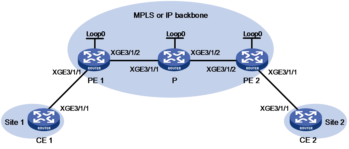
|
Device |
Interface |
IP address |
Device |
Interface |
IP address |
|
CE 1 |
XGE3/1/1 |
10.1.1.10/24 |
P |
Loop0 |
3.3.3.3/32 |
|
PE 1 |
Loop0 |
1.1.1.1/32 |
|
XGE3/1/1 |
11.1.1.2/24 |
|
|
XGE3/1/1 |
N/A |
|
XGE3/1/2 |
11.1.2.2/24 |
|
|
XGE3/1/2 |
11.1.1.1/24 |
PE 2 |
Loop0 |
2.2.2.2/32 |
|
CE 2 |
XGE3/1/1 |
10.1.1.20/24 |
|
XGE3/1/1 |
N/A |
|
|
|
|
|
XGE3/1/2 |
11.1.2.1/24 |
Procedure
1. Configure CE 1.
<CE1> system-view
[CE1] interface ten-gigabitethernet 3/1/1
[CE1-Ten-GigabitEthernet3/1/1] ip address 10.1.1.10 24
[CE1-Ten-GigabitEthernet3/1/1] quit
2. Configure PE 1:
# Configure the LSR ID.
<PE1> system-view
[PE1] interface loopback 0
[PE1-LoopBack0] ip address 1.1.1.1 32
[PE1-LoopBack0] quit
[PE1] mpls lsr-id 1.1.1.1
# Enable L2VPN.
[PE1] l2vpn enable
# Enable global LDP.
[PE1] mpls ldp
[PE1-ldp] quit
# Configure Ten-GigabitEthernet 3/1/2 (the interface connected to the P device), and enable LDP on the interface.
[PE1] interface ten-gigabitethernet 3/1/2
[PE1-Ten-GigabitEthernet3/1/2] ip address 11.1.1.1 24
[PE1-Ten-GigabitEthernet3/1/2] mpls enable
[PE1-Ten-GigabitEthernet3/1/2] mpls ldp enable
[PE1-Ten-GigabitEthernet3/1/2] quit
# Configure OSPF for LDP to create LSPs.
[PE1] ospf
[PE1-ospf-1] area 0
[PE1-ospf-1-area-0.0.0.0] network 11.1.1.0 0.0.0.255
[PE1-ospf-1-area-0.0.0.0] network 1.1.1.1 0.0.0.0
[PE1-ospf-1-area-0.0.0.0] quit
[PE1-ospf-1] quit
# Create an IBGP connection to PE 2, and enable BGP to advertise L2VPN information to PE 2.
[PE1] bgp 100
[PE1-bgp-default] peer 2.2.2.2 as-number 100
[PE1-bgp-default] peer 2.2.2.2 connect-interface loopback 0
[PE1-bgp-default] address-family l2vpn evpn
[PE1-bgp-default-evpn] peer 2.2.2.2 enable
[PE1-bgp-default-evpn] peer 2.2.2.2 advertise encap-type mpls
[PE1-bgp-default-evpn] quit
[PE1-bgp-default] quit
# Create VSI vpna, create an EVPN instance on the VSI, enable MPLS encapsulation, and configure an RD and route targets for the EVPN instance.
[PE1] vsi vpna
[PE1-vsi-vpna] evpn encapsulation mpls
[PE1-vsi-vpna-evpn-mpls] route-distinguisher 1:1
[PE1-vsi-vpna-evpn-mpls] vpn-target 1:1 export-extcommunity
[PE1-vsi-vpna-evpn-mpls] vpn-target 1:1 import-extcommunity
[PE1-vsi-vpna-evpn-mpls] quit
[PE1-vsi-vpna] quit
# Map Ten-GigabitEthernet 3/1/1 (the interface connected to CE 1) to VSI vpna.
[PE1] interface ten-gigabitethernet 3/1/1
[PE1-Ten-GigabitEthernet3/1/1] xconnect vsi vpna
[PE1-Ten-GigabitEthernet3/1/1] quit
3. Configure the P device:
# Configure the LSR ID.
<P> system-view
[P] interface loopback 0
[P-LoopBack0] ip address 3.3.3.3 32
[P-LoopBack0] quit
[P] mpls lsr-id 3.3.3.3
# Enable global LDP.
[P] mpls ldp
[P-ldp] quit
# Configure Ten-GigabitEthernet 3/1/1 (the interface connected to PE 1), and enable LDP on the interface.
[P] interface ten-gigabitethernet 3/1/1
[P-Ten-GigabitEthernet3/1/1] ip address 11.1.1.2 24
[P-Ten-GigabitEthernet3/1/1] mpls enable
[P-Ten-GigabitEthernet3/1/1] mpls ldp enable
[P-Ten-GigabitEthernet3/1/1] quit
# Configure Ten-GigabitEthernet 3/1/2 (the interface connected to PE 2), and enable LDP on the interface.
[P] interface ten-gigabitethernet 3/1/2
[P-Ten-GigabitEthernet3/1/2] ip address 11.1.2.2 24
[P-Ten-GigabitEthernet3/1/2] mpls enable
[P-Ten-GigabitEthernet3/1/2] mpls ldp enable
[P-Ten-GigabitEthernet3/1/2] quit
# Configure OSPF for LDP to create LSPs.
[P] ospf
[P-ospf-1] area 0
[P-ospf-1-area-0.0.0.0] network 11.1.1.0 0.0.0.255
[P-ospf-1-area-0.0.0.0] network 11.1.2.0 0.0.0.255
[P-ospf-1-area-0.0.0.0] network 3.3.3.3 0.0.0.0
[P-ospf-1-area-0.0.0.0] quit
[P-ospf-1] quit
4. Configure PE 2:
# Configure the LSR ID.
<PE2> system-view
[PE2] interface loopback 0
[PE2-LoopBack0] ip address 2.2.2.2 32
[PE2-LoopBack0] quit
[PE2] mpls lsr-id 2.2.2.2
# Enable L2VPN.
[PE2] l2vpn enable
# Enable global LDP.
[PE2] mpls ldp
[PE2-ldp] quit
# Configure Ten-GigabitEthernet 3/1/2 (the interface connected to the P device), and enable LDP on the interface.
[PE2] interface ten-gigabitethernet 3/1/2
[PE2-Ten-GigabitEthernet3/1/2] ip address 11.1.2.1 24
[PE2-Ten-GigabitEthernet3/1/2] mpls enable
[PE2-Ten-GigabitEthernet3/1/2] mpls ldp enable
[PE2-Ten-GigabitEthernet3/1/2] quit
# Configure OSPF for LDP to create LSPs.
[PE2] ospf
[PE2-ospf-1] area 0
[PE2-ospf-1-area-0.0.0.0] network 2.2.2.2 0.0.0.0
[PE2-ospf-1-area-0.0.0.0] network 11.1.2.0 0.0.0.255
[PE2-ospf-1-area-0.0.0.0] quit
[PE2-ospf-1] quit
# Create an IBGP connection to PE 1, and enable BGP to advertise L2VPN information to PE 1.
[PE2] bgp 100
[PE2-bgp-default] peer 1.1.1.1 as-number 100
[PE2-bgp-default] peer 1.1.1.1 connect-interface loopback 0
[PE2-bgp-default] address-family l2vpn evpn
[PE2-bgp-default-evpn] peer 1.1.1.1 enable
[PE2-bgp-default-evpn] peer 1.1.1.1 advertise encap-type mpls
[PE2-bgp-default-evpn] quit
[PE2-bgp-default] quit
# Create VSI vpna, create an EVPN instance on the VSI, enable MPLS encapsulation, and configure an RD and route targets for the EVPN instance.
[PE2] vsi vpna
[PE2-vsi-vpna] evpn encapsulation mpls
[PE2-vsi-vpna-evpn-mpls] route-distinguisher 1:1
[PE2-vsi-vpna-evpn-mpls] vpn-target 1:1 export-extcommunity
[PE2-vsi-vpna-evpn-mpls] vpn-target 1:1 import-extcommunity
[PE2-vsi-vpna-evpn-mpls] quit
[PE2-vsi-vpna] quit
# Map Ten-GigabitEthernet 3/1/1 (the interface connected to CE 2) to VSI vpna.
[PE2] interface ten-gigabitethernet 3/1/1
[PE2-Ten-GigabitEthernet3/1/1] xconnect vsi vpna
[PE2-Ten-GigabitEthernet3/1/1] quit
5. Configure CE 2.
<CE2> system-view
[CE2] interface ten-gigabitethernet 3/1/1
[CE2-Ten-GigabitEthernet3/1/1] ip address 10.1.1.20 24
[CE2-Ten-GigabitEthernet3/1/1] quit
Verifying the configuration
# Verify that an EVPN PW has been established between PE 1 and PE 2.
[PE1] display l2vpn pw
Flags: M - main, B - backup, E - ecmp, BY - bypass, H - hub link, S - spoke link
N - no split horizon, A - administration, ABY - ac-bypass
PBY - pw-bypass
Total number of PWs: 1
1 up, 0 blocked, 0 down, 0 defect, 0 idle, 0 duplicate
VSI Name: vpna
Peer PWID/RmtSite/SrvID In/Out Label Proto Flag Link ID State
2.2.2.2 - 775127/775127 EVPN M 8 Up
# Display PW information on PE 2.
[PE2] display l2vpn pw
Flags: M - main, B - backup, E - ecmp, BY - bypass, H - hub link, S - spoke link
N - no split horizon, A - administration, ABY - ac-bypass
PBY - pw-bypass
Total number of PWs: 1
1 up, 0 blocked, 0 down, 0 defect, 0 idle, 0 duplicate
VSI Name: vpna
Peer PWID/RmtSite/SrvID In/Out Label Proto Flag Link ID State
1.1.1.1 - 775127/775127 EVPN M 8 Up
# Verify that CE 1 and CE 2 can ping each other. (Details not shown.)
Example: Configuring EVPN VPLS multihoming (access through aggregate links)
Network configuration
As shown in Figure 13, configure EVPN VPLS for dualhomed site 1 and singlehomed site 2 to communicate over the MPLS or IP backbone network.

|
Device |
Interface |
IP address |
Device |
Interface |
IP address |
|
PE 1 |
Loop0 |
192.1.1.1/32 |
CE 1 |
RAGG1 |
100.1.1.1/24 |
|
|
XGE3/1/1 |
N/A |
CE 2 |
XGE3/1/1 |
100.1.1.2/24 |
|
|
XGE3/1/2 |
10.1.1.1/24 |
PE 3 |
Loop0 |
192.3.3.3/32 |
|
|
XGE3/1/3 |
10.1.3.1/24 |
|
XGE3/1/1 |
N/A |
|
PE 2 |
Loop0 |
192.2.2.2/32 |
|
XGE3/1/2 |
10.1.1.2/24 |
|
|
XGE3/1/1 |
N/A |
|
XGE3/1/3 |
10.1.2.2/24 |
|
|
XGE3/1/2 |
10.1.2.1/24 |
|
|
|
|
|
XGE3/1/3 |
10.1.3.2/24 |
|
|
|
Procedure
1. Configure CE 1:
# Create static Layer 3 aggregate interface 1 and assign it an IP address.
<CE1> system-view
[CE1] interface route-aggregation 1
[CE1-Route-Aggregation1] ip address 100.1.1.1 24
[CE1-Route-Aggregation1] quit
# Assign Ten-GigabitEthernet 3/1/1 and Ten-GigabitEthernet 3/1/2 to aggregation group 1.
[CE1] interface ten-gigabitethernet 3/1/1
[CE1-Ten-GigabitEthernet3/1/1] port link-aggregation group 1
[CE1-Ten-GigabitEthernet3/1/1] quit
[CE1] interface ten-gigabitethernet 3/1/2
[CE1-Ten-GigabitEthernet3/1/2] port link-aggregation group 1
[CE1-Ten-GigabitEthernet3/1/2] quit
2. Configure PE 1:
# Configure the LSR ID.
<PE1> system-view
[PE1] interface loopback 0
[PE1-LoopBack0] ip address 192.1.1.1 32
[PE1-LoopBack0] quit
[PE1] mpls lsr-id 192.1.1.1
# Enable L2VPN.
[PE1] l2vpn enable
# Enable global LDP.
[PE1] mpls ldp
[PE1-ldp] quit
# Configure Ten-GigabitEthernet 3/1/2 (the interface connected to PE 3), and enable LDP on the interface.
[PE1] interface ten-gigabitethernet 3/1/2
[PE1-Ten-GigabitEthernet3/1/2] ip address 10.1.1.1 24
[PE1-Ten-GigabitEthernet3/1/2] mpls enable
[PE1-Ten-GigabitEthernet3/1/2] mpls ldp enable
[PE1-Ten-GigabitEthernet3/1/2] quit
# Configure Ten-GigabitEthernet 3/1/3 (the interface connected to PE 2), and enable LDP on the interface.
[PE1] interface ten-gigabitethernet 3/1/3
[PE1-Ten-GigabitEthernet3/1/3] ip address 10.1.3.1 24
[PE1-Ten-GigabitEthernet3/1/3] mpls enable
[PE1-Ten-GigabitEthernet3/1/3] mpls ldp enable
[PE1-Ten-GigabitEthernet3/1/3] quit
# Configure OSPF for LDP to create LSPs.
[PE1] ospf
[PE1-ospf-1] area 0
[PE1-ospf-1-area-0.0.0.0] network 10.1.1.0 0.0.0.255
[PE1-ospf-1-area-0.0.0.0] network 10.1.3.0 0.0.0.255
[PE1-ospf-1-area-0.0.0.0] network 192.1.1.1 0.0.0.0
[PE1-ospf-1-area-0.0.0.0] quit
[PE1-ospf-1] quit
# Create IBGP connections to PE 2 and PE 3, and enable BGP to advertise routes to PE 2 and PE 3.
[PE1] bgp 100
[PE1-bgp-default] peer 192.2.2.2 as-number 100
[PE1-bgp-default] peer 192.2.2.2 connect-interface loopback 0
[PE1-bgp-default] peer 192.3.3.3 as-number 100
[PE1-bgp-default] peer 192.3.3.3 connect-interface loopback 0
[PE1-bgp-default] address-family l2vpn evpn
[PE1-bgp-default-evpn] peer 192.2.2.2 enable
[PE1-bgp-default-evpn] peer 192.3.3.3 enable
[PE1-bgp-default-evpn] peer 192.2.2.2 advertise encap-type mpls
[PE1-bgp-default-evpn] peer 192.3.3.3 advertise encap-type mpls
[PE1-bgp-default-evpn] quit
[PE1-bgp-default] quit
# Assign an ESI to Ten-GigabitEthernet 3/1/1.
[PE1] interface ten-gigabitethernet 3/1/1
[PE1-Ten-GigabitEthernet3/1/1] esi 1.1.1.1.1
[PE1-Ten-GigabitEthernet3/1/1] quit
# Create VSI vpna, create an EVPN instance on the VSI, enable MPLS encapsulation, and configure an RD and route targets for the EVPN instance.
[PE1] vsi vpna
[PE1-vsi-vpna] evpn encapsulation mpls
[PE1-vsi-vpna-evpn-mpls] route-distinguisher 1:1
[PE1-vsi-vpna-evpn-mpls] vpn-target 1:1 export-extcommunity
[PE1-vsi-vpna-evpn-mpls] vpn-target 1:1 import-extcommunity
[PE1-vsi-vpna-evpn-mpls] quit
[PE1-vsi-vpna] quit
# Map Ten-GigabitEthernet 3/1/1 (the interface connected to CE 1) to VSI vpna.
[PE1] interface ten-gigabitethernet 3/1/1
[PE1-Ten-GigabitEthernet3/1/1] xconnect vsi vpna
[PE1-Ten-GigabitEthernet3/1/1] quit
3. Configure PE 2:
# Configure the LSR ID.
<PE2> system-view
[PE2] interface loopback 0
[PE2-LoopBack0] ip address 192.2.2.2 32
[PE2-LoopBack0] quit
[PE2] mpls lsr-id 192.2.2.2
# Enable L2VPN.
[PE2] l2vpn enable
# Enable global LDP.
[PE2] mpls ldp
[PE2-ldp] quit
# Configure Ten-GigabitEthernet 3/1/2 (the interface connected to PE 3), and enable LDP on the interface.
[PE2] interface ten-gigabitethernet 3/1/2
[PE2-Ten-GigabitEthernet3/1/2] ip address 10.1.2.1 24
[PE2-Ten-GigabitEthernet3/1/2] mpls enable
[PE2-Ten-GigabitEthernet3/1/2] mpls ldp enable
[PE2-Ten-GigabitEthernet3/1/2] quit
# Configure Ten-GigabitEthernet 3/1/3 (the interface connected to PE 1), and enable LDP on the interface.
[PE2] interface ten-gigabitethernet 3/1/3
[PE2-Ten-GigabitEthernet3/1/3] ip address 10.1.3.2 24
[PE2-Ten-GigabitEthernet3/1/3] mpls enable
[PE2-Ten-GigabitEthernet3/1/3] mpls ldp enable
[PE2-Ten-GigabitEthernet3/1/3] quit
# Configure OSPF for LDP to create LSPs.
[PE2] ospf
[PE2-ospf-1] area 0
[PE2-ospf-1-area-0.0.0.0] network 10.1.2.0 0.0.0.255
[PE2-ospf-1-area-0.0.0.0] network 10.1.3.0 0.0.0.255
[PE2-ospf-1-area-0.0.0.0] network 192.2.2.2 0.0.0.0
[PE2-ospf-1-area-0.0.0.0] quit
[PE2-ospf-1] quit
# Create IBGP connections to PE 1 and PE 3, and enable BGP to advertise routes to PE 1 and PE 3.
[PE2] bgp 100
[PE2-bgp-default] peer 192.1.1.1 as-number 100
[PE2-bgp-default] peer 192.1.1.1 connect-interface loopback 0
[PE2-bgp-default] peer 192.3.3.3 as-number 100
[PE2-bgp-default] peer 192.3.3.3 connect-interface loopback 0
[PE2-bgp-default] address-family l2vpn evpn
[PE2-bgp-default-evpn] peer 192.1.1.1 enable
[PE2-bgp-default-evpn] peer 192.3.3.3 enable
[PE2-bgp-default-evpn] peer 192.1.1.1 advertise encap-type mpls
[PE2-bgp-default-evpn] peer 192.3.3.3 advertise encap-type mpls
[PE2-bgp-default-evpn] quit
[PE2-bgp-default] quit
# Assign an ESI to Ten-GigabitEthernet 3/1/1.
[PE2] interface ten-gigabitethernet 3/1/1
[PE2-Ten-GigabitEthernet3/1/1] esi 1.1.1.1.1
[PE2-Ten-GigabitEthernet3/1/1] quit
# Create VSI vpna, create an EVPN instance on the VSI, enable MPLS encapsulation, and configure an RD and route targets for the EVPN instance.
[PE2] vsi vpna
[PE2-vsi-vpna] evpn encapsulation mpls
[PE2-vsi-vpna-evpn-mpls] route-distinguisher 1:1
[PE2-vsi-vpna-evpn-mpls] vpn-target 1:1 export-extcommunity
[PE2-vsi-vpna-evpn-mpls] vpn-target 1:1 import-extcommunity
[PE2-vsi-vpna-evpn-mpls] quit
[PE2-vsi-vpna] quit
# Map Ten-GigabitEthernet 3/1/1 (the interface connected to CE 1) to VSI vpna.
[PE2] interface ten-gigabitethernet 3/1/1
[PE2-Ten-GigabitEthernet3/1/1] xconnect vsi vpna
[PE2-Ten-GigabitEthernet3/1/1] quit
4. Configure PE 3:
# Configure the LSR ID.
<PE3> system-view
[PE3] interface loopback 0
[PE3-LoopBack0] ip address 192.3.3.3 32
[PE3-LoopBack0] quit
[PE3] mpls lsr-id 192.3.3.3
# Enable L2VPN.
[PE3] l2vpn enable
# Enable global LDP.
[PE3] mpls ldp
[PE3-ldp] quit
# Configure Ten-GigabitEthernet 3/1/2 (the interface connected to PE 1) and Ten-GigabitEthernet 3/1/3 (the interface connected to PE 2), and enable LDP on the interfaces.
[PE3] interface ten-gigabitethernet 3/1/2
[PE3-Ten-GigabitEthernet3/1/2] ip address 10.1.1.2 24
[PE3-Ten-GigabitEthernet3/1/2] mpls enable
[PE3-Ten-GigabitEthernet3/1/2] mpls ldp enable
[PE3-Ten-GigabitEthernet3/1/2] quit
[PE3] interface ten-gigabitethernet 3/1/3
[PE3-Ten-GigabitEthernet3/1/3] ip address 10.1.2.2 24
[PE3-Ten-GigabitEthernet3/1/3] mpls enable
[PE3-Ten-GigabitEthernet3/1/3] mpls ldp enable
[PE3-Ten-GigabitEthernet3/1/3] quit
# Configure OSPF for LDP to create LSPs.
[PE3] ospf
[PE3-ospf-1] area 0
[PE3-ospf-1-area-0.0.0.0] network 192.3.3.3 0.0.0.0
[PE3-ospf-1-area-0.0.0.0] network 10.1.1.0 0.0.0.255
[PE3-ospf-1-area-0.0.0.0] network 10.1.2.0 0.0.0.255
[PE3-ospf-1-area-0.0.0.0] quit
[PE3-ospf-1] quit
# Create IBGP connections to PE 1 and PE 2, and enable BGP to advertise routes to PE 1 and PE 2.
[PE3] bgp 100
[PE3-bgp-default] peer 192.1.1.1 as-number 100
[PE3-bgp-default] peer 192.1.1.1 connect-interface loopback 0
[PE3-bgp-default] peer 192.2.2.2 as-number 100
[PE3-bgp-default] peer 192.2.2.2 connect-interface loopback 0
[PE3-bgp-default] address-family l2vpn evpn
[PE3-bgp-default-evpn] peer 192.1.1.1 enable
[PE3-bgp-default-evpn] peer 192.2.2.2 enable
[PE3-bgp-default-evpn] peer 192.1.1.1 advertise encap-type mpls
[PE3-bgp-default-evpn] peer 192.2.2.2 advertise encap-type mpls
[PE3-bgp-default-evpn] quit
[PE3-bgp-default] quit
# Create VSI vpna, create an EVPN instance on the VSI, enable MPLS encapsulation, and configure an RD and route targets for the EVPN instance.
[PE3] vsi vpna
[PE3-vsi-vpna] evpn encapsulation mpls
[PE3-vsi-vpna-evpn-mpls] route-distinguisher 1:1
[PE3-vsi-vpna-evpn-mpls] vpn-target 1:1 export-extcommunity
[PE3-vsi-vpna-evpn-mpls] vpn-target 1:1 import-extcommunity
[PE3-vsi-vpna-evpn-mpls] quit
[PE3-vsi-vpna] quit
# Map Ten-GigabitEthernet 3/1/1 (the interface connected to CE 2) to VSI vpna.
[PE3] interface ten-gigabitethernet 3/1/1
[PE3-Ten-GigabitEthernet3/1/1] xconnect vsi vpna
[PE3-Ten-GigabitEthernet3/1/1] quit
5. Configure CE 2.
<CE2> system-view
[CE2] interface ten-gigabitethernet 3/1/1
[CE2-Ten-GigabitEthernet3/1/1] ip address 100.1.1.2 24
[CE2-Ten-GigabitEthernet3/1/1] quit
Verifying the configuration
# Verify that PE 1 has established EVPN PWs to PE 2 and PE 3.
<PE1> display l2vpn pw
Flags: M - main, B - backup, E - ecmp, BY - bypass, H - hub link, S - spoke link
N - no split horizon, A - administration, ABY - ac-bypass
PBY - pw-bypass
Total number of PWs: 2
2 up, 0 blocked, 0 down, 0 defect, 0 idle, 0 duplicate
VSI name: vpna
Peer PWID/RmtSite/SrvID In/Out Label Proto Flag Link ID State
192.3.3.3 - 710263/710265 EVPN M 8 Up
192.2.2.2 - 710263/710124 EVPN M 9 Up
# Verify that PE 1 has local ES information.
<PE1> display evpn es local
Redundancy mode: A - All-active, S - Single-active
VSI name : vpna
ESI Tag ID DF address Mode State ESI label
0001.0001.0001.0001.0001 0 192.1.1.1 A Up 775128
# Verify that PE 1 has remote ES information.
<PE1> display evpn es remote
Control Flags: P - Primary, B - Backup, C - Control word
VSI name : vpna
ESI : 0001.0001.0001.0001.0001
Ethernet segment routes :
192.2.2.2
A-D per ES routes :
Peer IP Remote Redundancy mode
192.2.2.2 All-active
A-D per EVI routes :
Tag ID Peer IP Control Flags
0 192.2.2.2 B
# Verify that PE 2 has established EVPN PWs to PE 1 and PE 3.
<PE2> display l2vpn pw
Flags: M - main, B - backup, E - ecmp, BY - bypass, H - hub link, S - spoke link
N - no split horizon, A - administration, ABY - ac-bypass
PBY - pw-bypass
Total number of PWs: 2
2 up, 0 blocked, 0 down, 0 defect, 0 idle, 0 duplicate
VSI name: vpna
Peer PWID/RmtSite/SrvID In/Out Label Proto Flag Link ID State
192.1.1.1 - 710124/710263 EVPN M 8 Up
192.3.3.3 - 710124/710265 EVPN M 9 Up
# Verify that PE 3 has established EVPN PWs to PE 1 and PE 2.
<PE3> display l2vpn pw
Flags: M - main, B - backup, E - ecmp, BY - bypass, H - hub link, S - spoke link
N - no split horizon, A - administration, ABY - ac-bypass
PBY - pw-bypass
Total number of PWs: 2
2 up, 0 blocked, 0 down, 0 defect, 0 idle, 0 duplicate
VSI name: vpna
Peer PWID/RmtSite/SrvID In/Out Label Proto Flag Link ID State
192.1.1.1 - 710265/710263 EVPN M 8 Up
192.2.2.2 - 710265/710124 EVPN M 9 Up
# Verify that CE 1 and CE 2 can ping each other when the PW on PE 1 or PE 2 fails. (Details not shown.)
Example: Configuring EVPN VPLS multihoming (access through an S-Trunk system)
Network configuration
As shown in Figure 14, configure EVPN VPLS for dualhomed site 1 and singlehomed site 2 to communicate over the MPLS or IP backbone network. Configure PE 1 and PE 2 to form an S-Trunk system.

|
Device |
Interface |
IP address |
Device |
Interface |
IP address |
|
PE 1 |
Loop0 |
192.1.1.1/32 |
CE 1 |
RAGG1 |
100.1.1.1/24 |
|
|
XGE3/1/1 |
- |
CE 2 |
XGE3/1/1 |
100.1.1.2/24 |
|
|
XGE3/1/2 |
10.1.1.1/24 |
PE 3 |
Loop0 |
192.3.3.3/32 |
|
|
XGE3/1/3 |
10.1.3.1/24 |
|
XGE3/1/1 |
- |
|
PE 2 |
Loop0 |
192.2.2.2/32 |
|
XGE3/1/2 |
10.1.1.2/24 |
|
|
XGE3/1/1 |
- |
|
XGE3/1/3 |
10.1.2.2/24 |
|
|
XGE3/1/2 |
10.1.2.1/24 |
|
|
|
|
|
XGE3/1/3 |
10.1.3.2/24 |
|
|
|
Procedure
1. Configure CE 1:
# Create dynamic Layer 3 aggregate interface 1 and assign it an IP address.
<CE1> system-view
[CE1] interface route-aggregation 1
[CE1-Route-Aggregation1] link-aggregation mode dynamic
[CE1-Route-Aggregation1] ip address 100.1.1.1 24
[CE1-Route-Aggregation1] quit
# Assign Ten-GigabitEthernet 3/1/1 and Ten-GigabitEthernet 3/1/2 to aggregation group 1.
[CE1] interface ten-gigabitethernet 3/1/1
[CE1-Ten-GigabitEthernet3/1/1] port link-aggregation group 1
[CE1-Ten-GigabitEthernet3/1/1] quit
[CE1] interface ten-gigabitethernet 3/1/2
[CE1-Ten-GigabitEthernet3/1/2] port link-aggregation group 1
[CE1-Ten-GigabitEthernet3/1/2] quit
2. Configure PE 1:
# Configure the LSR ID.
<PE1> system-view
[PE1] interface loopback 0
[PE1-LoopBack0] ip address 192.1.1.1 32
[PE1-LoopBack0] quit
[PE1] mpls lsr-id 192.1.1.1
# Enable L2VPN.
[PE1] l2vpn enable
# Enable global LDP.
[PE1] mpls ldp
[PE1-ldp] quit
# Configure Ten-GigabitEthernet 3/1/2 (the interface connected to PE 3), and enable LDP on the interface.
[PE1] interface ten-gigabitethernet 3/1/2
[PE1-Ten-GigabitEthernet3/1/2] ip address 10.1.1.1 24
[PE1-Ten-GigabitEthernet3/1/2] mpls enable
[PE1-Ten-GigabitEthernet3/1/2] mpls ldp enable
[PE1-Ten-GigabitEthernet3/1/2] quit
# Configure Ten-GigabitEthernet 3/1/3 (the interface connected to PE 2), and enable LDP on the interface.
[PE1] interface ten-gigabitethernet 3/1/3
[PE1-Ten-GigabitEthernet3/1/3] ip address 10.1.3.1 24
[PE1-Ten-GigabitEthernet3/1/3] mpls enable
[PE1-Ten-GigabitEthernet3/1/3] mpls ldp enable
[PE1-Ten-GigabitEthernet3/1/3] quit
# Configure OSPF for LDP to create LSPs.
[PE1] ospf
[PE1-ospf-1] area 0
[PE1-ospf-1-area-0.0.0.0] network 10.1.1.0 0.0.0.255
[PE1-ospf-1-area-0.0.0.0] network 10.1.3.0 0.0.0.255
[PE1-ospf-1-area-0.0.0.0] network 192.1.1.1 0.0.0.0
[PE1-ospf-1-area-0.0.0.0] quit
[PE1-ospf-1] quit
# Create IBGP connections to PE 2 and PE 3, and enable BGP to advertise routes to PE 2 and PE 3.
[PE1] bgp 100
[PE1-bgp-default] peer 192.2.2.2 as-number 100
[PE1-bgp-default] peer 192.2.2.2 connect-interface loopback 0
[PE1-bgp-default] peer 192.3.3.3 as-number 100
[PE1-bgp-default] peer 192.3.3.3 connect-interface loopback 0
[PE1-bgp-default] address-family l2vpn evpn
[PE1-bgp-default-evpn] peer 192.2.2.2 enable
[PE1-bgp-default-evpn] peer 192.3.3.3 enable
[PE1-bgp-default-evpn] peer 192.2.2.2 advertise encap-type mpls
[PE1-bgp-default-evpn] peer 192.3.3.3 advertise encap-type mpls
[PE1-bgp-default-evpn] quit
[PE1-bgp-default] quit
# Configure S-Trunk to set up a multichassis aggregate link to CE 1.
[PE1] lacp system-priority 10
[PE1] lacp system-mac 1-1-1
[PE1] lacp system-number 1
[PE1] s-trunk id 1
[PE1-s-trunk1] s-trunk ip destination 10.1.3.2 source 10.1.3.1
[PE1-s-trunk1] quit
[PE1] interface route-aggregation 1
[PE1-Route-Aggregation1] link-aggregation mode dynamic
[PE1-Route-Aggregation1] s-trunk 1
[PE1-Route-Aggregation1] s-trunk port-role primary
[PE1-Route-Aggregation1] quit
[PE1] interface ten-gigabitethernet 3/1/1
[PE1-Ten-GigabitEthernet3/1/1] port link-aggregation group 1
[PE1-Ten-GigabitEthernet3/1/1] quit
# On Route-Aggregation 1, configure an ESI and enable all-active redundancy mode.
[PE1] interface route-aggregation 1
[PE1-Route-Aggregation1] esi 1.1.1.1.1
[PE1-Route-Aggregation1] evpn redundancy-mode all-active
[PE1-Route-Aggregation1] quit
# Create VSI vpna, create an EVPN instance on the VSI, enable MPLS encapsulation, and configure an RD and route targets for the EVPN instance.
[PE1] vsi vpna
[PE1-vsi-vpna] evpn encapsulation mpls
[PE1-vsi-vpna-evpn-mpls] route-distinguisher 1:1
[PE1-vsi-vpna-evpn-mpls] vpn-target 1:1 export-extcommunity
[PE1-vsi-vpna-evpn-mpls] vpn-target 1:1 import-extcommunity
[PE1-vsi-vpna-evpn-mpls] quit
[PE1-vsi-vpna] quit
# Map Route-Aggregation 1 (the interface connected to CE 1) to VSI vpna.
[PE1] interface route-aggregation 1
[PE1-Route-Aggregation1] xconnect vsi vpna
[PE1-Route-Aggregation1] quit
3. Configure PE 2:
# Configure the LSR ID.
<PE2> system-view
[PE2] interface loopback 0
[PE2-LoopBack0] ip address 192.2.2.2 32
[PE2-LoopBack0] quit
[PE2] mpls lsr-id 192.2.2.2
# Enable L2VPN.
[PE2] l2vpn enable
# Enable global LDP.
[PE2] mpls ldp
[PE2-ldp] quit
# Configure Ten-GigabitEthernet 3/1/2 (the interface connected to PE 3), and enable LDP on the interface.
[PE2] interface ten-gigabitethernet 3/1/2
[PE2-Ten-GigabitEthernet3/1/2] ip address 10.1.2.1 24
[PE2-Ten-GigabitEthernet3/1/2] mpls enable
[PE2-Ten-GigabitEthernet3/1/2] mpls ldp enable
[PE2-Ten-GigabitEthernet3/1/2] quit
# Configure Ten-GigabitEthernet 3/1/3 (the interface connected to PE 1), and enable LDP on the interface.
[PE2] interface ten-gigabitethernet 3/1/3
[PE2-Ten-GigabitEthernet3/1/3] ip address 10.1.3.2 24
[PE2-Ten-GigabitEthernet3/1/3] mpls enable
[PE2-Ten-GigabitEthernet3/1/3] mpls ldp enable
[PE2-Ten-GigabitEthernet3/1/3] quit
# Configure OSPF for LDP to create LSPs.
[PE2] ospf
[PE2-ospf-1] area 0
[PE2-ospf-1-area-0.0.0.0] network 10.1.2.0 0.0.0.255
[PE2-ospf-1-area-0.0.0.0] network 10.1.3.0 0.0.0.255
[PE2-ospf-1-area-0.0.0.0] network 192.2.2.2 0.0.0.0
[PE2-ospf-1-area-0.0.0.0] quit
[PE2-ospf-1] quit
# Create IBGP connections to PE 1 and PE 3, and enable BGP to advertise routes to PE 1 and PE 3.
[PE2] bgp 100
[PE2-bgp-default] peer 192.1.1.1 as-number 100
[PE2-bgp-default] peer 192.1.1.1 connect-interface loopback 0
[PE2-bgp-default] peer 192.3.3.3 as-number 100
[PE2-bgp-default] peer 192.3.3.3 connect-interface loopback 0
[PE2-bgp-default] address-family l2vpn evpn
[PE2-bgp-default-evpn] peer 192.1.1.1 enable
[PE2-bgp-default-evpn] peer 192.3.3.3 enable
[PE2-bgp-default-evpn] peer 192.1.1.1 advertise encap-type mpls
[PE2-bgp-default-evpn] peer 192.3.3.3 advertise encap-type mpls
[PE2-bgp-default-evpn] quit
[PE2-bgp-default] quit
# Configure S-Trunk to set up a multichassis aggregate link to CE 1.
[PE2] lacp system-priority 10
[PE2] lacp system-mac 1-1-1
[PE2] lacp system-number 2
[PE2] s-trunk id 1
[PE2-s-trunk1] s-trunk ip destination 10.1.3.1 source 10.1.3.2
[PE2-s-trunk1] quit
[PE2] interface route-aggregation 1
[PE2-Route-Aggregation1] link-aggregation mode dynamic
[PE2-Route-Aggregation1] s-trunk 1
[PE2-Route-Aggregation1] s-trunk port-role primary
[PE2-Route-Aggregation1] quit
[PE2] interface ten-gigabitethernet 3/1/1
[PE2-Ten-GigabitEthernet3/1/1] port link-aggregation group 1
[PE2-Ten-GigabitEthernet3/1/1] quit
# On Route-Aggregation 1, configure an ESI and enable all-active redundancy mode.
[PE2] interface route-aggregation 1
[PE2-Route-Aggregation1] esi 1.1.1.1.1
[PE2-Route-Aggregation1] evpn redundancy-mode all-active
[PE2-Route-Aggregation1] quit
# Create VSI vpna, create an EVPN instance on the VSI, enable MPLS encapsulation, and configure an RD and route targets for the EVPN instance.
[PE2] vsi vpna
[PE2-vsi-vpna] evpn encapsulation mpls
[PE2-vsi-vpna-evpn-mpls] route-distinguisher 1:1
[PE2-vsi-vpna-evpn-mpls] vpn-target 1:1 export-extcommunity
[PE2-vsi-vpna-evpn-mpls] vpn-target 1:1 import-extcommunity
[PE2-vsi-vpna-evpn-mpls] quit
[PE2-vsi-vpna] quit
# Map Route-Aggregation 1 (the interface connected to CE 1) to VSI vpna.
[PE2] interface route-aggregation 1
[PE2-Route-Aggregation1] xconnect vsi vpna
[PE2-Route-Aggregation1] quit
4. Configure PE 3:
# Configure the LSR ID.
<PE3> system-view
[PE3] interface loopback 0
[PE3-LoopBack0] ip address 192.3.3.3 32
[PE3-LoopBack0] quit
[PE3] mpls lsr-id 192.3.3.3
# Enable L2VPN.
[PE3] l2vpn enable
# Enable global LDP.
[PE3] mpls ldp
[PE3-ldp] quit
# Configure Ten-GigabitEthernet 3/1/2 (the interface connected to PE 1) and Ten-GigabitEthernet 3/1/3 (the interface connected to PE 2), and enable LDP on the interfaces.
[PE3] interface ten-gigabitethernet 3/1/2
[PE3-Ten-GigabitEthernet3/1/2] ip address 10.1.1.2 24
[PE3-Ten-GigabitEthernet3/1/2] mpls enable
[PE3-Ten-GigabitEthernet3/1/2] mpls ldp enable
[PE3-Ten-GigabitEthernet3/1/2] quit
[PE3] interface ten-gigabitethernet 3/1/3
[PE3-Ten-GigabitEthernet3/1/3] ip address 10.1.2.2 24
[PE3-Ten-GigabitEthernet3/1/3] mpls enable
[PE3-Ten-GigabitEthernet3/1/3] mpls ldp enable
[PE3-Ten-GigabitEthernet3/1/3] quit
# Configure OSPF for LDP to create LSPs.
[PE3] ospf
[PE3-ospf-1] area 0
[PE3-ospf-1-area-0.0.0.0] network 192.3.3.3 0.0.0.0
[PE3-ospf-1-area-0.0.0.0] network 10.1.1.0 0.0.0.255
[PE3-ospf-1-area-0.0.0.0] network 10.1.2.0 0.0.0.255
[PE3-ospf-1-area-0.0.0.0] quit
[PE3-ospf-1] quit
# Create IBGP connections to PE 1 and PE 2, and enable BGP to advertise routes to PE 1 and PE 2.
[PE3] bgp 100
[PE3-bgp-default] peer 192.1.1.1 as-number 100
[PE3-bgp-default] peer 192.1.1.1 connect-interface loopback 0
[PE3-bgp-default] peer 192.2.2.2 as-number 100
[PE3-bgp-default] peer 192.2.2.2 connect-interface loopback 0
[PE3-bgp-default] address-family l2vpn evpn
[PE3-bgp-default-evpn] peer 192.1.1.1 enable
[PE3-bgp-default-evpn] peer 192.2.2.2 enable
[PE3-bgp-default-evpn] peer 192.1.1.1 advertise encap-type mpls
[PE3-bgp-default-evpn] peer 192.2.2.2 advertise encap-type mpls
[PE3-bgp-default-evpn] quit
[PE3-bgp-default] quit
# Create VSI vpna, create an EVPN instance on the VSI, enable MPLS encapsulation, and configure an RD and route targets for the EVPN instance.
[PE3] vsi vpna
[PE3-vsi-vpna] evpn encapsulation mpls
[PE3-vsi-vpna-evpn-mpls] route-distinguisher 1:1
[PE3-vsi-vpna-evpn-mpls] vpn-target 1:1 export-extcommunity
[PE3-vsi-vpna-evpn-mpls] vpn-target 1:1 import-extcommunity
[PE3-vsi-vpna-evpn-mpls] quit
[PE3-vsi-vpna] quit
# Map Ten-GigabitEthernet 3/1/1 (the interface connected to CE 2) to VSI vpna.
[PE3] interface ten-gigabitethernet 3/1/1
[PE3-Ten-GigabitEthernet3/1/1] xconnect vsi vpna
[PE3-Ten-GigabitEthernet3/1/1] quit
5. Configure CE 2.
<CE2> system-view
[CE2] interface ten-gigabitethernet 3/1/1
[CE2-Ten-GigabitEthernet3/1/1] ip address 100.1.1.2 24
[CE2-Ten-GigabitEthernet3/1/1] quit
Verifying the configuration
# Verify that PE 1 has established EVPN PWs to PE 2 and PE 3.
<PE1> display l2vpn pw
Flags: M - main, B - backup, E - ecmp, BY - bypass, H - hub link, S - spoke link
N - no split horizon, A - administration, ABY - ac-bypass
PBY - pw-bypass
Total number of PWs: 2
2 up, 0 blocked, 0 down, 0 defect, 0 idle, 0 duplicate
VSI name: vpna
Peer PWID/RmtSite/SrvID In/Out Label Proto Flag Link ID State
192.3.3.3 - 710263/710265 EVPN M 8 Up
192.2.2.2 - 710263/710124 EVPN M 9 Up
# Verify that PE 1 has local ES information.
<PE1> display evpn es local
Redundancy mode: A - All-active, S - Single-active
VSI name : vpna
ESI Tag ID DF address Mode State ESI label
0001.0001.0001.0001.0001 0 192.1.1.1 A Up 775128
# Verify that PE 1 has remote ES information.
<PE1> display evpn es remote
Control Flags: P - Primary, B - Backup, C - Control word
VSI name : vpna
ESI : 0001.0001.0001.0001.0001
Ethernet segment routes :
192.2.2.2
A-D per ES routes :
Peer IP Remote Redundancy mode
192.2.2.2 All-active
A-D per EVI routes :
Tag ID Peer IP Control Flags
0 192.2.2.2 B
# Verify that PE 2 has established EVPN PWs to PE 1 and PE 3.
<PE2> display l2vpn pw
Flags: M - main, B - backup, E - ecmp, BY - bypass, H - hub link, S - spoke link
N - no split horizon, A - administration, ABY - ac-bypass
PBY - pw-bypass
Total number of PWs: 2
2 up, 0 blocked, 0 down, 0 defect, 0 idle, 0 duplicate
VSI name: vpna
Peer PWID/RmtSite/SrvID In/Out Label Proto Flag Link ID State
192.1.1.1 - 710124/710263 EVPN M 8 Up
192.3.3.3 - 710124/710265 EVPN M 9 Up
# Verify that PE 3 has established EVPN PWs to PE 1 and PE 2.
<PE3> display l2vpn pw
Flags: M - main, B - backup, E - ecmp, BY - bypass, H - hub link, S - spoke link
N - no split horizon, A - administration, ABY - ac-bypass
PBY - pw-bypass
Total number of PWs: 2
2 up, 0 blocked, 0 down, 0 defect, 0 idle, 0 duplicate
VSI name: vpna
Peer PWID/RmtSite/SrvID In/Out Label Proto Flag Link ID State
192.1.1.1 - 710265/710263 EVPN M 8 Up
192.2.2.2 - 710265/710124 EVPN M 9 Up
# Verify that CE 1 and CE 2 can ping each other when the PW on PE 1 or PE 2 fails. (Details not shown.)
Example: Configuring local FRR for EVPN VPLS
Network configuration
As shown in Figure 15:
· CE 1 is dualhomed to PE 1 and PE 2 through an aggregate link.
· Configure EVPN VPLS on PE 1, PE 2, and PE 3 for CE 1 and CE 2 to communicate at Layer 2 over the backbone network.
· Enable local FRR on PE 1 and PE 2 to prevent traffic loss caused by AC failure.
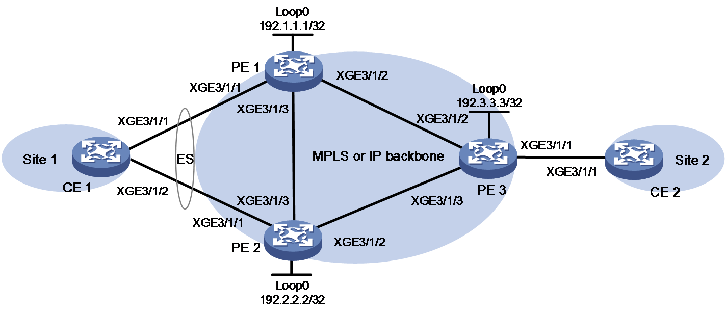
Table 1 Interface and IP address assignment
|
Device |
Interface |
IP address |
Device |
Interface |
IP address |
|
PE 1 |
Loop0 |
192.1.1.1/32 |
CE 1 |
XGE3/1/1 |
100.1.1.1/24 |
|
|
XGE3/1/1 |
- |
CE 2 |
XGE3/1/1 |
100.1.1.2/24 |
|
|
XGE3/1/2 |
10.1.1.1/24 |
PE 3 |
Loop0 |
192.3.3.3/32 |
|
|
XGE3/1/3 |
10.1.3.1/24 |
|
XGE3/1/1 |
- |
|
PE 2 |
Loop0 |
192.2.2.2/32 |
XGE3/1/2 |
10.1.1.2/24 |
|
|
XGE3/1/1 |
- |
|
XGE3/1/3 |
10.1.2.2/24 |
|
|
|
XGE3/1/2 |
10.1.2.1/24 |
|
||
|
|
XGE3/1/3 |
10.1.3.2/24 |
|
Procedure
1. Configure CE 1:
# Create dynamic Layer 3 aggregate interface Route-Aggregation 1 and assign it an IP address.
<CE1> system-view
[CE1] interface route-aggregation 1
[CE1-Route-Aggregation1] link-aggregation mode dynamic
[CE1-Route-Aggregation1] ip address 100.1.1.1 24
[CE1-Route-Aggregation1] quit
# Assign Ten-GigabitEthernet 3/1/1 and Ten-GigabitEthernet 3/1/2 to aggregation group 1.
[CE1] interface ten-gigabitethernet 3/1/1
[CE1-Ten-GigabitEthernet3/1/1] port link-aggregation group 1
[CE1-Ten-GigabitEthernet3/1/1] quit
[CE1] interface ten-gigabitethernet 3/1/2
[CE1-Ten-GigabitEthernet3/1/2] port link-aggregation group 1
[CE1-Ten-GigabitEthernet3/1/2] quit
2. Configure PE 1:
# Configure an LSR ID.
<PE1> system-view
[PE1] interface loopback 0
[PE1-LoopBack0] ip address 192.1.1.1 32
[PE1-LoopBack0] quit
[PE1] mpls lsr-id 192.1.1.1
# Enable L2VPN.
[PE1] l2vpn enable
# Enable global LDP.
[PE1] mpls ldp
[PE1-ldp] quit
# Configure Ten-GigabitEthernet 3/1/2 (the interface connected to PE3), and enable MPLS and LDP on the interface.
[PE1] interface ten-gigabitethernet 3/1/2
[PE1-Ten-GigabitEthernet3/1/2] ip address 10.1.1.1 24
[PE1-Ten-GigabitEthernet3/1/2] mpls enable
[PE1-Ten-GigabitEthernet3/1/2] mpls ldp enable
[PE1-Ten-GigabitEthernet3/1/2] quit
# Configure Ten-GigabitEthernet 3/1/3 (the interface connected to PE 2), and enable MPLS and LDP on the interface.
[PE1] interface ten-gigabitethernet 3/1/3
[PE1-Ten-GigabitEthernet3/1/3] ip address 10.1.3.1 24
[PE1-Ten-GigabitEthernet3/1/3] mpls enable
[PE1-Ten-GigabitEthernet3/1/3] mpls ldp enable
[PE1-Ten-GigabitEthernet3/1/3] quit
# Configure OSPF for LDP to create LSPs.
[PE1] ospf
[PE1-ospf-1] area 0
[PE1-ospf-1-area-0.0.0.0] network 10.1.1.0 0.0.0.255
[PE1-ospf-1-area-0.0.0.0] network 10.1.3.0 0.0.0.255
[PE1-ospf-1-area-0.0.0.0] network 192.1.1.1 0.0.0.0
[PE1-ospf-1-area-0.0.0.0] quit
[PE1-ospf-1] quit
# Configure PE 1 to establish IBGP peer relationships with PE 2 and PE 3, and configure BGP to advertise BGP EVPN routes.
[PE1] bgp 100
[PE1-bgp-default] peer 192.2.2.2 as-number 100
[PE1-bgp-default] peer 192.2.2.2 connect-interface loopback 0
[PE1-bgp-default] peer 192.3.3.3 as-number 100
[PE1-bgp-default] peer 192.3.3.3 connect-interface loopback 0
[PE1-bgp-default] address-family l2vpn evpn
[PE1-bgp-default-evpn] peer 192.2.2.2 enable
[PE1-bgp-default-evpn] peer 192.3.3.3 enable
[PE1-bgp-default-evpn] peer 192.2.2.2 advertise encap-type mpls
[PE1-bgp-default-evpn] peer 192.3.3.3 advertise encap-type mpls
[PE1-bgp-default-evpn] quit
[PE1-bgp-default] quit
# Configure a smart trunk to establish an aggregate link across PE 1 and PE 2.
[PE1] lacp system-priority 10
[PE1] lacp system-mac 1-1-1
[PE1] lacp system-number 1
[PE1] s-trunk id 1
[PE1-s-trunk1] s-trunk ip destination 10.1.3.2 source 10.1.3.1
[PE1-s-trunk1] quit
[PE1] interface route-aggregation 1
[PE1-Route-Aggregation1] link-aggregation mode dynamic
[PE1-Route-Aggregation1] s-trunk 1
[PE1-Route-Aggregation1] quit
[PE1] interface ten-gigabitethernet 3/1/1
[PE1-Ten-GigabitEthernet3/1/1] port link-aggregation group 1
[PE1-Ten-GigabitEthernet3/1/1] quit
# Create VSI vpna, create an EVPN instance on it, and enable MPLS encapsulation. Configure an RD and route targets for the EVPN instance.
[PE1] vsi vpna
[PE1-vsi-vpna] evpn encapsulation mpls
[PE1-vsi-vpna-evpn-mpls] route-distinguisher 1:1
[PE1-vsi-vpna-evpn-mpls] vpn-target 1:1 export-extcommunity
[PE1-vsi-vpna-evpn-mpls] vpn-target 1:1 import-extcommunity
[PE1-vsi-vpna-evpn-mpls] quit
[PE1-vsi-vpna] quit
# Assign an ESI to Route-Aggregation 1.
[PE1] interface route-aggregation 1
[PE1-Route-Aggregation1] esi 1.1.1.1.1
# Map Route-Aggregation 1 to VSI vpna.
[PE1-Route-Aggregation1] xconnect vsi vpna
[PE1-Route-Aggregation1] quit
# Enable local FRR for EVPN VPLS globally.
[PE1] evpn multihoming vpls-frr local
3. Configure PE 2:
# Configure an LSR ID.
<PE2> system-view
[PE2] interface loopback 0
[PE2-LoopBack0] ip address 192.2.2.2 32
[PE2-LoopBack0] quit
[PE2] mpls lsr-id 192.2.2.2
# Enable L2VPN.
[PE2] l2vpn enable
# Enable global LDP.
[PE2] mpls ldp
[PE2-ldp] quit
# Configure Ten-GigabitEthernet 3/1/2 (the interface connected to PE 3), and enable MPLS and LDP on the interface.
[PE2] interface ten-gigabitethernet 3/1/2
[PE2-Ten-GigabitEthernet3/1/2] ip address 10.1.2.1 24
[PE2-Ten-GigabitEthernet3/1/2] mpls enable
[PE2-Ten-GigabitEthernet3/1/2] mpls ldp enable
[PE2-Ten-GigabitEthernet3/1/2] quit
# Configure Ten-GigabitEthernet 3/1/3 (the interface connected to PE 1), and enable MPLS and LDP on the interface.
[PE2] interface ten-gigabitethernet 3/1/3
[PE2-Ten-GigabitEthernet3/1/3] ip address 10.1.3.2 24
[PE2-Ten-GigabitEthernet3/1/3] mpls enable
[PE2-Ten-GigabitEthernet3/1/3] mpls ldp enable
[PE2-Ten-GigabitEthernet3/1/3] quit
# Configure OSPF for LDP to create LSPs.
[PE2] ospf
[PE2-ospf-1] area 0
[PE2-ospf-1-area-0.0.0.0] network 10.1.2.0 0.0.0.255
[PE2-ospf-1-area-0.0.0.0] network 10.1.3.0 0.0.0.255
[PE2-ospf-1-area-0.0.0.0] network 192.2.2.2 0.0.0.0
[PE2-ospf-1-area-0.0.0.0] quit
[PE2-ospf-1] quit
# Configure PE 2 to establish IBGP peer relationships with PE 1 and PE 3, and configure BGP to advertise BGP EVPN routes.
[PE2] bgp 100
[PE2-bgp-default] peer 192.1.1.1 as-number 100
[PE2-bgp-default] peer 192.1.1.1 connect-interface loopback 0
[PE2-bgp-default] peer 192.3.3.3 as-number 100
[PE2-bgp-default] peer 192.3.3.3 connect-interface loopback 0
[PE2-bgp-default] address-family l2vpn evpn
[PE2-bgp-default-evpn] peer 192.1.1.1 enable
[PE2-bgp-default-evpn] peer 192.3.3.3 enable
[PE2-bgp-default-evpn] peer 192.1.1.1 advertise encap-type mpls
[PE2-bgp-default-evpn] peer 192.3.3.3 advertise encap-type mpls
[PE2-bgp-default-evpn] quit
[PE2-bgp-default] quit
# Configure a smart trunk to establish an aggregate link across PE 1 and PE 2.
[PE2] lacp system-priority 10
[PE2] lacp system-mac 1-1-1
[PE2] lacp system-number 2
[PE2] s-trunk id 1
[PE2-s-trunk1] s-trunk ip destination 10.1.3.1 source 10.1.3.2
[PE2-s-trunk1] quit
[PE2] interface route-aggregation 1
[PE2-Route-Aggregation1] link-aggregation mode dynamic
[PE2-Route-Aggregation1] s-trunk 1
[PE2-Route-Aggregation1] quit
[PE2] interface ten-gigabitethernet 3/1/1
[PE2-Ten-GigabitEthernet3/1/1] port link-aggregation group 1
[PE2-Ten-GigabitEthernet3/1/1] quit
# Create VSI vpna, create an EVPN instance on it, and enable MPLS encapsulation. Configure an RD and route targets for the EVPN instance.
[PE2] vsi vpna
[PE2-vsi-vpna] evpn encapsulation mpls
[PE2-vsi-vpna-evpn-mpls] route-distinguisher 1:1
[PE2-vsi-vpna-evpn-mpls] vpn-target 1:1 export-extcommunity
[PE2-vsi-vpna-evpn-mpls] vpn-target 1:1 import-extcommunity
[PE2-vsi-vpna-evpn-mpls] quit
[PE2-vsi-vpna] quit
# Assign an ESI to Route-Aggregation 1.
[PE2] interface route-aggregation 1
[PE2-Route-Aggregation1] esi 1.1.1.1.1
# Map Route-Aggregation 1 to VSI vpna.
[PE2-Route-Aggregation1] xconnect vsi vpna
[PE2-Route-Aggregation1] quit
# Enable local FRR for EVPN VPLS globally.
[PE2] evpn multihoming vpls-frr local
4. Configure PE 3:
# Configure an LSR ID.
<PE3> system-view
[PE3] interface loopback 0
[PE3-LoopBack0] ip address 192.3.3.3 32
[PE3-LoopBack0] quit
[PE3] mpls lsr-id 192.3.3.3
# Enable L2VPN.
[PE3] l2vpn enable
# Enable global LDP.
[PE3] mpls ldp
[PE3-ldp] quit
# Configure Ten-GigabitEthernet 3/1/2 (the interface connected to PE 1), and enable MPLS and LDP on the interface.
[PE3] interface ten-gigabitethernet 3/1/2
[PE3-Ten-GigabitEthernet3/1/2] ip address 10.1.1.2 24
[PE3-Ten-GigabitEthernet3/1/2] mpls enable
[PE3-Ten-GigabitEthernet3/1/2] mpls ldp enable
[PE3-Ten-GigabitEthernet3/1/2] quit
# Configure Ten-GigabitEthernet 3/1/3 (the interface connected to PE 2), and enable MPLS and LDP on the interface.
[PE3] interface ten-gigabitethernet 3/1/3
[PE3-Ten-GigabitEthernet3/1/3] ip address 10.1.2.2 24
[PE3-Ten-GigabitEthernet3/1/3] mpls enable
[PE3-Ten-GigabitEthernet3/1/3] mpls ldp enable
[PE3-Ten-GigabitEthernet3/1/3] quit
# Configure OSPF for LDP to create LSPs.
[PE3] ospf
[PE3-ospf-1] area 0
[PE3-ospf-1-area-0.0.0.0] network 192.3.3.3 0.0.0.0
[PE3-ospf-1-area-0.0.0.0] network 10.1.1.0 0.0.0.255
[PE3-ospf-1-area-0.0.0.0] network 10.1.2.0 0.0.0.255
[PE3-ospf-1-area-0.0.0.0] quit
[PE3-ospf-1] quit
# Configure PE 3 to establish IBGP peer relationships with PE 1 and PE 2, and configure BGP to advertise EVPN routes.
[PE3] bgp 100
[PE3-bgp-default] peer 192.1.1.1 as-number 100
[PE3-bgp-default] peer 192.1.1.1 connect-interface loopback 0
[PE3-bgp-default] peer 192.2.2.2 as-number 100
[PE3-bgp-default] peer 192.2.2.2 connect-interface loopback 0
[PE3-bgp-default] address-family l2vpn evpn
[PE3-bgp-default-evpn] peer 192.1.1.1 enable
[PE3-bgp-default-evpn] peer 192.2.2.2 enable
[PE3-bgp-default-evpn] peer 192.1.1.1 advertise encap-type mpls
[PE3-bgp-default-evpn] peer 192.2.2.2 advertise encap-type mpls
[PE3-bgp-default-evpn] quit
[PE3-bgp-default] quit
# Create VSI vpna, create an EVPN instance on it, and enable MPLS encapsulation. Configure an RD and route targets for the EVPN instance.
[PE3] vsi vpna
[PE3-vsi-vpna] evpn encapsulation mpls
[PE3-vsi-vpna-evpn-mpls] route-distinguisher 1:1
[PE3-vsi-vpna-evpn-mpls] vpn-target 1:1 export-extcommunity
[PE3-vsi-vpna-evpn-mpls] vpn-target 1:1 import-extcommunity
[PE3-vsi-vpna-evpn-mpls] quit
[PE3-vsi-vpna] quit
# Map Ten-GigabitEthernet 3/1/1 to VSI vpna.
[PE3] interface ten-gigabitethernet 3/1/1
[PE3-Ten-GigabitEthernet3/1/1] xconnect vsi vpna
[PE3-Ten-GigabitEthernet3/1/1] quit
5. Configure CE 2.
<CE2> system-view
[CE2] interface ten-gigabitethernet 3/1/1
[CE2-Ten-GigabitEthernet3/1/1] ip address 100.1.1.2 24
[CE2-Ten-GigabitEthernet3/1/1] quit
Verifying the configuration
1. Verify PW information:
# Verify that PE 1 has established PWs with PE 3 and PE 2.
<PE1> display l2vpn pw
Flags: M - main, B - backup, E - ecmp, BY - bypass, H - hub link, S - spoke link
N - no split horizon, A - administration, ABY - ac-bypass
PBY - pw-bypass
Total number of PWs: 2
2 up, 0 blocked, 0 down, 0 defect, 0 idle, 0 duplicate
VSI name: vpna
Peer PWID/RmtSite/SrvID In/Out Label Proto Flag Link ID State
192.3.3.3 - 710263/710265 EVPN M 8 Up
192.2.2.2 - 710263/710124 EVPN M 9 Up
# Verify that PE 2 has established PWs with PE 1 and PE 3.
<PE2> display l2vpn pw
Flags: M - main, B - backup, E - ecmp, BY - bypass, H - hub link, S - spoke link
N - no split horizon, A - administration, ABY - ac-bypass
PBY - pw-bypass
Total number of PWs: 2
2 up, 0 blocked, 0 down, 0 defect, 0 idle, 0 duplicate
VSI name: vpna
Peer PWID/RmtSite/SrvID In/Out Label Proto Flag Link ID State
192.1.1.1 - 710124/710263 EVPN M 8 Up
192.3.3.3 - 710124/710265 EVPN M 9 Up
# Verify that PE 3 has established PWs with PE 1 and PE 2.
<PE3> display l2vpn pw
Flags: M - main, B - backup, E - ecmp, BY - bypass, H - hub link, S - spoke link
N - no split horizon, A - administration, ABY - ac-bypass
PBY - pw-bypass
Total number of PWs: 2
2 up, 0 blocked, 0 down, 0 defect, 0 idle, 0 duplicate
VSI name: vpna
Peer PWID/RmtSite/SrvID In/Out Label Proto Flag Link ID State
192.1.1.1 - 710265/710263 EVPN M 8 Up
192.2.2.2 - 710265/710124 EVPN M 9 Up
2. Verify ES information:
# Display local ES information on PE 1.
<PE1> display evpn es local
Redundancy mode: A - All-active, S - Single-active
VSI name : vpna
ESI Tag ID DF address Mode State ESI label
0001.0001.0001.0001.0001 0 192.1.1.1 A Up 775128
# Display remote ES information on PE 1.
<PE1> display evpn es remote
Control Flags: P - Primary, B - Backup, C - Control word
VSI name : vpna
ESI : 0001.0001.0001.0001.0001
Ethernet segment routes :
192.2.2.2
A-D per ES routes :
Peer IP Remote Redundancy mode
192.2.2.2 All-active
A-D per EVI routes :
Tag ID Peer IP Control Flags
0 192.2.2.2 B
3. Verify that CE 1 and CE 2 can ping each other when all PWs are up and when a PW is down. (Details not shown.)
Example: Configuring LDP PWs as ACs for EVPN PWs
Network configuration
As shown in Figure 16:
· PE 1 and PE 2 are edge devices on both the VPLS network and EVPN VPLS network.
· PE 1, PE 2, and PE 4 use LDP to establish LDP PWs.
· On PE 1 and PE 2, configure LDP PWs as UPWs (ACs) for EVPN PWs to ensure that the VPLS and EVPN VPLS networks can communicate with each other.
· PE 4 is dual-homed to PE 1 and PE 2 through two LDP PWs (UPWs).
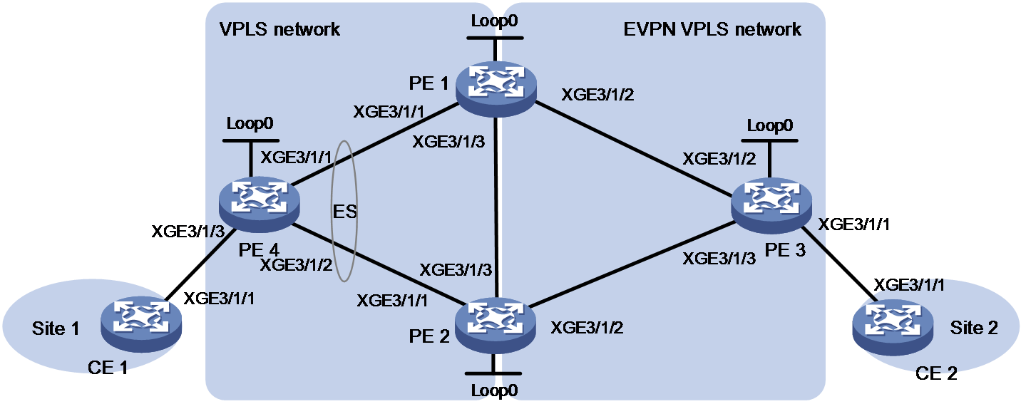
|
Device |
Interface |
IP address |
Device |
Interface |
IP address |
|
PE 1 |
Loop0 |
1.1.1.9/32 |
PE 3 |
Loop0 |
3.3.3.9/32 |
|
|
XGE3/1/1 |
10.1.1.1/24 |
|
XGE3/1/1 |
- |
|
|
XGE3/1/2 |
30.1.1.1/24 |
|
XGE3/1/2 |
30.1.1.3/24 |
|
|
XGE3/1/3 |
10.1.3.1/24 |
|
XGE3/1/3 |
10.1.2.3/24 |
|
PE 2 |
Loop0 |
2.2.2.9/32 |
PE 4 |
Loop0 |
4.4.4.9/32 |
|
|
XGE3/1/1 |
20.1.1.2/24 |
|
XGE3/1/3 |
- |
|
|
XGE3/1/2 |
10.1.2.2/24 |
|
XGE3/1/1 |
10.1.1.4/24 |
|
|
XGE3/1/3 |
10.1.3.2/24 |
|
XGE3/1/2 |
20.1.1.4/24 |
|
CE 1 |
XGE3/1/1 |
100.1.1.1/32 |
CE 2 |
XGE3/1/1 |
100.1.1.2/32 |
Procedure
1. Configure CE 1:
# Configure an IP address and mask for Ten-GigabitEthernet 3/1/1.
<CE1> system-view
[CE1] interface ten-gigabitethernet 3/1/1
[CE1-Ten-GigabitEthernet3/1/1] ip address 100.1.1.1 24
[CE1-Ten-GigabitEthernet3/1/1] quit
2. Configure PE 4:
# Configure MPLS basic capabilities.
<PE4> system-view
[PE4] interface loopback 0
[PE4-LoopBack0] ip address 1.1.1.9 32
[PE4-LoopBack0] quit
[PE4] mpls lsr-id 1.1.1.9
# Enable LDP globally.
[PE4] mpls ldp
[PE4-ldp] quit
# Enable L2VPN.
[PE4] l2vpn enable
# Configure Ten-GigabitEthernet 3/1/1, the interface connected to PE 1.
[PE4] interface ten-gigabitethernet 3/1/1
[PE4-Ten-GigabitEthernet3/1/1] ip address 10.1.1.4 24
[PE4-Ten-GigabitEthernet3/1/1] ospf 1 area 0
[PE4-Ten-GigabitEthernet3/1/1] mpls enable
[PE4-Ten-GigabitEthernet3/1/1] mpls ldp enable
[PE4-Ten-GigabitEthernet3/1/1] undo shutdown
[PE4-Ten-GigabitEthernet3/1/1] quit
# Configure Ten-GigabitEthernet 3/1/2, the interface connected to PE 2.
[PE4] interface ten-gigabitethernet 3/1/2
[PE4-Ten-GigabitEthernet3/1/2] ip address 20.1.1.4 24
[PE4-Ten-GigabitEthernet3/1/2] ospf 1 area 0
[PE4-Ten-GigabitEthernet3/1/2] mpls enable
[PE4-Ten-GigabitEthernet3/1/2] mpls ldp enable
[PE4-Ten-GigabitEthernet3/1/2] undo shutdown
[PE4-Ten-GigabitEthernet3/1/2] quit
# Configure VSI vpna to use LDP to establish LDP PWs. The LDP PW between PE 1 and PE 4 is the primary PW and the LDP PW between PE 2 and PE 4 is the backup PW. Enable the dual receive feature for PW redundancy.
[PE4] vsi vpna
[PE4-vsi-vpna] protection dual-receive
[PE4-vsi-vpna] pwsignaling ldp
[PE4-vsi-vpna-ldp] peer 1.1.1.9 pw-id 500
[PE4-vsi-vpna-ldp-1.1.1.9-500] backup-peer 2.2.2.9 pw-id 500
[PE4-vsi-vpna-ldp-1.1.1.9-500-backup] quit
[PE4-vsi-vpna-ldp-1.1.1.9-500] quit
[PE4-vsi-vpna-ldp] quit
[PE4-vsi-vpna] quit
# Map Ten-GigabitEthernet 3/1/3 to VSI vpna.
[PE4] interface ten-gigabitethernet 3/1/3
[PE4-Ten-GigabitEthernet3/1/3] xconnect vsi vpna
[PE4-Ten-GigabitEthernet3/1/3] quit
3. Configure PE 1:
# Configure interface Loopback 0.
<PE1> system-view
[PE1] interface loopback 0
[PE1-LoopBack1] ip address 1.1.1.9 32
[PE1-LoopBack1] quit
# Configure MPLS basic capabilities.
[PE1] mpls lsr-id 1.1.1.9
# Enable LDP globally.
[PE1] mpls ldp
[PE1-ldp] quit
# Enable L2VPN.
[PE1] l2vpn enable
# Run OSPF on PE 1 to set up LSPs.
[PE1] ospf
[PE1-ospf-1] area 0
[PE1-ospf-1-area-0.0.0.0] network 10.1.1.0 0.0.0.255
[PE1-ospf-1-area-0.0.0.0] network 30.1.1.0 0.0.0.255
[PE1-ospf-1-area-0.0.0.0] network 10.1.3.0 0.0.0.255
[PE1-ospf-1-area-0.0.0.0] network 1.1.1.9 0.0.0.0
[PE1-ospf-1] quit
# Configure Ten-GigabitEthernet 3/1/1, the interface connected to PE 4.
[PE1] interface ten-gigabitethernet 3/1/1
[PE1-Ten-GigabitEthernet3/1/1] ip address 10.1.1.1 24
[PE1-Ten-GigabitEthernet3/1/1] mpls enable
[PE1-Ten-GigabitEthernet3/1/1] mpls ldp enable
[PE1-Ten-GigabitEthernet3/1/1] undo shutdown
[PE1-Ten-GigabitEthernet3/1/1] quit
# Configure Ten-GigabitEthernet 3/1/2, the interface connected to PE 3.
[PE1] interface ten-gigabitethernet 3/1/2
[PE1-Ten-GigabitEthernet3/1/2] ip address 30.1.1.1 24
[PE1-Ten-GigabitEthernet3/1/2] mpls enable
[PE1-Ten-GigabitEthernet3/1/2] mpls ldp enable
[PE1-Ten-GigabitEthernet3/1/2] undo shutdown
[PE1-Ten-GigabitEthernet3/1/2] quit
# ConfigureTen-GigabitEthernet 3/1/3, the interface connected to PE 2.
[PE1] interface ten-gigabitethernet 3/1/3
[PE1-Ten-GigabitEthernet3/1/3] ip address 10.1.3.1 24
[PE1-Ten-GigabitEthernet3/1/3] mpls enable
[PE1-Ten-GigabitEthernet3/1/3] mpls ldp enable
[PE1-Ten-GigabitEthernet3/1/3] undo shutdown
[PE1-Ten-GigabitEthernet3/1/3] quit
# Establish IBGP connections to PE 2 and PE 3, and enable BGP EVPN to advertise route information to PE 2 and PE 3.
[PE1] bgp 100
[PE1-bgp-default] peer 2.2.2.9 as-number 100
[PE1-bgp-default] peer 2.2.2.9 connect-interface loopback 0
[PE1-bgp-default] peer 3.3.3.9 as-number 100
[PE1-bgp-default] peer 3.3.3.9 connect-interface loopback 0
[PE1-bgp-default] address-family l2vpn evpn
[PE1-bgp-default-evpn] peer 2.2.2.9 enable
[PE1-bgp-default-evpn] peer 3.3.3.9 enable
[PE1-bgp-default-evpn] peer 2.2.2.9 advertise encap-type mpls
[PE1-bgp-default-evpn] peer 3.3.3.9 advertise encap-type mpls
[PE1-bgp-default-evpn] quit
[PE1-bgp-default] quit
# Create a PW class and set its data encapsulation type to Ethernet.
[PE1] pw-class aaa
[PE1-pw-class-aaa] pw-type ethernet
[PE1-pw-class-aaa] quit
# Create VSI vpna, create an EVPN instance for it, enable MPLS encapsulation, and configure an RD and route targets for the EVPN instance.
[PE1] vsi vpna
[PE1-vsi-vpna] evpn encapsulation mpls
[PE1-vsi-vpna-evpn-srv6] route-distinguisher 1:1
[PE1-vsi-vpna-evpn-srv6] vpn-target 1:1 export-extcommunity
[PE1-vsi-vpna-evpn-srv6] vpn-target 1:1 import-extcommunity
[PE1-vsi-vpna-evpn-srv6] quit
# Configure VSI vpna to use LDP to establish LDP PWs. Configure PE 1 to establish an UPW with PE 4, assign an ESI to the UPW, and set the redundancy mode of the UPW to all-active.
[PE1-vsi-vpna] pwsignaling ldp
[PE1-vsi-vpna-ldp] peer 4.4.4.9 pw-id 500 no-split-horizon pw-class aaa
[PE1-vsi-vpna-ldp-4.4.4.9-500] esi 1.1.1.1.1
[PE1-vsi-vpna-ldp-4.4.4.9-500] evpn redundancy-mode all-active
[PE1-vsi-vpna-ldp-4.4.4.9-500] quit
[PE1-vsi-vpna-ldp] quit
[PE1-vsi-vpna] quit
4. Configure PE 2:
# Configure MPLS basic capabilities.
<PE2> system-view
[PE2] interface loopback 0
[PE2-LoopBack0] ip address 2.2.2.9 32
[PE2-LoopBack0] quit
[PE2] mpls lsr-id 2.2.2.9
# Enable LDP globally.
[PE2] mpls ldp
[PE2-ldp] quit
# Enable L2VPN.
[PE2] l2vpn enable
# Run OSPF on PE 2 to set up LSPs.
[PE2] ospf
[PE2-ospf-1] area 0
[PE2-ospf-1-area-0.0.0.0] network 10.1.2.0 0.0.0.255
[PE2-ospf-1-area-0.0.0.0] network 20.1.1.0 0.0.0.255
[PE2-ospf-1-area-0.0.0.0] network 10.1.3.0 0.0.0.255
[PE2-ospf-1-area-0.0.0.0] network 2.2.2.9 0.0.0.0
[PE2-ospf-1] quit
# Configure Ten-GigabitEthernet 3/1/3, the interface connected to PE 1.
[PE2] interface ten-gigabitethernet 3/1/3
[PE2-Ten-GigabitEthernet3/1/3] ip address 10.1.3.2 24
[PE2-Ten-GigabitEthernet3/1/3] mpls enable
[PE2-Ten-GigabitEthernet3/1/3] mpls ldp enable
[PE2-Ten-GigabitEthernet3/1/3] undo shutdown
[PE2-Ten-GigabitEthernet3/1/3] quit
# Configure Ten-GigabitEthernet 3/1/2, the interface connected to PE 3.
[PE2] interface ten-gigabitethernet 3/1/2
[PE2-Ten-GigabitEthernet3/1/2] ip address 10.1.2.1 24
[PE2-Ten-GigabitEthernet3/1/2] mpls enable
[PE2-Ten-GigabitEthernet3/1/2] mpls ldp enable
[PE2-Ten-GigabitEthernet3/1/2] undo shutdown
[PE2-Ten-GigabitEthernet3/1/2] quit
# Configure Ten-GigabitEthernet 3/1/1, the interface connected to PE 4.
[PE2] interface ten-gigabitethernet 3/1/1
[PE2-Ten-GigabitEthernet3/1/1] ip address 20.1.1.2 24
[PE2-Ten-GigabitEthernet3/1/1] mpls enable
[PE2-Ten-GigabitEthernet3/1/1] mpls ldp enable
[PE2-Ten-GigabitEthernet3/1/1] undo shutdown
[PE2-Ten-GigabitEthernet3/1/1] quit
# Establish IBGP connections to PE 1 and PE 3 and enable BGP EVPN to advertise route information to PE 1 and PE 3.
[PE2] bgp 100
[PE2-bgp-default] peer 1.1.1.9 as-number 100
[PE2-bgp-default] peer 1.1.1.9 connect-interface loopback 0
[PE2-bgp-default] peer 3.3.3.9 as-number 100
[PE2-bgp-default] peer 3.3.3.9 connect-interface loopback 0
[PE2-bgp-default] address-family l2vpn evpn
[PE2-bgp-default-evpn] peer 1.1.1.9 enable
[PE2-bgp-default-evpn] peer 3.3.3.9 enable
[PE2-bgp-default-evpn] peer 1.1.1.9 advertise encap-type mpls
[PE2-bgp-default-evpn] peer 3.3.3.9 advertise encap-type mpls
[PE2-bgp-default-evpn] quit
[PE2-bgp-default] quit
# Create a PW class and set its data encapsulation type to Ethernet.
[PE2] pw-class aaa
[PE2-pw-class-aaa] pw-type ethernet
[PE2-pw-class-aaa] quit
# Create VSI vpna, create an EVPN instance for it, enable MPLS encapsulation, and configure an RD and route targets for the EVPN instance.
[PE2] vsi vpna
[PE2-vsi-vpna] evpn encapsulation mpls
[PE2-vsi-vpna-evpn-srv6] route-distinguisher 1:1
[PE2-vsi-vpna-evpn-srv6] vpn-target 1:1 export-extcommunity
[PE2-vsi-vpna-evpn-srv6] vpn-target 1:1 import-extcommunity
[PE2-vsi-vpna-evpn-srv6] quit
# Configure VSI vpna to use LDP to establish LDP PWs. Configure PE 2 to establish an UPW with PE 4, assign an ESI to the UPW, and set the redundancy mode of the UPW to all-active.
[PE2] vsi vpna
[PE2-vsi-vpna] pwsignaling ldp
[PE2-vsi-vpna-ldp] peer 1.1.1.9 pw-id 500 no-split-horizon pw-class aaa
[PE2-vsi-vpna-ldp-1.1.1.9-500] esi 1.1.1.1.1
[PE2-vsi-vpna-ldp-1.1.1.9-500] evpn redundancy-mode all-active
[PE2-vsi-vpna-ldp-1.1.1.9-500] quit
[PE2-vsi-vpna-ldp] quit
[PE2-vsi-vpna] quit
5. Configure PE 3:
# Configure MPLS basic capabilities.
<PE3> system-view
[PE3] interface loopback 0
[PE3-LoopBack0] ip address 3.3.3.9 32
[PE3-LoopBack0] quit
[PE1] mpls lsr-id 3.3.3.9
# Enable LDP globally.
[PE1] mpls ldp
[PE1-ldp] quit
# Enable L2VPN.
[PE3] l2vpn enable
# Run OSPF on PE 3 to set up LSPs.
[PE3] ospf
[PE3-ospf-1] area 0
[PE3-ospf-1-area-0.0.0.0] network 10.1.2.0 0.0.0.255
[PE3-ospf-1-area-0.0.0.0] network 30.1.1.0 0.0.0.255
[PE3-ospf-1-area-0.0.0.0] network 3.3.3.9 0.0.0.0
[PE3-ospf-1] quit
# Configure Ten-GigabitEthernet 3/1/2, the interface connected to PE 1.
[PE3] interface ten-gigabitethernet 3/1/2
[PE3-Ten-GigabitEthernet3/1/2] ip address 30.1.1.3 24
[PE3-Ten-GigabitEthernet3/1/2] undo shutdown
[PE3-Ten-GigabitEthernet3/1/2] quit
# Configure Ten-GigabitEthernet 3/1/3, the interface connected to PE 2.
[PE3] interface ten-gigabitethernet 3/1/3
[PE3-Ten-GigabitEthernet3/1/3] ip address 10.1.2.3 24
[PE3-Ten-GigabitEthernet3/1/3] undo shutdown
[PE3-Ten-GigabitEthernet3/1/3] quit
# Establish IBGP connections to PE 1 and PE 2, and enable BGP EVPN to advertise route information to PE 1 and PE 2.
[PE3] bgp 100
[PE3-bgp-default] peer 1.1.1.9 as-number 100
[PE3-bgp-default] peer 1.1.1.9 connect-interface loopback 0
[PE3-bgp-default] peer 2.2.2.9 as-number 100
[PE3-bgp-default] peer 2.2.2.9 connect-interface loopback 0
[PE3-bgp-default] address-family l2vpn evpn
[PE3-bgp-default-evpn] peer 1.1.1.9 enable
[PE3-bgp-default-evpn] peer 2.2.2.9 enable
[PE3-bgp-default-evpn] peer 1.1.1.9 advertise encap-type mpls
[PE3-bgp-default-evpn] peer 2.2.2.9 advertise encap-type mpls
[PE3-bgp-default-evpn] quit
[PE3-bgp-default] quit
# Create VSI vpna, create an EVPN instance for it, enable MPLS encapsulation, and configure an RD and route targets for the EVPN instance.
[PE3] vsi vpna
[PE3-vsi-vpna] evpn encapsulation mpls
[PE3-vsi-vpna-evpn-srv6] route-distinguisher 1:1
[PE3-vsi-vpna-evpn-srv6] vpn-target 1:1 export-extcommunity
[PE3-vsi-vpna-evpn-srv6] vpn-target 1:1 import-extcommunity
[PE3-vsi-vpna-evpn-srv6] quit
# Map Ten-GigabitEthernet 3/1/1 to VSI vpna.
[PE3] interface ten-gigabitethernet 3/1/1
[PE3-Ten-GigabitEthernet3/1/1] xconnect vsi vpna
[PE3-Ten-GigabitEthernet3/1/1] quit
6. Configure CE 2.
<CE2> system-view
[CE2] interface ten-gigabitethernet 3/1/1
[CE2-Ten-GigabitEthernet3/1/1] ip address 100.1.1.2 24
[CE2-Ten-GigabitEthernet3/1/1] quit
Verifying the configuration
# On PE 1, display PW information. Verify that PE 1 has established an LDP PW with PE 4 and EVPN PWs with PE 2 and PE 3.
<PE1> display l2vpn pw
Flags: M - main, B - backup, E - ecmp, BY - bypass, H - hub link, S - spoke link
N - no split horizon, A - administration, ABY - ac-bypass
PBY - pw-bypass
Total number of PWs: 3
3 up, 0 blocked, 0 down, 0 defect, 0 idle, 0 duplicate
VSI Name: vpna
Peer PWID/RmtSite/SrvID In/Out Label Proto Flag Link ID State
4.4.4.9 500 1147/- LDP MN 8 Up
2.2.2.9 - 1148/1148 EVPN M 9 Up
3.3.3.9 - 1148/1149 EVPN M 10 Up
# On PE 1, display local ES information. Verify that the LDP PW (UPW) has multihoming settings.
<PE1> display evpn es local verbose
VSI name : vpna
ESI : 0001.0001.0001.0001.0001
Interface : -
Redundancy mode : All-active
State : Up
UPWs :
Link ID Service instance ID Tag ID DF address ESI label
8 - 0 - 1146
# Display information on PE 2 in the same way as information is displayed on PE 1. (Details not shown.)
# Verify that CE 1 and CE 2 can ping each other. (Details not shown.)
