- Table of Contents
-
- H3C Servers UniSystem Configuration Examples-6W100
- 01-UniSystem Bulk HDM&BIOS Import Configuration Examples
- 02-H3C UniSystem Cloning Installation Configuration Examples
- 03-UniSystem SMTP Configuration Examples
- 04-H3C UniSystem Cluster Creation Configuration Examples
- 05-H3C UniSystem SNMP Configuration Examples
- 06-H3C UniSystem RAID Configuration Examples
- 07-H3C UniSystem Rack Server Deployment Configuration Examples
- 08-UniSystem Bulk Component Update Configuration Examples
- Related Documents
-
| Title | Size | Download |
|---|---|---|
| 06-H3C UniSystem RAID Configuration Examples | 868.38 KB |
H3C UniSystem
RAID Configuration Examples
Copyright © 2023 New H3C Technologies Co., Ltd. All rights reserved.
No part of this manual may be reproduced or transmitted in any form or by any means without prior written consent of New H3C Technologies Co., Ltd.
Except for the trademarks of New H3C Technologies Co., Ltd., any trademarks that may be mentioned in this document are the property of their respective owners.
The information in this document is subject to change without notice.
Introduction
The following information describes the typical configuration of the Redundant Array of Independent Disks (RAID) feature of UniSystem.
When you configure the RAID feature for multiple servers, it is cumbersome and inefficient to configure each server separately. To batch configure the RAID feature, you can configure RAID in the UniSystem server template and then apply the template to the target servers.
|
|
NOTE: Starting from version 2.59, FIST software has been renamed as UniSystem. |
Prerequisites
Procedures and information in the examples might be slightly different depending on the software or hardware version of the devices.
The configuration was created and verified in a lab environment, and all the servers and software were started with the factory default configuration. When you are working on a live network, make sure you understand the potential impact of every command on your network.
The following information is provided based on the assumption that you have basic knowledge of UniSystem and RAID feature.
Restrictions and cautions
· Make sure that the device model and the hardware configuration in the server template are the same as that on the target server.
· The storage controllers must be the same model. If two RAID cards are installed, make sure that the storage controllers are inserted in the corresponding slots and are of the same model.
· Make sure the RAID member drives are present and operating properly.
· Power off the servers before applying a server template, as the operation will affect the system service.
· Before applying a server template, make sure that no other operations are in progress on the server to be configured.
Configuration example
Network requirement
As shown in Figure 1, Server A and Server B (H3C UniServer R4900 G5 is used as an example here) are connected to the PC running UniSystem through a switch and the networks are reachable. Configure the RAID feature through UniSystem in the server template. Prepare one storage controller for each server. RAID-LSI-9361-8i(2G)-1-X is used as an example here. Prepare 7 hard drives for each server, 3 of which for group RAID5 and 4 for group RAID10. Then apply the server template to Server A and Server B to batch configure the RAID feature quickly.
· UniSystem management software information:
¡ IP addresses: 172.15.88.39/17
¡ Administrator account: admin
¡ Administrator password: Password@_
· Information about the two servers is as follows:
¡ HDM management IP address of Server A: 172.15.104.68/17
¡ HDM management IP address of Server B: 172.15.93.83/17
Figure 1 Network diagram of UniSystem RAID configuration

Analysis
· To batch configure the RAID feature on Server A and Server B, you need to select the RAID configuration when creating the server template.
· Before applying the server template, shut down Server A and Server B first.
Software versions used
UniSystem 2.39 is used here as an example.
Procedures
Add the servers to UniSystem.
1. Open the browser of the UniSystem client, enter the system IP 172.15.88.39 of the UniSystem server in the address bar, and press Enter to navigate to the UniSystem login page, as shown in Figure 2.
2. On the login page, enter the username (admin by default) and password (Password@_ by default), and then click Log In.
Figure 2 UniSystem Web login page

3. Click Menu > Devices > Server List. On the server list page that opens, click Add. In the Method dialog box, select a server addition method, as shown in Figure 3.
Figure 3 Selecting the method of adding the server

4. Three methods are available. In this example, Add manually is selected. Click Add manually. In the dialog box that opens, add the server information of the two servers to be added, as shown in Figure 4.
Figure 4 Manually adding the server

· Device Type: Select HDM.
· IP Address: Specify the HDM IP address of the server to be added, which is 172.15.104.68.
· Username: Specify the HDM login username of the server to be added, which is admin.
· Password: Specify the HDM password of the server to be added, which is Password@_.
· Device Name: The device name displayed on UniSystem after the server is added, which can be left blank.
Add another server in the same way. The specific operation process is not described again.
|
|
NOTE: If more than three servers need to be added, select a method based on the actual requirements. |
Creating a server template
1. Click Menu > Templates > Server Templates to navigate to the page shown in Figure 5.

2. Click Add to create the server template, as shown in Figure 6.
Figure 6 Creating a server template

· Basic Info:
¡ Name: Name of the template.
¡ Description: Optional.
¡ Server Model: Select a model from the drop-down list. H3C UniServer R4900 G5 is used as an example here, so select H3C UniServer R4900 G5 here.
· Configuration options:
¡ Select whether to enable Retain Matching Logical Drives in the RAID Settings area. If you enable this option to retain a logical drive on a server, make sure the member drives and RAID level of the logical drive match those of a logical drive configured in this area. If you do not enable this option, UniSystem will delete the existing logical drives on a server.
|
|
NOTE: · After you enable Retain Matching Logical Drives, UniSystem will retain a logical drive on a server if the member drives and RAID level of the logical drive match those of a logical drive configured in this area. UniSystem will not modify the retained logical drives, even if the RAID name in the configuration file for a retained logical drive is different from the actual RAID name. · To install an operating system to a retained logical drive through system settings, make sure the RAID name of the target drive in the OS settings area is the same as the original RAID name of the retained logical drive. |
3. Click Add Storage Controller, as shown in Figure 7.
Figure 7 Adding a storage controller

4. Select Slot Number, Vendor Type, and Model, as shown in Figure 8.
Figure 8 Configuring RAID arrays

5. Click Configure. The page for configuring the storage controller opens, as shown in Figure 9.
Figure 9 Configuring a storage controller

6. Click Add Logical Drive and enter the RAID name RAID5. Select the RAID level RAID 5 and select three physical drives, as shown in Figure 10.

7. Click OK to complete the configuration of RAID5, as shown in Figure 11.

8. Click Add Logical Drive and enter the RAID name RAID10. Select the RAID level RAID 10 and select four physical drives, as shown in Figure 12.

9. Click OK to complete the configuration of RAID10, as shown in Figure 13.

10. After the configuration is completed, click OK to create the server template. After the server template is created, you can view the created template on the Server Templates page, as shown in Figure 14.

Applying a server template
1. Click Menu > Server Deployment > Apply Server Templates, as shown in Figure 15.
Figure 15 Page for applying a server template

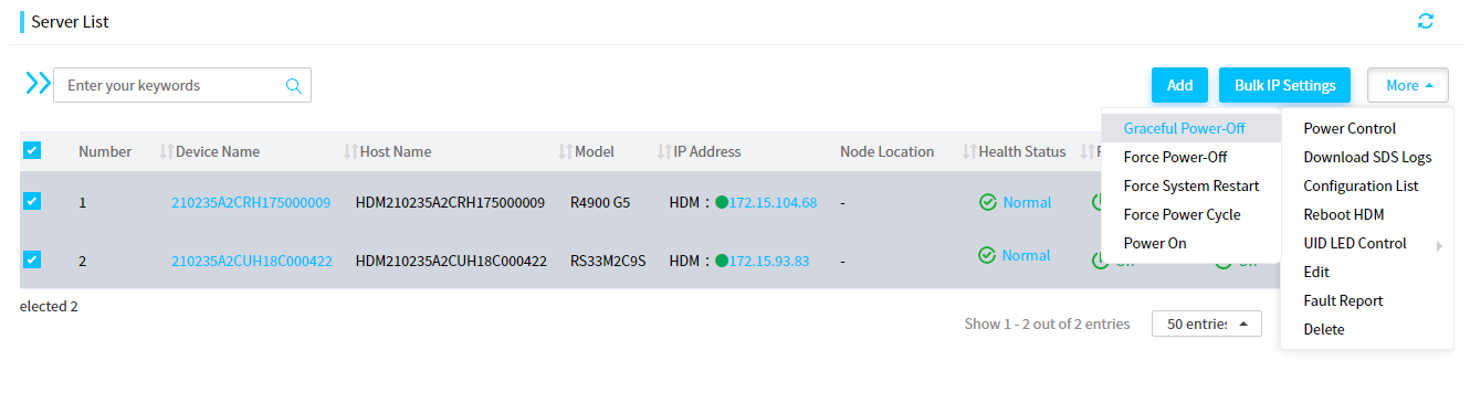
2. Before applying a server template, power off the servers. Click Menu > Servers > Server List. Check the servers you want to shut down. Click More > Power Control > Graceful Power-Off, as shown in Figure 16.
Figure 16 Powering off the servers
3. In the Power Control dialog box, check the server list. Click OK, as shown in Figure 17.

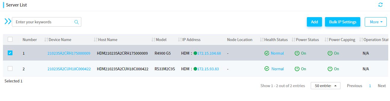
4. Navigate to the Apply Server Template page, check the servers with IP addresses of 172.15.104.68 and 172.15.93.83. Then click Apply Server Template, as shown in Figure 18.
Figure 18 Applying a server template

5. The dialog box for applying server templates opens. In the drop-down box of Server Template, select the server template that you want to apply. Select I have read the template application-related restrictions and guidelines, and then click OK, as shown in Figure 19.
Figure 19 Confirming the server template application

6. After a sever template is applied, you can view the application results on the application status page, as shown in Figure 20.
Figure 20 Sever template applied

Verifying configuration
1. Click the menu, select the server list, and then select a server, as shown in Figure 21.
2. Click the link beside the device name to navigate to the server details page, as shown in Figure 22.

3. Select the Hardware Details tab, as shown in Figure 23.
Figure 23 Hardware details page

4. Select Storage Info. Then you can view the two logical drives (RAID5 and RAID10) and their member drives. The information is the same as that in the server template, indicating that the configuration is successful.
View the RAID logical drive information on another server similarly. The information is the same as that in the server template, indicating that the configuration is successful. The specific operation process is not described again.
Related documentation
· H3C Servers UniSystem User Guide
· H3C Servers Storage Controller User Guide
