- Table of Contents
- Related Documents
-
| Title | Size | Download |
|---|---|---|
| 03-H3C Wireless Client Packet Loss Troubleshooting Guide | 115.30 KB |
H3C Wireless Client Packet Loss
Troubleshooting Guide
Copyright © 2023 New H3C Technologies Co., Ltd. All rights reserved
No part of this manual may be reproduced or transmitted in any form or by any means without prior written consent of New H3C Technologies Co., Ltd.
The information in this document is subject to change without notice.
Contents
Testing the packet loss ratio of the wireless client
Checking the wired network that connects the AC and the AP
Troubleshooting wireless access
Checking the online state of the wireless client
Eliminating radio interference and reducing background noise
Collecting client packet capture, radio packet capture, and debugging information
Logging in to the AP to enable debugging
Introduction
In a WLAN, a wireless client sometimes experience continuous packet loss when it pings other devices. This might be accompanied by increasing ping latency (hundreds of milliseconds), slower download speed, and video jitter, resulting in poor experience for wireless client users. Such an issue is challenging for the WLAN network. On one hand, the spatial medium used by the WLAN network is complex and difficult to evaluate, causing air interface instability. On the other hand, it is necessary to comprehensively consider the configuration and performance of the entire wired and wireless network.
Troubleshooting analysis
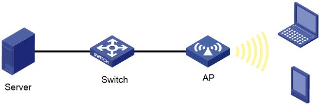
As shown in Figure 1, in a typical WLAN, if a wireless client experiences severe packet loss when it pings the server, troubleshoot the issue based on the packet forwarding path.
Figure 1 AC + fit AP network diagram
The troubleshooting analysis is as follows:
1. Test the packet loss ratio of the wireless client.
2. Identify whether the wired network that connects the AC and the AP has a packet loss issue.
3. Identify whether the wireless client can access the network and obtain an IP address.
4. Check the wireless client state, air interface usage, air interface quality, and background noise.
5. Collect debugging information to analyze the issue cause.
Troubleshooting procedures
Testing the packet loss ratio of the wireless client
Identify whether the packet loss on the network is random or regular by performing a ping operation.
Based on the current protocol analysis and practical application, wireless networks cannot really achieve zero packet loss. When the air interface usage is normal and no interference exists, an irregular packet loss ratio of less than 3% is acceptable.
For example,
D:\>Ping 192.168.1.3
Pinging 192.168.1.3 with 32 bytes of data:
Reply from 192.168.1.3: bytes=32 time=19ms TTL=255
Reply from 192.168.1.3: bytes=32 time=4ms TTL=255
Reply from 192.168.1.3: bytes=32 time=3ms TTL=255
Reply from 192.168.1.3: bytes=32 time=4ms TTL=255
Ping statistics for 192.168.1.3:
Packets: Sent = 4, Received = 4, Lost = 0 (0% loss),
Approximate round trip times in milli-seconds:
Minimum = 3ms, Maximum = 19ms, Average = 7ms
Checking the wired network that connects the AC and the AP
1. If the AC does not operate as a gateway, ping the IP address of the AC on the wireless client.
If you can ping the AC but fail to ping the gateway, check the Layer 2 network between the AC and the gateway.
If you fail to ping both the gateway and the AC, troubleshoot packet loss on the wired network.
2. If the wireless client is online, perform the following tasks:
a. Execute the display wlan client command to obtain the name of the AP to which the wireless client is connected from the AP name field.
b. Execute the display wlan ap command to obtain the IP address of the AP to which the wireless client is connected.
For example, the following command output shows that the IP address of AP ap1 is 192.168.1.6, and the uptime is about 22 hours. If the uptime is too short, it indicates that an AP registration error may have occurred.
[AC]display wlan ap name ap1 verbose
…
Up Time(hh:mm:ss) : 22:06:21
…
IP Address : 192.168.1.6
c. Ping the IP address of the AP on the AC and observe the network quality. Identify whether the wired network between the AC and the AP is normal.
3. If the wireless client is offline, troubleshoot packet loss on the wired network.
a. Identify the packet loss location by performing layer-by-layer ping operations and capturing packets.
b. Identify whether the network configuration at Layer 2 and Layer 3 complies with specifications.
Troubleshooting wireless access
1. Check the wireless client configuration.
¡ Verify that the NIC on the wireless client is enabled.
¡ Verify that the wireless service is enabled. For example, in a Windows operating system, make sure the Wireless Zero Configuration service is enabled.
¡ Verify that the wireless client is operating in the wireless client mode correctly. If you configure it to operate in the AP mode, it cannot be used as a wireless client.
¡ Verify that the wireless client is associated with the correct SSID.
2. Execute the display wlan client command on the AC to verify that the wireless client is associated with the AP.
Troubleshooting DHCP
On the wireless client, verify that the client has obtained a correct IP address. For example, if the client is a PC, open cmd and execute the ipconfig/all command. If the client is a mobile phone or pad, check the network status to view the IP address obtaining status.
Checking the online state of the wireless client
Execute the display wlan client verbose command to verify that the wireless client has come online correctly.
For example,
[AC] display wlan client mac-address 0024-d79c-af4c verbose
Total number of clients: 1
MAC address : 000f-e265-6400
…
SM power save : Enabled
…
RSSI : 62
Rx/Tx rate : 130/195 Mbps
…
Online time : 0days 0hours 1minutes 13seconds
· SM power save—SM power save state of the wireless client. When the wireless client is in sleep state, the ping latency is high, which is typically greater than the beacon interval.
· RSSI—Wireless client signal strength received by the AP, which should be greater than 30. If the received signal strength indication (RSSI) of the wireless user is lower than 25, analyze its impact on the entire network and the user state. To increase the RSSI, you can adjust the antenna or increase the number of APs to optimize signal coverage.
· Rx/Tx Rate—If the Rx rate remains low (for example, 1, 2, or 11 Mbps), the air interface environment is not very good or even has severe packet loss. You must check the channel occupancy and network traffic for the air interface and perform traffic control or rate limit for wireless users as required.
· Online time—Online time of the client. If the online time is short, but the client has used the wireless network for a long time, identify whether the client has roamed. You can adjust the transmission power of the AP to which the client is connected to reduce client roamings, or lower the roaming initiative of the NIC.
Checking the radio usage
1. Execute the display wlan client command to obtain the name of the AP to which the wireless client is connected from the AP name field.
2. Execute the display wlan ap command to obtain the IP address of the AP to which the wireless client is connected.
3. Execute the wlan ap-execute ap-name exec-control enable command in probe view to enable remote login for the fit AP.
4. Log in to the AC through Telnet, and then log in to the fit AP associated with the wireless client. The login password is h3capadmin.
5. Execute the display ar5drv radio channelbusy command to view the channel usage and check the radio busyness.
The radio argument represents the radio ID. A single-band AP has only one radio interface. A dual-band AP has two radio interfaces, and radio 1 represents the 5 GHz radio and radio 2 represents the 2.4 GHz radio.
For example, the following command output shows that the 5 GHz radio of the AP is in normal state. The radio is busy if the value of the CtlBusy field is higher than 60.
System View: return to User View with Ctrl+Z.
[AP] probe
[AP-probe] display ar5drv 1 channelbusy
ChannelBusy information
Ctl Channel: 149 Channel Band: 40M
Ext Channel: Above
Record Interval(s): 9
Date/Month/Year: 03/05/2019
Time(h/m/s): CtlBusy(%) TxBusy(%) RxBusy(%) ExtBusy(%)
01 11:18:35 68 37 28 0
02 11:18:26 67 36 29 0
03 11:18:17 63 35 26 0
04 11:18:08 78 40 33 0
05 11:17:59 81 43 36 0
...
6. Execute the display ar5drv radio statistics command to view the AP radio statistics and check the channel quality.
The radio argument represents the radio ID. A single-band AP has only one radio interface. A dual-band AP has two radio interfaces, and radio 1 represents the 5 GHz radio and radio 2 represents the 2.4 GHz radio.
[AP-probe] display ar5drv 1 statistics
RxResetTgtChipCnts : 0
Radio statistics:
TxFrameAllCnt : 40693
TxFrameAllBytes : 7293360
Queue statistics
Queue Number :0 1 2 3 Mgmt EmergencyQ CAB
----------------------------------------------------------------
TxFrmCnt :152 5745 0 0 1883 2729 0
TxUcastFrmCnt:152 3780 0 0 1883 0 0
...
TxDiscardFrm :2 4 0 0 31 2 0
...
RadioResetOnErr : 0
...
BeaconBusyCnt : 2
BeaconErrCnt : 0
...
¡ Each radio has four regular transmission queues and one emergency transmission queue. Typically, data packets go through queue 1, and extra attention is required for queue 1.
¡ TxDiscardFrm—Total number of discarded packets in this queue, including packets that failed to be sent and overflow packets.
¡ TxFrmCnt/TxUcastFrmCnt—Packet loss rate. Pay attention if the packet loss rate exceeds 3%.
¡ RadioResetOnErr—Number of times that the radio chip reset causes packet loss. This error does not occur under normal circumstances.
¡ BeaconBusyCnt and BeaconErrCnt—Busyness and error statistics about beacon packet transmission for the AP. You can use these two fields to identify the air interface quality. Packet loss occurs when the value for a field increases.
Eliminating radio interference and reducing background noise
1. Check the background noise on the AP.
Execute the display ar5drv radio calibration command to view background noise information. If the value of the NF Value field is higher than –80, use instruments to analyze the cause.
[AP-probe] display ar5drv 1 calibration
Calibration Information:
Calibration Enable: YES
Calibration Interval: 1000 Reset Radio Count: 0
iqCalState: CAL_DONE I: 62/60/58, Q: -4/0/-2
iqCalValid: True
NoiseFloor: -93
CCA Info:
5GMaxCca: -50
5GMinCca: -122
5GNormCca: -112
NF Record:
Num: NF Value time
0 -93 17:54:43:038 10/05/2019
1 -93 17:54:44:038 10/05/2019
2 -93 17:54:45:038 10/05/2019
2. Use an instrument to analyze the issue.
You can use a Yellowjacket gauge. Yellowjacket gauges in IEEE 802.11b/g or a later version support checking and identifying the AP and RSSI signal levels and full-spectrum scanning. Alternatively, you can use a spectrum analyzer in spectrum mode to perform spectrum and interference analysis on test points.
Collecting client packet capture, radio packet capture, and debugging information
If the wireless client supports packet capture, radio packet capture is not required. To explain or prove an issue, capture packets on the radio. If the wireless client does not support packet capture, radio packet capture is required.
Capturing packets on a wireless client
As a best practice, use Wireshark or Ethereal to capture packets on the wireless client. When you capture packets on the wireless client, follow these restrictions and guidelines:
· To facilitate packet capture analysis, you can ping fixed-length packets on the wireless client, such as packets with a length of 130 bytes.
· When you provide the packet capture information, you must also provide the MAC and IP addresses of the wireless client.
· During packet analysis, identify whether each ping request is quickly responded based on the packet length.
· If you capture packets on both the wireless client and the radio, use sequence numbers to match the ping packets, and compare the packet capture time to identify the ping latency and packet loss.
· Use Ethereal to capture packets on a wireless laptop.
Capturing packets on a radio
You can use Omnipeek or Airmagnet to capture packets on a radio. When you capture packets on a radio, follow these restrictions and guidelines:
· The packet capture tool cannot capture all packets on the radio. You must fully consider the possibility that some packets may not be captured during analysis.
· No matter which packet capture tool is used, you must select the channel where the wireless client resides to perform packet capture.
· Ping packets include ping requests sent from the wireless client to the AP, and ping replies sent from the AP to the wireless client.
· To facilitate packet capture analysis, you can ping fixed-length packets on the wireless client, such as packets with a length of 130 bytes. You must ping fixed-length packets for a client that uses encrypted access.
Analyzing packet capture results
· Packet retransmission occurs when the wireless client does not send an ACK message or the AP does not receive an ACK message from the wireless client.
· The default number of retransmission attempts for the AP is 5. The number of retransmission attempts for the wireless client varies by wireless client model.
· If multiple identical retransmission packets consecutively appear among the captured packets but no ACK message exists, the corresponding packet may be lost.
· Identify whether packet loss occurs on the path from the AP to the wireless client or from the wireless client to the AP based on packet MAC addresses.
Logging in to the AP to enable debugging
1. Execute the display wlan client command to obtain the name of the AP to which the wireless client is connected from the AP name field.
2. Execute the display wlan ap command to obtain the IP address of the AP to which the wireless client is connected.
3. Execute the wlan ap-execute ap-name exec-control enable command in probe view to enable remote login for the fit AP.
4. Log in to the AC through Telnet, and then log in to the fit AP associated with the wireless client. The login password is h3capadmin.
5. On the fit AP, execute the debugging ar5drv radio phy packet all command in probe view, and then execute the terminal monitor and terminal debugging commands in user view.
|
|
IMPORTANT: Before you enable debugging, continuously ping the gateway on the wireless client. Check the CPU usage and memory usage to make sure enabling debugging will not affect the normal operation of the device. Disable debugging immediately after you collect the required information. |
