- Table of Contents
-
- 07-Segment Routing Configuration Guide
- 00-Preface
- 01-SR-MPLS configuration
- 02-SRv6 configuration
- 03-SRv6 TE policy configuration
- 04-SRv6 VPN overview
- 05-IP L3VPN over SRv6 configuration
- 06-EVPN L3VPN over SRv6 configuration
- 07-EVPN VPWS over SRv6 configuration
- 08-Public network IP over SRv6 configuration
- 09-SRv6 OAM configuration
- Related Documents
-
| Title | Size | Download |
|---|---|---|
| 09-SRv6 OAM configuration | 209.47 KB |
Contents
Restrictions and guidelines: SRv6 OAM configuration
Performing an SRv6 SID-based ping operation
Performing an SRv6 SID-based tracert operation
Performing an SRv6 TE policy-based ping operation
Performing an SRv6 TE policy-based tracert operation
Specifying a remote End.OP SID locator
Verifying link connectivity between a PE and a CE by using ping-ce
Configuring the sender MAC address range
Performing ping-ce to verify link connectivity between a PE and a CE
Configuring SRv6 OAM
About SRv6 OAM
SRv6 OAM methods
SRv6 OAM supports the following detection methods:
· SRv6 SID-based ping/tracert—Detects network connectivity and host reachability.
· SRv6 TE policy-based ping/tracert—Detects network connectivity and locates network problems.
· Ping-ce—Detects link connectivity between a PE and a CE in EVPN VPWS over SRv6 networks.
SRv6 SID-based ping and SRv6 TE policy-based ping are H3C proprietary protocols.
SRv6 OAM protocol extensions
OAM O-flag
As shown in Figure 1, the O-flag is in the SRH Flags field, indicating that the SRv6 nodes need to perform OAM processing. The SRv6 nodes process the packets with O-flag set based on the SRH. In SRv6 OAM, to request all SRv6 nodes on the path to respond to OAM packets, make sure the O-flag is set for the OAM packets at the source node.
Figure 1 O-flag in SRH Flags field
![]()
End.OP SID
An End.OP SID is an SRv6 SID of OAM type used in SRv6 SID/SRv6 TE policy-based ping/tracert operations. When a device receives a request packet destined for the local End.OP SID, it further checks the SRv6 SID in the packet. If the SRv6 SID is the local SRv6 SID, the device sends a reply; if not, the device discards the packet.
In ping or tracer operations based on SRv6 SID or SRv6 TE policy, packets can be used to detect SRv6 path connectivity, regardless of whether they carry the End.OP SIDs.
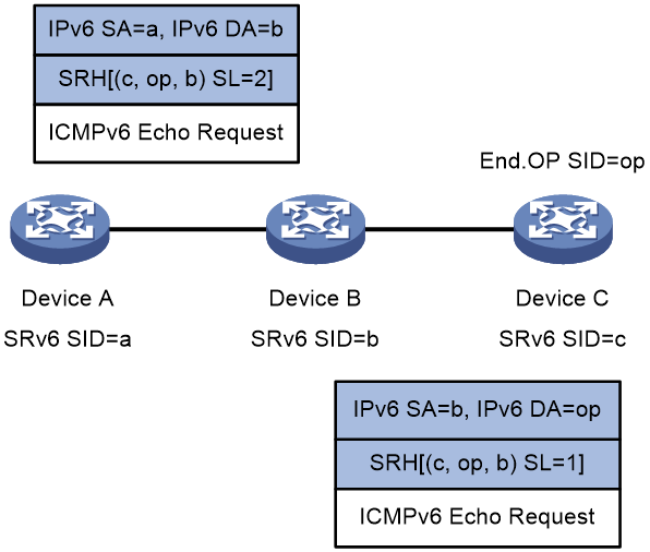
Take SRv6 SID-based ping as an example. As shown in Figure 2, in order to ping Device C, Device A constructs an ICMPv6 echo request by adding the End.OP SID of Device C to the SRH header in the request. Upon receiving the request and finding that request is destined for the local End.OP SID, Device C further checks whether SRv6 SID c is the local SRv6 SID. If it is the local SRv6 SID, Device C sends an ICMPv6 echo reply; if not, Device C discards the ICMPv6 echo request.
Figure 2 End.OP SID used in an SRv6 SID-based ping
SRv6 SID-based ping
SRv6 OAM supports segment-by-segment ping and end-to-end ping.
Segment-by-segment ping
Use segment-by-segment ping to detect connectivity of all SRv6 nodes in the SRv6 path. All SRv6 nodes will send an ICMPv6 echo reply to the source node.
In a segment-by-segment ping operation, do not specify the End.OP SID because some nodes might fail to send a reply.
Figure 3 Segment-by-segment ping
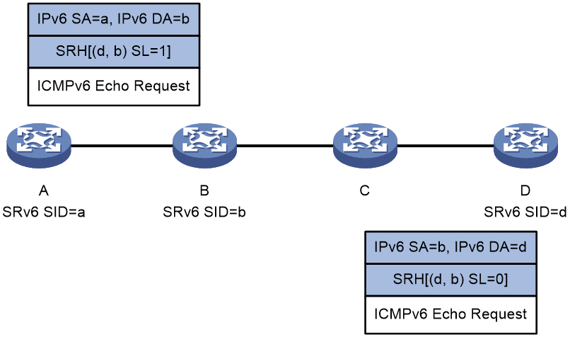
Figure 3 shows the segment-by-segment ping process as follows:
1. Device A initiates a ping to Device D, with the SRv6 SIDs of Device B and Device D specified. It constructs an ICMPv6 echo request encapsulated with an SRH and then forwards the request.
2. Upon receiving the ICMPv6 echo request, the intermediate node performs relevant operations depending on whether it is SRv6 capable:
¡ On an SRv6 capable node (such as Device B):
The node sends an ICMPv6 echo reply to Device A, and forwards the ICMPv6 echo request based on the SRH if the following conditions exist:
- The packet destination IPv6 address is the local SRv6 SID.
- The O-flag is set in the packet SRH Flags field.
¡ On an SRv6 incapable node (such as Device C):
The node forwards the ICMPv6 echo request according to routing table lookup without returning an ICMPv6 echo reply to Device A.
3. Upon receiving the ICMPv6 echo request with O-flag set and SL=0 in the SRH, Device D verifies the packet destination IPv6 address.
¡ If the IPv6 address is the local SRv6 SID, the verification succeeds, and Device D sends an ICMPv6 echo reply to Device A.
¡ If the IPv6 address is not the local SRv6 SID, the verification fails, and Device D discards the ICMPv6 echo request.
4. Device A determines whether the destination node is reachable based on reception of the ICMPv6 echo reply:
¡ If the ICMPv6 echo reply is received before the specified timeout timer expires, the destination node is reachable.
¡ If no ICMPv6 echo reply is received when the specified timeout timer expires, the destination node is unreachable.
End-to-end ping
An SRv6 SID-based end-to-end ping can be performed regardless of whether the End.OP SID is specified. This section describes such a ping operation without the End.OP SID specified.

Figure 4 shows the end-to-end ping process as follows:
1. Device A initiates a ping to Device D, with the SRv6 SIDs of Device B and Device D specified. It constructs an ICMPv6 echo request encapsulated with an SRH and then forwards the request.
2. Upon receiving the ICMPv6 echo request, the intermediate node performs relevant operations depending on whether it is SRv6 capable:
¡ On an SRv6 capable node (such as Device B):
The node forwards the ICMPv6 echo request based on the SRH if the packet destination IPv6 address is the local SRv6 SID.
¡ On an SRv6 incapable node (such as Device C):
The node forwards the ICMPv6 echo request according to routing table lookup.
3. Upon receiving the ICMPv6 echo request with SL=0 in the SRH, Device D verifies the packet destination IPv6 address.
¡ If the IPv6 address is the local SRv6 SID, the verification succeeds, and Device D sends an ICMPv6 echo reply to Device A.
¡ If the IPv6 address is not the local SRv6 SID, the verification fails, and Device D discards the ICMPv6 echo request.
4. Device A determines whether the destination node is reachable based on reception of the ICMPv6 echo reply:
¡ If the ICMPv6 echo reply is received before the specified timeout timer expires, the destination node is reachable.
¡ If no ICMPv6 echo reply is received when the specified timeout timer expires, the destination node is unreachable.
SRv6 SID-based tracert
SRv6 OAM supports overlay tracert and hop-by-hop tracert.
Overlay tracert
Use overlay tracert to display information about only SRv6 nodes in the SRv6 path.
In an overlay tracert operation, do not specify the End.OP SID because some nodes might fail to send a reply.
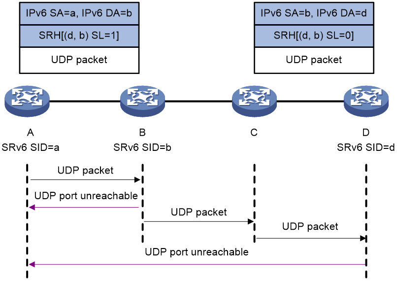
Figure 5 shows the overlay tracert process as follows:
1. Device A initiates a tracert to Device D, with the SRv6 SIDs of Device B and Device D specified. It constructs a UDP packet encapsulated with an SRH and then forwards the UDP packet (the Hop Limit value is 64 in the IPv6 packet header).
Make sure you specify a destination UDP port that is not used by any applications on the destination node.
2. Upon receiving the UDP packet, the intermediate node performs relevant operations depending on whether it is SRv6 capable:
¡ On an SRv6 capable node (such as Device B):
The node sends an ICMPv6 port unreachable message to Device A, and then forwards the UDP packet based on the SRH if the following conditions exist:
- The packet destination IPv6 address is the local SRv6 SID.
- The O-flag is set in the packet SRH Flags field.
¡ On an SRv6 incapable node (such as Device C):
The node forwards the UDP packet according to routing table lookup without returning an ICMPv6 port unreachable message.
3. Upon receiving the UDP packet with O-flag set and SL=0 in the SRH, Device D verifies the packet destination IPv6 address.
¡ If the IPv6 address is the local SRv6 SID, the verification succeeds, and Device D sends an ICMPv6 port unreachable message to Device A.
¡ If the IPv6 address is not the local SRv6 SID, the verification fails, and Device D discards the UDP packet.
4. Device A determines whether the destination node is reachable based on reception of the ICMPv6 port unreachable message:
¡ If the ICMPv6 port unreachable message is received before the specified timeout timer expires, the destination node is reachable. The tracert result displays the SRv6 path from the source node to the destination node.
¡ If no ICMPv6 port unreachable message is received when the specified timeout timer expires, the destination node is unreachable. You can locate the faulty node based on the tracert result.
Hop-by-hop tracert
Use hop-by-hop tracert to display information about all nodes (whether they are SRv6 capable or not) in the SRv6 path.
An SRv6 SID-based hop-by-hop tracert can be performed regardless of whether the End.OP SID is specified. This section describes such a tracert operation without the End.OP SID specified.
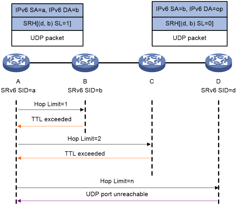
Figure 6 shows the hop-by-hop tracert process as follows:
1. Device A initiates a tracert to Device D, with the SRv6 SIDs of Device B and Device D specified. It constructs a UDP packet encapsulated with an SRH and then forwards the UDP packet (the Hop Limit value is 1 in the IPv6 packet header).
Make sure you specify a destination UDP port that is not used by any applications on the destination node.
2. Upon receiving the UDP packet with the Hop Limit value in the IPv6 packet header being 0, the intermediate node sends an ICMPv6 timeout message to Device A.
3. Upon receiving the ICMPv6 timeout message, Device A sends another UDP packet by adding the Hop limit value by 1.
4. Upon receiving the UDP packet with the Hop Limit value in the IPv6 packet header not being 0, the intermediate node forwards the UDP packet as follows:
¡ On an SRv6 capable node (such as Device B):
The node forwards the UDP packet based on the SRH if the packet destination IPv6 address is the local SRv6 SID.
¡ On an SRv6 incapable node (such as Device C):
The node forwards the UDP packet according to routing table lookup.
5. Upon receiving the UDP packet (with Hop Limit 0 in the IPv6 packet header and SL=0 in the SRH), Device D verifies the packet destination IPv6 address.
¡ If the IPv6 address is the local SRv6 SID, the verification succeeds, and Device D sends an ICMPv6 port unreachable message to Device A.
¡ If the IPv6 address is not the local SRv6 SID, the verification fails, and Device D discards the UDP packet.
6. Device A determines whether the destination node is reachable based on reception of the ICMPv6 port unreachable message:
¡ If the ICMPv6 port unreachable message is received before the specified timeout timer expires, the destination node is reachable. The tracert result displays the SRv6 path from the source node to the destination node.
¡ If no ICMPv6 port unreachable message is received when the specified timeout timer expires, the destination node is unreachable. You can locate the faulty node based on the tracert result.
SRv6 TE policy-based ping
Use SRv6 TE policy-based ping to detect reachability of each node in an SRv6 TE policy.
Figure 7 SRv6 TE policy-based ping

In Figure 7, the SID list of the SRv6 TE policy contains {b, d}. The SRv6 TE policy-based ping process is as follows:
1. Device A initiates a ping to Device D. It constructs an ICMPv6 echo request encapsulated with an SRH (that contains the SID list of the SRv6 TE policy) and then forwards the request.
2. Upon receiving the ICMPv6 echo request, the intermediate node performs relevant operations depending on whether it is SRv6 capable:
¡ On an SRv6 capable node (such as Device B):
The node sends an ICMPv6 echo reply to Device A, and forwards the ICMPv6 echo request based on the SRH to Device C if the following conditions exist:
- The packet destination IPv6 address is the local SRv6 SID.
- The O-flag is set in the packet SRH Flags field.
¡ On an SRv6 incapable node (such as Device C):
The node forwards the ICMPv6 echo request according to routing table lookup without returning an ICMPv6 echo reply to Device A.
3. Upon receiving the ICMPv6 echo request with O-flag set and SL=0 in the SRH, Device D verifies the packet destination IPv6 address.
¡ If the IPv6 address is the local SRv6 SID, the verification succeeds, and Device D sends an ICMPv6 echo reply to Device A.
¡ If the IPv6 address is not the local SRv6 SID, the verification fails, and Device D discards the ICMPv6 echo request.
4. Device A determines node reachability in the SRv6 TE policy based on reception of the ICMPv6 echo reply:
¡ If Device A receives the ICMPv6 echo reply from Device D before the specified timeout timer expires, all nodes in the SRv6 TE policy are reachable.
¡ If Device A does not receive the ICMPv6 echo reply from Device D when the specified timeout timer expires, the SRv6 TE policy contains unreachable nodes.
SRv6 TE policy-based tracert
Figure 8 SRv6 TE policy-based tracert

In 0, the SID list of the SRv6 TE policy contains {b, d}. The SRv6 TE policy-based tracert process is as follows:
1. Device A initiates a tracert to Device C. It constructs a UDP packet encapsulated with an SRH (that contains the SID list of the SRv6 TE policy) and then forwards the UDP packet (the Hop Limit value is 1 in the IPv6 packet header).
Make sure you specify a destination UDP port that is not used by any applications on the destination node.
2. Upon receiving the UDP packet with the Hop Limit value in the IPv6 packet header being 0, the intermediate node sends an ICMPv6 timeout message to Device A.
3. Upon receiving the ICMPv6 timeout message, Device A sends another UDP packet by adding the Hop Limit value by 1.
4. Upon receiving the UDP packet with the Hop Limit value in the IPv6 packet header not being 0, the intermediate node forwards the UDP packet as follows:
¡ On an SRv6 capable node (such as Device B):
The node forwards the UDP packet based on the SRH if the packet destination IPv6 address is the local SRv6 SID.
¡ On an SRv6 incapable node (such as Device C):
The node forwards the UDP packet according to routing table lookup.
5. Upon receiving the UDP packet (with Hop Limit 0 in the IPv6 packet header and SL=0 in the SRH), Device D verifies the packet destination IPv6 address.
¡ If the IPv6 address is the local SRv6 SID, the verification succeeds, and Device D sends an ICMPv6 port unreachable message to Device A.
¡ If the IPv6 address is not the local SRv6 SID, the verification fails, and Device D discards the UDP packet.
6. Device A determines node reachability in the SRv6 TE policy based on reception of the ICMPv6 port unreachable message:
¡ If Device A receives the ICMPv6 port unreachable message from the destination node before the specified timeout timer expires, all nodes in the SRv6 TE policy are reachable. No faulty nodes exist.
¡ If Device A does not receive the ICMPv6 port unreachable message from the destination node when the specified timeout timer expires, the SRv6 TE policy contains unreachable nodes. You can locate the faulty node based on the tracert result.
Ping-ce
In an EVPN VPWS over SRv6 or EVPN VPLS over SRv6 network, you can configure ping-ce on a PE to verify link connectivity between the PE and a CE. The PE broadcasts ARP requests or NS packets to all the ACs and PWs in the specified cross-connect or VSI. If the PE can receive an ARP/NA reply from the specified CE, it determines that the CE is reachable. If the PE cannot receive an ARP/NA reply from the specified CE within the default timeout time (2 seconds), it determines that the CE is unreachable.
Restrictions and guidelines: SRv6 OAM configuration
Follow these restrictions and guidelines when you perform an SRv6 SID-based ping or tracert operation:
· When End SID, End.X SID, End(COC32) SID, or End.X(COC32) SID is used as the SRv6 SID of the destination node, make sure the flavor type for the SRv6 SID is PSP.
· The End.DT4 SID, End.DT6 SID, or End.DT46 SID can be used only as the SRv6 SID of the destination node.
Performing an SRv6 SID-based ping operation
Restrictions and guidelines
For segment-by-segment ping, you cannot specify the End.OP SID.
Procedure
To perform an SRv6 SID-based ping operation, execute the following command in any view:
ping ipv6-sid [ -a source-ipv6 | -c count | -m interval | -q | -s packet-size | -t timeout | -tc traffic-class | -v ] * [ segment-by-segment ] { sid }&<1-10>
Performing an SRv6 SID-based tracert operation
Restrictions and guidelines
For overlay tracert, you cannot specify the End.OP SID.
Prerequisites
For hop-by-hop tracert, configure the following settings:
· Enable sending of ICMPv6 timeout packets on the intermediate devices (devices between the source and destination nodes).
· Enable sending of ICMPv6 timeout packets and ICMPv6 destination unreachable packets on the destination node.
For overlay tracert, enable sending of ICMPv6 destination unreachable packets on the intermediate devices (devices between the source and destination nodes) and destination node.
Procedure
To perform an SRv6 SID-based tracert operation, execute the following command in any view:
tracert ipv6-sid [ -a source-ipv6 | -f first-hop | -i interface-type interface-number | -m max-hops | -p port | -q packet-number | -t traffic-class | -w timeout ] * [ overlay ] { sid }&<1-10>
Performing an SRv6 TE policy-based ping operation
To perform an SRv6 TE policy-based ping operation, execute the following command in any view:
ping srv6-te policy { policy-name policy-name | color color-value end-point ipv6 ipv6-address | binding-sid bsid } [ end-op end-op ] [ -a source-ipv6 | -c count | -h hop-limit | -m interval | -s packet-size | -t timeout | -tc traffic-class ] *
Performing an SRv6 TE policy-based tracert operation
Prerequisites
Enable sending of ICMPv6 timeout packets on the intermediate devices (devices between the source and destination nodes) and destination node.
Enable sending of ICMPv6 destination unreachable packets on the destination node.
Procedure
To perform an SRv6 TE policy-based tracert operation, execute the following command in any view:
tracert srv6-te policy { policy-name policy-name | color color-value end-point ipv6 ipv6-address | binding-sid bsid } [ end-op end-op ] [ -a source-ipv6 | -f first-hop | -m max-hops | -p port | -q packet-number | -s packet-size | -tc traffic-class | -w timeout ] *
Specifying a remote End.OP SID locator
About this task
An End.OP SID is an SRv6 SID of OAM type used in SRv6 SID/SRv6 TE policy-based ping/tracert operations. When a device receives a request packet destined for the local End.OP SID, it further checks the SRv6 SID in the packet. If the SRv6 SID is the local SRv6 SID, the device sends a reply; if not, the device discards the packet.
To execute the ping srv6-te policy or tracert srv6-te policy command, you cannot ensure the SID connectivity in all SID lists when the following conditions exist:
· The last SIDs in the SID lists belong to different locators.
· An End.OP SID is specified with the end-op end-op option in the command.
To resolve this issue, you can configure the remote end-op command on the source node. The command enables you to specify a remote End.OP SID locator associated with the last SID of each SID list. In a ping or tracert operation, the source node will automatically select an End.OP SID by the longest match principle from the locator associated with the specified SID.
Procedure
1. Enter system view:
system-view
2. Enter SRv6 view:
segment-routing ipv6
3. Specify a remote End.OP SID locator.
remote end-op ipv6-address prefix-length
By default, no remote End.OP SID locators are specified.
Verifying link connectivity between a PE and a CE by using ping-ce
Restrictions and guidelines
When you execute the ping-ce or ping-ce ipv6 command, follow these restrictions and guidelines:
· The MAC address specified by the source-mac mac-address option must be within the sender MAC address range configured by using the l2vpn ping ce source-mac command.
· The IPv4/IPv6 address specified by the source-ip source-ip option must be an IPv4/IPv6 address not used by an interface of the local device.
· The IPv4/IPv6 address specified by the ip-address argument and that specified by the source-ip source-ip must be within the same network segment.
Before you execute the ping-ce or ping-ce ipv6 command, use the l2vpn ping ce source-mac command to configure the sender MAC address range.
Configuring the sender MAC address range
1. Enter system view.
system-view
2. Configure the sender MAC address range for the ping-ce operation.
l2vpn ping-ce source-mac start-mac-addres [ end-mac-addres ]
By default, no sender MAC address range is configured for the ping-ce operation.
Performing ping-ce to verify link connectivity between a PE and a CE
Verifying IPv4 link connectivity between a PE and a CE
To use ping-ce to verify IPv4 connectivity between a PE and a CE, execute the following command in any view:
ping-ce ip-address { vsi name | xconnect-group group-name connection connection-name } sender-ip source-ip [ source-mac source-mac ] [ -c count | -m wait-time | -s load-size ] *
Verifying IPv6 link connectivity between a PE and a CE
To use ping-ce to verify IPv6 connectivity between a PE and a CE, execute the following command in any view:
ping-ce ipv6 ipv6-address { vsi name | xconnect-group group-name connection connection-name } source-ip source-ip [ source-mac source-mac ] [ -c count | -m wait-time ] *
