- Table of Contents
-
- 07-Segment Routing Configuration Guide
- 00-Preface
- 01-SR-MPLS configuration
- 02-SRv6 configuration
- 03-SRv6 TE policy configuration
- 04-SRv6 VPN overview
- 05-IP L3VPN over SRv6 configuration
- 06-EVPN L3VPN over SRv6 configuration
- 07-EVPN VPWS over SRv6 configuration
- 08-Public network IP over SRv6 configuration
- 09-SRv6 OAM configuration
- Related Documents
-
| Title | Size | Download |
|---|---|---|
| 02-SRv6 configuration | 333.99 KB |
Microloop avoidance after a network failure
SR microloop avoidance after a failure recovery
Configuring dynamic End.X SID deletion delay
Using IGP to advertise SRv6 SIDs
Disabling an interface from participating in TI-LFA calculation
Enabling FRR microloop avoidance
Enabling SR microloop avoidance
Configuring SR microloop avoidance to encapsulate only strict SIDs in the SID list
Enabling SNMP notifications for SRv6
Display and maintenance commands for SRv6
Example: Configuring IPv6 IS-IS TI-LFA FRR
Configuring SRv6
About SRv6
Segment Routing (SR) is a source routing technology. The source node selects a path for packet forwarding, and then encodes the path in the packet header as an ordered list of segments. Each segment is identified by the Segment Identifier (SID). The SR nodes along the path forward the packets based on the SIDs in the packets. Only the source node needs to maintain the path status.
IPv6 Segment Routing (SRv6) uses IPv6 addresses as SIDs to forward packets.
Basic concepts
SR node
An SR node is a node that supports the SRv6 feature. The following SR nodes are available:
· Ingress node (source node)—Selects a path for packet forwarding, encodes the path as an ordered SID list in the routing extension header.
· Transit node—Forwards the packets based on the SID list.
· Egress node (tail node)—Removes the routing extension header and forwards the packets to the destination.
SID
SRv6 supports SRv6 SIDs that have specific functions.
An SRv6 SID is in the format of IPv6 address, but the IPv6 address does not belong to any interface on any device.
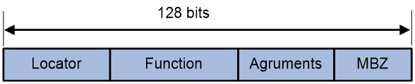
As shown in Figure 1, an SRv6 SID contains the Locator, Function, Arguments, and Must be zero (MBZ) portions.
· Locator—Identifies the network segment of the SID. The locator of an SRv6 SID must be unique in the SR domain.
· Function—Contains an opcode that identifies the network function of an SID. An SR node will execute the function in the SRv6 SID Function field of an SRv6 packet after it receives that SRv6 packet.
· Arguments—Defines flow and service parameters for SRv6 packets.
· MBZ—When the total number of bits in the Locator, Function, and Arguments portions is less than 128 bits, the remaining bits are padded with 0s.
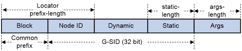
According to whether SRv6 SIDs are compressible, SRv6 SIDs are divided into the following categories for a locator:
· Non-compressible SRv6 SIDs—Include static and dynamic SRv6 SIDs. The formats are as follows:
¡ Static SRv6 SID = ipv6-prefix + 0s + opcode + 0s.
- The ipv6-prefix portion is specified by using the ipv6-address and prefix-length arguments in the locator command. The number of bits occupied by the ipv6-prefix portion is determined by the prefix-length argument.
- The number of bits occupied by 0s (following the ipv6-prefix portion) is determined by the dynamic-length argument.
- The opcode portion is specified by using the opcode command. The number of bits occupied by the opcode portion is determined by the static-length argument.
- The number of bits occupied by 0s (following the opcode portion) is determined by the args-length argument.
¡ Dynamic SRv6 SID = ipv6-prefix + dynamic + 0s.
- The ipv6-prefix portion is specified by using the ipv6-address and prefix-length arguments in the locator command. The number of bits occupied by the ipv6-prefix portion is determined by the prefix-length argument.
- The dynamic portion is dynamically assigned by IGP or BGP. The number of bits occupied by the dynamic portion is determined by the dynamic-length argument.
- The number of bits occupied by 0s is the sum of the values for the static-length and args-length arguments.
For example, use the locator test1 ipv6-prefix 100:200:DB8:ABCD:: 64 static 24 args 32 command.
¡ The locator is 100:200:DB8:ABCD::. The length is 64 bits.
¡ The static portion length is 24 bits.
¡ The Args portion length is 32 bits.
¡ The dynamic portion length is 8 bits.
In this example, the following non-compressible static SRv6 SID range and dynamic SRv6 SID range are obtained on the locator:
¡ The start value for static SRv6 SIDs is 100:200:DB8:ABCD:0:1::.
¡ The end value for static SRv6 SIDs is 100:200:DB8:ABCD:FF:FFFF::.
¡ The start value for dynamic SRv6 SIDs is 100:200:DB8:ABCD:100::.
¡ The end value for dynamic SRv6 SIDs is 100:200:DB8:ABCD:FFFF:FFFF::.
Figure 2 Non-compressible SRv6 SIDs

· Compressible SRv6 SID—(This type of SRv6 SID is not supported in the current software version.) You can specify compressible SRv6 SIDs in a static segment or use IGP to automatically allocate compressible SRv6 SIDs in a dynamic segment. For example, use the locator test1 ipv6-prefix 100:200:DB8:ABCD:: 64 common-prefix 48 coc32 static 8 args 16 command.
¡ The locator is 100:200:DB8:ABCD::. The length is 64 bits.
¡ The common prefix length is 48 bits. A compressed SRv6 SID does not contain this portion.
¡ The static portion length is 8 bits.
¡ The Args portion length is 16 bits.
¡ The dynamic portion length is 8 bits.
In this example, the following compressible static SRv6 SID range and dynamic SRv6 SID range are obtained on the locator:
¡ The start value for static SRv6 SIDs is 100:200:DB8:ABCD:1::.
¡ The end value for static SRv6 SIDs is 100:200:DB8:ABCD:FF::.
¡ The start value for dynamic SRv6 SIDs is100:200:DB8:ABCD:100::.
¡ The end value for dynamic SRv6 SIDs is 100:200:DB8:ABCD:FFFF::.
Figure 3 Compressible SRv6 SIDs
According to the functions of SRv6 SIDs, SRv6 SIDs are divided into the following categories:
· End SID—Identifies the prefix of a destination address in the network.
· End.X SID—Identifies a link in the network.
· End.DT4 SID—Identifies an IPv4 VPN in the network. The function of an End.DT4 SID is decapsulating packets and searching the routing table of the corresponding IPv4 VPN instance to forward the packets. End.DT4 SIDs are applicable to IPv4 private network access scenarios.
· End.DT6 SID—Identifies an IPv6 VPN in the network. The function of an End.DT6 SID is decapsulating packets and searching the routing table of the corresponding IPv6 VPN instance to forward the packets. End.DT6 SIDs are applicable to IPv6 private network access scenarios.
· End.DT46 SID—Identifies an IPv4 or IPv6 VPN in the network. End.DT46 SIDs are applicable to IPv4 and IPv6 private network concurrent access scenarios.
· End.DX2 SID—Identifies one end of a Layer 2 cross-connect. The function of an End.DX2 SID is removing the outer IPv6 header and SRH of packets and forwarding the decapsulated packets to the output interface of the SID. End.DX2 SIDs are applicable to EVPN VPWS scenarios.
· End.DX2L SID—Identifies packets that come from a bypass SRv6 PW. The packets will not be forwarded back to the bypass SRv6 PW for loop prevention. The function of an End.DX2L SID is removing the outer IPv6 header and SRH of packets and forwarding the decapsulated packets to the output interface of the SID. End.DX2L SIDs are applicable to EVPN VPWS over SRv6 multihomed sites.
· End.OP SID—Applies to the SRv6 OAM scenario. For more information about End.OP SIDs, see "Configuring SRv6 OAM."
Use IGP to advertise SRv6 SIDs for an SR node. The other SR nodes will generate route entries of that SR node based on the advertised information.
SRv6 SID flavors
Use SRv6 SID flavors to change the forwarding behaviors of SRv6 SIDs in order to meet multiple service requirements. The following SRv6 SID flavors are supported:
· Penultimate Segment POP of the SRH (PSP)—The penultimate SRv6 node removes the SRH to reduce the workload of the end SRv6 node and improve the forwarding efficiency. The end SRv6 node does not read the SRH, and it only looks up the local SID table for the destination IPv6 address of packets to forward the packets.
· NO PSP—The penultimate SRv6 node does not remove the SRH.
Local SID forwarding table
An SRv6-enabled node maintains a local SID forwarding table that records the SRv6 SIDs generated on the local node. The local SID forwarding table has the following functions:
· Stores local generated SRv6 SID forwarding information.
· Stores SRv6 SID operation types.
Segment List
A Segment List is an ordered list of SIDs, which is also referred to as a Segment Identifier (SID) list in this document. The SR nodes forward packets based on the SIDs in the order that they are arranged in the SID list.
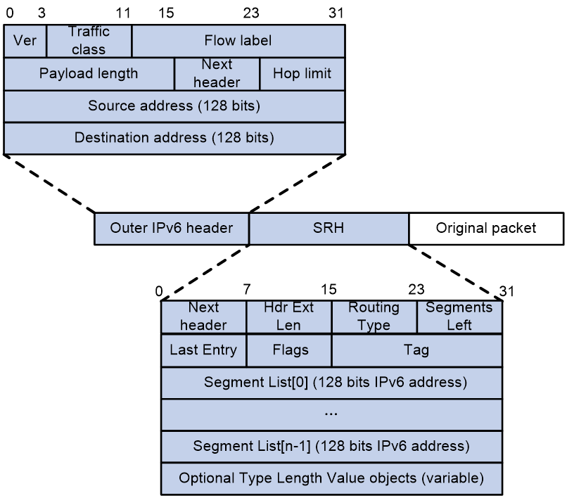
SRv6 packet format
An outer IPv6 header and a Segment Routing Header (SRH) are added to the original Layer 3 data packet to form an SRv6 packet.
As shown in Figure 4, the value for the Next Header field is 43 in the outer IPv6 header, which indicates that the header next to the IPv6 header is a routing extension header. The value for the Routing Type field in the routing extension header is 4, which indicates that the routing extension header is an SRH. The SRH header contains the following fields:
· 8-bit Next Header—Identifies the type of the header next to the SRH.
· 8-bit Hdr Ext Len—Length of the SRH header in 8-octet units, not including the first 8 octets.
· 8-bit Routing Type—The value for this field is 4, which represents SRH.
· 8-bit Segments Left—Contains the index of the next segment to inspect in the Segment List. The Segments Left field is set to n-1 where n is the number of segments in the Segment List. Segments Left is decremented at each segment.
· 8-bit Last Entry—Contains the index of the first SID in the path used to forward the packet.
· 8-bit Flags—Contains flags.
· 16-bit Tag—Tags a packet as part of a class or group of packets, for example, packets sharing the same set of properties.
· Segment List—Contains 128-bit IPv6 addresses representing the ordered segments. The Segment List is encoded starting from the last segment of the path. The first element of the segment list (Segment List [0]) contains the last segment of the path, the second element (Segment List [1]) contains the penultimate segment of the path and so on. The number enclosed in a pair of brackets is the index of a segment.
TI-LFA FRR
Topology-Independent Loop-Free Alternate Fast Re-Route (TI-LFA FRR) provides link and node protection for SRv6 tunnels. When a link or node fails, TI-LFA FRR switches the traffic to the backup path to ensure continuous data forwarding.
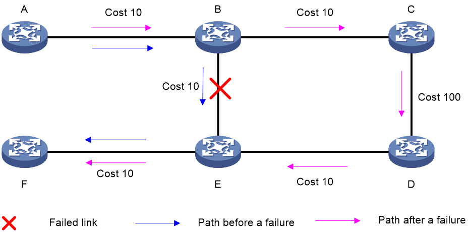
TI-LFA FRR background
As shown in Figure 5, node A sends data packets to node F. When the link between node B and node E fails, node B forwards the data packets to node C. The cost of the link between node C and node D is 100 (which is greater than the cost of the link between node C and node D) and the routes on node C have not converged. As a result, node C determines that the next hop of the optimal path to reach node F is node B. Then, node C forwards the data packets back to node B, which causes a loop.
Figure 5 TI-LFA application scenario

To resolve this issue, deploy TI-FLA on the SRv6 network. As shown in Figure 6, when the link between node B and node E fails, node B uses the backup path calculated by TI-LFA to forward the data packets along the B->C->D->E path.
Figure 6 TI-LFA forwarding network diagram
TI-LFA FRR concepts
· P space—Use the source node of the protected link as the root to establish a shortest path tree. All nodes that are reachable from the source node without passing the protected link form the P space. Nodes in the P space are called P nodes.
· Extended P space—Use the source node of the protected link and its neighbors as the roots to establish shortest path trees. All nodes that are reachable from the source node or one of its neighbors without passing the protected link form the extended P space. The P space is a subset of the extended P space.
· Q space—Use the destination node of the protected link as the root to establish a reverse shortest path tree. All nodes that are reachable from the root node without passing the protected link form the Q space. Nodes in the Q space are called Q nodes.
· Repair list—A constraint path used to indicate how a P node reaches a Q node when the P space and Q space do not have common nodes. The repair list contains the following SRv6 SIDs:
¡ SRv6 SIDs of P nodes.
¡ SRv6 SIDs from P nodes to nearest Q nodes.
TI-LFA FRR path calculation
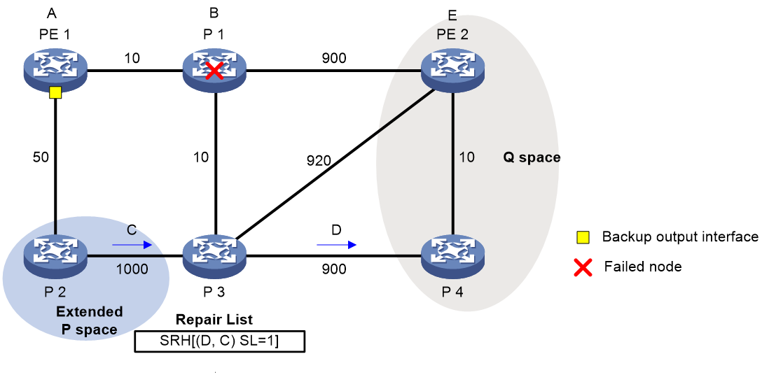
As shown in Figure 7, PE 1 is the source node. P 1 is the faulty node. PE 2 is the destination node. The numbers on links represent the link costs. A data flow traverses PE 1, P 1, and PE 2. To protect data against P 1 failure, TI-LFA FRR calculates the extended P space, Q space, shortest path tree converged after P 1 fails, repair list, and backup output interface, and creates the backup forwarding entry.
TI-LFA FRR calculates the backup path by using the following steps:
1. Calculates the extended P space: P 2.
2. Calculates the Q space: PE 2 and P 4.
3. Calculates the shortest path tree converged after P 1 fails: PE 1 --> P 2 --> P 4 --> PE 2.
4. Calculates the repair list: End.X SID C of the link between P 2 and P 3 and End.X SID D of the link between P 3 and P 4.
5. Calculates the backup output interface, that is, the output interface to the next hop after the link from PE 1 to P 1 fails.
TI-LFA FRR forwarding process
After TI-LFA FRR finishes backup path calculation, traffic will be switched to the backup path in response to a primary path failure.
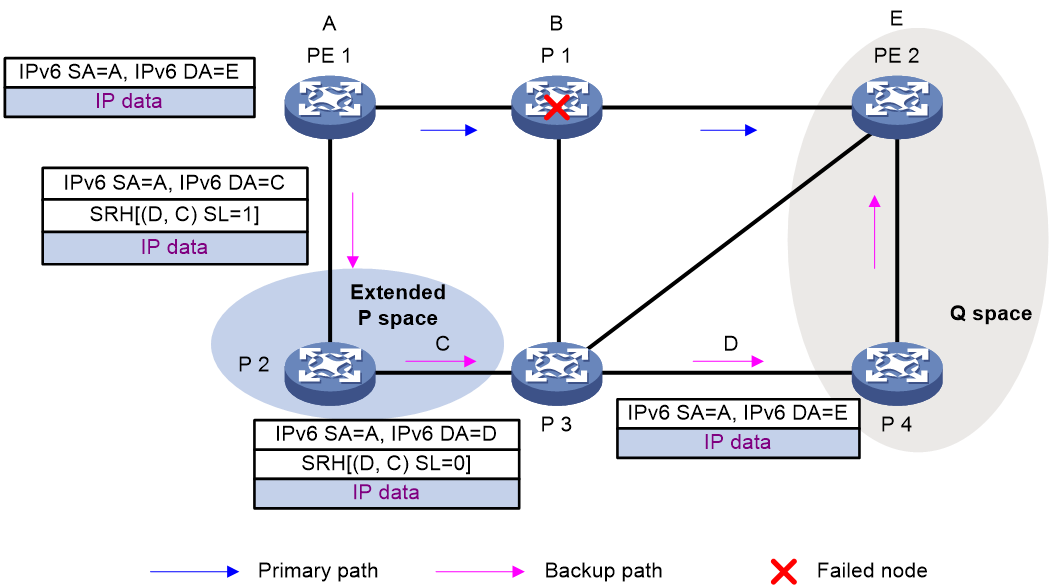
As shown in Figure 8, P 2 is a P node and P 4 and PE 2 are Q nodes. When the next hop on the primary path (P 1) fails, TI-LFA FRR switches the traffic to the backup path. The following are the detailed steps:
1. PE 1 looks up the IPv6 routing table for the destination IPv6 address of a packet and finds that the next hop is P 2. PE 1 encapsulates the packet according to the repair list.
¡ Adds an SRH header. The SID list is Segment List [0]=D and Segment List [1]=C. The SIDs are arranged from the farthest node to the nearest node.
¡ Adds an outer IPv6 header. The source address is address A on source node PE 1 and the destination address is the address pointed by SL. Because the SL is 1, the destination address is C as pointed by Segment List [1].
2. After P2 receives the packet, it performs the following operations:
a. Checks the SL value in the SRH header and decreases the value by 1.
b. Searches for the address pointed by Segment List [0] and finds that the address is End.X SID D between P 3 and P 4.
c. Replaces the destination address in the outer IPv6 header with End.X SID D.
d. Obtains the output interface and next hop according to End.X SID C and forwards the encapsulated packet to P 3.
3. After P3 receives the packet, it performs the following operations:
a. Checks the SL value in the SRH header and finds that the SL value is 0.
b. Decapsulates the packet.
c. Obtains the output interface and next hop according to End.X SID D and forwards the packet to P 4.
4. After P4 receives the packet, it searches the IP routing table for the destination IP address of the packet and forwards the packet to PE 2.
Figure 8 Data forwarding over the TI-LFA FRR backup path
Microloop avoidance after a network failure
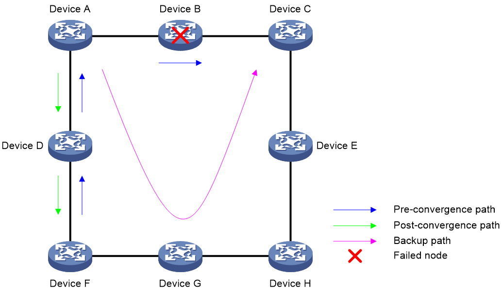
As shown in Figure 9, when Device B fails, traffic to Device C will be switched to the backup path calculated by TI-LFA. After Device A finishes route convergence, traffic will be switched to the post-convergence path. If Device D and Device F have not finished route convergence and still forward traffic along the pre-convergence path, a loop is formed between Device A and Device F. The loop exists until Device D and Device F finish route convergence.
FRR microloop avoidance and SR microloop avoidance can resolve this issue. After you configure TI-LFA, Device A first switches traffic to the backup path calculated by TI-LFA when Device B fails. Then, Device A waits for Device D and Device F to finish route convergence before starting route convergence. After Device A also finishes route convergence, Device A switches the traffic to the converged route.
Figure 9 Diagram for microloop avoidance after a network failure
SR microloop avoidance after a failure recovery
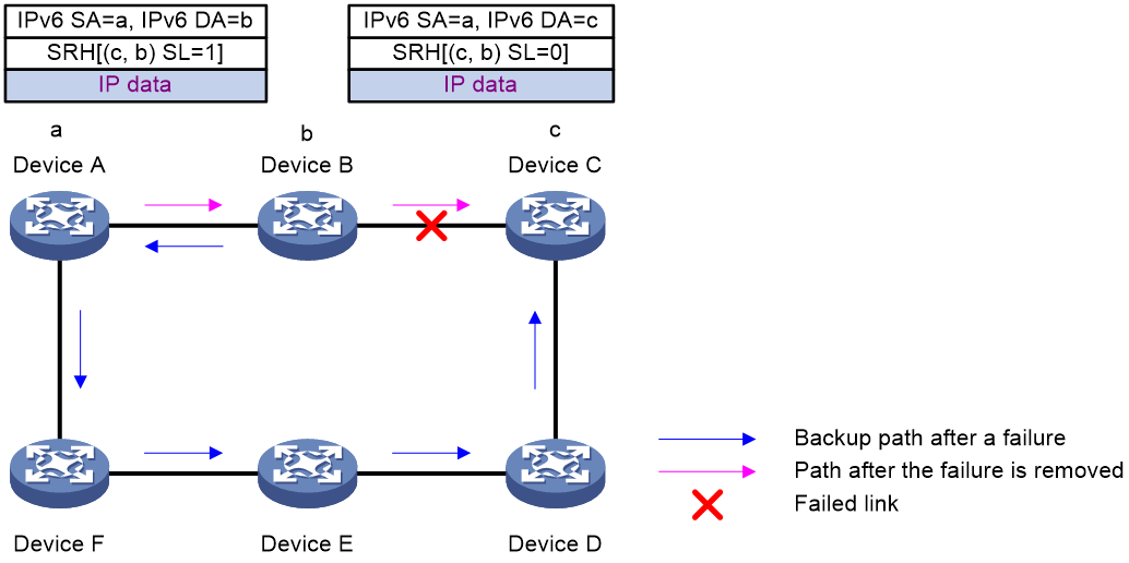
As shown in Figure 10, before the link between Device B and Device C recovers, traffic traverses along the backup path. After the link recovers, Device A forwards the traffic to Device B if Device A finishes route convergence before Device B. With route convergence unfinished, Device B still forwards the traffic along the backup path. A loop is formed between Device A and Device B.
SR microloop avoidance can resolve this issue. After the link recovers, SR microloop avoidance automatically calculates the optimal path from Device A to Device C and forwards traffic along the path. To forward a packet along the newly calculated path, Device A adds, for example, the adjacency SID from Device B to Device C, to the packet and then sends the packet to Device B. Then, Device B forwards the packet to Device C based on the path information.
Upon expiration of the microloop avoidance RIB-update-delay timer and completion of route convergence on Device B, Device A does not add path information to packets anymore. It will forward packets to Device C as usual.
Figure 10 Diagram for SR microloop avoidance after a failure recovery
Protocols and standards
· draft-previdi-6man-segment-routing-header
· draft-ietf-6man-segment-routing-header
· draft-filsfils-spring-segment-routing
· draft-filsfils-spring-srv6-network-programming
SRv6 tasks at a glance
To configure SRv6, perform the following tasks:
2. (Optional.) Manage SRv6 SIDs
¡ Configuring dynamic End.X SID deletion delay
3. Using IGP to advertise SRv6 SIDs
4. (Optional.) Configuring TI-LFA FRR
5. (Optional.) Enabling SNMP notifications for SRv6
Configuring an SRv6 SID
Restrictions and guidelines
Each locator must have a unique name.
Do not configure the same IPv6 address prefix and prefix length for different locators. In addition, the IPv6 address prefixes of different locators cannot overlap.
You cannot disable SRv6 or delete a locator in SRv6 view if the locator has dynamic SRv6 SIDs that are being used.
When you configure an SRv6 SID, follow these restrictions and guidelines:
· The total length of the IPv6 address prefix and prefix length portion and the dynamic segment portion must be greater than 96. That is, the total length of the argument and static segment portions must be equal to or smaller than 31.
· The length of the argument portion must be equal to or smaller than 16.
Procedure
1. Enter system view.
system-view
2. Enable SRv6 and enter SRv6 view.
segment-routing ipv6
3. Configure a locator and enter SRv6 locator view.
locator locator-name [ ipv6-prefix ipv6-address prefix-length [ args args-length | static static-length ] * ]
4. (Optional.) Enable anycast for the locator.
anycast enable
By default, anycast is disabled for a locator.
A locator is an anycast locator if the A-bit is set in the Flags field of the Locator TLV in routing protocol packets. An anycast locator is shared by a group of SRv6 nodes.
5. Configure an opcode. Perform one of the following tasks:
¡ Configure an End SID.
opcode { opcode | hex hex-opcode } end
¡ Configure an End.X SID.
opcode { opcode | hex hex-opcode } end-x interface interface-type interface-number nexthop nexthop-ipv6-address
¡ Configure an End.DT4 SID.
opcode { opcode | hex hex-opcode } end-dt4 [ vpn-instance vpn-instance-name [ evpn | l3vpn-evpn ] ]
The specified VPN instance must exist. An End.DT4 SID cannot be configured in different VPN instances.
¡ Configure an End.DT6 SID.
opcode { opcode | hex hex-opcode } end-dt6 [ vpn-instance vpn-instance-name [ evpn | l3vpn-evpn ] ]
The specified VPN instance must exist. An End.DT6 SID cannot be configured in different VPN instances.
¡ Configure an End.DT46 SID.
opcode { opcode | hex hex-opcode } end-dt46 [ vpn-instance vpn-instance-name [ evpn | l3vpn-evpn ] ]
The specified VPN instance must exist. An End.DT46 SID cannot be configured in different VPN instances.
¡ Configure an End.DX2 SID.
opcode { opcode | hex hex-opcode } end-dx2 xconnect-group group-name connection connection-name
The specified cross-connect group and cross-connect must exist.
¡ Configure an End.DX2L SID.
opcode { opcode | hex hex-opcode } end-dx2l xconnect-group group-name connection connection-name
The specified cross-connect group and cross-connect must exist.
¡ Configure an End.OP SID.
opcode { opcode | hex hex-opcode } end-op
Configuring dynamic End.X SID deletion delay
About this task
Packet loss occurs between OSPFv3 or IS-IS neighbors if the neighbors frequently delete and request dynamically allocated End.X SIDs for the links between them because of neighbor flapping. To resolve this issue, set a delay timer for deleting dynamically allocated End.X SIDs when the neighbors are disconnected. If the neighbors are still disconnected when the delay timer expires, the device deletes the dynamically allocated End.X SIDs.
Restrictions and guidelines
The device always immediately deletes automatically allocated End.X SIDs without any delay in the following situations:
· The reset ospfv3 process command is executed. For more information about this command, see OSPFv3 commands in Layer 3—IP Routing Command Reference.
· The reset isis all command is executed. For more information about this command, see IS-IS commands in Layer 3—IP Routing Command Reference.
· Interfaces are deleted or removed. For example, an interface module is removed or a subinterface is deleted.
Procedure
1. Enter system view.
system-view
2. Enter IS-IS IPv6 address family view or OSPFv3 process view.
¡ Execute the following commands in sequence to enter IS-IS IPv6 address family view:
isis [ process-id ] [ vpn-instance vpn-instance-name ]
address-family ipv6 [ unicast ]
¡ Enter OSPFv3 process view.
ospfv3 [ process-id | vpn-instance vpn-instance-name ] *
3. Enable dynamic End.X SID deletion delay and set the delay time.
segment-routing ipv6 end-x delete-delay [ time-value ]
By default, dynamic End.X SID deletion delay is enabled and the delay time is 1800 seconds.
If the delay time is 0 seconds, dynamic End.X SID deletion delay is disabled.
Using IGP to advertise SRv6 SIDs
About this task
Use an IGP protocol to advertise the SRv6 SID of a locator by applying the locator to the IGP protocol.
Prerequisites
If IS-IS is used to advertise SRv6 SIDs, make sure the cost style of IS-IS is wide, compatible, or wide-compatible. For more information about the cost styles of IS-IS, see Layer 3—IP Routing Configuration Guide.
Using IS-IS to advertise SRv6 SIDs
1. Enter system view.
system-view
2. Enter IS-IS process view.
isis [ process-id ] [ vpn-instance vpn-instance-name ]
3. Enter IS-IS IPv6 address family view.
address-family ipv6 [ unicast ]
4. Apply a locator to IS-IS IPv6 address family.
segment-routing ipv6 locator locator-name [ level-1 | level-2 ] [ auto-sid-disable ]
By default, no locators are applied to IS-IS IPv6 address family.
Repeat this command to apply multiple locators to IS-IS IPv6 address family for the family to advertise multiple SRv6 SIDs.
Using OSPFv3 to advertise SRv6 SIDs
1. Enter system view.
system-view
2. Enter OSPFv3 process view.
ospfv3 [ process-id | vpn-instance vpn-instance-name ] *
3. Apply a locator to the OSPFv3 process.
segment-routing ipv6 locator locator-name [ auto-sid-disable ]
By default, no locators are applied to an OSPFv3 process.
Repeat this command to apply multiple locators to the OSPFv3 process for the process to advertise multiple SRv6 SIDs.
Configuring TI-LFA FRR
TI-LFA FRR tasks at a glance
To configure TI-LFA FRR, perform the following tasks:
2. (Optional.) Disabling an interface from participating in TI-LFA calculation
On the source node, disable TI-LFA on the route's output interface to the next hop on the primary path.
3. (Optional.) Enabling FRR microloop avoidance
4. (Optional.) Configuring SR microloop avoidance
¡ Enabling SR microloop avoidance
¡ Configuring SR microloop avoidance to encapsulate only strict SIDs in the SID list
Enabling TI-LFA FRR
Enabling IPv6 IS-IS TI-LFA FRR
1. Enter system view.
system-view
2. Enter IS-IS view.
isis process-id
3. Enter IS-IS IPv6 unicast address family view.
address-family ipv6
4. Enable LFA FRR for IPv6 IS-IS.
fast-reroute lfa [ level-1 | level-2 ]
By default, LFA FRR is disabled for IPv6 IS-IS.
5. Enable TI-LFA FRR for IPv6 IS-IS.
fast-reroute ti-lfa [ per-prefix ] [ route-policy route-policy-name | host ] [ level-1 | level-2 ]
By default, TI-LFA FRR is disabled for IPv6 IS-IS.
6. (Optional.) Set the priority for an FRR backup path selection policy.
fast-reroute tiebreaker { lowest-cost | node-protecting | srlg-disjoint } preference preference [ level-1 | level-2 ]
By default, the priority values of the lowest-cost, node-protection, and SRLG-disjoint backup path selection policies are 20, 40, and 10, respectively.
Enabling OSPFv3 TI-LFA FRR
1. Enter system view.
system-view
2. Enter OSPFv3 view.
ospfv3 [ process-id | vpn-instance vpn-instance-name ] *
3. Enable LFA FRR for OSPFv3.
fast-reroute { lfa [ abr-only ] | route-policy route-policy-name }
By default, LFA FRR is disabled for OSPFv3.
4. Enable TI-LFA FRR for OSPFv3.
fast-reroute ti-lfa [ per-prefix ] [ route-policy route-policy-name | host ]
By default, TI-LFA FRR is disabled for OSPFv3.
5. (Optional.) Set the priority for FRR backup path selection policies.
fast-reroute tiebreaker { lowest-cost | node-protecting } preference preference
By default, the priority values of the lowest-cost and node-protection backup path selection policies are 20 and 40, respectively.
Disabling an interface from participating in TI-LFA calculation
Disabling an IPv6 IS-IS interface from participating in TI-LFA calculation
1. Enter system view.
system-view
2. Enter the view of IPv6 IS-IS interface.
interface interface-type interface-number
3. Disable the interface from participating in TI-LFA calculation.
isis ipv6 fast-reroute ti-lfa disable [ level-1 | level-2 ]
By default, an IPv6 IS-IS interface participates in TI-LFA calculation.
Disabling an OSPFv3 interface from participating in TI-LFA calculation
1. Enter system view.
system-view
2. Enter the view of OSPFv3 interface.
interface interface-type interface-number
3. Disable the interface from participating in TI-LFA calculation.
ospfv3 fast-reroute ti-lfa disable [ instance instance-id ]
By default, an OSPFv3 interface participates in TI-LFA calculation.
Enabling FRR microloop avoidance
About this task
FRR microloop avoidance provides microloop avoidance after a network failure.
On a network deployed with TI-LFA FRR, when a node or link fails, traffic will be switched to the backup path calculated by TI-LFA. If devices on the backup path have not finished route convergence, a loop is formed between the source node (failed node or the previous node along the link) and a device on the backup path. The loop exists until the devices on the backup path finish route convergence.
To resolve this issue, FRR microloop avoidance first switches traffic to the backup path calculated by TI-LFA after the node or link failure. Then, the source node waits for the nodes on the backup path to finish route convergence before starting route convergence.
Restrictions and guidelines
If you configure both FRR microloop avoidance and SR microloop avoidance, SR microloop avoidance takes effect.
Configuring IPv6 IS-IS FRR microloop avoidance
1. Enter system view.
system-view
2. Enter IS-IS view.
isis process-id
3. Enter IS-IS IPv6 unicast address family view.
address-family ipv6
4. Enable FRR microloop avoidance for IS-IS.
fast-reroute microloop-avoidance enable [ level-1 | level-2 ]
By default, FRR microloop avoidance is disabled for IS-IS.
5. (Optional.) Set the FRR microloop avoidance RIB-update-delay time.
fast-reroute microloop-avoidance rib-update-delay delay-time [ level-1 | level-2 ]
By default, the FRR microloop avoidance RIB-update-delay time is 5000 ms.
Enabling SR microloop avoidance
About this task
SR microloop avoidance provides microloop avoidance after both a network failure and a failure recovery.
After a network failure occurs or recovers, route convergence occurs on relevant network devices. Because of nonsimultaneous convergence on network devices, microloops might be formed. After you configure SR microloop avoidance, the devices will forward traffic along the specified path before route convergence is finished on all the relevant network devices. Because the forwarding path is independent of route convergence, microloops are avoided.
To ensure sufficient time for IGP to complete route convergence, set the SR microloop avoidance RIB-update-delay time. Before the timer expires, faulty relevant devices will forward traffic along the specified path. Upon expiration of the timer and completion of IGP route convergence, traffic will traverse along the IGP-calculated path.
Restrictions and guidelines
If you configure both FRR microloop avoidance and SR microloop avoidance, SR microloop avoidance takes effect.
Configuring IPv6 IS-IS SR microloop avoidance
1. Enter system view.
system-view
2. Enter IS-IS view.
isis process-id
3. Enter IS-IS IPv6 unicast address family view.
address-family ipv6
4. Enable SR microloop avoidance for IPv6 IS-IS.
segment-routing microloop-avoidance enable [ level-1 | level-2 ]
By default, SR microloop avoidance is disabled for IPv6 IS-IS.
5. (Optional.) Set the SR microloop avoidance RIB-update-delay time.
segment-routing microloop-avoidance rib-update-delay delay-time [ level-1 | level-2 ]
By default, the SR microloop avoidance RIB-update-delay time is 5000 ms.
Configuring OSPFv3 SR microloop avoidance
1. Enter system view.
system-view
2. Enter OSPFv3 process view.
ospfv3 [ process-id | vpn-instance vpn-instance-name ] *
3. Enable SR microloop avoidance for OSPFv3.
segment-routing microloop-avoidance enable
By default, SR microloop avoidance is disabled for OSPFv3.
4. (Optional.) Set the SR microloop avoidance RIB-update-delay time.
segment-routing microloop-avoidance rib-update-delay delay-time
By default, the SR microloop avoidance RIB-update-delay time is 5000 ms.
Configuring SR microloop avoidance to encapsulate only strict SIDs in the SID list
About this task
By default, SR microloop avoidance first calculates the End SID to the P node, and then calculates the End.X SIDs from the P node to the destination node. Then, the SIDs are encapsulated into the SRH in the order of the End SID of the P node and the End.X SIDs from the P node to the destination node.
If multipoint failure exists and the forwarding path is frequently switched, a microloop might exist on the path to the P node identified by the End SID. To resolve this issue, use this feature to strictly constrain the path to the P node.
This feature strictly constrains the path to the P node by calculating an End.X SID to reach the P node. The SIDs are encapsulated into the SID list of the SRH in the order of the End.X SID to the P node and the End.X SIDs from the P node to the destination node.
Procedure
1. Enter system view.
system-view
2. Enter IS-IS view.
isis process-id
3. Enter IS-IS IPv6 unicast address family view.
address-family ipv6
4. Configure SR microloop avoidance to encapsulate only strict SIDs in the SID list.
segment-routing microloop-avoidance strict-sid-only
By default, the strict-SID-only feature is not configured for SR microloop avoidance.
Enabling SNMP notifications for SRv6
About this task
Use this feature to report critical SRv6 events to an NMS. For SRv6 event notifications to be sent correctly, you must also configure SNMP on the device. For more information about SNMP configuration, see Network Management and Monitoring Configuration Guide.
Procedure
1. Enter system view.
system-view
2. Enable SNMP notifications for SRv6.
snmp-agent trap enable srv6
By default, SNMP notifications are disabled for SRv6.
Display and maintenance commands for SRv6
Execute display commands in any view.
|
Task |
Command |
|
Display IS-IS SRv6 capability information. |
display isis segment-routing ipv6 capability [ level-1 | level-2 ] [ process-id ] |
|
Display IS-IS SRv6 locator routing information. |
display isis segment-routing ipv6 locator [ ipv6-address prefix-length ] [ [ level-1 | level-2 ] | verbose ] * [ process-id ] |
|
Display OSPFv3 SRv6 capability information. |
display ospfv3 [ process-id ] segment-routing ipv6 capability |
|
Display brief SRv6 information. |
display segment-routing ipv6 brief |
|
Display SRv6 forwarding entries. |
display segment-routing ipv6 forwarding [ entry-id ] [ slot slot-number ] |
|
Display information about the SRv6 local SID forwarding table. |
display segment-routing ipv6 local-sid { end | end-b6encaps | end-b6encapsred | end-b6insert | end-b6insertred | end-dx2 | end-dx2l | end-op } [ sid ] display segment-routing ipv6 local-sid { end-dt4 | end-dt46 | end-dt6 } [ sid | vpn-instance vpn-instance-name ] display segment-routing ipv6 local-sid end-x [ sid | interface interface-type interface-number [ nexthop nexthop-ipv6-address ] ] |
|
Display SRv6 locator information. |
display segment-routing ipv6 locator [ locator-name ] |
SRv6 configuration examples
Example: Configuring IPv6 IS-IS TI-LFA FRR
Network configuration
As shown in Figure 11, complete the following tasks to implement TI-LFA FRR:
· Configure IPv6 IS-IS on Device A, Device B, Device C, and Device D to achieve network level connectivity.
· Configure IS-IS SRv6 on Device A, Device B, Device C, and Device D.
· Configure TI-LFA FRR to remove the loop on Link B and to implement fast traffic switchover to Link B when Link A fails.
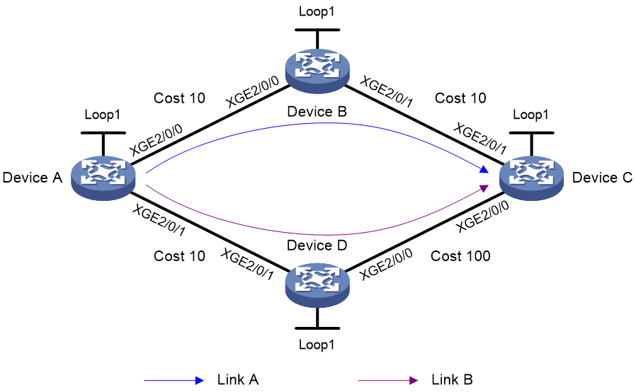
Table 1 Interface and IP address assignment
|
Device |
Interface |
IP address |
Device |
Interface |
IP address |
|
Device A |
Loop1 |
1::1/128 |
Device B |
Loop1 |
2::2/128 |
|
|
XGE2/0/0 |
2000:1::1/64 |
|
XGE2/0/0 |
2000:1::2/64 |
|
|
XGE2/0/1 |
2000:4::1/64 |
|
XGE2/0/1 |
2000:2::2/64 |
|
Device C |
Loop1 |
3::3/128 |
Device D |
Loop1 |
4::4/128 |
|
|
XGE2/0/0 |
2000:3::3/64 |
|
XGE2/0/0 |
2000:3::4/64 |
|
|
XGE2/0/1 |
2000:2::3/64 |
|
XGE2/0/1 |
2000:4::4/64 |
Procedure
1. Configure IPv6 addresses and prefixes for interfaces. (Details not shown.)
2. Configure Device A:
# Configure IPv6 IS-IS to achieve network level connectivity and set the IS-IS cost style to wide.
<DeviceA> system-view
[DeviceA] isis 1
[DeviceA-isis-1] network-entity 00.0000.0000.0001.00
[DeviceA-isis-1] cost-style wide
[DeviceA-isis-1] address-family ipv6
[DeviceA-isis-1-ipv6] quit
[DeviceA-isis-1] quit
[DeviceA] interface ten-gigabitethernet 2/0/0
[DeviceA-Ten-GigabitEthernet2/0/0] isis ipv6 enable 1
[DeviceA-Ten-GigabitEthernet2/0/0] isis cost 10
[DeviceA-Ten-GigabitEthernet2/0/0] quit
[DeviceA] interface ten-gigabitethernet 2/0/1
[DeviceA-Ten-GigabitEthernet2/0/1] isis ipv6 enable 1
[DeviceA-Ten-GigabitEthernet2/0/1] isis cost 10
[DeviceA-Ten-GigabitEthernet2/0/1] quit
[DeviceA] interface loopback 1
[DeviceA-LoopBack1] isis ipv6 enable 1
[DeviceA-LoopBack1] quit
# Enable SRv6 and configure a locator.
[DeviceA] segment-routing ipv6
[DeviceA-segment-routing-ipv6] locator aaa ipv6-prefix 11:: 64 static 32
[DeviceA-segment-routing-ipv6-locator-aaa] quit
[DeviceA-segment-routing-ipv6] quit
# Configure IPv6 IS-IS TI-LFA FRR and enable SR microloop avoidance.
[DeviceA] isis 1
[DeviceA-isis-1] address-family ipv6
[DeviceA-isis-1-ipv6] fast-reroute lfa
[DeviceA-isis-1-ipv6] fast-reroute ti-lfa
[DeviceA-isis-1-ipv6] fast-reroute microloop-avoidance enable
[DeviceA-isis-1-ipv6] segment-routing microloop-avoidance enable
# Apply the locator to the IPv6 IS-IS process.
[DeviceA-isis-1-ipv6] segment-routing ipv6 locator aaa
[DeviceA-isis-1-ipv6] quit
[DeviceA-isis-1] quit
3. Configure Device B:
# Configure IPv6 IS-IS to achieve network level connectivity and set the IS-IS cost style to wide.
<DeviceB> system-view
[DeviceB] isis 1
[DeviceB-isis-1] network-entity 00.0000.0000.0002.00
[DeviceB-isis-1] cost-style wide
[DeviceB-isis-1] address-family ipv6
[DeviceB-isis-1-ipv6] quit
[DeviceB-isis-1] quit
[DeviceB] interface ten-gigabitethernet 2/0/0
[DeviceB-Ten-GigabitEthernet2/0/0] isis ipv6 enable 1
[DeviceB-Ten-GigabitEthernet2/0/0] isis cost 10
[DeviceB-Ten-GigabitEthernet2/0/0] quit
[DeviceB] interface ten-gigabitethernet 2/0/1
[DeviceB-Ten-GigabitEthernet2/0/1] isis ipv6 enable 1
[DeviceB-Ten-GigabitEthernet2/0/1] isis cost 10
[DeviceB-Ten-GigabitEthernet2/0/1] quit
[DeviceB] interface loopback 1
[DeviceB-LoopBack1] isis ipv6 enable 1
[DeviceB-LoopBack1] quit
# Enable SRv6 and configure a locator.
[DeviceB] segment-routing ipv6
[DeviceB-segment-routing-ipv6] locator bbb ipv6-prefix 22:: 64 static 32
[DeviceB-segment-routing-ipv6-locator-bbb] quit
[DeviceB-segment-routing-ipv6] quit
# Configure IPv6 IS-IS TI-LFA FRR.
[DeviceB] isis 1
[DeviceB-isis-1] address-family ipv6
[DeviceB-isis-1-ipv6] fast-reroute lfa
[DeviceB-isis-1-ipv6] fast-reroute ti-lfa
# Apply the locator to the IPv6 IS-IS process.
[DeviceB-isis-1-ipv6] segment-routing ipv6 locator bbb
[DeviceB-isis-1-ipv6] quit
[DeviceB-isis-1] quit
4. Configure Device C:
# Configure IPv6 IS-IS to achieve network level connectivity and set the IS-IS cost style to wide.
<DeviceC> system-view
[DeviceC] isis 1
[DeviceC-isis-1] network-entity 00.0000.0000.0003.00
[DeviceC-isis-1] cost-style wide
[DeviceC-isis-1] address-family ipv6
[DeviceC-isis-1-ipv6] quit
[DeviceC-isis-1] quit
[DeviceC] interface ten-gigabitethernet 2/0/0
[DeviceC-Ten-GigabitEthernet2/0/0] isis ipv6 enable 1
[DeviceC-Ten-GigabitEthernet2/0/0] isis cost 100
[DeviceC-Ten-GigabitEthernet2/0/0] quit
[DeviceC] interface ten-gigabitethernet 2/0/1
[DeviceC-Ten-GigabitEthernet2/0/1] isis ipv6 enable 1
[DeviceC-Ten-GigabitEthernet2/0/1] isis cost 10
[DeviceC-Ten-GigabitEthernet2/0/1] quit
[DeviceC] interface loopback 1
[DeviceC-LoopBack1] isis ipv6 enable 1
[DeviceC-LoopBack1] quit
# Enable SRv6 and configure a locator.
[DeviceC] segment-routing ipv6
[DeviceC-segment-routing-ipv6] locator ccc ipv6-prefix 33:: 64 static 32
[DeviceC-segment-routing-ipv6-locator-ccc] quit
[DeviceC-segment-routing-ipv6] quit
# Configure IPv6 IS-IS TI-LFA FRR.
[DeviceC] isis 1
[DeviceC-isis-1] address-family ipv6
[DeviceC-isis-1-ipv6] fast-reroute lfa
[DeviceC-isis-1-ipv6] fast-reroute ti-lfa
# Apply the locator to the IPv6 IS-IS process.
[DeviceC-isis-1-ipv6] segment-routing ipv6 locator ccc
[DeviceC-isis-1-ipv6] quit
[DeviceC-isis-1] quit
5. Configure Device D:
# Configure IPv6 IS-IS to achieve network level connectivity and set the IS-IS cost style to wide.
<DeviceD> system-view
[DeviceD] isis 1
[DeviceD-isis-1] network-entity 00.0000.0000.0004.00
[DeviceD-isis-1] cost-style wide
[DeviceD-isis-1] address-family ipv6
[DeviceD-isis-1-ipv6] quit
[DeviceD-isis-1] quit
[DeviceD] interface ten-gigabitethernet 2/0/0
[DeviceD-Ten-GigabitEthernet2/0/0] isis ipv6 enable 1
[DeviceD-Ten-GigabitEthernet2/0/0] isis cost 100
[DeviceD-Ten-GigabitEthernet2/0/0] quit
[DeviceD] interface ten-gigabitethernet 2/0/1
[DeviceD-Ten-GigabitEthernet2/0/1] isis ipv6 enable 1
[DeviceD-Ten-GigabitEthernet2/0/1] isis cost 10
[DeviceD-Ten-GigabitEthernet2/0/1] quit
[DeviceD] interface loopback 1
[DeviceD-LoopBack1] isis ipv6 enable 1
[DeviceD-LoopBack1] quit
# Enable SRv6 and configure a locator.
[DeviceD] segment-routing ipv6
[DeviceD-segment-routing-ipv6] locator ddd ipv6-prefix 44:: 64 static 32
[DeviceD-segment-routing-ipv6-locator-ddd] quit
[DeviceD-segment-routing-ipv6] quit
# Configure IPv6 IS-IS TI-LFA FRR.
[DeviceD] isis 1
[DeviceD-isis-1] address-family ipv6
[DeviceD-isis-1-ipv6] fast-reroute lfa
[DeviceD-isis-1-ipv6] fast-reroute ti-lfa
# Apply the locator to the IPv6 IS-IS process.
[DeviceD-isis-1-ipv6] segment-routing ipv6 locator ddd
[DeviceD-isis-1-ipv6] quit
[DeviceD-isis-1] quit
Verifying the configuration
# Display IPv6 IS-IS routing information for 3::3/128.
[DeviceA] display isis route ipv6 3::3 128 verbose
Route information for IS-IS(1)
------------------------------
Level-1 IPv6 forwarding table
-----------------------------
IPv6 dest : 3::3/128
Flag : R/L/- Cost : 20
Admin tag : - Src count : 2
Nexthop : FE80::4449:7CFF:FEE0:206
NexthopFlag : -
Interface : XGE2/0/0
TI-LFA:
Interface : XGE2/0/1
BkNextHop : FE80::4449:91FF:FE42:407
LsIndex : 0x80000001
Backup label stack(top->bottom): {44::1:0:1}
Nib ID : 0x24000006
Flags: D-Direct, R-Added to Rib, L-Advertised in LSPs, U-Up/Down Bit Set
The output shows TI-LFA backup next hop information.
