- Table of Contents
-
- H3C WA7539 Access Point Installation Guide-5W100
- 00-Preface
- 01-Installing the device
- 02-Logging in to the device
- 03-Appendix A AP views and technical specifications
- 04-Appendix B LEDs and buttons
- 05-Appendix C Optional transceiver modules
- 06-Appendix D Connecting the hybrid copper-fiber cable
- 07-Appendix E Cabling recommendations
- Related Documents
-
| Title | Size | Download |
|---|---|---|
| 07-Appendix E Cabling recommendations | 194.02 KB |
7 Appendix E Cabling recommendations
Arrange cabling based on the actual situation of the installation environment and the equipment room, for example, locations of distribution cabinets, AC power receptacles, and lightning protection boxes. All connected cable joints must be neatly arranged in a place where they are not easily touched.
General cabling requirements
Minimum bending radius requirement for cables
· For a power cord, communication cable, or flat cable, the bending radius must be 5 times greater than the outer diameter of the cable after the cable is secured to the device. If the cable will be frequently bent or plugged in and out, the minimum bending radius must be 7 times the outer diameter of the cable.
· For a coaxial cable, the bending radius must be 7 times greater than the outer diameter of the cable after the cable is secured to the device. If the cable will be frequently bent or plugged in and out, the minimum bending radius must be 10 times the outer diameter of the cable.
· For a high-speed cable, for example, an SFP+ cable, the bending radius must be 5 times greater than the outer diameter of the cable. If the cable will be frequently bent or plugged in and out, the minimum bending radius must be 10 times the outer diameter of the cable.
Minimum bending radius requirement for optical fibers
· To place an optical fiber in a fiber tray, make sure the diameter of the fiber tray is not less than 25 times the diameter of the optical fiber.
· To move an optical fiber, make sure the diameter of the fiber tray is not less than 20 times the diameter of the optical fiber.
· To deploy an optical fiber, make sure the diameter of the fiber tray is not less than 10 times the diameter of the optical fiber.
The diameter of an optical fiber is the diameter of the outer sheath of the optical fiber. The diameter of a single-core optical fiber is typically 0.9 mm (0.04 in), 2.0 mm (0.08 in), or 3 mm (0.12 in).
Correct use of labels
Before you bundle a cable, fill in the label correctly and paste it on the appropriate position of the cable, typically 20 mm (0.79 in) away from the cable connector.
Cable management guidelines
When you route and bundle up cables, follow these guidelines:
· Bind and route the cables neatly inside the rack, and make sure they are not kinked or bent.
Figure7-1 Correct and incorrect cable binding
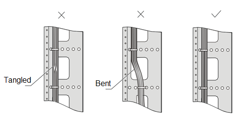
· Route different types of cables (for example, power cords and signal cables) separately. If they are close to one another, cross them over one another. If you route them in parallel, make sure the space between a power cord bundle and a signal cable bundle is a minimum of 30 mm (1.18 in).
· The cable management brackets and cable routing slots, inside or outside the rack, are smooth and do not have sharp edges or tips.
· When you route cables through sharp sheet metal penetration points or along sharp edges of mechanical parts, use bushings or take any other action to protect the cables from being cut or abraded. The sheet metal penetration points must be smooth and fully rounded.
· Use the correct type of ties to bind the cables. Do not bind cables with joined ties. The following types of ties are available: 100 × 2.5 mm (3.94 × 0.10 in), 150 × 3.6 mm (5.91 × 0.14 in), 300 × 3.6 mm (11.81 × 0.14 in), 530 × 9 mm (20.87 × 0.35 in), and 580 × 13 mm (22.83 × 0.51 in).
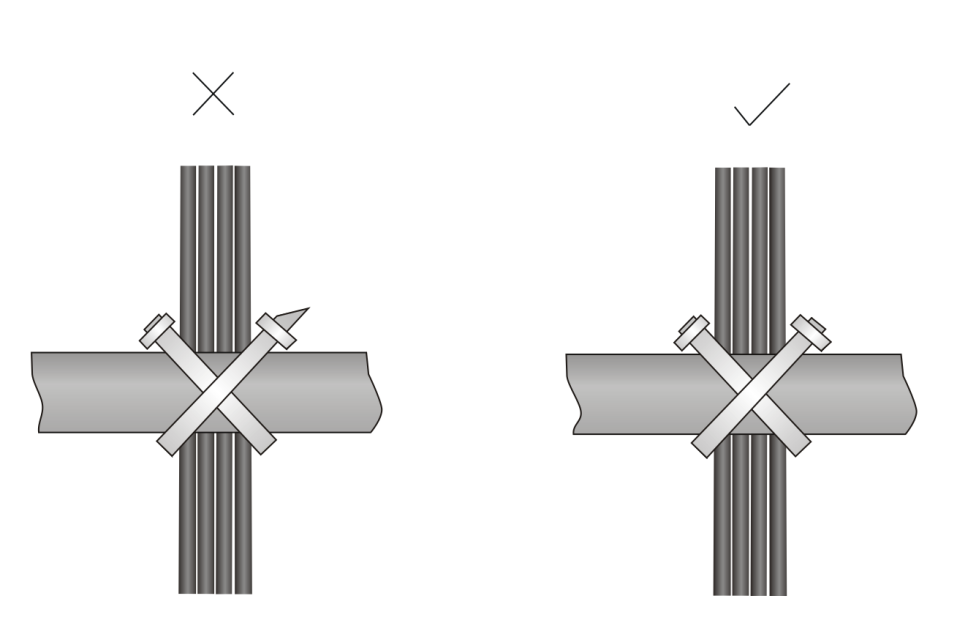
· After binding the cables, cut the excess from the ties, leaving no sharp or angular tips. See Figure7-2.
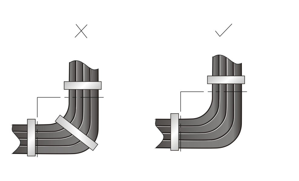
· When you bend cables, bind them as shown in Figure7-3. To avoid excessive stress causing cable core break, do not tie up the cables in the bending area.
Figure7-3 Binding cables where they must be bent
· Route, bind, and attach excess cables for easy, safe maintenance activities and correct operations.
· Do not tie 220 V or –48 V power cords to slide rails.
· When you connect a cable to an articulated part, for example, when you connect a grounding cable to a cabinet door, leave enough slack in cables and make sure they are not stressed from any movement of the part.
· Cables must be protected at points where they might rub or come in contact with sharp edges or heated areas. Use high temperature cables near heat sources.
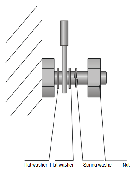
· Securely fasten cables and take adequate measures to prevent loose connections.
Figure7-4 Securely fastening cables
· Fasten heavy or rigid power cords at the connectors to relief stress.
· Do not use tapping screws to fasten the connecting terminals.
· Bind together cables that are the same type and routed in the same direction.
Table7-1 lists the cable bundling specifications.
Table7-1 Tie-binding parameters
|
Cable bundle diameter (mm) |
Space between bundles (mm) |
|
10 |
80 to 150 |
|
10 to 30 |
150 to 200 |
|
30 |
200 to 300 |
· Do not tie cables or bundles in a knot.
· The metal parts of the crimped cold-pressed terminal blocks (such as air switch) cannot protrude beyond the blocks.
