- Table of Contents
-
- 03-Layer 2—LAN Switching Configuration Examples
- 01-Ethernet Link Aggregation Configuration Examples
- 02-M-LAG Configuration Examples
- 03-MAC Address Table Configuration Examples
- 04-MVRP Configuration Examples
- 05-Port Isolation Configuration Examples
- 06-S-MLAG Configuration Examples
- 07-Spanning Tree Configuration Examples
- 08-VLAN Configuration Examples
- 09-VLAN Tagging Configuration Examples
- Related Documents
-
| Title | Size | Download |
|---|---|---|
| 08-VLAN Configuration Examples | 153.01 KB |
Contents
Example: Configuring port-based VLANs
Applicable hardware and software versions
Example: Configuring the super VLAN
Applicable hardware and software versions
Configuration restrictions and guidelines
Example: Configuring the private VLAN
Applicable hardware and software versions
Configuration restrictions and guidelines
Example: Configuring the voice VLAN
Applicable hardware and software versions
Configuration restrictions and guidelines
Configuring 802.1X authentication
Introduction
This document provides examples of configuring the port-based VLAN, super VLAN, private VLAN, and voice VLAN.
Prerequisites
The configuration examples in this document were created and verified in a lab environment, and all the devices were started with the factory default configuration. When you are working on a live network, make sure you understand the potential impact of every command on your network.
This document assumes that you have basic knowledge of VLANs.
Example: Configuring port-based VLANs
Network configuration
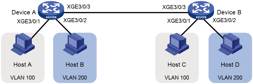
As shown in Figure 1:
· Host A and Host C belong to Department A. VLAN 100 is assigned to Department A.
· Host B and Host D belong to Department B. VLAN 200 is assigned to Department B.
Configure port-based VLANs so that hosts only in the same department can communicate with each other.
Applicable hardware and software versions
The following matrix shows the hardware and software versions to which this configuration example is applicable:
|
Hardware |
Software version |
|
S12500G-AF |
Release 8053P05 and later |
|
S12500CR |
Release 8053P05 and later |
|
S10500X-G |
Release 7753P05 and later |
|
S7500X-G |
Release 7753P05 and later |
Procedures
# Create VLAN 100, and assign Ten-GigabitEthernet 3/0/1 to VLAN 100.
[DeviceA-vlan100] port ten-gigabitethernet 3/0/1
[DeviceA-vlan100] quit
# Create VLAN 200, and assign Ten-GigabitEthernet 3/0/2 to VLAN 200.
[DeviceA-vlan200] port ten-gigabitethernet 3/0/2
[DeviceA-vlan200] quit
# Configure Ten-GigabitEthernet 3/0/3 as a trunk port, and assign it to VLANs 100 and 200.
[DeviceA] interface ten-gigabitethernet 3/0/3
[DeviceA-Ten-GigabitEthernet3/0/3] port link-type trunk
[DeviceA-Ten-GigabitEthernet3/0/3] port trunk permit vlan 100 200
2. Configure Device B in the same way Device A is configured. (Details not shown.)
3. Configure hosts:
a. Configure Host A and Host C to be on the same IP subnet. For example, 192.168.100.0/24.
b. Configure Host B and Host D to be on the same IP subnet. For example, 192.168.200.0/24.
Verifying the configuration
# Verify that Host B and Host D can ping each other, but they both fail to ping Host A or Host C. (Details not shown.)
# Display information about VLANs 100 and 200 on Device A.
[DeviceA-Ten-GigabitEthernet3/0/3] display vlan 100
VLAN ID: 100
VLAN type: Static
Route interface: Not configured
Description: VLAN 0100
Name: VLAN 0100
Tagged ports:
Ten-GigabitEthernet3/0/3
Untagged ports:
Ten-GigabitEthernet3/0/1
[DeviceA-Ten-GigabitEthernet3/0/3] display vlan 200
VLAN ID: 200
VLAN type: Static
Route interface: Not configured
Description: VLAN 0200
Name: VLAN 0200
Tagged ports:
Ten-GigabitEthernet3/0/3
Untagged ports:
Ten-GigabitEthernet3/0/2
The output shows that:
· Ten-GigabitEthernet 3/0/3 and Ten-GigabitEthernet 3/0/1 permit packets from 100 to pass through.
· Ten-GigabitEthernet 3/0/3 and Ten-GigabitEthernet 3/0/2 permit packets from 200 to pass through.
Configuration files
Configuration files on both Device B and Device A are the same. The following configuration files use Device A as an example.
#
vlan 100
#
vlan 200
#
interface Ten-GigabitEthernet3/0/1
port link-mode bridge
port access vlan 100
#
interface Ten-GigabitEthernet3/0/2
port link-mode bridge
port access vlan 200
#
interface Ten-GigabitEthernet3/0/3
port link-mode bridge
port link-type trunk
port trunk permit vlan 1 100 200
#
Example: Configuring the super VLAN
Network configuration
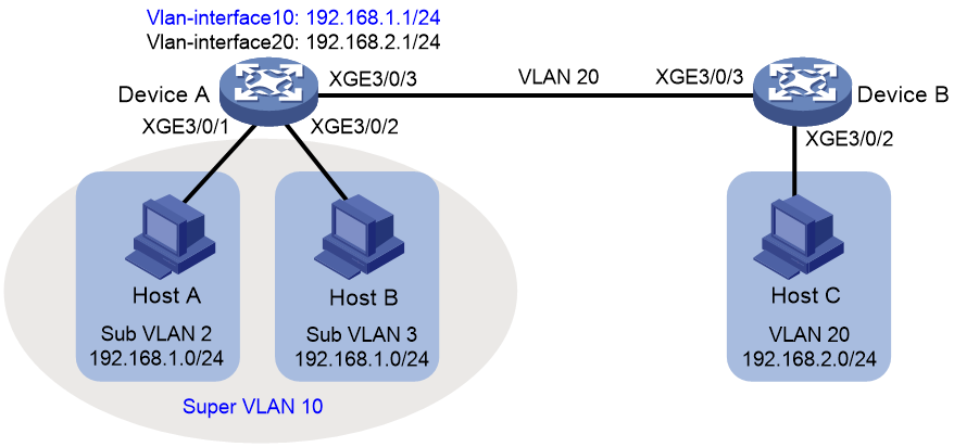
As shown in Figure 2:
· Users in VLAN 2 access the network through Ten-GigabitEthernet 3/0/1 of Device A.
· Users in VLAN 3 access the network through Ten-GigabitEthernet 3/0/2 of Device A.
· Ten-GigabitEthernet 3/0/3 of Device A and Ten-GigabitEthernet 3/0/1 of Device B are in VLAN 20.
· Users in VLAN 20 use the gateway address 192.168.2.1 and IP addresses on the IP network segment 192.168.2.0/24.
Configure a super VLAN to meet the following requirements:
· Users in VLAN 2 and VLAN 3 use the gateway address 192.168.1.1 and IP addresses on the IP network segment 192.168.1.0/24.
· Users in VLAN 2, VLAN 3, and VLAN 20 are isolated at Layer 2 but interoperable at Layer 3.
Applicable hardware and software versions
The following matrix shows the hardware and software versions to which this configuration example is applicable:
|
Hardware |
Software version |
|
S12500G-AF |
Release 8053P05 and later |
|
S12500CR |
Release 8053P05 and later |
|
S10500X-G |
Release 7753P05 and later |
|
S7500X-G |
Release 7753P05 and later |
Configuration restrictions and guidelines
For the S12500G-AF switch series , only the SF interface modules support Super VLAN.
For the S7500X-G switch series, only the SC modules prefixed with LSCM2 and the SD interface modules support Super VLAN.
A super VLAN does not have physical ports. A VLAN that has physical ports cannot be configured as a super VLAN.
Procedures
Configuring Device A
# Create VLAN 10 and configure it as a super VLAN.
<DeviceA> system-view
[DeviceA] vlan 10
[DeviceA-vlan10] supervlan
[DeviceA-vlan10] quit
# Create VLAN 2, and assign Ten-GigabitEthernet 3/0/1 to VLAN 2.
[DeviceA] vlan 2
[DeviceA-vlan2] port ten-gigabitethernet 3/0/1
[DeviceA-vlan2] quit
# Create VLAN 3, and assign Ten-GigabitEthernet 3/0/2 to VLAN 3.
[DeviceA] vlan 3
[DeviceA-vlan3] port ten-gigabitethernet 3/0/2
[DeviceA-vlan3] quit
# Associate super VLAN 10 with VLANs 2 and 3.
[DeviceA] vlan 10
[DeviceA-vlan10] subvlan 2 3
[DeviceA-vlan10] quit
# Create VLAN-interface 10, and assign IP address 192.168.1.1 to it.
[DeviceA] interface vlan-interface 10
[DeviceA-Vlan-interface10] ip address 192.168.1.1 24
# Enable local proxy ARP on VLAN-interface 10.
[DeviceA-Vlan-interface10] local-proxy-arp enable
[DeviceA-Vlan-interface10] quit
# Create VLAN 20.
[DeviceA] vlan 20
[DeviceA-vlan20] quit
# Configure Ten-GigabitEthernet 3/0/3 as a trunk port, and remove the port from VLAN 1.
[DeviceA] interface ten-gigabitethernet 3/0/3
[DeviceA-Ten-GigabitEthernet3/0/3] port link-type trunk
[DeviceA-Ten-GigabitEthernet3/0/3] undo port trunk permit vlan 1
# Assign Ten-GigabitEthernet 3/0/3 to VLAN 20.
[DeviceA-Ten-GigabitEthernet3/0/3] port trunk permit vlan 20
[DeviceA-Ten-GigabitEthernet3/0/3] quit
# Create VLAN-interface 20, and assign IP address 192.168.2.1 to it.
[DeviceA] interface Vlan-interface 20
[DeviceA-Vlan-interface20] ip address 192.168.2.1 24
[DeviceA-Vlan-interface20] quit
Configuring Device B
# Create VLAN 20.
[DeviceB] vlan 20
[DeviceB-vlan20] quit
# Configure Ten-GigabitEthernet 3/0/1 as a trunk port, and remove the port from VLAN 1.
[DeviceB] interface ten-gigabitethernet 3/0/1
[DeviceB-Ten-GigabitEthernet3/0/1] port link-type trunk
[DeviceB-Ten-GigabitEthernet3/0/1] undo port trunk permit vlan 1
# Assign Ten-GigabitEthernet 3/0/1 to VLAN 20.
[DeviceB-Ten-GigabitEthernet3/0/1] port trunk permit vlan 20
[DeviceB-Ten-GigabitEthernet3/0/1] quit
# Assign Ten-GigabitEthernet 3/0/2 to VLAN 20.
[DeviceB] vlan 20
[DeviceB-vlan20] port ten-gigabitethernet 3/0/2
[DeviceB-vlan20] quit
Verifying the configuration
# Verify the super VLAN configuration.
[DeviceA] display supervlan
Super VLAN ID: 10
Sub-VLAN ID: 2-3
VLAN ID: 10
VLAN type: Static
It is a super VLAN.
Route interface: Configured
IPv4 address: 192.168.1.1
IPv4 subnet mask: 255.255.255.0
Description: VLAN 0010
Name: VLAN 0010
Tagged ports: none
Untagged ports: none
VLAN ID: 2
VLAN type: Static
It is a sub-VLAN.
Route interface: Configured
IPv4 address: 192.168.1.1
IPv4 subnet mask: 255.255.255.0
Description: VLAN 0002
Name: VLAN 0002
Tagged ports: none
Untagged ports:
Ten-GigabitEthernet3/0/1
VLAN ID: 3
VLAN type: Static
It is a sub-VLAN.
Route interface: Configured
IPv4 address: 192.168.1.1
IPv4 subnet mask: 255.255.255.0
Description: VLAN 0003
Name: VLAN 0003
Tagged ports: none
Untagged ports:
Ten-GigabitEthernet3/0/2
# Verify that Host A and Host B can ping each other. In the ARP table of Host A, the IP address of Host B corresponds to the MAC address of VLAN-interface 10. In the ARP table of Host B, the IP address of Host A corresponds to the MAC address of VLAN-interface 10. (Details not shown.)
# Verify that Host A and Host C can ping each other. In the ARP table of Host A, no entry about Host C exists. In the ARP table of Host C, no entry about Host A exists. (Details not shown.)
# Verify that Host B and Host C can ping each other. In the ARP table of Host B, no entry about Host C exists. In the ARP table of Host C, no entry about Host B exists. (Details not shown.)
Configuration files
· Device A:
#
vlan 2
#
vlan 3
#
vlan 10
supervlan
subvlan 2 3
#
vlan 20
#
interface Vlan-interface10
ip address 192.168.1.1 255.255.255.0
local-proxy-arp enable
#
interface Vlan-interface20
ip address 192.168.2.1 255.255.255.0
#
interface Ten-GigabitEthernet3/0/1
port link-mode bridge
port access vlan 2
#
interface Ten-GigabitEthernet3/0/2
port link-mode bridge
port access vlan 3
#
interface Ten-GigabitEthernet3/0/3
port link-mode bridge
port link-type trunk
undo port trunk permit vlan 1
port trunk permit vlan 20
#
· Device B:
#
vlan 20
#
interface Ten-GigabitEthernet3/0/1
port link-mode bridge
port link-type trunk
undo port trunk permit vlan 1
port trunk permit vlan 20
#
interface Ten-GigabitEthernet3/0/2
port link-mode bridge
port access vlan 20
#
Example: Configuring the private VLAN
Network configuration
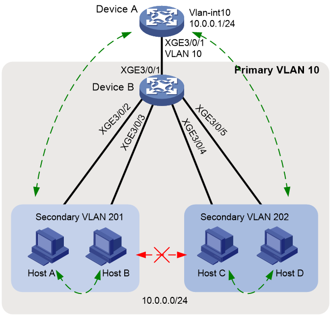
As shown in Figure 3:
· The aggregation-layer device Device A assigns VLAN 10 to Device B. Hosts access the network through VLAN-interface 10.
· Users connected to Device B are on the same subnet 10.0.0.0/24.
· Host A and Host B are in the Marketing department. Host C and Host D are in the Finance department.
Configure the private VLAN feature to meet the following requirements:
· Device A is only aware of the primary VLAN 10.
· Hosts in the same secondary VLAN are interoperable at Layer 2.
· Hosts in different secondary VLANs are isolated at Layer 2.
Requirements analysis
The private VLAN configuration is required only on Device B.
Applicable hardware and software versions
The following matrix shows the hardware and software versions to which this configuration example is applicable:
|
Hardware |
Software version |
|
S12500G-AF |
Release 8053P05 and later |
|
S12500CR |
Release 8053P05 and later |
|
S10500X-G |
Release 7753P05 and later |
|
S7500X-G |
Release 7753P05 and later |
Configuration restrictions and guidelines
For the S12500G-AF switch series, only the SF interface modules support Private VLAN.
For the S7500X-G switch series, only the SC modules prefixed with LSCM2 and the SD interface modules support Private VLAN.
The system default VLAN (VLAN 1) does not support the private VLAN configuration.
Procedures
Configuring Device B
# Create VLAN 10 and configure it as a primary VLAN.
<DeviceB> system-view
[DeviceB] vlan 10
[DeviceB-vlan10] private-vlan primary
[DeviceB-vlan10] quit
# Create VLANs 201 and 202.
[DeviceB] vlan 201 to 202
# Associate primary VLAN 10 with secondary VLANs 201 and 202.
[DeviceB] vlan 10
[DeviceB-vlan10] private-vlan secondary 201 to 202
[DeviceB-vlan10] quit
# Configure the uplink port Ten-GigabitEthernet 3/0/1 as a promiscuous port of VLAN 10.
[DeviceB] interface ten-gigabitethernet 3/0/1
[DeviceB-Ten-GigabitEthernet3/0/1] port private-vlan 10 promiscuous
[DeviceB-Ten-GigabitEthernet3/0/1] quit
# Assign the downlink ports Ten-GigabitEthernet 3/0/2 and Ten-GigabitEthernet 3/0/3 to VLAN 201 as host ports.
[DeviceB] interface range ten-gigabitethernet 3/0/2 to ten-gigabitethernet 3/0/3
[DeviceB-if-range] port access vlan 201
[DeviceB-if-range] port private-vlan host
[DeviceB-if-range] quit
# Assign the downlink ports Ten-GigabitEthernet 3/0/4 and Ten-GigabitEthernet 3/0/5 to VLAN 202 as host ports.
[DeviceB] interface range ten-gigabitethernet 3/0/4 to ten-gigabitethernet 3/0/5
[DeviceB-if-range] port access vlan 202
[DeviceB-if-range] port private-vlan host
[DeviceB-if-range] quit
Configuring Device A
# Create VLAN 10.
<DeviceA> system-view
[DeviceA] vlan 10
[DeviceA] quit
# Assign Ten-GigabitEthernet 3/0/1 to VLAN 10.
[DeviceA] interface ten-gigabitethernet 3/0/1
[DeviceA-Ten-GigabitEthernet3/0/1] port access vlan 10
[DeviceA-Ten-GigabitEthernet3/0/1] quit
# Create VLAN-interface 10, and assign IP address 10.0.0.1 to it.
[DeviceA] interface vlan-interface 10
[DeviceA-Vlan-interface10] ip address 10.0.0.1 24
[DeviceA-Vlan-interface10] quit
Verifying the configuration
# Verify that Device A can ping Host A, Host B, Host C, and Host D successfully. (Details not shown.)
# Display the ARP table of Device A.
[DeviceA] display arp
Type: S-Static D-Dynamic O-Openflow R-Rule M-Multiport I-Invalid
IP address MAC address VLAN/VSI Interface/Link ID Aging Type
10.0.0.2 d485-64a1-7e4a 10 XGE3/0/1 19 D
10.0.0.3 7446-a0aa-7774 10 XGE3/0/1 19 D
10.0.0.4 6805-ca05-39ae 10 XGE3/0/1 20 D
10.0.0.5 6805-ca05-414e 10 XGE3/0/1 20 D
# Display the private VLAN configuration on Device B.
[DeviceB] display private-vlan
Primary VLAN ID: 10
Secondary VLAN ID: 201-202
VLAN ID: 10
VLAN type: Static
Private VLAN type: Primary
Route interface: Not configured
Description: VLAN 0010
Name: VLAN 0010
Tagged ports: None
Untagged ports:
Ten-GigabitEthernet3/0/1 Ten-GigabitEthernet3/0/2
Ten-GigabitEthernet3/0/3 Ten-GigabitEthernet3/0/4
Ten-GigabitEthernet3/0/5
VLAN ID: 201
VLAN type: Static
Private VLAN type: Secondary
Route interface: Not configured
Description: VLAN 0201
Name: VLAN 0201
Tagged ports: None
Untagged ports:
Ten-GigabitEthernet3/0/1 Ten-GigabitEthernet3/0/2
Ten-GigabitEthernet3/0/3
VLAN ID: 202
VLAN type: Static
Private VLAN type: Secondary
Route interface: Not configured
Description: VLAN 0202
Name: VLAN 0202
Tagged ports: None
Untagged ports:
Ten-GigabitEthernet3/0/1 Ten-GigabitEthernet3/0/4
Ten-GigabitEthernet3/0/5
The output shows that:
· The promiscuous port Ten-GigabitEthernet3/0/1 is an untagged member of primary VLAN 10 and secondary VLANs 201 and 202.
· The host ports Ten-GigabitEthernet 3/0/2 and Ten-GigabitEthernet 3/0/3 are untagged members of secondary VLANs 201.
· The host ports Ten-GigabitEthernet 3/0/4 and Ten-GigabitEthernet 3/0/5 are untagged members of secondary VLANs 202.
# Verify that Hosts in the same secondary VLAN can ping each other, but they fail to ping hosts in the other secondary VLAN. (Details not shown.)
Configuration files
· Device B:
#
vlan 1
#
vlan 10
private-vlan primary
private-vlan secondary 201 to 202
#
vlan 201 to 202
#
interface Ten-GigabitEthernet3/0/1
port link-mode bridge
port link-type hybrid
undo port hybrid vlan 1
port hybrid vlan 10 201 to 202 untagged
port hybrid pvid vlan 10
port private-vlan 10 promiscuous
#
interface Ten-GigabitEthernet3/0/2
port link-mode bridge
port link-type hybrid
undo port hybrid vlan 1
port hybrid vlan 10 201 untagged
port hybrid pvid vlan 201
port private-vlan host
#
interface Ten-GigabitEthernet3/0/3
port link-mode bridge
port link-type hybrid
undo port hybrid vlan 1
port hybrid vlan 10 201 untagged
port hybrid pvid vlan 201
port private-vlan host
#
interface Ten-GigabitEthernet3/0/4
port link-mode bridge
port link-type hybrid
undo port hybrid vlan 1
port hybrid vlan 10 202 untagged
port hybrid pvid vlan 202
port private-vlan host
#
interface Ten-GigabitEthernet3/0/5
port link-mode bridge
port link-type hybrid
undo port hybrid vlan 1
port hybrid vlan 10 202 untagged
port hybrid pvid vlan 202
port private-vlan host
#
· Device A:
#
vlan 1
#
vlan 10
#
interface Vlan-interface10
ip address 10.0.0.1 255.255.255.0
#
interface Ten-GigabitEthernet3/0/1
port link-mode bridge
port access vlan 10
#
Example: Configuring the voice VLAN
Network configuration
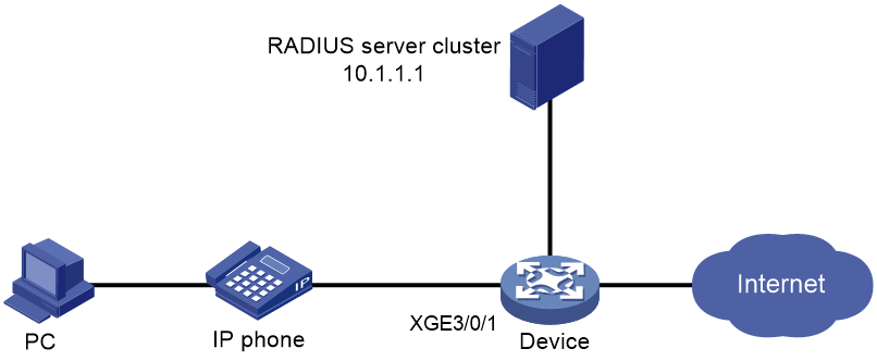
As shown in Figure 4, the device connects to an IP phone through Ten-GigabitEthernet3/0/1, and the IP phone sends tagged voice traffic. The device authenticates the IP phone through the RADIUS server. If the IP phone passes authentication, the IP phone is allowed to access the device. Configure voice VLAN 2 on the device. Configure LLDP to enable the IP phone to automatically come online after passing 802.1X authentication.
Configure voice VLAN to meet the following requirements:
· The IP phone automatically comes online after passing 802.1X authentication on Ten-GigabitEthernet 3/0/1.
· The IP phone can automatically come online and send voice traffic without manually configured voice VLAN MAC addresses on the device.
Configuration considerations
· By default, an IP phone supports LLDP.
· When enabling LLDP for autodiscovering IP phones, you must configure the network-policy TLV to advertise voice VLAN information on Ten-GigabitEthernet 3/0/1.
· Enable the automatic voice VLAN assignment mode.
· Configure IP addresses for interfaces.
Applicable hardware and software versions
The following matrix shows the hardware and software versions to which this configuration example is applicable:
|
Hardware |
Software version |
|
S12500G-AF |
Release 8053P05 and later |
|
S12500CR |
Release 8053P05 and later |
|
S10500X-G |
Release 7753P05 and later |
|
S7500X-G |
Release 7753P05 and later |
Configuration restrictions and guidelines
Whether the username sent to the RADIUS server includes the domain name depends on the RADIUS server configuration and whether the RADIUS server accepts usernames including domain names.
· If the server does not accept usernames including domain names or the service configured for user authentication on the server does not include a domain name, specify the username not to include the domain name (without-domain) on the device.
· If the server can accept usernames including domain names and the service configured for user authentication on the server includes a domain name, specify the username to include the domain name (with-domain) on the device.
Procedures
Configuring the voice VLAN
# Create VLAN 2.
<Device> system-view
[Device] vlan 2
[Device-vlan2] quit
# Enable LLDP globally.
[Device] lldp global enable
# Enable LLDP on Ten-GigabitEthernet 3/0/1, configure LLDP to operate in TxRx mode, and configure LLDP to advertise the voice VLAN ID.
[Device] interface ten-gigabitethernet 3/0/1
[Device-Ten-GigabitEthernet3/0/1] lldp enable
[Device-Ten-GigabitEthernet3/0/1] lldp admin-status txrx
[Device-Ten-GigabitEthernet3/0/1] lldp tlv-enable med-tlv network-policy 2
[Device-Ten-GigabitEthernet3/0/1] quit
# Enable the voice VLAN security mode, and set the voice VLAN aging timer to 30 minutes.
[Device] voice-vlan security enable
[Device] voice-vlan aging 30
# Enable LLDP for automatic IP phone discovery.
[Device] voice-vlan track lldp
# Configure Ten-GigabitEthernet 3/0/1 as a hybrid port, and configure the voice VLAN feature.
[Device] interface ten-gigabitethernet 3/0/1
[Device-Ten-GigabitEthernet3/0/1] port link-type hybrid
[Device-Ten-GigabitEthernet3/0/1] voice-vlan mode auto
[Device-Ten-GigabitEthernet3/0/1] voice-vlan 2 enable
Configuring 802.1X authentication
# Configure the RADIUS server, add user accounts, and make sure accounting, authorization, and accounting run properly for users. (Details not shown.)
# Create a RADIUS scheme. Configure the primary authentication and accounting servers and the keys for secure RADIUS authentication and accounting communication. Specify the device to remove the ISP domain name in the username sent to the RADIUS server.
[Device] radius scheme radius1
[Device-radius-radius1] primary authentication 10.1.1.1
[Device-radius-radius1] primary accounting 10.1.1.1
[Device-radius-radius1] key authentication simple name
[Device-radius-radius1] key accounting simple money
[Device-radius-radius1] user-name-format without-domain
[Device-radius-radius1] quit
# Create ISP domain bbb, and configure 802.1X users to use RADIUS scheme radius1 for authentication, authorization, and accounting.
[Device] domain bbb
[Device-isp-bbb] authentication lan-access radius-scheme radius1
[Device-isp-bbb] authorization lan-access radius-scheme radius1
[Device-isp-bbb] accounting lan-access radius-scheme radius1
[Device-isp-bbb] quit
# Configure 802.1X on Ten-GigabitEthernet 3/0/1, and specify mandatory 802.1X authentication domain bbb on the interface.
[Device] interface ten-gigabitethernet 3/0/1
[Device-Ten-GigabitEthernet3/0/1] dot1x
[Device-Ten-GigabitEthernet3/0/1] dot1x mandatory-domain bbb
# Enable the 802.1X multicast trigger feature. (Optional. By default, the 802.1X multicast trigger feature is enabled.)
[Device-Ten-GigabitEthernet3/0/1] dot1x multicast-trigger
[Device-Ten-GigabitEthernet3/0/1] quit
# Enable the 802.1x feature globally.
[Device] dot1x
# Configure the 802.1X client. (Details not shown.)
If you use an H3C iNode 802.1X client, for the backup authentication method local authentication to succeed, make sure the Upload version info option is not selected in the 802.1X connection properties.
Verifying the configuration
# Display 802.1X authentication information.
[Device] display dot1x interface ten-gigabitethernet 3/0/1
Global 802.1X parameters:
802.1X authentication : Enabled
CHAP authentication : Enabled
Max-tx period : 30 s
Handshake period : 15 s
Offline detect period : 300 s
Quiet timer : Disabled
Quiet period : 60 s
Supp timeout : 30 s
Server timeout : 100 s
Reauth period : 3600 s
Max auth requests : 2
User aging period for Auth-Fail VLAN : 1000 s
User aging period for Auth-Fail VSI : 1000 s
User aging period for critical VLAN : 1000 s
User aging period for critical VSI : 1000 s
User aging period for guest VLAN : 1000 s
User aging period for guest VSI : 1000 s
EAD assistant function : Disabled
EAD timeout : 30 min
Domain delimiter : @
Online 802.1X wired users : 1
Ten-GigabitEthernet3/0/1 is link-up
802.1X authentication : Enabled
Handshake : Enabled
Handshake reply : Disabled
Handshake security : Disabled
Offline detection : Disabled
Unicast trigger : Disabled
Periodic reauth : Disabled
Port role : Authenticator
Authorization mode : Auto
Port access control : MAC-based
Multicast trigger : Enabled
Mandatory auth domain : Not configured
Guest VLAN : Not configured
Auth-Fail VLAN : Not configured
Critical VLAN : Not configured
Critical voice VLAN : Disabled
Add Guest VLAN delay : Disabled
Re-auth server-unreachable : Logoff
Max online users : 4294967295
User IP freezing : Disabled
Reauth period : 0 s
Send Packets Without Tag : Disabled
Max Attempts Fail Number : 0
Guest VSI : Not configured
Auth-Fail VSI : Not configured
Critical VSI : Not configured
Add Guest VSI delay : Disabled
User aging : Enabled
Server-recovery online-user-sync : Enabled
Auth-Fail EAPOL : Disabled
Critical EAPOL : Disabled
EAPOL packets: Tx 0, Rx 0
Sent EAP Request/Identity packets : 0
EAP Request/Challenge packets: 0
EAP Success packets: 0
EAP Failure packets: 0
Received EAPOL Start packets : 0
EAPOL LogOff packets: 0
EAP Response/Identity packets : 0
EAP Response/Challenge packets: 0
Error packets: 0
Online 802.1X users: 1
After the IP phone enters the correct username and password and then comes online, use the display dot1x connection command to display the connections of online users.
# Display the voice VLAN state.
[Device] display voice-vlan state
Current voice VLANs: 2
Voice VLAN security mode: Security
Voice VLAN aging time: 30 minutes
Voice VLAN enabled ports and their modes:
Port VLAN Mode CoS DSCP
XGE3/0/1 2 Auto 6 46
Configuration files
#
voice-vlan aging 30
voice-vlan track lldp
#
dot1x
#
lldp global enable
#
vlan 1
#
vlan 2
#
interface Ten-GigabitEthernet3/0/1
port link-mode bridge
port link-type hybrid
port hybrid vlan 1 untagged
voice-vlan 2 enable
lldp tlv-enable med-tlv network-policy 2
dot1x
dot1x mandatory-domain bbb
#
radius scheme radius1
primary authentication 10.1.1.1
primary accounting 10.1.1.1
key authentication cipher $c$3$/gxrbATUfK4BbF+73EQiCzBM7cwP86o=
key accounting cipher $c$3$mq8b76RILWQr2lH7NTtvE9+7O0v7vd1H
user-name-format without-domain
#
radius scheme system
user-name-format without-domain
#
domain bbb
accounting login radius-scheme radius1
authentication lan-access radius-scheme radius1
authorization lan-access radius-scheme radius1