- Table of Contents
-
- 03-Layer 2—LAN Switching Configuration Examples
- 01-Ethernet Link Aggregation Configuration Examples
- 02-M-LAG Configuration Examples
- 03-MAC Address Table Configuration Examples
- 04-MVRP Configuration Examples
- 05-Port Isolation Configuration Examples
- 06-S-MLAG Configuration Examples
- 07-Spanning Tree Configuration Examples
- 08-VLAN Configuration Examples
- 09-VLAN Tagging Configuration Examples
- Related Documents
-
| Title | Size | Download |
|---|---|---|
| 02-M-LAG Configuration Examples | 304.25 KB |
Contents
Example: Configuring M-LAG at the access Layer
Applicable hardware and software versions
M-LAG restrictions and guidelines
VRRP restrictions and guidelines
Example: Configuring M-LAG at the distribution Layer
Applicable hardware and software versions
M-LAG restrictions and guidelines
VRRP restrictions and guidelines
Example: Configure IPv4 and IPv6 dual-active gateways on an M-LAG system
Applicable hardware and software versions
M-LAG restrictions and guidelines
Introduction
This document provides M-LAG configuration examples.
Multichassis Link Aggregation (M-LAG) virtualizes two physical devices into one system through multichassis link aggregation.
Prerequisites
The configuration examples were created and verified in a lab environment, and all the devices were started with the factory default configuration. When you are working on a live network, make sure you understand the potential impact of every command on your network.
The following information is provided based on the assumption that you have basic knowledge of M-LAG.
Example: Configuring M-LAG at the access Layer
Network configuration
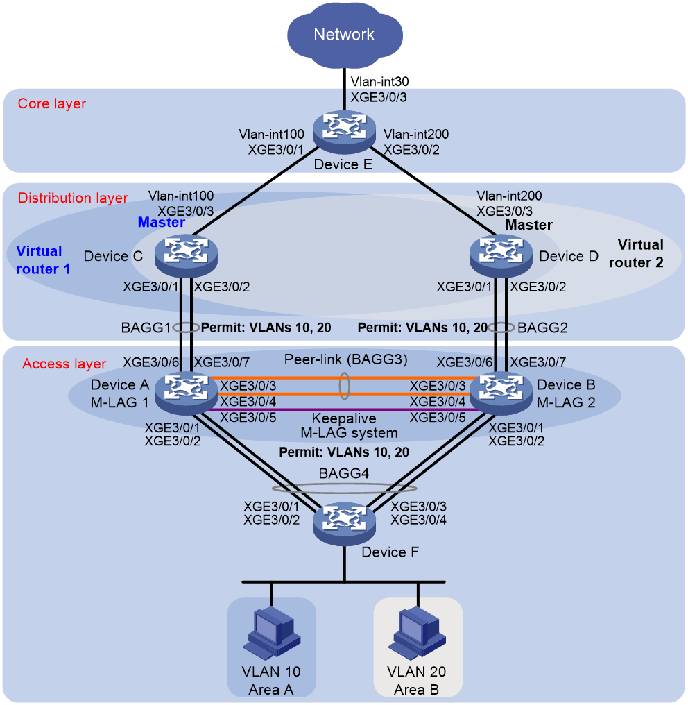
As shown in Figure 1:
· Configure Device A and Device B as an M-LAG system to establish one multichassis aggregate link with Device F and one with Device C and Device D.
· Set up a keepalive link between Ten-GigabitEthernet 3/0/5 of Device A and Ten-GigabitEthernet 3/0/5 of Device B, and exclude the interfaces from the shutdown action by M-LAG MAD.
· Configure two VRRP groups on Device C and Device D to provide gateway services for VLAN 10 and VLAN 20.
¡ Configure VRRP group 1 to provide gateway services for hosts in VLAN 10 (Area A). Add Device C and Device D to the group as the master and backup devices, respectively.
¡ Configure VRRP group 2 to provide gateway services for hosts in VLAN 20 (Area B). Add Device D and Device C to the group as the master and backup devices, respectively.
· Configure OSPF on Device C, Device D, and Device E for the hosts to communicate with external networks at Layer 3.
|
Device |
Interface |
IP address |
Device |
Interface |
IP address |
|
Device A |
XGE 3/0/5 |
1.1.1.1/24 |
Device B |
XGE3/0/5 |
1.1.1.2/24 |
|
Device C |
VLAN-interface 100 |
100.1.1.1/24 |
Device D |
VLAN-interface 100 |
200.1.1.1/24 |
|
|
VLAN-interface 10 |
10.1.1.1/24 |
|
VLAN-interface 10 |
10.1.1.2/24 |
|
|
VLAN-interface 20 |
20.1.1.1/24 |
|
VLAN-interface 20 |
20.1.1.2/24 |
|
|
Virtual IP 1 |
10.1.1.100/24 |
|
Virtual IP 1 |
10.1.1.100/24 |
|
|
Virtual IP 2 |
20.1.1.100/24 |
|
Virtual IP 2 |
20.1.1.100/24 |
|
Device E |
VLAN-interface 100 |
100.1.1.2/24 |
|
|
|
|
|
VLAN-interface 200 |
200.1.1.2/24 |
|
|
|
|
|
VLAN-interface 30 |
30.1.1.1/24 |
|
|
|
Analysis
For the secondary M-LAG device to monitor the state of the primary device, establish a Layer 3 keepalive link between the M-LAG member devices.
To balance traffic between two VRRP gateway devices, you can assign them to two VRRP groups with different priorities. In this example, Device C is assigned a higher priority than Device D in VRRP group 1 so Device C can become the master in this group. Device D is assigned a higher priority than Device C in VRRP group 2 so Device D can become the master in this group.
Applicable hardware and software versions
The following matrix shows the hardware and software versions to which this configuration example is applicable:
|
Hardware |
Software version |
|
S12500G-AF |
Release 8053P05 and later |
|
S12500CR |
Release 8053P05 and later |
|
S10500X-G |
Release 7753P05 and later |
|
S7500X-G |
Release 7753P05 and later |
Restrictions and guidelines
M-LAG restrictions and guidelines
For the M-LAG member devices to be identified as one M-LAG system, you must configure the same M-LAG system MAC address and M-LAG system priority on them. You must assign different M-LAG system numbers to the M-LAG member devices.
An M-LAG member device can have only one peer link.
For correct keepalive detection, you must exclude the interfaces used for keepalive detection from the shutdown action by M-LAG MAD.
VRRP restrictions and guidelines
You cannot specify the virtual IP address as any of the following IP addresses:
· All-zero address (0.0.0.0).
· Broadcast address (255.255.255.255).
· Loopback address.
· IP address of other than Class A, Class B, and Class C.
· Invalid IP address (for example, 0.0.0.1).
The virtual IP address of an IPv4 VRRP group must be on the same subnet as the downlink interface IP addresses of the VRRP group members to ensure successful traffic forwarding.
Procedures
Configuring Device A
# Configure M-LAG system settings.
<DeviceA> system-view
[DeviceA] m-lag system-mac 1-1-1
Changing the system MAC might flap the intra-portal link and cause M-LAG system setup failure. Continue? [Y/N]:y
[DeviceA] m-lag system-number 1
Changing the system number might flap the intra-portal link and cause M-LAG system setup failure. Continue? [Y/N]:y
[DeviceA] m-lag system-priority 123
Changing the system priority might flap the intra-portal link and cause M-LAG system setup failure. Continue? [Y/N]:y
# Configure M-LAG keepalive packet parameters.
[DeviceA] m-lag keepalive ip destination 1.1.1.2 source 1.1.1.1
# Configure Ten-GigabitEthernet 3/0/5 as a routed (Layer 3) interface and assign the interface an IP address. The IP address will be used as the source IP address of keepalive packets.
[DeviceA] interface ten-gigabitethernet 3/0/5
[DeviceA-Ten-GigabitEthernet3/0/5] port link-mode route
[DeviceA-Ten-GigabitEthernet3/0/5] ip address 1.1.1.1 24
[DeviceA-Ten-GigabitEthernet3/0/5] quit
# Exclude the interface used for M-LAG keepalive detection (Ten-GigabitEthernet 3/0/5) from the shutdown action by M-LAG MAD.
[DeviceA] m-lag mad exclude interface ten-gigabitethernet 3/0/5
# Create VLAN 10 and VLAN 20.
[DeviceA] vlan 10
[DeviceA-vlan10] quit
[DeviceA] vlan 20
[DeviceA-vlan20] quit
# Create Layer 2 dynamic aggregate interface Bridge-Aggregation 1.
[DeviceA] interface bridge-aggregation 1
[DeviceA-Bridge-Aggregation1] link-aggregation mode dynamic
[DeviceA-Bridge-Aggregation1] quit
# Assign Ten-GigabitEthernet 3/0/6 and Ten-GigabitEthernet 3/0/7 to aggregation group 1.
[DeviceA] interface ten-gigabitethernet 3/0/6
[DeviceA-Ten-GigabitEthernet3/0/6] port link-aggregation group 1
[DeviceA-Ten-GigabitEthernet3/0/6] quit
[DeviceA] interface ten-gigabitethernet 3/0/7
[DeviceA-Ten-GigabitEthernet3/0/7] port link-aggregation group 1
[DeviceA-Ten-GigabitEthernet3/0/7] quit
# Set the link type of Bridge-Aggregation 1 to trunk and assign it to VLAN 10 and VLAN 20.
[DeviceA] interface bridge-aggregation 1
[DeviceA-Bridge-Aggregation1] port link-type trunk
Configuring Ten-GigabitEthernet3/0/6 done.
Configuring Ten-GigabitEthernet3/0/7 done.
[DeviceA-Bridge-Aggregation1] port trunk permit vlan 10 20
Configuring Ten-GigabitEthernet3/0/6 done.
Configuring Ten-GigabitEthernet3/0/7 done.
[DeviceA-Bridge-Aggregation1] quit
# Create Layer 2 dynamic aggregate interface Bridge-Aggregation 3.
[DeviceA] interface bridge-aggregation 3
[DeviceA-Bridge-Aggregation3] link-aggregation mode dynamic
[DeviceA-Bridge-Aggregation3] quit
# Assign Ten-GigabitEthernet 3/0/3 and Ten-GigabitEthernet 3/0/4 to aggregation group 3.
[DeviceA] interface ten-gigabitethernet 3/0/3
[DeviceA-Ten-GigabitEthernet3/0/3] port link-aggregation group 3
[DeviceA-Ten-GigabitEthernet3/0/3] quit
[DeviceA] interface ten-gigabitethernet 3/0/4
[DeviceA-Ten-GigabitEthernet3/0/4] port link-aggregation group 3
[DeviceA-Ten-GigabitEthernet3/0/4] quit
# Specify Bridge-Aggregation 3 as the peer-link interface.
[DeviceA] interface bridge-aggregation 3
[DeviceA-Bridge-Aggregation3] port m-lag peer-link 1
[DeviceA-Bridge-Aggregation3] quit
# Create Layer 2 dynamic aggregate interface Bridge-Aggregation 4 and assign it to M-LAG group 4.
[DeviceA] interface bridge-aggregation 4
[DeviceA-Bridge-Aggregation4] link-aggregation mode dynamic
[DeviceA-Bridge-Aggregation4] port m-lag group 4
[DeviceA-Bridge-Aggregation4] quit
# Assign Ten-GigabitEthernet 3/0/1 and Ten-GigabitEthernet 3/0/2 to aggregation group 4.
[DeviceA] interface ten-gigabitethernet 3/0/1
[DeviceA-Ten-GigabitEthernet3/0/1] port link-aggregation group 4
[DeviceA-Ten-GigabitEthernet3/0/1] quit
[DeviceA] interface ten-gigabitethernet 3/0/2
[DeviceA-Ten-GigabitEthernet3/0/2] port link-aggregation group 4
[DeviceA-Ten-GigabitEthernet3/0/2] quit
# Set the link type of Bridge-Aggregation 4 to trunk and assign it to VLAN 10 and VLAN 20.
[DeviceA] interface bridge-aggregation 4
[DeviceA-Bridge-Aggregation4] port link-type trunk
Configuring Ten-GigabitEthernet3/0/1 done.
Configuring Ten-GigabitEthernet3/0/2 done.
[DeviceA-Bridge-Aggregation4] port trunk permit vlan 10 20
Configuring Ten-GigabitEthernet3/0/1 done.
Configuring Ten-GigabitEthernet3/0/2 done.
[DeviceA-Bridge-Aggregation4] quit
Configuring Device B
# Configure M-LAG system settings.
<DeviceB> system-view
[DeviceB] m-lag system-mac 1-1-1
Changing the system MAC might flap the intra-portal link and cause M-LAG system setup failure. Continue? [Y/N]:y
[DeviceB] m-lag system-number 2
Changing the system number might flap the intra-portal link and cause M-LAG system setup failure. Continue? [Y/N]:y
[DeviceB] m-lag system-priority 123
Changing the system priority might flap the intra-portal link and cause M-LAG system setup failure. Continue? [Y/N]:y
# Configure M-LAG keepalive packet parameters.
[DeviceB] m-lag keepalive ip destination 1.1.1.1 source 1.1.1.2
# Configure Ten-GigabitEthernet 3/0/5 as a routed (Layer 3) interface and assign the interface an IP address. The IP address will be used as the source IP address of keepalive packets.
[DeviceB] interface ten-gigabitethernet 3/0/5
[DeviceB-Ten-GigabitEthernet3/0/5] port link-mode route
[DeviceB-Ten-GigabitEthernet3/0/5] ip address 1.1.1.2 24
[DeviceB-Ten-GigabitEthernet3/0/5] quit
# Exclude the interface used for M-LAG keepalive detection (Ten-GigabitEthernet 3/0/5) from the shutdown action by M-LAG MAD.
[DeviceB] m-lag mad exclude interface ten-gigabitethernet 3/0/5
# Create VLAN 10 and VLAN 20.
[DeviceB] vlan 10
[DeviceB-vlan10] quit
[DeviceB] vlan 20
[DeviceB-vlan20] quit
# Create Layer 2 dynamic aggregate interface Bridge-Aggregation 2.
[DeviceB] interface bridge-aggregation 2
[DeviceB-Bridge-Aggregation2] link-aggregation mode dynamic
[DeviceB-Bridge-Aggregation2] quit
# Assign Ten-GigabitEthernet 3/0/6 and Ten-GigabitEthernet 3/0/7 to aggregation group 2.
[DeviceB] interface ten-gigabitethernet 3/0/6
[DeviceB-Ten-GigabitEthernet3/0/6] port link-aggregation group 2
[DeviceB-Ten-GigabitEthernet3/0/6] quit
[DeviceB] interface ten-gigabitethernet 3/0/7
[DeviceB-Ten-GigabitEthernet3/0/7] port link-aggregation group 2
[DeviceB-Ten-GigabitEthernet3/0/7] quit
# Set the link type of Bridge-Aggregation 2 to trunk and assign it to VLAN 10 and VLAN 20.
[DeviceB] interface bridge-aggregation 2
[DeviceB-Bridge-Aggregation2] port link-type trunk
Configuring Ten-GigabitEthernet3/0/6 done.
Configuring Ten-GigabitEthernet3/0/7 done.
[DeviceB-Bridge-Aggregation2] port trunk permit vlan 10 20
Configuring Ten-GigabitEthernet3/0/6 done.
Configuring Ten-GigabitEthernet3/0/7 done.
[DeviceB-Bridge-Aggregation2] quit
# Create Layer 2 dynamic aggregate interface Bridge-Aggregation 3.
[DeviceB] interface bridge-aggregation 3
[DeviceB-Bridge-Aggregation3] link-aggregation mode dynamic
[DeviceB-Bridge-Aggregation3] quit
# Assign Ten-GigabitEthernet 3/0/3 and Ten-GigabitEthernet 3/0/4 to aggregation group 3.
[DeviceB] interface ten-gigabitethernet 3/0/3
[DeviceB-Ten-GigabitEthernet3/0/3] port link-aggregation group 3
[DeviceB-Ten-GigabitEthernet3/0/3] quit
[DeviceB] interface ten-gigabitethernet 3/0/4
[DeviceB-Ten-GigabitEthernet3/0/4] port link-aggregation group 3
[DeviceB-Ten-GigabitEthernet3/0/4] quit
# Specify Bridge-Aggregation 3 as the peer-link interface.
[DeviceB] interface bridge-aggregation 3
[DeviceB-Bridge-Aggregation3] port m-lag peer-link 1
[DeviceB-Bridge-Aggregation3] quit
# Create Layer 2 dynamic aggregate interface Bridge-Aggregation 4 and assign it to M-LAG group 4.
[DeviceB] interface bridge-aggregation 4
[DeviceB-Bridge-Aggregation4] link-aggregation mode dynamic
[DeviceB-Bridge-Aggregation4] port m-lag group 4
[DeviceB-Bridge-Aggregation4] quit
# Assign Ten-GigabitEthernet 3/0/1 and Ten-GigabitEthernet 3/0/2 to aggregation group 4.
[DeviceB] interface ten-gigabitethernet 3/0/1
[DeviceB-Ten-GigabitEthernet3/0/1] port link-aggregation group 4
[DeviceB-Ten-GigabitEthernet3/0/1] quit
[DeviceB] interface ten-gigabitethernet 3/0/2
[DeviceB-Ten-GigabitEthernet3/0/2] port link-aggregation group 4
[DeviceB-Ten-GigabitEthernet3/0/2] quit
# Set the link type of Bridge-Aggregation 4 to trunk and assign it to VLAN 10 and VLAN 20.
[DeviceB] interface bridge-aggregation 4
[DeviceB-Bridge-Aggregation4] port link-type trunk
Configuring Ten-GigabitEthernet3/0/1 done.
Configuring Ten-GigabitEthernet3/0/2 done.
[DeviceB-Bridge-Aggregation4] port trunk permit vlan 10 20
Configuring Ten-GigabitEthernet3/0/1 done.
Configuring Ten-GigabitEthernet3/0/2 done.
[DeviceB-Bridge-Aggregation4] quit
Configuring Device C
# Create VLAN 10, VLAN 20, and VLAN 100.
<DeviceC> system-view
[DeviceC] vlan 10
[DeviceC-vlan10] quit
[DeviceC] vlan 20
[DeviceC-vlan20] quit
[DeviceC] vlan 100
# Assign Ten-GigabitEthernet 3/0/3 to VLAN 100.
[DeviceC] vlan 100
[DeviceC-vlan100] port ten-gigabitethernet 3/0/3
[DeviceC-vlan100] quit
# Create Layer 2 dynamic aggregate interface Bridge-Aggregation 1.
[DeviceC] interface bridge-aggregation 1
[DeviceC-Bridge-Aggregation1] link-aggregation mode dynamic
[DeviceC-Bridge-Aggregation1] quit
# Assign Ten-GigabitEthernet 3/0/1 and Ten-GigabitEthernet3/0/2 to aggregation group 1.
[DeviceC] interface range ten-gigabitethernet 3/0/1 to ten-gigabitethernet 3/0/2
[DeviceC-if-range] port link-aggregation group 1
[DeviceC-if-range] quit
# Set the link type of Bridge-Aggregation 1 to trunk and assign it to VLAN 10 and VLAN 20.
[DeviceC] interface bridge-aggregation 1
[DeviceC-Bridge-Aggregation1] port link-type trunk
Configuring Ten-GigabitEthernet3/0/1 done.
Configuring Ten-GigabitEthernet3/0/2 done.
[DeviceC-Bridge-Aggregation1] port trunk permit vlan 10 20
Configuring Ten-GigabitEthernet3/0/1 done.
Configuring Ten-GigabitEthernet3/0/2 done.
[DeviceC-Bridge-Aggregation1] quit
# Create uplink interface VLAN-interface 100 and assign it an IP address.
[DeviceC] interface vlan-interface 100
[DeviceC-Vlan-interface100] ip address 100.1.1.1 24
[DeviceC-Vlan-interface100] quit
# Create VLAN-interface 10 and VLAN-interface 20 and assign an IP address to each of them.
[DeviceC] interface vlan-interface 10
[DeviceC-vlan-interface10] ip address 10.1.1.1 24
[DeviceC-vlan-interface10] quit
[DeviceC] interface vlan-interface 20
[DeviceC-vlan-interface20] ip address 20.1.1.1 24
[DeviceC-vlan-interface20] quit
# Create VRRP group 1 on VLAN-interface 10 and set its virtual IP address to 10.1.1.100.
[DeviceC] interface vlan-interface 10
[DeviceC-Vlan-interface10] vrrp vrid 1 virtual-ip 10.1.1.100
# Set the priority of Device C to 200 for it to become the master in VRRP group 1.
[DeviceC-Vlan-interface10] vrrp vrid 1 priority 200
[DeviceC-Vlan-interface10] quit
# Create VRRP group 2 on VLAN-interface 20 and set its virtual IP address to 20.1.1.100.
[DeviceC] interface vlan-interface 20
[DeviceC-Vlan-interface20] vrrp vrid 2 virtual-ip 20.1.1.100
[DeviceC-vlan-interface20] quit
# Configure Device C to operate in preemptive mode in VRRP group 1. Set the preemption delay to 500 centiseconds to avoid frequent status switchover.
[DeviceC] interface vlan-interface 10
[DeviceC-Vlan-interface10] vrrp vrid 1 preempt-mode delay 500
[DeviceC-Vlan-interface10] quit
# Create track entry 1 to monitor the upstream link status of Ten-GigabitEthernet 3/0/3.
[DeviceC] track 1 interface ten-gigabitethernet 3/0/3
# Configure Device C in VRRP group 1 to monitor track entry 1, and decrease its priority by 150 when the track entry transits to Negative.
[DeviceC] interface vlan-interface 10
[DeviceC-Vlan-interface10] vrrp vrid 1 track 1 priority reduced 150
[DeviceC-Vlan-interface10] quit
# Configure OSPF.
[DeviceC] ospf
[DeviceC-ospf-1] area 0
[DeviceC-ospf-1-area-0.0.0.0] network 10.1.1.0 0.0.0.255
[DeviceC-ospf-1-area-0.0.0.0] network 20.1.1.0 0.0.0.255
[DeviceC-ospf-1-area-0.0.0.0] network 100.1.1.0 0.0.0.255
[DeviceC-ospf-1-area-0.0.0.0] quit
[DeviceC-ospf-1] quit
Configuring Device D
# Create VLAN 10, VLAN 20, and VLAN 200.
<DeviceD> system-view
[DeviceD] vlan 10
[DeviceD-vlan10] quit
[DeviceD] vlan 20
[DeviceD-vlan20] quit
[DeviceD] vlan 200
# Assign Ten-GigabitEthernet 3/0/3 to VLAN 200.
[DeviceD] vlan 200
[DeviceD-vlan200] port ten-gigabitethernet 3/0/3
[DeviceD-vlan200] quit
# Create Layer 2 dynamic aggregate interface Bridge-Aggregation 2.
[DeviceD] interface bridge-aggregation 2
[DeviceD-Bridge-Aggregation2] link-aggregation mode dynamic
[DeviceD-Bridge-Aggregation2] quit
# Assign Ten-GigabitEthernet 3/0/1 and Ten-GigabitEthernet 3/0/2 to aggregation group 2.
[DeviceD] interface range ten-gigabitethernet 3/0/1 to ten-gigabitethernet 3/0/2
[DeviceD-if-range] port link-aggregation group 2
[DeviceD-if-range] quit
# Set the link type of Bridge-Aggregation 2 to trunk and assign it to VLAN 10 and VLAN 20.
[DeviceD] interface bridge-aggregation 2
[DeviceD-Bridge-Aggregation2] port link-type trunk
Configuring Ten-GigabitEthernet3/0/1 done.
Configuring Ten-GigabitEthernet3/0/2 done.
[DeviceD-Bridge-Aggregation2] port trunk permit vlan 10 20
Configuring Ten-GigabitEthernet3/0/1 done.
Configuring Ten-GigabitEthernet3/0/2 done.
[DeviceD-Bridge-Aggregation2] quit
# Create uplink interface VLAN-interface 200 and assign it an IP address.
[DeviceD] interface vlan-interface 200
[DeviceD-Vlan-interface200] ip address 200.1.1.1 24
[DeviceD-Vlan-interface200] quit
# Create VLAN-interface 10 and VLAN-interface 20 and assign an IP address to each of them.
[DeviceD] interface vlan-interface 10
[DeviceD-vlan-interface10] ip address 10.1.1.2 24
[DeviceD-vlan-interface10] quit
[DeviceD] interface vlan-interface 20
[DeviceD-vlan-interface20] ip address 20.1.1.2 24
[DeviceD-vlan-interface20] quit
# Create VRRP group 1 on VLAN-interface 10 and set its virtual IP address to 10.1.1.100.
[DeviceD] interface vlan-interface 10
[DeviceD-Vlan-interface10] vrrp vrid 1 virtual-ip 10.1.1.100
[DeviceD-vlan-interface10] quit
# Create VRRP group 2 on VLAN-interface 20 and set its virtual IP address to 20.1.1.100.
[DeviceD] interface vlan-interface 20
[DeviceD-Vlan-interface20] vrrp vrid 2 virtual-ip 20.1.1.100
# Set the priority of Device D to 200 for it to become the master in VRRP group 2.
[DeviceD-Vlan-interface20] vrrp vrid 2 priority 200
# Configure Device D to operate in preemptive mode in VRRP group 2. Set the preemption delay to 500 centiseconds to avoid frequent status switchover.
[DeviceD-Vlan-interface20] vrrp vrid 2 preempt-mode delay 500
[DeviceD-Vlan-interface20] quit
# Create track entry 2 to monitor the upstream link status of Ten-GigabitEthernet 3/0/3.
[DeviceD] track 2 interface ten-gigabitethernet 3/0/3
# Configure Device D in VRRP group 2 to monitor track entry 2, and decrease its priority by 150 when the track entry transits to Negative.
[DeviceD] interface vlan-interface 20
[DeviceD-Vlan-interface20] vrrp vrid 2 track 2 priority reduced 150
[DeviceD-Vlan-interface20] quit
# Configure OSPF.
[DeviceD] ospf
[DeviceD-ospf-1] area 0
[DeviceD-ospf-1-area-0.0.0.0] network 10.1.1.0 0.0.0.255
[DeviceD-ospf-1-area-0.0.0.0] network 20.1.1.0 0.0.0.255
[DeviceD-ospf-1-area-0.0.0.0] network 200.1.1.0 0.0.0.255
[DeviceD-ospf-1-area-0.0.0.0] quit
[DeviceD-ospf-1] quit
Configuring Device E
# Create VLAN 100 and assign Ten-GigabitEthernet 3/0/1 to the VLAN.
<DeviceE> system-view
[DeviceE] vlan 100
[DeviceE-vlan100] port ten-gigabitethernet 3/0/1
[DeviceE-vlan100] quit
# Create VLAN-interface 100 and assign it an IP address.
[DeviceE] interface vlan-interface 100
[DeviceE-vlan-interface100] ip address 100.1.1.2 24
[DeviceE-vlan-interface100] quit
# Create VLAN 200 and assign Ten-GigabitEthernet 3/0/2 to the VLAN.
[DeviceE] vlan 200
[DeviceE-vlan200] port ten-gigabitethernet 3/0/2
[DeviceE-vlan200] quit
# Create VLAN-interface 200 and assign it an IP address.
[DeviceE] interface vlan-interface 200
[DeviceE-vlan-interface200] ip address 200.1.1.2 24
[DeviceE-vlan-interface200] quit
# Create VLAN 30 and assign Ten-GigabitEthernet 3/0/3 to the VLAN.
[DeviceE] vlan 30
[DeviceE-vlan30] port ten-gigabitethernet 3/0/3
[DeviceE-vlan30] quit
# Create VLAN-interface 30 and assign it an IP address.
[DeviceE] interface vlan-interface 30
[DeviceE-vlan-interface30] ip address 30.1.1.1 24
[DeviceE-vlan-interface30] quit
# Configure OSPF.
[DeviceD] ospf
[DeviceD-ospf-1] area 0
[DeviceD-ospf-1-area-0.0.0.0] network 100.1.1.0 0.0.0.255
[DeviceD-ospf-1-area-0.0.0.0] network 200.1.1.0 0.0.0.255
[DeviceD-ospf-1-area-0.0.0.0] network 30.1.1.0 0.0.0.255
[DeviceD-ospf-1-area-0.0.0.0] quit
[DeviceD-ospf-1] quit
Configuring Device F
# Create VLAN 10 and VLAN 20.
[DeviceF] vlan 10
[DeviceF-vlan10] quit
[DeviceF] vlan 20
[DeviceF-vlan20] quit
# Create Layer 2 dynamic aggregate interface Bridge-Aggregation 4.
[DeviceF] interface bridge-aggregation 4
[DeviceF-Bridge-Aggregation4] link-aggregation mode dynamic
[DeviceF-Bridge-Aggregation4] quit
# Assign Ten-GigabitEthernet 3/0/1 through Ten-GigabitEthernet 3/0/4 to aggregation group 4.
[DeviceF] interface range ten-gigabitethernet 3/0/1 to ten-gigabitethernet 3/0/4
[DeviceF-if-range] port link-aggregation group 4
[DeviceF-if-range] quit
# Set the link type of Bridge-Aggregation 4 to trunk and assign it to VLAN 10 and VLAN 20.
[DeviceF] interface bridge-aggregation 4
[DeviceF-Bridge-Aggregation4] port link-type trunk
Configuring Ten-GigabitEthernet3/0/1 done.
Configuring Ten-GigabitEthernet3/0/2 done.
Configuring Ten-GigabitEthernet3/0/3 done.
Configuring Ten-GigabitEthernet3/0/4 done.
[DeviceF-Bridge-Aggregation4] port trunk permit vlan 10 20
Configuring Ten-GigabitEthernet3/0/1 done.
Configuring Ten-GigabitEthernet3/0/2 done.
Configuring Ten-GigabitEthernet3/0/3 done.
Configuring Ten-GigabitEthernet3/0/4 done.
[DeviceF-Bridge-Aggregation4] quit
Verifying the configuration
# Verify that Device A and Device B have formed an M-LAG system.
[DeviceA] display m-lag summary
Flags: A -- Aggregate interface down, B -- No peer M-LAG interface configured
C -- Configuration consistency check failed
Peer-link interface: BAGG3
Peer-link interface state (cause): UP
Keepalive link state (cause): UP
M-LAG interface information
M-LAG IF M-LAG group Local state (cause) Peer state Remaining down time(s)
BAGG4 4 UP UP -
[DeviceA] display m-lag verbose
Flags: A -- Home_Gateway, B -- Neighbor_Gateway, C -- Other_Gateway,
D -- PeerLink_Activity, E -- DRCP_Timeout, F -- Gateway_Sync,
G -- Port_Sync, H -- Expired
Peer-link interface/Peer-link interface ID: BAGG3/1
State: UP
Cause: -
Local DRCP flags/Peer DRCP flags: ABDFG/ABDFG
Local Selected ports (index): XGE3/0/3 (2), XGE3/0/4 (5)
Peer Selected ports indexes: 2, 5
M-LAG interface/M-LAG group ID: BAGG4/4
Local M-LAG interface state: UP
Peer M-LAG interface state: UP
M-LAG group state: UP
Local M-LAG interface down cause: -
Remaining M-LAG DOWN time: -
Local M-LAG interface LACP MAC: Config=0001-0001-0001, Effective=0001-0001-0001
Peer M-LAG interface LACP MAC: Config=0001-0001-0001, Effective=0001-0001-0001
Local M-LAG interface LACP priority: Config=200, Effective=200
Peer M-LAG interface LACP priority: Config=200, Effective=200
Local DRCP flags/Peer DRCP flags: ABDFG/ABDFG
Local Selected ports (index): XGE3/0/1 (16385), XGE3/0/2 (16388)
Peer Selected ports indexes: 32769, 32772
# Verify that all member ports of aggregation group 4 are in Selected state on Device F, which indicates a successful link aggregation between the M-LAG system and Device F.
[DeviceF] display link-aggregation verbose
Loadsharing Type: Shar -- Loadsharing, NonS -- Non-Loadsharing
Port Status: S -- Selected, U -- Unselected, I -- Individual
Port: A -- Auto port, M -- Management port, R -- Reference port
Flags: A -- LACP_Activity, B -- LACP_Timeout, C -- Aggregation,
D -- Synchronization, E -- Collecting, F -- Distributing,
G -- Defaulted, H -- Expired
Aggregate Interface: Bridge-Aggregation4
Creation Mode: Manual
Aggregation Mode: Dynamic
Loadsharing Type: Shar
Management VLANs: None
System ID: 0x8000, 1eba-3c46-0300
Local:
Port Status Priority Index Oper-Key Flag
XGE3/0/1 S 32768 1 1 {ACDEF}
XGE3/0/2 S 32768 2 1 {ACDEF}
XGE3/0/3 S 32768 3 1 {ACDEF}
XGE3/0/4 S 32768 4 1 {ACDEF}
Remote:
Actor Priority Index Oper-Key SystemID Flag
XGE3/0/1(R) 32768 16385 40004 0x7b , 0001-0001-0001 {ACDEF}
XGE3/0/2 32768 16388 40004 0x7b , 0001-0001-0001 {ACDEF}
XGE3/0/3 32768 32769 40004 0x7b , 0001-0001-0001 {ACDEF}
XGE3/0/4 32768 32772 40004 0x7b , 0001-0001-0001 {ACDEF}
# Verify that Device C is the master in VRRP group 1 and Device D is the master in VRRP group 2.
[DeviceC] display vrrp
IPv4 Virtual Router Information:
Running mode : Standard
Total number of virtual routers : 2
Interface VRID State Running Adver Auth Virtual
Pri Timer Type IP
---------------------------------------------------------------------
Vlan10 1 Master 200 100 None 10.1.1.100
Vlan20 2 Backup 100 100 None 20.1.1.100
[DeviceD] display vrrp
IPv4 Virtual Router Information:
Running mode : Standard
Total number of virtual routers : 2
Interface VRID State Running Adver Auth Virtual
Pri Timer Type IP
---------------------------------------------------------------------
Vlan10 1 Backup 100 100 None 10.1.1.100
Vlan20 2 Master 200 100 None 20.1.1.100
# Verify that Device E has established OSPF neighbor relationships with Device C and Device D.
[DeviceE] display ospf peer
OSPF Process 1 with Router ID 200.1.1.2
Neighbor Brief Information
Area: 0.0.0.0
Router ID Address Pri Dead-Time State Interface
100.1.1.1 100.1.1.1 1 35 Full/BM-LAG Vlan100
200.1.1.1 200.1.1.1 1 33 Full/BM-LAG Vlan200
# Verify that the host in Area A can ping VLAN-interface 30 (30.1.1.1) on Device E.
C:\Documents and Settings\Administrator>ping 30.1.1.1
Pinging 30.1.1.1 with 32 bytes of data:
Reply from 30.1.1.1: bytes=32 time=1ms TTL=126
Reply from 30.1.1.1: bytes=32 time=1ms TTL=126
Reply from 30.1.1.1: bytes=32 time=1ms TTL=126
Reply from 30.1.1.1: bytes=32 time=1ms TTL=126
Ping statistics for 30.1.1.1:
Packets: Sent = 4, Received = 4, Lost = 0 (0% loss),
Approximate round trip times in milli-seconds:
Minimum = 1ms, Maximum = 1ms, Average = 1ms
Configuration files
· Device A:
#
vlan 10
#
vlan 20
#
interface Bridge-Aggregation1
port link-type trunk
port trunk permit vlan 1 10 20
link-aggregation mode dynamic
#
interface Bridge-Aggregation3
port link-type trunk
port trunk permit vlan all
link-aggregation mode dynamic
port m-lag peer-link 1
#
interface Bridge-Aggregation4
port link-type trunk
port trunk permit vlan 1 10 20
link-aggregation mode dynamic
port m-lag group 4
#
interface Ten-GigabitEthernet3/0/5
port link-mode route
ip address 1.1.1.1 255.255.255.0
#
interface Ten-GigabitEthernet3/0/1
port link-mode bridge
port link-type trunk
port trunk permit vlan 1 10 20
port link-aggregation group 4
#
interface Ten-GigabitEthernet3/0/2
port link-mode bridge
port link-type trunk
port trunk permit vlan 1 10 20
port link-aggregation group 4
#
interface Ten-GigabitEthernet3/0/3
port link-mode bridge
port link-type trunk
port trunk permit vlan all
port link-aggregation group 3
#
interface Ten-GigabitEthernet3/0/4
port link-mode bridge
port link-type trunk
port trunk permit vlan all
port link-aggregation group 3
#
interface Ten-GigabitEthernet3/0/6
port link-mode bridge
port link-type trunk
port trunk permit vlan 1 10 20
port link-aggregation group 1
#
interface Ten-GigabitEthernet3/0/7
port link-mode bridge
port link-type trunk
port trunk permit vlan 1 10 20
port link-aggregation group 1
#
m-lag system-mac 0001-0001-0001
m-lag system-number 1
m-lag system-priority 123
m-lag keepalive ip destination 1.1.1.2 source 1.1.1.1
#
m-lag mad exclude interface Ten-GigabitEthernet3/0/5
#
· Device B:
#
vlan 10
#
vlan 20
#
interface Bridge-Aggregation2
port link-type trunk
port trunk permit vlan 1 10 20
link-aggregation mode dynamic
#
interface Bridge-Aggregation3
port link-type trunk
port trunk permit vlan all
link-aggregation mode dynamic
port m-lag peer-link 1
#
interface Bridge-Aggregation4
port link-type trunk
port trunk permit vlan 1 10 20
link-aggregation mode dynamic
port m-lag group 4
#
interface Ten-GigabitEthernet3/0/5
port link-mode route
ip address 1.1.1.2 255.255.255.0
#
interface Ten-GigabitEthernet3/0/1
port link-mode bridge
port link-type trunk
port trunk permit vlan 1 10 20
port link-aggregation group 4
#
interface Ten-GigabitEthernet3/0/2
port link-mode bridge
port link-type trunk
port trunk permit vlan 1 10 20
port link-aggregation group 4
#
interface Ten-GigabitEthernet3/0/3
port link-mode bridge
port link-type trunk
port trunk permit vlan all
port link-aggregation group 3
#
interface Ten-GigabitEthernet3/0/4
port link-mode bridge
port link-type trunk
port trunk permit vlan all
port link-aggregation group 3
#
interface Ten-GigabitEthernet3/0/6
port link-mode bridge
port link-type trunk
port trunk permit vlan 1 10 20
port link-aggregation group 2
#
interface Ten-GigabitEthernet3/0/7
port link-mode bridge
port link-type trunk
port trunk permit vlan 1 10 20
port link-aggregation group 2
#
m-lag system-mac 0001-0001-0001
m-lag system-number 2
m-lag system-priority 123
m-lag keepalive ip destination 1.1.1.1 source 1.1.1.2
#
m-lag mad exclude interface Ten-GigabitEthernet3/0/5
#
· Device C:
#
ospf 1
area 0.0.0.0
network 10.1.1.0 0.0.0.255
network 20.1.1.0 0.0.0.255
network 100.1.1.0 0.0.0.255
#
vlan 10
#
vlan 20
#
vlan 100
#
interface Bridge-Aggregation1
port link-type trunk
port trunk permit vlan 1 10 20
link-aggregation mode dynamic
#
interface Vlan-interface10
ip address 10.1.1.1 255.255.255.0
vrrp vrid 1 virtual-ip 10.1.1.100
vrrp vrid 1 priority 200
vrrp vrid 1 preempt-mode delay 500
vrrp vrid 1 track 1 priority reduced 150
#
interface Vlan-interface20
ip address 20.1.1.1 255.255.255.0
vrrp vrid 2 virtual-ip 20.1.1.100
#
interface Vlan-interface100
ip address 100.1.1.1 255.255.255.0
#
interface Ten-GigabitEthernet3/0/1
port link-mode bridge
port link-type trunk
port trunk permit vlan 1 10 20
port link-aggregation group 1
#
interface Ten-GigabitEthernet3/0/2
port link-mode bridge
port link-type trunk
port trunk permit vlan 1 10 20
port link-aggregation group 1
#
interface Ten-GigabitEthernet3/0/3
port link-mode bridge
port access vlan 100
#
track 1 interface Ten-GigabitEthernet3/0/3
#
· Device D:
#
ospf 1
area 0.0.0.0
network 10.1.1.0 0.0.0.255
network 20.1.1.0 0.0.0.255
network 200.1.1.0 0.0.0.255
#
vlan 10
#
vlan 20
#
vlan 200
#
interface Bridge-Aggregation2
port link-type trunk
port trunk permit vlan 1 10 20
link-aggregation mode dynamic
#
interface Vlan-interface10
ip address 10.1.1.2 255.255.255.0
vrrp vrid 1 virtual-ip 10.1.1.100
#
interface Vlan-interface20
ip address 20.1.1.2 255.255.255.0
vrrp vrid 2 virtual-ip 20.1.1.100
vrrp vrid 2 priority 200
vrrp vrid 2 preempt-mode delay 500
vrrp vrid 2 track 2 priority reduced 150
#
interface Vlan-interface200
ip address 200.1.1.1 255.255.255.0
#
interface Ten-GigabitEthernet3/0/1
port link-mode bridge
port link-type trunk
port trunk permit vlan 1 10 20
port link-aggregation group 2
#
interface Ten-GigabitEthernet3/0/2
port link-mode bridge
port link-type trunk
port trunk permit vlan 1 10 20
port link-aggregation group 2
#
interface Ten-GigabitEthernet3/0/3
port link-mode bridge
port access vlan 200
#
track 2 interface Ten-GigabitEthernet3/0/3
#
· Device E:
#
ospf 1
area 0.0.0.0
network 30.1.1.0 0.0.0.255
network 100.1.1.0 0.0.0.255
network 200.1.1.0 0.0.0.255
#
vlan 30
#
vlan 100
#
vlan 200
#
interface Vlan-interface30
ip address 30.1.1.1 255.255.255.0
#
interface Vlan-interface100
ip address 100.1.1.2 255.255.255.0
#
interface Vlan-interface200
ip address 200.1.1.2 255.255.255.0
#
interface Ten-GigabitEthernet3/0/1
port link-mode bridge
port access vlan 100
#
interface Ten-GigabitEthernet3/0/2
port link-mode bridge
port access vlan 200
#
interface Ten-GigabitEthernet3/0/3
port link-mode bridge
port access vlan 30
#
· Device F:
#
vlan 10
#
vlan 20
#
interface Bridge-Aggregation4
port link-type trunk
port trunk permit vlan 1 10 20
link-aggregation mode dynamic
#
interface Ten-GigabitEthernet3/0/1
port link-mode bridge
port link-type trunk
port trunk permit vlan 1 10 20
port link-aggregation group 4
#
interface Ten-GigabitEthernet3/0/2
port link-mode bridge
port link-type trunk
port trunk permit vlan 1 10 20
port link-aggregation group 4
#
interface Ten-GigabitEthernet3/0/3
port link-mode bridge
port link-type trunk
port trunk permit vlan 1 10 20
port link-aggregation group 4
#
interface Ten-GigabitEthernet3/0/4
port link-mode bridge
port link-type trunk
port trunk permit vlan 1 10 20
port link-aggregation group 4
#
Example: Configuring M-LAG at the distribution Layer
Network configuration
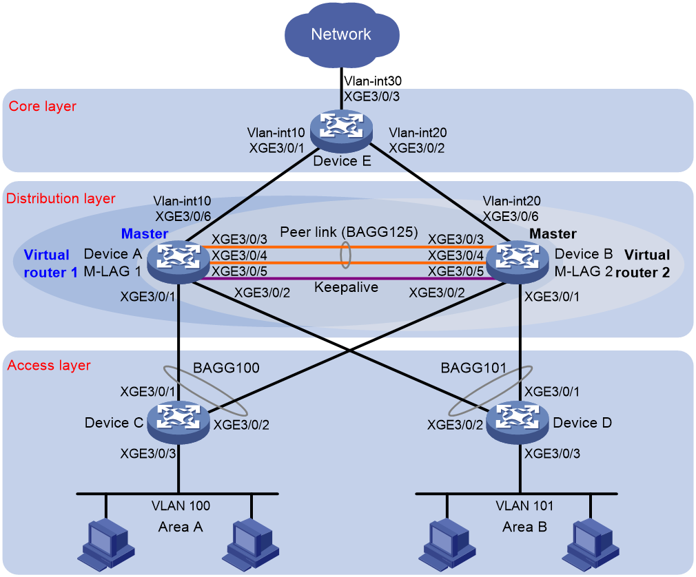
As shown in Figure 2:
· Configure Device A and Device B as an M-LAG system to establish one multichassis aggregate link with Device C and Device D.
· Set up a keepalive link between Ten-GigabitEthernet 3/0/5 of Device A and Ten-GigabitEthernet 3/0/5 of Device B, and exclude the interfaces from the shutdown action by M-LAG MAD.
· Configure two VRRP groups on Device A and Device B to provide gateway services for VLAN 100 and VLAN 101.
¡ Configure VRRP group 1 to provide gateway services for hosts in VLAN 100 (Area A). Add Device A and Device B to the group as the master and backup devices, respectively.
¡ Configure VRRP group 2 to provide gateway services for hosts in VLAN 101 (Area B). Add Device B and Device A to the group as the master and backup devices, respectively.
· Configure OSPF on Device A, Device B, and Device E for the hosts to communicate with external networks at Layer 3.
|
Device |
Interface |
IP address |
Device |
Interface |
IP address |
|
Device A |
XGE 3/0/5 |
1.1.1.1/24 |
Device B |
XGE 3/0/5 |
1.1.1.2/24 |
|
|
VLAN-interface 100 |
100.1.1.1/24 |
|
VLAN-interface 100 |
100.1.1.2/24 |
|
|
VLAN-interface 101 |
101.1.1.1/24 |
|
VLAN-interface 101 |
101.1.1.2/24 |
|
|
VLAN-interface 10 |
10.1.1.1/24 |
|
VLAN-interface 20 |
20.1.1.1/24 |
|
|
Virtual IP 1 |
100.1.1.100/24 |
|
Virtual IP 1 |
100.1.1.100/24 |
|
|
Virtual IP 2 |
101.1.1.100/24 |
|
Virtual IP 2 |
101.1.1.100/24 |
|
Device E |
VLAN-interface 10 |
10.1.1.2/24 |
|
|
|
|
|
VLAN-interface 20 |
20.1.1.2/24 |
|
|
|
|
|
VLAN-interface 30 |
30.1.1.1/24 |
|
|
|
Analysis
For the secondary M-LAG device to monitor the state of the primary device, establish a Layer 3 keepalive link between the M-LAG member devices.
For Device A to be the master in VRRP group 1, assign it a higher priority than Device B. For Device B to be the master in VRRP group 2, assign it a higher priority than Device A.
Applicable hardware and software versions
The following matrix shows the hardware and software versions to which this configuration example is applicable:
|
Hardware |
Software version |
|
S12500G-AF |
Release 8053P05 and later |
|
S12500CR |
Release 8053P05 and later |
|
S10500X-G |
Release 7753P05 and later |
|
S7500X-G |
Release 7753P05 and later |
Restrictions and guidelines
M-LAG restrictions and guidelines
For the M-LAG member devices to be identified as one M-LAG system, you must configure the same M-LAG system MAC address and M-LAG system priority on them. You must assign different M-LAG system numbers to the M-LAG member devices.
To balance traffic between two VRRP gateway devices, you can assign them to two VRRP groups with different priorities. In this example, Device A is assigned a higher priority than Device B in VRRP group 1 so Device A can become the master in this group. Device B is assigned a higher priority than Device A in VRRP group 2 so Device B can become the master in this group.
An M-LAG member device can have only one peer link.
For correct keepalive detection, you must exclude the interfaces used for keepalive detection from the shutdown action by M-LAG MAD.
VRRP restrictions and guidelines
You cannot specify the virtual IP address as any of the following IP addresses:
· All-zero address (0.0.0.0).
· Broadcast address (255.255.255.255).
· Loopback address.
· IP address of other than Class A, Class B, and Class C.
· Invalid IP address (for example, 0.0.0.1).
The virtual IP address of an IPv4 VRRP group must be on the same subnet as the downlink interface IP addresses of the VRRP group members to ensure successful traffic forwarding.
Procedures
Configuring Device A
# Configure M-LAG system settings.
<DeviceA> system-view
[DeviceA] m-lag system-mac 1-1-1
Changing the system MAC might flap the intra-portal link and cause M-LAG system setup failure. Continue? [Y/N]:y
[DeviceA] m-lag system-number 1
Changing the system number might flap the intra-portal link and cause M-LAG system setup failure. Continue? [Y/N]:y
[DeviceA] m-lag system-priority 123
Changing the system priority might flap the intra-portal link and cause M-LAG system setup failure. Continue? [Y/N]:y
# Configure M-LAG keepalive packet parameters.
[DeviceA] m-lag keepalive ip destination 1.1.1.2 source 1.1.1.1
# Configure Ten-GigabitEthernet 3/0/5 as a routed (Layer 3) interface and assign the interface an IP address. The IP address will be used as the source IP address of keepalive packets.
[DeviceA] interface ten-gigabitethernet 3/0/5
[DeviceA-Ten-GigabitEthernet3/0/5] port link-mode route
[DeviceA-Ten-GigabitEthernet3/0/5] ip address 1.1.1.1 24
[DeviceA-Ten-GigabitEthernet3/0/5] quit
# Exclude the interface used for M-LAG keepalive detection (Ten-GigabitEthernet 3/0/5) from the shutdown action by M-LAG MAD.
[DeviceA] m-lag mad exclude interface ten-gigabitethernet 3/0/5
# Create Layer 2 dynamic aggregate interface Bridge-Aggregation 125.
[DeviceA] interface bridge-aggregation 125
[DeviceA-Bridge-Aggregation125] link-aggregation mode dynamic
[DeviceA-Bridge-Aggregation125] quit
# Assign Ten-GigabitEthernet 3/0/3 and Ten-GigabitEthernet 3/0/4 to aggregation group 125.
[DeviceA] interface ten-gigabitethernet 3/0/3
[DeviceA-Ten-GigabitEthernet3/0/3] port link-aggregation group 125
[DeviceA-Ten-GigabitEthernet3/0/3] quit
[DeviceA] interface ten-gigabitethernet 3/0/4
[DeviceA-Ten-GigabitEthernet3/0/4] port link-aggregation group 125
[DeviceA-Ten-GigabitEthernet3/0/4] quit
# Specify Bridge-Aggregation 125 as the peer-link interface.
[DeviceA] interface bridge-aggregation 125
[DeviceA-Bridge-Aggregation125] port m-lag peer-link 1
[DeviceA-Bridge-Aggregation125] quit
# Create Layer 2 dynamic aggregate interface Bridge-Aggregation 100 and assign it to M-LAG group 1.
[DeviceA] interface bridge-aggregation 100
[DeviceA-Bridge-Aggregation100] link-aggregation mode dynamic
[DeviceA-Bridge-Aggregation100] port m-lag group 1
[DeviceA-Bridge-Aggregation100] quit
# Assign Ten-GigabitEthernet 3/0/1 to aggregation group 100.
[DeviceA] interface ten-gigabitethernet 3/0/1
[DeviceA-Ten-GigabitEthernet3/0/1] port link-aggregation group 100
[DeviceA-Ten-GigabitEthernet3/0/1] quit
# Create Layer 2 dynamic aggregate interface Bridge-Aggregation 101 and assign it to M-LAG group 2.
[DeviceA] interface bridge-aggregation 101
[DeviceA-Bridge-Aggregation101] link-aggregation mode dynamic
[DeviceA-Bridge-Aggregation101] port m-lag group 2
[DeviceA-Bridge-Aggregation101] quit
# Assign Ten-GigabitEthernet 3/0/2 to aggregation group 101.
[DeviceA] interface ten-gigabitethernet 3/0/2
[DeviceA-Ten-GigabitEthernet3/0/2] port link-aggregation group 101
[DeviceA-Ten-GigabitEthernet3/0/2] quit
# Create VLAN 10, VLAN 100, and VLAN 101.
[DeviceA] vlan 10
[DeviceA-vlan10] quit
[DeviceA] vlan 100
[DeviceA-vlan100] quit
[DeviceA] vlan 101
[DeviceA-vlan101] quit
# Assign Ten-GigabitEthernet 3/0/6 to VLAN 10.
[DeviceA] vlan 10
[DeviceA-vlan10] port ten-gigabitethernet 3/0/6
[DeviceA-vlan10] quit
# Set the link type of Bridge-Aggregation 100 to trunk and assign it to VLAN 100.
[DeviceA] interface bridge-aggregation 100
[DeviceA-Bridge-Aggregation100] port link-type trunk
Configuring Ten-GigabitEthernet3/0/1 done.
[DeviceA-Bridge-Aggregation100] port trunk permit vlan 100
Configuring Ten-GigabitEthernet3/0/1 done.
[DeviceA-Bridge-Aggregation100] quit
# Set the link type of Bridge-Aggregation 101 to trunk and assign it to VLAN 101.
[DeviceA] interface bridge-aggregation 101
[DeviceA-Bridge-Aggregation101] port link-type trunk
Configuring Ten-GigabitEthernet3/0/2 done.
[DeviceA-Bridge-Aggregation101] port trunk permit vlan 101
Configuring Ten-GigabitEthernet3/0/2 done.
[DeviceA-Bridge-Aggregation101] quit
# Create VLAN-interface 10, VLAN-interface 100, and VLAN-interface 101 and assign an IP address to each of them.
[DeviceA] interface vlan-interface 10
[DeviceA-vlan-interface10] ip address 10.1.1.1 24
[DeviceA-vlan-interface10] quit
[DeviceA] interface vlan-interface 100
[DeviceA-vlan-interface100] ip address 100.1.1.1 24
[DeviceA-vlan-interface100] quit
[DeviceA] interface vlan-interface 101
[DeviceA-vlan-interface101] ip address 101.1.1.1 24
[DeviceA-vlan-interface101] quit
# Configure OSPF.
[DeviceA] ospf
[DeviceA-ospf-1] area 0
[DeviceA-ospf-1-area-0.0.0.0] network 10.1.1.0 0.0.0.255
[DeviceA-ospf-1-area-0.0.0.0] network 100.1.1.0 0.0.0.255
[DeviceA-ospf-1-area-0.0.0.0] network 101.1.1.0 0.0.0.255
[DeviceA-ospf-1-area-0.0.0.0] quit
[DeviceA-ospf-1] quit
# Create VRRP group 1 on VLAN-interface 100 and set its virtual IP address to 100.1.1.100.
[DeviceA] interface vlan-interface 100
[DeviceA-Vlan-interface100] vrrp vrid 1 virtual-ip 100.1.1.100
# Set the priority of Device A to 200 for it to become the master in VRRP group 1.
[DeviceA-Vlan-interface100] vrrp vrid 1 priority 200
[DeviceA-Vlan-interface100] quit
# Create VRRP group 2 on VLAN-interface 101 and set its virtual IP address to 101.1.1.100.
[DeviceA] interface vlan-interface 101
[DeviceA-Vlan-interface101] vrrp vrid 2 virtual-ip 101.1.1.100
[DeviceA-Vlan-interface101] quit
# Configure Device A to operate in preemptive mode in VRRP group 1. Set the preemption delay to 500 centiseconds to avoid frequent status switchover.
[DeviceA] interface vlan-interface 100
[DeviceA-Vlan-interface100] vrrp vrid 1 preempt-mode delay 500
[DeviceA-Vlan-interface100] quit
# Create track entry 1 to monitor the upstream link status of Ten-GigabitEthernet 3/0/6.
[DeviceA] track 1 interface ten-gigabitethernet 3/0/6
# Configure Device A in VRRP group 1 to monitor track entry 1, and decrease its priority by 150 when the track entry transits to Negative.
[DeviceA] interface vlan-interface 100
[DeviceA-Vlan-interface100] vrrp vrid 1 track 1 priority reduced 150
[DeviceA-Vlan-interface100] quit
Configuring Device B
# Configure M-LAG system settings.
<DeviceB> system-view
[DeviceB] m-lag system-mac 1-1-1
Changing the system MAC might flap the intra-portal link and cause M-LAG system setup failure. Continue? [Y/N]:y
[DeviceB] m-lag system-number 2
Changing the system number might flap the intra-portal link and cause M-LAG system setup failure. Continue? [Y/N]:y
[DeviceB] m-lag system-priority 123
Changing the system priority might flap the intra-portal link and cause M-LAG system setup failure. Continue? [Y/N]:y
# Configure M-LAG keepalive packet parameters.
[DeviceB] m-lag keepalive ip destination 1.1.1.1 source 1.1.1.2
# Configure Ten-GigabitEthernet 3/0/5 as a routed (Layer 3) interface and assign the interface an IP address. The IP address will be used as the source IP address of keepalive packets.
[DeviceB] interface ten-gigabitethernet 3/0/5
[DeviceB-Ten-GigabitEthernet3/0/5] port link-mode route
[DeviceB-Ten-GigabitEthernet3/0/5] ip address 1.1.1.2 24
[DeviceB-Ten-GigabitEthernet3/0/5] quit
# Exclude the interface used for M-LAG keepalive detection (Ten-GigabitEthernet 3/0/5) from the shutdown action by M-LAG MAD.
[DeviceB] m-lag mad exclude interface ten-gigabitethernet 3/0/5
# Create Layer 2 dynamic aggregate interface Bridge-Aggregation 125.
[DeviceB] interface bridge-aggregation 125
[DeviceB-Bridge-Aggregation125] link-aggregation mode dynamic
[DeviceB-Bridge-Aggregation125] quit
# Assign Ten-GigabitEthernet 3/0/3 and Ten-GigabitEthernet 3/0/4 to aggregation group 125.
[DeviceB] interface ten-gigabitethernet 3/0/3
[DeviceB-Ten-GigabitEthernet3/0/3] port link-aggregation group 125
[DeviceB-Ten-GigabitEthernet3/0/3] quit
[DeviceB] interface ten-gigabitethernet 3/0/4
[DeviceB-Ten-GigabitEthernet3/0/4] port link-aggregation group 125
[DeviceB-Ten-GigabitEthernet3/0/4] quit
# Specify Bridge-Aggregation 125 as the peer-link interface.
[DeviceB] interface bridge-aggregation 125
[DeviceB-Bridge-Aggregation125] port m-lag peer-link 1
[DeviceB-Bridge-Aggregation125] quit
# Create Layer 2 dynamic aggregate interface Bridge-Aggregation 100 and assign it to M-LAG group 1.
[DeviceB] interface bridge-aggregation 100
[DeviceB-Bridge-Aggregation100] link-aggregation mode dynamic
[DeviceB-Bridge-Aggregation100] port m-lag group 1
[DeviceB-Bridge-Aggregation100] quit
# Assign Ten-GigabitEthernet 3/0/2 to aggregation group 100.
[DeviceB] interface ten-gigabitethernet 3/0/2
[DeviceB-Ten-GigabitEthernet3/0/2] port link-aggregation group 100
[DeviceB-Ten-GigabitEthernet3/0/2] quit
# Create Layer 2 dynamic aggregate interface Bridge-Aggregation 101 and assign it to M-LAG group 2.
[DeviceB] interface bridge-aggregation 101
[DeviceB-Bridge-Aggregation101] link-aggregation mode dynamic
[DeviceB-Bridge-Aggregation101] port m-lag group 2
[DeviceB-Bridge-Aggregation101] quit
# Assign Ten-GigabitEthernet 3/0/1 to aggregation group 101.
[DeviceB] interface ten-gigabitethernet 3/0/1
[DeviceB-Ten-GigabitEthernet3/0/1] port link-aggregation group 101
[DeviceB-Ten-GigabitEthernet3/0/1] quit
# Create VLAN 20, VLAN 100, and VLAN 101.
[DeviceB] vlan 20
[DeviceB-vlan20] quit
[DeviceB] vlan 100
[DeviceB-vlan100] quit
[DeviceB] vlan 101
[DeviceB-vlan101] quit
# Assign Ten-GigabitEthernet 3/0/6 to VLAN 20.
[DeviceB] vlan 20
[DeviceB-vlan20] port ten-gigabitethernet 3/0/6
[DeviceB-vlan20] quit
# Set the link type of Bridge-Aggregation 100 to trunk and assign it to VLAN 100.
[DeviceB] interface bridge-aggregation 100
[DeviceB-Bridge-Aggregation100] port link-type trunk
Configuring Ten-GigabitEthernet3/0/2 done.
[DeviceB-Bridge-Aggregation100] port trunk permit vlan 100
Configuring Ten-GigabitEthernet3/0/2 done.
[DeviceB-Bridge-Aggregation100] quit
# Set the link type of Bridge-Aggregation 101 to trunk and assign it to VLAN 101.
[DeviceB] interface bridge-aggregation 101
[DeviceB-Bridge-Aggregation101] port link-type trunk
Configuring Ten-GigabitEthernet3/0/1 done.
[DeviceB-Bridge-Aggregation101] port trunk permit vlan 101
Configuring Ten-GigabitEthernet3/0/1 done.
[DeviceB-Bridge-Aggregation101] quit
# Create VLAN-interface 20, VLAN-interface 100, and VLAN-interface 101 and assign an IP address to each of them.
[DeviceB] interface vlan-interface 20
[DeviceB-vlan-interface20] ip address 20.1.1.1 24
[DeviceB-vlan-interface20] quit
[DeviceB] interface vlan-interface 100
[DeviceB-vlan-interface100] ip address 100.1.1.2 24
[DeviceB-vlan-interface100] quit
[DeviceB] interface vlan-interface 101
[DeviceB-vlan-interface101] ip address 101.1.1.2 24
[DeviceB-vlan-interface101] quit
# Configure OSPF.
[DeviceB] ospf
[DeviceB-ospf-1] area 0
[DeviceB-ospf-1-area-0.0.0.0] network 20.1.1.0 0.0.0.255
[DeviceB-ospf-1-area-0.0.0.0] network 100.1.1.0 0.0.0.255
[DeviceB-ospf-1-area-0.0.0.0] network 101.1.1.0 0.0.0.255
[DeviceB-ospf-1-area-0.0.0.0] quit
[DeviceB-ospf-1] quit
# Create VRRP group 1 on VLAN-interface 100 and set its virtual IP address to 100.1.1.100.
[DeviceB] interface vlan-interface 100
[DeviceB-Vlan-interface100] vrrp vrid 1 virtual-ip 100.1.1.100
[DeviceB-Vlan-interface100] quit
# Create VRRP group 2 on VLAN-interface 101 and set its virtual IP address to 101.1.1.100.
[DeviceB] interface vlan-interface 101
[DeviceB-Vlan-interface101] vrrp vrid 2 virtual-ip 101.1.1.100
# Set the priority of Device B to 200 for it to become the master in VRRP group 2.
[DeviceB-Vlan-interface101] vrrp vrid 2 priority 200
# Configure Device B to operate in preemptive mode in VRRP group 2. Set the preemption delay to 500 centiseconds to avoid frequent status switchover.
[DeviceB-Vlan-interface101] vrrp vrid 2 preempt-mode delay 500
[DeviceB-Vlan-interface101] quit
# Create track entry 2 to monitor the upstream link status of Ten-GigabitEthernet 3/0/6.
[DeviceB] track 2 interface ten-gigabitethernet 3/0/6
# Configure Device B in VRRP group 2 to monitor track entry 2, and decrease its priority by 150 when the track entry transits to Negative.
[DeviceB] interface vlan-interface 101
[DeviceB-Vlan-interface101] vrrp vrid 2 track 2 priority reduced 150
[DeviceB-Vlan-interface101] quit
Configuring Device C
# Create VLAN 100.
[DeviceC] vlan 100
[DeviceC-vlan100] quit
# Assign Ten-GigabitEthernet 3/0/3 to VLAN 100.
[DeviceC] interface ten-gigabitethernet 3/0/3
[DeviceC-Ten-GigabitEthernet3/0/3] port access vlan 100
[DeviceC-Ten-GigabitEthernet3/0/3] quit
# Create Layer 2 dynamic aggregate interface Bridge-Aggregation 100.
<DeviceC> system-view
[DeviceC] interface bridge-aggregation 100
[DeviceC-Bridge-Aggregation100] link-aggregation mode dynamic
[DeviceC-Bridge-Aggregation100] quit
# Assign Ten-GigabitEthernet 3/0/1 and Ten-GigabitEthernet 3/0/2 to aggregation group 100.
[DeviceC] interface range ten-gigabitethernet 3/0/1 to ten-gigabitethernet 3/0/2
[DeviceC-if-range] port link-aggregation group 100
[DeviceC-if-range] quit
# Set the link type of Bridge-Aggregation 100 to trunk and assign it to VLAN 100.
[DeviceC] interface bridge-aggregation 100
[DeviceC-Bridge-Aggregation100] port link-type trunk
Configuring Ten-GigabitEthernet3/0/1 done.
Configuring Ten-GigabitEthernet3/0/2 done.
[DeviceC-Bridge-Aggregation100] port trunk permit vlan 100
Configuring Ten-GigabitEthernet3/0/1 done.
Configuring Ten-GigabitEthernet3/0/2 done.
[DeviceC-Bridge-Aggregation100] quit
Configuring Device D
# Create VLAN 101.
[DeviceD] vlan 101
[DeviceD-vlan101] quit
# Assign Ten-GigabitEthernet 3/0/3 to VLAN 101.
[DeviceD] interface ten-gigabitethernet 3/0/3
[DeviceD-Ten-GigabitEthernet3/0/3] port access vlan 101
[DeviceD-Ten-GigabitEthernet3/0/3] quit
# Create Layer 2 dynamic aggregate interface Bridge-Aggregation 101.
<DeviceD> system-view
[DeviceD] interface bridge-aggregation 101
[DeviceD-Bridge-Aggregation101] link-aggregation mode dynamic
[DeviceD-Bridge-Aggregation101] quit
# Assign Ten-GigabitEthernet 3/0/1 and Ten-GigabitEthernet 3/0/2 to aggregation group 101.
[DeviceD] interface range ten-gigabitethernet 3/0/1 to ten-gigabitethernet 3/0/2
[DeviceD-if-range] port link-aggregation group 101
[DeviceD-if-range] quit
# Set the link type of Bridge-Aggregation 101 to trunk and assign it to VLAN 101.
[DeviceD] interface bridge-aggregation 101
[DeviceD-Bridge-Aggregation101] port link-type trunk
Configuring Ten-GigabitEthernet3/0/1 done.
Configuring Ten-GigabitEthernet3/0/2 done.
[DeviceD-Bridge-Aggregation101] port trunk permit vlan 101
Configuring Ten-GigabitEthernet3/0/1 done.
Configuring Ten-GigabitEthernet3/0/2 done.
[DeviceD-Bridge-Aggregation101] quit
Configuring Device E
# Create VLAN 10 and assign Ten-GigabitEthernet 3/0/1 to the VLAN.
<DeviceE> system-view
[DeviceE] vlan 10
[DeviceE-vlan10] port ten-gigabitethernet 3/0/1
[DeviceE-vlan10] quit
# Create VLAN-interface 10 and assign it an IP address.
[DeviceE] interface vlan-interface 10
[DeviceE-vlan-interface10] ip address 10.1.1.2 24
[DeviceE-vlan-interface10] quit
# Create VLAN 20 and assign Ten-GigabitEthernet 3/0/2 to the VLAN.
[DeviceE] vlan 20
[DeviceE-vlan20] port ten-gigabitethernet 3/0/2
[DeviceE-vlan20] quit
# Create VLAN-interface 20 and assign it an IP address.
[DeviceE] interface vlan-interface 20
[DeviceE-vlan-interface20] ip address 20.1.1.2 24
[DeviceE-vlan-interface20] quit
# Create VLAN 30 and assign Ten-GigabitEthernet 3/0/3 to the VLAN.
[DeviceE] vlan 30
[DeviceE-vlan30] port ten-gigabitethernet 3/0/3
[DeviceE-vlan30] quit
# Create VLAN-interface 30 and assign it an IP address.
[DeviceE] interface vlan-interface 30
[DeviceE-vlan-interface30] ip address 30.1.1.1 24
[DeviceE-vlan-interface30] quit
# Configure OSPF.
[DeviceE] ospf
[DeviceE-ospf-1] area 0
[DeviceE-ospf-1-area-0.0.0.0] network 10.1.1.0 0.0.0.255
[DeviceE-ospf-1-area-0.0.0.0] network 20.1.1.0 0.0.0.255
[DeviceE-ospf-1-area-0.0.0.0] network 30.1.1.0 0.0.0.255
[DeviceE-ospf-1-area-0.0.0.0] quit
[DeviceE-ospf-1] quit
Verifying the configuration
# Verify that Device A and Device B have formed an M-LAG system.
[DeviceA] display m-lag summary
Flags: A -- Aggregate interface down, B -- No peer M-LAG interface configured
C -- Configuration consistency check failed
Peer-link interface: BAGG125
Peer-link interface state (cause): UP
Keepalive link state (cause): UP
M-LAG interface information
M-LAG IF M-LAG group Local state (cause) Peer state Remaining down time(s)
BAGG100 1 UP UP -
BAGG101 2 UP UP -
[DeviceA] display m-lag verbose
Flags: A -- Home_Gateway, B -- Neighbor_Gateway, C -- Other_Gateway,
D -- PeerLink_Activity, E -- DRCP_Timeout, F -- Gateway_Sync,
G -- Port_Sync, H -- Expired
Peer-link interface/Peer-link interface ID: BAGG125/1
State: UP
Cause: -
Local DRCP flags/Peer DRCP flags: ABDFG/ABDFG
Local Selected ports (index): XGE3/0/3 (1), XGE3/0/4 (4)
Peer Selected ports indexes: 1, 4
M-LAG interface/M-LAG group ID: BAGG100/1
Local M-LAG interface state: UP
Peer M-LAG interface state: UP
M-LAG group state: UP
Local M-LAG interface down cause: -
Remaining M-LAG DOWN time: -
Local M-LAG interface LACP MAC: Config=0001-0001-0001, Effective=0001-0001-0001
Peer M-LAG interface LACP MAC: Config=0001-0001-0001, Effective=0001-0001-0001
Local M-LAG interface LACP priority: Config=32768, Effective=123
Peer M-LAG interface LACP priority: Config=32768, Effective=123
Local DRCP flags/Peer DRCP flags: ABDFG/ABDFG
M-LAG interface/M-LAG group ID: BAGG101/2
Local M-LAG interface state: UP
Peer M-LAG interface state: UP
M-LAG group state: UP
Local M-LAG interface down cause: -
Remaining M-LAG DOWN time: -
Local M-LAG interface LACP MAC: Config=0001-0001-0001, Effective=0001-0001-0001
Peer M-LAG interface LACP MAC: Config=0001-0001-0001, Effective=0001-0001-0001
Local M-LAG interface LACP priority: Config=32768, Effective=123
Peer M-LAG interface LACP priority: Config=32768, Effective=123
Local DRCP flags/Peer DRCP flags: ABDFG/ABDFG
Local Selected ports (index): XGE3/0/2 (16387)
Peer Selected ports indexes: 32772
# Verify that all member ports of aggregation group 100 are in Selected state on Device C, which indicates a successful link aggregation between the M-LAG system and Device C.
[DeviceC] display link-aggregation verbose
Loadsharing Type: Shar -- Loadsharing, NonS -- Non-Loadsharing
Port Status: S -- Selected, U -- Unselected, I -- Individual
Port: A -- Auto port, M -- Management port, R -- Reference port
Flags: A -- LACP_Activity, B -- LACP_Timeout, C -- Aggregation,
D -- Synchronization, E -- Collecting, F -- Distributing,
G -- Defaulted, H -- Expired
Aggregate Interface: Bridge-Aggregation100
Creation Mode: Manual
Aggregation Mode: Dynamic
Loadsharing Type: Shar
Management VLANs: None
System ID: 0x8000, 8e33-8e4a-0300
Local:
Port Status Priority Index Oper-Key Flag
XGE3/0/1 S 32768 1 1 {ACDEF}
XGE3/0/2 S 32768 2 1 {ACDEF}
Remote:
Actor Priority Index Oper-Key SystemID Flag
XGE3/0/1(R) 32768 16386 40001 0x7b , 0001-0001-0001 {ACDEF}
XGE3/0/2 32768 32770 40001 0x7b , 0001-0001-0001 {ACDEF}
# Verify that all member ports of aggregation group 101 are in Selected state on Device D, which indicates a successful link aggregation between the M-LAG system and Device D.
[DeviceD] display link-aggregation verbose
Loadsharing Type: Shar -- Loadsharing, NonS -- Non-Loadsharing
Port Status: S -- Selected, U -- Unselected, I -- Individual
Port: A -- Auto port, M -- Management port, R -- Reference port
Flags: A -- LACP_Activity, B -- LACP_Timeout, C -- Aggregation,
D -- Synchronization, E -- Collecting, F -- Distributing,
G -- Defaulted, H -- Expired
Aggregate Interface: Bridge-Aggregation101
Creation Mode: Manual
Aggregation Mode: Dynamic
Loadsharing Type: Shar
Management VLANs: None
System ID: 0x8000, 8e33-9400-0400
Local:
Port Status Priority Index Oper-Key Flag
XGE3/0/1 S 32768 1 1 {ACDEF}
XGE3/0/2 S 32768 2 1 {ACDEF}
Remote:
Actor Priority Index Oper-Key SystemID Flag
XGE3/0/1(R) 32768 16387 40002 0x7b , 0001-0001-0001 {ACDEF}
XGE3/0/2 32768 32771 40002 0x7b , 0001-0001-0001 {ACDEF}
# Verify that Device A is the master in VRRP group 1 and Device B is the master in VRRP group 2.
[DeviceA] display vrrp
IPv4 Virtual Router Information:
Running mode : Standard
Total number of virtual routers : 2
Interface VRID State Running Adver Auth Virtual
Pri Timer Type IP
---------------------------------------------------------------------
Vlan100 1 Master 200 100 None 100.1.1.100
Vlan101 2 Backup 100 100 None 101.1.1.100
[DeviceB] display vrrp
IPv4 Virtual Router Information:
Running mode : Standard
Total number of virtual routers : 2
Interface VRID State Running Adver Auth Virtual
Pri Timer Type IP
---------------------------------------------------------------------
Vlan100 1 Backup 100 100 None 100.1.1.100
Vlan101 2 Master 200 100 None 101.1.1.100
# Verify that Device E has established OSPF neighbor relationships with Device A and Device B.
[DeviceE] display ospf peer
OSPF Process 1 with Router ID 30.1.1.1
Neighbor Brief Information
Area: 0.0.0.0
Router ID Address Pri Dead-Time State Interface
101.1.1.1 10.1.1.1 1 34 Full/DR Vlan10
101.1.1.2 20.1.1.1 1 36 Full/DR Vlan20
# Verify that a host in Area A can ping the host at 101.1.1.4 in Area B.
C:\Documents and Settings\Administrator>ping 101.1.1.4
Pinging 101.1.1.4 with 32 bytes of data:
Reply from 101.1.1.4: bytes=32 time=1ms TTL=126
Reply from 101.1.1.4: bytes=32 time=1ms TTL=126
Reply from 101.1.1.4: bytes=32 time=1ms TTL=126
Reply from 101.1.1.4: bytes=32 time=1ms TTL=126
Ping statistics for 101.1.1.4:
Packets: Sent = 4, Received = 4, Lost = 0 (0% loss),
Approximate round trip times in milli-seconds:
Minimum = 1ms, Maximum = 1ms, Average = 1ms
# Verify that a host in Area A can ping VLAN-interface 30 (30.1.1.1) on Device E.
C:\Documents and Settings\Administrator>ping 30.1.1.1
Pinging 30.1.1.1 with 32 bytes of data:
Reply from 30.1.1.1: bytes=32 time=1ms TTL=126
Reply from 30.1.1.1: bytes=32 time=1ms TTL=126
Reply from 30.1.1.1: bytes=32 time=1ms TTL=126
Reply from 30.1.1.1: bytes=32 time=1ms TTL=126
Ping statistics for 30.1.1.1:
Packets: Sent = 4, Received = 4, Lost = 0 (0% loss),
Approximate round trip times in milli-seconds:
Minimum = 1ms, Maximum = 1ms, Average = 1ms
Configuration files
· Device A:
#
ospf 1
area 0.0.0.0
network 10.1.1.0 0.0.0.255
network 100.1.1.0 0.0.0.255
network 101.1.1.0 0.0.0.255
#
vlan 10
#
vlan 100 to 101
#
interface Bridge-Aggregation100
port link-type trunk
port trunk permit vlan 1 100
link-aggregation mode dynamic
port m-lag group 1
#
interface Bridge-Aggregation101
port link-type trunk
port trunk permit vlan 1 101
link-aggregation mode dynamic
port m-lag group 2
#
interface Bridge-Aggregation125
port link-type trunk
port trunk permit vlan all
link-aggregation mode dynamic
port m-lag peer-link 1
#
interface Vlan-interface10
ip address 10.1.1.1 255.255.255.0
#
interface Vlan-interface100
ip address 100.1.1.1 255.255.255.0
vrrp vrid 1 virtual-ip 100.1.1.100
vrrp vrid 1 priority 200
vrrp vrid 1 preempt-mode delay 500
vrrp vrid 1 track 1 priority reduced 150
#
interface Vlan-interface101
ip address 101.1.1.1 255.255.255.0
vrrp vrid 2 virtual-ip 101.1.1.100
#
interface Ten-GigabitEthernet3/0/5
port link-mode route
ip address 1.1.1.1 255.255.255.0
#
interface Ten-GigabitEthernet3/0/1
port link-mode bridge
port link-type trunk
port trunk permit vlan 1 100
port link-aggregation group 100
#
interface Ten-GigabitEthernet3/0/2
port link-mode bridge
port link-type trunk
port trunk permit vlan 1 101
port link-aggregation group 101
#
interface Ten-GigabitEthernet3/0/3
port link-mode bridge
port link-type trunk
port trunk permit vlan all
port link-aggregation group 125
#
interface Ten-GigabitEthernet3/0/4
port link-mode bridge
port link-type trunk
port trunk permit vlan all
port link-aggregation group 125
#
interface Ten-GigabitEthernet3/0/6
port link-mode bridge
port access vlan 10
#
m-lag system-mac 0001-0001-0001
m-lag system-number 1
m-lag system-priority 123
m-lag keepalive ip destination 1.1.1.2 source 1.1.1.1
#
m-lag mad exclude interface Ten-GigabitEthernet3/0/5
#
track 1 interface Ten-GigabitEthernet3/0/6
#
· Device B:
ospf 1
area 0.0.0.0
network 20.1.1.0 0.0.0.255
network 100.1.1.0 0.0.0.255
network 101.1.1.0 0.0.0.255
#
vlan 20
#
vlan 100 to 101
#
interface Bridge-Aggregation100
port link-type trunk
port trunk permit vlan 1 100
link-aggregation mode dynamic
port m-lag group 1
#
interface Bridge-Aggregation101
port link-type trunk
port trunk permit vlan 1 101
link-aggregation mode dynamic
port m-lag group 2
#
interface Bridge-Aggregation125
port link-type trunk
port trunk permit vlan all
link-aggregation mode dynamic
port m-lag peer-link 1
#
interface Vlan-interface20
ip address 20.1.1.1 255.255.255.0
#
interface Vlan-interface100
ip address 100.1.1.2 255.255.255.0
vrrp vrid 1 virtual-ip 100.1.1.100
#
interface Vlan-interface101
ip address 101.1.1.2 255.255.255.0
vrrp vrid 2 virtual-ip 101.1.1.100
vrrp vrid 2 priority 200
vrrp vrid 2 preempt-mode delay 500
vrrp vrid 2 track 2 priority reduced 150
#
interface Ten-GigabitEthernet3/0/5
port link-mode route
ip address 1.1.1.2 255.255.255.0
#
interface Ten-GigabitEthernet3/0/1
port link-mode bridge
port link-type trunk
port trunk permit vlan 1 101
port link-aggregation group 101
#
interface Ten-GigabitEthernet3/0/2
port link-mode bridge
port link-type trunk
port trunk permit vlan 1 100
port link-aggregation group 100
#
interface Ten-GigabitEthernet3/0/3
port link-mode bridge
port link-type trunk
port trunk permit vlan all
port link-aggregation group 125
#
interface Ten-GigabitEthernet3/0/4
port link-mode bridge
port link-type trunk
port trunk permit vlan all
port link-aggregation group 125
#
interface Ten-GigabitEthernet3/0/6
port link-mode bridge
port access vlan 20
#
m-lag system-mac 0001-0001-0001
m-lag system-number 2
m-lag system-priority 123
m-lag keepalive ip destination 1.1.1.1 source 1.1.1.2
#
m-lag mad exclude interface Ten-GigabitEthernet3/0/5
#
track 2 interface Ten-GigabitEthernet3/0/6
#
· Device C:
#
vlan 100
#
interface Bridge-Aggregation100
port link-type trunk
port trunk permit vlan 1 100
link-aggregation mode dynamic
#
interface Ten-GigabitEthernet3/0/1
port link-mode bridge
port link-type trunk
port trunk permit vlan 1 100
port link-aggregation group 100
#
interface Ten-GigabitEthernet3/0/2
port link-mode bridge
port link-type trunk
port trunk permit vlan 1 100
port link-aggregation group 100
#
interface Ten-GigabitEthernet3/0/3
port link-mode bridge
port access vlan 100
#
· Device D:
#
vlan 101
#
interface Bridge-Aggregation101
port link-type trunk
port trunk permit vlan 1 101
link-aggregation mode dynamic
#
interface Ten-GigabitEthernet3/0/1
port link-mode bridge
port link-type trunk
port trunk permit vlan 1 101
port link-aggregation group 101
#
interface Ten-GigabitEthernet3/0/2
port link-mode bridge
port link-type trunk
port trunk permit vlan 1 101
port link-aggregation group 101
#
interface Ten-GigabitEthernet3/0/3
port link-mode bridge
port access vlan 101
#
· Device E:
#
ospf 1
area 0.0.0.0
network 10.1.1.0 0.0.0.255
network 20.1.1.0 0.0.0.255
network 30.1.1.0 0.0.0.255
#
vlan 10
#
vlan 20
#
vlan 30
#
interface Vlan-interface10
ip address 10.1.1.2 255.255.255.0
#
interface Vlan-interface20
ip address 20.1.1.2 255.255.255.0
#
interface Vlan-interface30
ip address 30.1.1.1 255.255.255.0
#
interface Ten-GigabitEthernet3/0/1
port link-mode bridge
port access vlan 10
#
interface Ten-GigabitEthernet3/0/2
port link-mode bridge
port access vlan 20
#
interface Ten-GigabitEthernet3/0/3
port link-mode bridge
port access vlan 30
#
Example: Configure IPv4 and IPv6 dual-active gateways on an M-LAG system
Network configuration
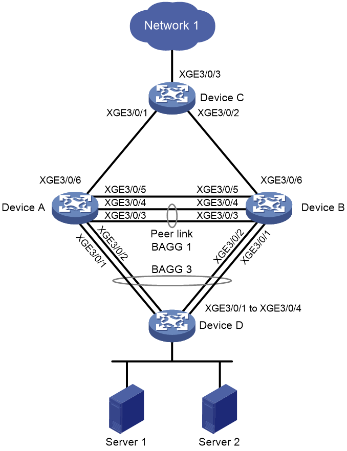
As shown in Figure 3, set up an M-LAG system with Device A and Device B as follows.
· Attach Device D to M-LAG interfaces on the M-LAG system.
· Configure ECMP routes between the M-LAG system and Device C.
· Configure dual-active VLAN interfaces on the M-LAG system to provide IPv4 and IPv6 gateway services for the servers.
|
Interface |
IP address |
Device |
|
|
Device A |
XGE3/0/1 |
- |
Device D: XGE3/0/1 |
|
XGE3/0/2 |
- |
Device D: XGE3/0/2 |
|
|
XGE3/0/3 |
- |
Device B: XGE3/0/3 |
|
|
XGE3/0/4 |
- |
Device B: XGE3/0/4 |
|
|
XGE3/0/5 |
IPv4: 21.1.1.1 IPv6: 21::1 |
Device B: XGE3/0/5 |
|
|
XGE3/0/6 |
- |
Device C: XGE3/0/1 |
|
|
VLAN-interface 100 |
IPv4: 100.1.1.100/24 IPv6: 100::100/64 |
- |
|
|
VLAN-interface 101 |
IPv4: 101.1.1.1/24 IPv6: 101::1/64 |
Device B: VLAN-interface 101 · IPv4: 101.1.1.2/24 · IPv6: 101::2/64 |
|
|
VLAN-interface 32 |
IPv4: 32.1.1.1/24 IPv6: 32::1/64 |
Device C: VLAN-interface 32 · IPv4: 32.1.1.2/24 · IPv6: 32::2/64 |
|
|
Device B |
XGE3/0/1 |
- |
Device D: XGE3/0/3 |
|
XGE3/0/2 |
- |
Device D: XGE3/0/4 |
|
|
XGE3/0/3 |
- |
Device A: XGE3/0/3 |
|
|
XGE3/0/4 |
- |
Device A: XGE3/0/4 |
|
|
XGE3/0/5 |
IPv4: 21.1.1.2 IPv6: 21::2 |
Device A: XGE3/0/5 |
|
|
XGE3/0/6 |
- |
Device C: XGE3/0/6 |
|
|
VLAN-interface 100 |
IPv4: 100.1.1.100/24 IPv6: 100::100/64 |
- |
|
|
VLAN-interface 101 |
IPv4: 101.1.1.2/24 IPv6: 101::2/64 |
Device A: VLAN-interface 101 · IPv4: 101.1.1.1/24 · IPv6: 101::1/64 |
|
|
VLAN-interface 33 |
IPv4: 33.1.1.1/24 IPv6: 33::1/64 |
Device C: VLAN-interface 33 · IPv4: 33.1.1.2/24 · IPv6: 33::2/64 |
|
|
Device C |
XGE3/0/1 |
- |
Device A: XGE3/0/6 |
|
XGE3/0/2 |
- |
Device B: XGE3/0/6 |
|
|
XGE3/0/3 |
- |
Network 1 |
|
|
VLAN-interface 22 |
IPv4: 22.1.1.1/24 IPv6: 22::1/64 |
Network 1 |
|
|
VLAN-interface 32 |
IPv4: 32.1.1.2/24 IPv6: 32::2/64 |
Device A: VLAN-interface 32 · IPv4: 32.1.1.1/24 · IPv6: 32::1/64 |
|
|
VLAN-interface 33 |
IPv4: 33.1.1.2/24 IPv6: 33::2/64 |
Device B: VLAN-interface 33 · IPv4: 33.1.1.1/24 · IPv6: 33::1/64 |
|
|
Device D |
XGE3/0/1 |
- |
Device A: XGE3/0/1 |
|
XGE3/0/2 |
- |
Device A: XGE3/0/2 |
|
|
XGE3/0/3 |
- |
Device B: XGE3/0/1 |
|
|
XGE3/0/4 |
- |
Device B: XGE3/0/2 |
Analysis
To configure IPv4 and IPv6 dual-active VLAN interfaces, perform the following tasks:
· Assign the same IPv4 address, MAC address, IPv6 address, and IPv6 link-local address to VLAN-interface 100 interfaces on Device A and Device B.
· Create VLAN-interface 101 on both Device A and Device B for them to have Layer 3 connectivity. When an uplink to Device C fails, all traffic will be processed by the available M-LAG member device.
Applicable hardware and software versions
The following matrix shows the hardware and software versions to which this configuration example is applicable:
|
Hardware |
Software version |
|
S12500G-AF |
Release 8053P05 and later |
|
S12500CR |
Release 8053P05 and later |
|
S10500X-G |
Release 7753P05 and later |
|
S7500X-G |
Release 7753P05 and later |
Restrictions and guidelines
M-LAG restrictions and guidelines
For two M-LAG member devices to be identified as one M-LAG system, you must configure the same M-LAG system MAC address on them. You must assign unique M-LAG system MAC addresses to M-LAG systems. To configure the M-LAG system MAC address, use the m-lag system-mac command.
Procedures
Configuring Device A
# Configure M-LAG system settings.
<DeviceA> system-view
[DeviceA] m-lag system-mac 0002-0002-0002
[DeviceA] m-lag system-number 1
[DeviceA] m-lag system-priority 123
# Configure M-LAG keepalive packet parameters.
[DeviceA] m-lag keepalive ip destination 21.1.1.2 source 21.1.1.1
# Configure Ten-GigabitEthernet 3/0/5 as a routed (Layer 3) interface and assign the interface IP addresses. The IPv4 address will be used as the source IP address of keepalive packets.
[DeviceA] interface ten-gigabitethernet 3/0/5
[DeviceA-Ten-GigabitEthernet3/0/5] port link-mode route
[DeviceA-Ten-GigabitEthernet3/0/5] ip address 21.1.1.1 255.255.255.0
[DeviceA-Ten-GigabitEthernet3/0/5] ipv6 address 21::1 64
[DeviceA-Ten-GigabitEthernet3/0/5] quit
# Exclude the interface used for M-LAG keepalive detection (Ten-GigabitEthernet 3/0/5) from the shutdown action by M-LAG MAD.
[DeviceA] m-lag mad exclude interface ten-gigabitethernet 3/0/5
# Create Layer 2 dynamic aggregate interface Bridge-Aggregation 1.
[DeviceA] interface bridge-aggregation 1
[DeviceA-Bridge-Aggregation1] link-aggregation mode dynamic
[DeviceA-Bridge-Aggregation1] quit
# Assign Ten-GigabitEthernet 3/0/3 and Ten-GigabitEthernet 3/0/4 to aggregation group 1.
[DeviceA] interface ten-gigabitethernet 3/0/3
[DeviceA-Ten-GigabitEthernet3/0/3] port link-aggregation group 1
[DeviceA-Ten-GigabitEthernet3/0/3] quit
[DeviceA] interface ten-gigabitethernet 3/0/4
[DeviceA-Ten-GigabitEthernet3/0/4] port link-aggregation group 1
[DeviceA-Ten-GigabitEthernet3/0/4] quit
# Specify Bridge-Aggregation 1 as the peer-link interface.
[DeviceA] interface bridge-aggregation 1
[DeviceA-Bridge-Aggregation1] port m-lag peer-link 1
[DeviceA-Bridge-Aggregation1] undo port trunk permit vlan 1
[DeviceA-Bridge-Aggregation1] quit
# Create Layer 2 dynamic aggregate interface Bridge-Aggregation 3, and assign it to M-LAG group 1.
[DeviceA] interface bridge-aggregation 3
[DeviceA-Bridge-Aggregation3] link-aggregation mode dynamic
[DeviceA-Bridge-Aggregation3] port m-lag group 1
[DeviceA-Bridge-Aggregation3] quit
# Assign Ten-GigabitEthernet 3/0/1 and Ten-GigabitEthernet 3/0/2 to aggregation group 3.
[DeviceA] interface ten-gigabitethernet 3/0/1
[DeviceA-Ten-GigabitEthernet3/0/1] port link-aggregation group 3
[DeviceA-Ten-GigabitEthernet3/0/1] quit
[DeviceA] interface ten-gigabitethernet 3/0/2
[DeviceA-Ten-GigabitEthernet3/0/2] port link-aggregation group 3
[DeviceA-Ten-GigabitEthernet3/0/2] quit
# Create VLAN 100 and VLAN 101.
[DeviceA] vlan 100
[DeviceA-vlan100] quit
[DeviceA] vlan 101
[DeviceA-vlan101] quit
# Set the link type of Bridge-Aggregation 3 to trunk, and assign it to VLAN 100.
[DeviceA] interface bridge-aggregation 3
[DeviceA-Bridge-Aggregation3] port link-type trunk
[DeviceA-Bridge-Aggregation3] port trunk permit vlan 100
[DeviceA-Bridge-Aggregation3] undo port trunk permit vlan 1
[DeviceA-Bridge-Aggregation3] quit
# Create VLAN-interface 100, and assign it an IPv4 address and a MAC address for it to act as an IPv4 gateway.
[DeviceA] interface vlan-interface 100
[DeviceA-Vlan-interface100] ip address 100.1.1.100 255.255.255.0
[DeviceA-Vlan-interface100] mac-address 0000-0010-0010
# Assign VLAN-interface 100 an IPv6 address and a link-local address for it to act as an IPv6 gateway.
[DeviceA] interface vlan-interface 100
[DeviceA-Vlan-interface100] ipv6 address 100::100 64
[DeviceA-Vlan-interface100] ipv6 address FE80::80 link-local
# Exclude VLAN-interface 100 from the shutdown action by M-LAG MAD.
[DeviceA] m-lag mad exclude interface vlan-interface100
# Create VLAN-interface 101 and assign it an IPv4 address and an IPv6 address for the device to communicate with the M-LAG peer at Layer 3.
[DeviceA] interface vlan-interface 101
[DeviceA-Vlan-interface101] ip address 101.1.1.1 255.255.255.0
[DeviceA-Vlan-interface101] ipv6 address 101::1 64
[DeviceA-Vlan-interface101] quit
# Exclude VLAN-interface 101 from the shutdown action by M-LAG MAD.
[DeviceA] m-lag mad exclude interface vlan-interface101
# Configure the router ID as 3.3.3.3.
[DeviceA] router id 3.3.3.3
# Configure OSPF on VLAN-interface 100 and VLAN-interface 101. Disable VLAN-interface 100 from receiving and sending OSPF packets. The OSPF configuration enables the M-LAG member devices to have IPv4 connectivity.
[DeviceA] ospf 1
[DeviceA-ospf-1] silent-interface vlan-interface 100
[DeviceA-ospf-1] import-route direct
[DeviceA-ospf-1] area 0
[DeviceA-ospf-1-area-0.0.0.0] quit
[DeviceA-ospf-1] quit
[DeviceA] interface vlan-interface 100
[DeviceA-Vlan-interface100] ospf 1 area 0.0.0.0
[DeviceA-Vlan-interface100] quit
[DeviceA] interface vlan-interface 101
[DeviceA-Vlan-interface101] ospf 1 area 0.0.0.0
[DeviceA-Vlan-interface101] quit
# Configure OSPFv3 on VLAN-interface 100 and VLAN-interface 101. Disable VLAN-interface 100 from receiving and sending OSPFv3 packets. The OSPFv3 configuration enables the M-LAG member devices to have IPv6 connectivity.
[DeviceA] ospfv3 1
[DeviceA-ospfv3-1] silent-interface vlan-interface 100
[DeviceA-ospfv3-1] import-route direct
[DeviceA-ospfv3-1] area 0
[DeviceA-ospfv3-1-area-0.0.0.0] quit
[DeviceA-ospfv3-1] quit
[DeviceA] interface vlan-interface 100
[DeviceA-Vlan-interface100] ospfv3 1 area 0.0.0.0
[DeviceA-Vlan-interface100] quit
[DeviceA] interface vlan-interface 101
[DeviceA-Vlan-interface101] ospfv3 1 area 0.0.0.0
[DeviceA-Vlan-interface101] quit
# Create VLAN 32, and assign Ten-GigabitEthernet 3/0/6 to the VLAN. The interface is an uplink member interface of the M-LAG interface.
[DeviceA] vlan 32
[DeviceA-vlan32] quit
[DeviceA] interface ten-gigabitethernet 3/0/6
[DeviceA-Ten-GigabitEthernet3/0/6] port link-type trunk
[DeviceA-Ten-GigabitEthernet3/0/6] port trunk permit vlan 32
[DeviceA-Ten-GigabitEthernet3/0/6] undo port trunk permit vlan 1
[DeviceA-Ten-GigabitEthernet3/0/6] quit
# Create VLAN-interface 32, and assign the interface an IPv4 address and an IPv6 address. Enable OSPF and OSPFv3 on the interface.
[DeviceA] interface vlan-interface 32
[DeviceA-Vlan-interface32] ip address 32.1.1.1 255.255.255.0
[DeviceA-Vlan-interface32] ipv6 address 32::1 64
[DeviceA-Vlan-interface32] ospf 1 area 0
[DeviceA-Vlan-interface32] ospfv3 1 area 0
[DeviceA-Vlan-interface32] quit
Configuring Device B
# Configure M-LAG system settings.
<DeviceB> system-view
[DeviceB] m-lag system-mac 0002-0002-0002
[DeviceB] m-lag system-number 2
[DeviceB] m-lag system-priority 123
# Configure M-LAG keepalive packet parameters.
[DeviceB] m-lag keepalive ip destination 21.1.1.1 source 21.1.1.2
# Configure Ten-GigabitEthernet 3/0/5 as a routed (Layer 3) interface and assign the interface IP addresses. The IPv4 address will be used as the source IP address of keepalive packets.
[DeviceB] interface ten-gigabitethernet 3/0/5
[DeviceB-Ten-GigabitEthernet3/0/5] port link-mode route
[DeviceB-Ten-GigabitEthernet3/0/5] ip address 21.1.1.2 255.255.255.0
[DeviceB-Ten-GigabitEthernet3/0/5] ipv6 address 21::2 64
[DeviceB-Ten-GigabitEthernet3/0/5] quit
# Exclude the interface used for M-LAG keepalive detection (Ten-GigabitEthernet 3/0/5) from the shutdown action by M-LAG MAD.
[DeviceB] m-lag mad exclude interface ten-gigabitethernet 3/0/5
# Create Layer 2 dynamic aggregate interface Bridge-Aggregation 1.
[DeviceB] interface bridge-aggregation 1
[DeviceB-Bridge-Aggregation1] link-aggregation mode dynamic
[DeviceB-Bridge-Aggregation1] quit
# Assign Ten-GigabitEthernet 3/0/3 and Ten-GigabitEthernet 3/0/4 to aggregation group 1.
[DeviceB] interface ten-gigabitethernet 3/0/3
[DeviceB-Ten-GigabitEthernet3/0/3] port link-aggregation group 1
[DeviceB-Ten-GigabitEthernet3/0/3] quit
[DeviceB] interface ten-gigabitethernet 3/0/4
[DeviceB-Ten-GigabitEthernet3/0/4] port link-aggregation group 1
[DeviceB-Ten-GigabitEthernet3/0/4] quit
# Specify Bridge-Aggregation 1 as the peer-link interface.
[DeviceB] interface bridge-aggregation 1
[DeviceB-Bridge-Aggregation1] port m-lag peer-link 1
[DeviceB-Bridge-Aggregation1] undo port trunk permit vlan 1
[DeviceB-Bridge-Aggregation1] quit
# Create Layer 2 dynamic aggregate interface Bridge-Aggregation 3, and assign it to M-LAG group 1.
[DeviceB] interface bridge-aggregation 3
[DeviceB-Bridge-Aggregation3] link-aggregation mode dynamic
[DeviceB-Bridge-Aggregation3] port m-lag group 1
[DeviceB-Bridge-Aggregation3] quit
# Assign Ten-GigabitEthernet 3/0/1 and Ten-GigabitEthernet 3/0/2 to aggregation group 3.
[DeviceB] interface ten-gigabitethernet 3/0/1
[DeviceB-Ten-GigabitEthernet3/0/1] port link-aggregation group 3
[DeviceB-Ten-GigabitEthernet3/0/1] quit
[DeviceB] interface ten-gigabitethernet 3/0/2
[DeviceB-Ten-GigabitEthernet3/0/2] port link-aggregation group 3
[DeviceB-Ten-GigabitEthernet3/0/2] quit
# Create VLAN 100 and VLAN 101.
[DeviceB] vlan 100
[DeviceB-vlan100] quit
[DeviceB] vlan 101
[DeviceB-vlan101] quit
# Set the link type of Bridge-Aggregation 3 to trunk, and assign it to VLAN 100.
[DeviceB] interface bridge-aggregation 3
[DeviceB-Bridge-Aggregation3] port link-type trunk
[DeviceB-Bridge-Aggregation3] port trunk permit vlan 100
[DeviceB-Bridge-Aggregation3] undo port trunk permit vlan 1
[DeviceB-Bridge-Aggregation3] quit
# Create VLAN-interface 100, and assign it an IPv4 address and a MAC address for it to act as an IPv4 gateway.
[DeviceB] interface vlan-interface 100
[DeviceB-Vlan-interface100] ip address 100.1.1.100 255.255.255.0
[DeviceB-Vlan-interface100] mac-address 0000-0010-0010
# Assign VLAN-interface 100 an IPv6 address and a link-local address for it to act as an IPv6 gateway.
[DeviceB] interface vlan-interface 100
[DeviceB-Vlan-interface100] ipv6 address 100::100 64
[DeviceB-Vlan-interface100] ipv6 address FE80::80 link-local
# Exclude VLAN-interface 100 from the shutdown action by M-LAG MAD.
[DeviceB] m-lag mad exclude interface vlan-interface100
# Create VLAN-interface 101 and assign it an IPv4 address and an IPv6 address for the device to communicate with the M-LAG peer at Layer 3.
[DeviceB] interface vlan-interface 101
[DeviceB-vlan-interface101] ip address 101.1.1.2 24
[DeviceB-vlan-interface101] ipv6 address 101::2 64
[DeviceB-vlan-interface101] quit
# Exclude VLAN-interface 101 from the shutdown action by M-LAG MAD.
[DeviceB] m-lag mad exclude interface vlan-interface101
# Configure the router ID as 4.4.4.4.
[DeviceB] router id 4.4.4.4
# Configure OSPF on VLAN-interface 100 and VLAN-interface 101. Disable VLAN-interface 100 from receiving and sending OSPF packets. The OSPF configuration enables the M-LAG member devices to have IPv4 connectivity.
[DeviceB] ospf 1
[DeviceB-ospf-1] silent-interface vlan-interface100
[DeviceB-ospf-1] import-route direct
[DeviceB-ospf-1] area 0
[DeviceB-ospf-1-area-0.0.0.0] quit
[DeviceB-ospf-1] quit
[DeviceB] interface vlan-interface 100
[DeviceB-Vlan-interface100] ospf 1 area 0.0.0.0
[DeviceB-Vlan-interface100] quit
[DeviceB] interface vlan-interface 101
[DeviceB-Vlan-interface101] ospf 1 area 0.0.0.0
[DeviceB-Vlan-interface101] quit
# Configure OSPFv3 on VLAN-interface 100 and VLAN-interface 101. Disable VLAN-interface 100 from receiving and sending OSPFv3 packets. The OSPFv3 configuration enables the M-LAG member devices to have IPv6 connectivity.
[DeviceB] ospfv3 1
[DeviceB-ospf-1] silent-interface vlan-interface100
[DeviceB-ospfv3-1] import-route direct
[DeviceB-ospfv3-1] area 0
[DeviceB-ospfv3-1-area-0.0.0.0] quit
[DeviceB-ospfv3-1] quit
[DeviceB] interface vlan-interface 100
[DeviceB-vlan-interface100] ospfv3 1 area 0
[DeviceB-vlan-interface100] quit
[DeviceB] interface vlan-interface 101
[DeviceB-vlan-interface101] ospfv3 1 area 0
[DeviceB-vlan-interface101] quit
# Create VLAN 33, and assign Ten-GigabitEthernet 3/0/6 to the VLAN. The interface is an uplink member interface of the M-LAG interface.
[DeviceB] vlan 33
[DeviceB-vlan33] quit
[DeviceB] interface ten-gigabitethernet 3/0/6
[DeviceB-Ten-GigabitEthernet3/0/6] port link-type trunk
[DeviceB-Ten-GigabitEthernet3/0/6] port trunk permit vlan 33
[DeviceB-Ten-GigabitEthernet3/0/6] undo port trunk permit vlan 1
[DeviceB-Ten-GigabitEthernet3/0/6] quit
# Create VLAN-interface 33, and assign the interface an IPv4 address and an IPv6 address. Enable OSPF and OSPFv3 on the interface.
[DeviceB] interface vlan-interface 33
[DeviceB-Vlan-interface33] ip address 33.1.1.1 255.255.255.0
[DeviceB-Vlan-interface33] ipv6 address 33::1 64
[DeviceB-Vlan-interface33] ospf 1 area 0
[DeviceB-Vlan-interface33] ospfv3 1 area 0
[DeviceB-Vlan-interface33] quit
Configuring Device C
# Create VLAN 32 and assign Ten-GigabitEthernet 3/0/1 (attached to Device A) to the VLAN. Create VLAN-interface 32 and assign it an IPv4 address and an IPv6 address.
<DeviceC> system-view
[DeviceC] vlan 32
[DeviceC-vlan32] quit
[DeviceC] interface ten-gigabitethernet 3/0/1
[DeviceC-Ten-GigabitEthernet3/0/1] port link-type trunk
[DeviceC-Ten-GigabitEthernet3/0/1] port trunk permit vlan 32
[DeviceC-Ten-GigabitEthernet3/0/1] undo port trunk permit vlan 1
[DeviceC-Ten-GigabitEthernet3/0/] quit
[DeviceC] interface vlan-interface 32
[DeviceC-Vlan-interface32] ip address 32.1.1.2 24
[DeviceC-Vlan-interface32] ipv6 address 32::2 64
[DeviceC-Vlan-interface32] quit
# Create VLAN 33 and assign Ten-GigabitEthernet 3/0/2 (attached to Device B) to the VLAN. Create VLAN-interface 33 and assign it an IPv4 address and an IPv6 address.
[DeviceC] vlan 33
[DeviceC-vlan33] quit
[DeviceC] interface ten-gigabitethernet 3/0/2
[DeviceC-Ten-GigabitEthernet3/0/2] port link-type trunk
[DeviceC-Ten-GigabitEthernet3/0/2] port trunk permit vlan 33
[DeviceC-Ten-GigabitEthernet3/0/2] undo port trunk permit vlan 1
[DeviceC-Ten-GigabitEthernet3/0/2] quit
[DeviceC] interface vlan-interface 33
[DeviceC-Vlan-interface33] ip address 33.1.1.2 24
[DeviceC-Vlan-interface33] ipv6 address 33::2 64
[DeviceC-Vlan-interface33] quit
# Configure the router ID as 5.5.5.5.
[DeviceC] router id 5.5.5.5
# Enable OSPF on VLAN-interface 32 and VLAN-interface 33.
[DeviceC] ospf 1
[DeviceC-ospf-1] import-route direct
[DeviceC-ospf-1] area 0
[DeviceC-ospf-1-area-0.0.0.0] quit
[DeviceC-ospf-1] quit
[DeviceC] interface vlan-interface 32
[DeviceC-Vlan-interface32] ospf 1 area 0
[DeviceC-Vlan-interface32] quit
[DeviceC] interface vlan-interface 33
[DeviceC-Vlan-interface33] ospf 1 area 0
[DeviceC-Vlan-interface33] quit
# Enable OSPFv3 on VLAN-interface 32 and VLAN-interface 33.
[DeviceC] ospfv3 1
[DeviceC-ospfv3-1] import-route direct
[DeviceC-ospfv3-1] area 0
[DeviceC-ospfv3-1-area-0.0.0.0] quit
[DeviceC-ospfv3-1] quit
[DeviceC] interface vlan-interface 32
[DeviceC-Vlan-interface32] ospfv3 1 area 0
[DeviceC-Vlan-interface32] quit
[DeviceC] interface vlan-interface 33
[DeviceC-Vlan-interface33] ospfv3 1 area 0
[DeviceC-Vlan-interface33] quit
# Create VLAN 22, and assign Ten-GigabitEthernet 3/0/3 (attached to the upstream network) to the VLAN. Create VLAN-interface 22 and assign it an IPv4 address and an IPv6 address.
[DeviceC] vlan 22
[DeviceC-vlan22] quit
[DeviceC] interface ten-gigabitethernet 3/0/3
[DeviceC-Ten-GigabitEthernet3/0/3] port link-type trunk
[DeviceC-Ten-GigabitEthernet3/0/3] port trunk permit vlan 22
[DeviceC-Ten-GigabitEthernet3/0/3] undo port trunk permit vlan 1
[DeviceC-Ten-GigabitEthernet3/0/3] quit
[DeviceC] interface vlan-interface 22
[DeviceC-Vlan-interface22] ip address 22.1.1.1 24
[DeviceC-Vlan-interface22] ipv6 address 22::1 64
[DeviceC-Vlan-interface22] quit
Configuring Device D
# Create Layer 2 dynamic aggregate interface Bridge-Aggregation 3.
<DeviceD> system-view
[DeviceD] interface bridge-aggregation 3
[DeviceD-Bridge-Aggregation3] link-aggregation mode dynamic
[DeviceD-Bridge-Aggregation3] quit
# Assign Ten-GigabitEthernet 3/0/1 through Ten-GigabitEthernet 3/0/4 to aggregation group 3.
[DeviceD] interface range ten-gigabitethernet 3/0/1 to ten-gigabitethernet 3/0/4
[DeviceD-if-range] port link-aggregation group 3
[DeviceD-if-range] quit
# Create VLAN 100.
[DeviceD] vlan 100
[DeviceD-vlan100] quit
# Set the link type of Bridge-Aggregation 3 to trunk, and assign it to VLAN 100.
[DeviceD] interface bridge-aggregation 3
[DeviceD-Bridge-Aggregation3] port link-type trunk
[DeviceD-Bridge-Aggregation3] port trunk permit vlan 100
[DeviceD-Bridge-Aggregation3] undo port trunk permit vlan 1
[DeviceD-Bridge-Aggregation3] quit
Verifying the configuration
Verifying the M-LAG configuration
The following tasks use Device A as an example.
# Verify that Device A has formed an M-LAG system with Device B.
[DeviceA] display m-lag summary
Flags: A -- Aggregate interface down, B -- No peer M-LAG interface configured
C -- Configuration consistency check failed
Peer-link interface: BAGG1
Peer-link interface state (cause): UP
Keepalive link state (cause): UP
M-LAG interface information
M-LAG IF M-LAG group Local state (cause) Peer state Remaining down time (s)
BAGG3 1 UP UP -
# Verify that the keepalive link is operating correctly.
[DeviceA] display m-lag keepalive
Neighbor keepalive link status: Up
Neighbor is alive for: 64765 s 28 ms
Keepalive packet transmission status:
Sent: Successful
Received: Successful
Last received keepalive packet information:
Source IP address: 21.1.1.2
Time: 2021/01/17 17:10:52
Action: Accept
M-LAG keepalive parameters:
Destination IP address: 21.1.1.2
Source IP address: 21.1.1.1
Keepalive UDP port : 6400
Keepalive VPN name : N/A
Keepalive interval : 1000 ms
Keepalive timeout : 5 sec
Keepalive hold time: 3 sec
# Verify that the M-LAG system is operating correctly.
[DeviceA] display m-lag system
System information
Local system number: 1 Peer system number: 2
Local system MAC: 0002-0002-0002 Peer system MAC: 0002-0002-0002
Local system priority: 123 Peer system priority: 123
Local bridge MAC: 3cd4-3ce1-0200 Peer bridge MAC: 3cd4-437d-0300
Local effective role: Primary Peer effective role: Secondary
Health level: 0
Standalone mode on split: Disabled
In standalone mode: No
System timer information
Timer State Value (s) Remaining time (s)
Auto recovery Disabled - -
Restore delay Disabled 30 -
Consistency-check delay Disabled 15 -
Standalone delay Disabled - -
Role to None delay Disabled 60 -
# Verify that the interfaces used by M-LAG are operating correctly.
[DeviceA] display m-lag verbose
Flags: A -- Home_Gateway, B -- Neighbor_Gateway, C -- Other_Gateway,
D -- PeerLink_Activity, E -- DRCP_Timeout, F -- Gateway_Sync,
G -- Port_Sync, H -- Expired
Peer-link interface/Peer-link interface ID: BAGG1/1
State: UP
Cause: -
Local DRCP flags/Peer DRCP flags: ABDFG/ABDFG
Local Selected ports (index): XGE3/0/3 (27), XGE3/0/4 (32)
Peer Selected ports indexes: 125, 130
M-LAG interface/M-LAG group ID: BAGG3/1
Local M-LAG interface state: UP
Peer M-LAG interface state: UP
M-LAG group state: UP
Local M-LAG interface down cause: -
Remaining M-LAG DOWN time: -
Local M-LAG interface LACP MAC: Config=N/A, Effective=0002-0002-0002
Peer M-LAG interface LACP MAC: Config=N/A, Effective=0002-0002-0002
Local M-LAG interface LACP priority: Config=32768, Effective=123
Peer M-LAG interface LACP priority: Config=32768, Effective=123
Local DRCP flags/Peer DRCP flags: ABDFG/ABDFG
Local Selected ports (index): XGE3/0/1 (12), XGE3/0/2 (13)
Peer Selected ports indexes: 56, 57
Verifying routing configuration
# Verify that Device A have established OSPF neighbor relationships.
[DeviceA] display ospf peer
OSPF Process 1 with Router ID 3.3.3.3
Neighbor Brief Information
Area: 0.0.0.0
Router ID Address Pri Dead-Time State Interface
4.4.4.4 101.1.1.2 1 36 Full/DR Vlan101
5.5.5.5 32.1.1.2 1 38 Full/DR Vlan32
# Verify that Device A have established OSPFv3 neighbor relationships.
[DeviceA] display ospfv3 peer
OSPFv3 Process 1 with Router ID 3.3.3.3
Area: 0.0.0.0
-------------------------------------------------------------------------
Router ID Pri State Dead-Time InstID Interface
4.4.4.4 1 Full/DR 00:00:36 0 Vlan101
5.5.5.5 1 Full/DR 00:00:35 0 Vlan32
# Verify that Device B have established OSPF neighbor relationships.
[DeviceB] display ospf peer
OSPF Process 1 with Router ID 4.4.4.4
Neighbor Brief Information
Area: 0.0.0.0
Router ID Address Pri Dead-Time State Interface
3.3.3.3 101.1.1.1 1 32 Full/BDR Vlan101
5.5.5.5 33.1.1.2 1 33 Full/DR Vlan33
# Verify that Device B have established OSPFv3 neighbor relationships.
[DeviceB] display ospfv3 peer
OSPFv3 Process 1 with Router ID 4.4.4.4
Area: 0.0.0.0
-------------------------------------------------------------------------
Router ID Pri State Dead-Time InstID Interface
3.3.3.3 1 Full/BDR 00:00:35 0 Vlan101
5.5.5.5 1 Full/DR 00:00:38 0 Vlan33
# Verify that Device C have established OSPF neighbor relationships.
[DeviceC] display ospf peer
OSPF Process 1 with Router ID 5.5.5.5
Neighbor Brief Information
Area: 0.0.0.0
Router ID Address Pri Dead-Time State Interface
3.3.3.3 32.1.1.1 1 32 Full/DR Vlan32
4.4.4.4 33.1.1.1 1 38 Full/DR Vlan33
# Verify that Device C have established OSPFv3 neighbor relationships.
[DeviceC] display ospfv3 peer
OSPFv3 Process 1 with Router ID 5.5.5.5
Area: 0.0.0.0
-------------------------------------------------------------------------
Router ID Pri State Dead-Time InstID Interface
3.3.3.3 1 Full/DR 00:00:37 0 Vlan32
4.4.4.4 1 Full/DR 00:00:34 0 Vlan33
Verifying network connectivity
Verify that Server 1 and Server 2 have both IPv4 and IPv6 connectivity to the upstream network connected to Device C.
Verifying traffic failover
Disconnect the uplink interface on Device A and verify that Server 1 and Server 2 have connectivity to the upstream network connected to Device C. Transient traffic loss will occur during traffic failover.
Configuration files
· Device A:
#
router id 3.3.3.3
#
ospf 1
import-route direct
silent-interface Vlan-interface100
area 0.0.0.0
#
ospfv3 1
import-route direct
silent-interface Vlan-interface100
area 0.0.0.0
#
vlan 1
#
vlan 32
#
vlan 100 to 101
#
interface Bridge-Aggregation1
port link-type trunk
undo port trunk permit vlan 1
port trunk permit vlan 2 to 4094
link-aggregation mode dynamic
port m-lag peer-link 1
#
interface Bridge-Aggregation3
port link-type trunk
undo port trunk permit vlan 1
port trunk permit vlan 100
link-aggregation mode dynamic
port m-lag group 1
#
interface Vlan-interface32
ip address 32.1.1.1 255.255.255.0
ospf 1 area 0.0.0.0
ospfv3 1 area 0.0.0.0
ipv6 address 32::1/64
#
interface Vlan-interface100
ip address 100.1.1.100 255.255.255.0
ospf 1 area 0.0.0.0
ospfv3 1 area 0.0.0.0
mac-address 0000-0010-0010
ipv6 address FE80::80 link-local
ipv6 address 100::100/64
#
interface Vlan-interface101
ip address 101.1.1.1 255.255.255.0
ospf 1 area 0.0.0.0
ospfv3 1 area 0.0.0.0
ipv6 address 101::1/64
#
interface Ten-GigabitEthernet3/0/1
port link-mode bridge
port link-type trunk
undo port trunk permit vlan 1
port trunk permit vlan 100
combo enable fiber
port link-aggregation group 3
#
interface Ten-GigabitEthernet3/0/2
port link-mode bridge
port link-type trunk
undo port trunk permit vlan 1
port trunk permit vlan 100
combo enable fiber
port link-aggregation group 3
#
interface Ten-GigabitEthernet3/0/3
port link-mode bridge
port link-type trunk
undo port trunk permit vlan 1
port trunk permit vlan 2 to 4094
port link-aggregation group 1
#
interface Ten-GigabitEthernet3/0/4
port link-mode bridge
port link-type trunk
undo port trunk permit vlan 1
port trunk permit vlan 2 to 4094
port link-aggregation group 1
#
interface Ten-GigabitEthernet3/0/5
port link-mode route
ip address 21.1.1.1 255.255.255.0
ipv6 address 21::1/64
#
interface Ten-GigabitEthernet3/0/6
port link-mode bridge
port link-type trunk
undo port trunk permit vlan 1
port trunk permit vlan 32
#
m-lag system-mac 0002-0002-0002
m-lag system-number 1
m-lag system-priority 123
m-lag keepalive ip destination 21.1.1.2 source 21.1.1.1
m-lag mad exclude interface Ten-GigabitEthernet2/0/19
m-lag mad exclude interface Vlan-interface100
m-lag mad exclude interface Vlan-interface101
#
· Device B:
#
router id 4.4.4.4
#
ospf 1
import-route direct
silent-interface Vlan-interface100
area 0.0.0.0
#
ospfv3 1
import-route direct
silent-interface Vlan-interface100
area 0.0.0.0
#
vlan 1
#
vlan 33
#
vlan 100 to 101
#
interface Bridge-Aggregation1
port link-type trunk
port trunk permit vlan all
link-aggregation mode dynamic
port m-lag peer-link 1
#
interface Bridge-Aggregation3
port link-type trunk
undo port trunk permit vlan 1
port trunk permit vlan 100
link-aggregation mode dynamic
port m-lag group 1
#
interface Vlan-interface33
ip address 33.1.1.1 255.255.255.0
ospf 1 area 0.0.0.0
ospfv3 1 area 0.0.0.0
ipv6 address 33::1/64
#
interface Vlan-interface100
ip address 100.1.1.100 255.255.255.0
ospf 1 area 0.0.0.0
ospfv3 1 area 0.0.0.0
mac-address 0000-0010-0010
ipv6 address FE80::80 link-local
ipv6 address 100::100/64
#
interface Vlan-interface101
ip address 101.1.1.2 255.255.255.0
ospf 1 area 0.0.0.0
ospfv3 1 area 0.0.0.0
ipv6 address 101::2/64
#
interface Ten-GigabitEthernet3/0/1
port link-mode bridge
port link-type trunk
undo port trunk permit vlan 1
port trunk permit vlan 100
combo enable fiber
port link-aggregation group 3
#
interface Ten-GigabitEthernet3/0/2
port link-mode bridge
port link-type trunk
undo port trunk permit vlan 1
port trunk permit vlan 100
combo enable fiber
port link-aggregation group 3
#
interface Ten-GigabitEthernet3/0/3
port link-mode bridge
port link-type trunk
port trunk permit vlan all
port link-aggregation group 1
#
interface Ten-GigabitEthernet3/0/4
port link-mode bridge
port link-type trunk
port trunk permit vlan all
port link-aggregation group 1
#
interface Ten-GigabitEthernet3/0/5
port link-mode route
ip address 21.1.1.2 255.255.255.0
ipv6 address 21::2/64
#
interface Ten-GigabitEthernet3/0/6
port link-mode bridge
port link-type trunk
undo port trunk permit vlan 1
port trunk permit vlan 33
#
m-lag system-mac 0002-0002-0002
m-lag system-number 2
m-lag system-priority 123
m-lag keepalive ip destination 21.1.1.1 source 21.1.1.2
m-lag mad exclude interface Ten-GigabitEthernet2/0/19
m-lag mad exclude interface Vlan-interface100
m-lag mad exclude interface Vlan-interface101
#
· Device C:
#
router id 5.5.5.5
#
ospf 1
import-route direct
area 0.0.0.0
#
ospfv3 1
import-route direct
area 0.0.0.0
#
vlan 1
#
vlan 22
#
vlan 32 to 33
#
interface Vlan-interface22
ip address 22.1.1.1 255.255.255.0
ipv6 address 22::1/64
#
interface Vlan-interface32
ip address 32.1.1.1 255.255.255.0
ospf 1 area 0.0.0.0
ospfv3 1 area 0.0.0.0
ipv6 address 32::2/64
#
interface Vlan-interface33
ip address 33.1.1.2 255.255.255.0
ospf 1 area 0.0.0.0
ospfv3 1 area 0.0.0.0
ipv6 address 33::2/64
#
interface Ten-GigabitEthernet3/0/1
port link-mode bridge
port link-type trunk
undo port trunk permit vlan 1
port trunk permit vlan 32
#
interface Ten-GigabitEthernet3/0/2
port link-mode bridge
port link-type trunk
undo port trunk permit vlan 1
port trunk permit vlan 33
#
interface Ten-GigabitEthernet3/0/3
port link-mode bridge
port link-type trunk
undo port trunk permit vlan 1
port trunk permit vlan 22
#
· Device D:
#
vlan 1
#
vlan 100
#
interface Bridge-Aggregation3
port link-type trunk
undo port trunk permit vlan 1
port trunk permit vlan 100
link-aggregation mode dynamic
#
interface Ten-GigabitEthernet3/0/1
port link-mode bridge
port link-type trunk
undo port trunk permit vlan 1
port trunk permit vlan 100
port link-aggregation group 3
#
interface Ten-GigabitEthernet3/0/2
port link-mode bridge
port link-type trunk
undo port trunk permit vlan 1
port trunk permit vlan 100
port link-aggregation group 3
#
interface Ten-GigabitEthernet3/0/3
port link-mode bridge
port link-type trunk
undo port trunk permit vlan 1
port trunk permit vlan 100
port link-aggregation group 3
#
interface Ten-GigabitEthernet3/0/4
port link-mode bridge
port link-type trunk
undo port trunk permit vlan 1
port trunk permit vlan 100
port link-aggregation group 3
#