- Table of Contents
-
- 03-Layer 2—LAN Switching Configuration Examples
- 01-Ethernet Link Aggregation Configuration Examples
- 02-M-LAG Configuration Examples
- 03-MAC Address Table Configuration Examples
- 04-MVRP Configuration Examples
- 05-Port Isolation Configuration Examples
- 06-S-MLAG Configuration Examples
- 07-Spanning Tree Configuration Examples
- 08-VLAN Configuration Examples
- 09-VLAN Tagging Configuration Examples
- Related Documents
-
| Title | Size | Download |
|---|---|---|
| 04-MVRP Configuration Examples | 109.10 KB |
Applicable hardware and software versions
Verifying local VLAN information on all devices
Verifying VLAN information after changing the registration mode
Verifying VLAN information after changing the network topology
Introduction
This document provides MVRP configuration examples.
Prerequisites
The configuration examples in this document were created and verified in a lab environment, and all the devices were started with the factory default configuration. When you are working on a live network, make sure you understand the potential impact of every command on your network.
This document assumes that you have basic knowledge of MVRP.
Example: Configuring MVRP
Network configuration
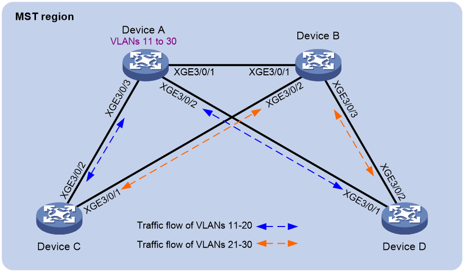
As shown in Figure 1:
· Device A and Device B are core layer devices. Device C and Device D are aggregation layer devices.
· Ports on all devices allow packets from VLANs 11 through 30 to pass through.
· MSTP implements load balancing and link backup for traffic of VLANs 11 through 30 between the core layer devices and the aggregation layer devices.
Configure MVRP on all devices to synchronize and update VLAN information. When the network is stable, set the registration mode to fixed on Ten-GigabitEthernet 3/0/1 of Device B to maintain dynamic VLAN information.
Analysis
To meet the network requirements, you must perform the following tasks:
· To assign all devices to the same MST region, configure the same settings for the following parameters on all the devices:
¡ Spanning tree mode. (This example uses the default mode MSTP.)
¡ MST region name. (This example uses the region name test.)
¡ MST region revision level. (This example uses the default setting 0.)
¡ VLAN-to-instance mappings. (This example maps VLANs 11 through 20 to MSTI 1, and maps VLANs 21 through 30 to MSTI 2.)
· For MSTIs 1 and 2 to use different uplinks for backup, set Device A and Device B as the root bridges of MSTIs 1 and 2, respectively.
· Make sure each MSTI is mapped to an existing VLAN on each device in the network.
Applicable hardware and software versions
The following matrix shows the hardware and software versions to which this configuration example is applicable:
|
Hardware |
Software version |
|
S12500G-AF |
Release 8053P05 and later |
|
S12500CR |
Release 8053P05 and later |
|
S10500X-G |
Release 7753P05 and later |
|
S7500X-G |
Release 7753P05 and later |
Restrictions and guidelines
When you configure MVRP, follow these restrictions and guidelines:
· MVRP can work with STP, RSTP, or MSTP. Ports blocked by STP, RSTP, or MSTP can receive and send MVRP frames. MVRP cannot work with other link layer topology protocols, including service loopback, PVST, RRPP, and Smart Link.
· On a Layer 2 aggregate interface, MVRP takes effect on both the aggregate interface and all Selected member ports in the link aggregation group.
· MVRP configuration made on an aggregation group member port takes effect only after the port is removed from the aggregation group.
Procedures
Configuring Device A
# Create VLANs 11 through 30.
<DeviceA> system-view
[DeviceA] vlan 11 to 30
# Enter MST region view.
[DeviceA] stp region-configuration
# Set the MST region name to test.
[DeviceA-mst-region] region-name test
# Map VLANs 11 through 20 to MSTI 1.
[DeviceA-mst-region] instance 1 vlan 11 to 20
# Map VLANs 21 through 30 to MSTI 2.
[DeviceA-mst-region] instance 2 vlan 21 to 30
# Activate the MST region configuration.
[DeviceA-mst-region] active region-configuration
[DeviceA-mst-region] quit
# Configure Device A as the root bridge of MSTI 1.
[DeviceA] stp instance 1 root primary
# Enable the spanning tree feature globally.
[DeviceA] stp global enable
# Configure the ports Ten-GigabitEthernet 3/0/1 through Ten-GigabitEthernet 3/0/3 as trunk ports, assign the ports to VLANs 11 through 30, and enable MVRP on these ports.
[DeviceA] interface range ten-gigabitethernet 3/0/1 to ten-gigabitethernet 3/0/3
[DeviceA-if-range] port link-type trunk
[DeviceA-if-range] port trunk permit vlan 11 to 30
[DeviceA-if-range] mvrp enable
[DeviceA-if-range] quit
Configuring Device B
# Create VLANs 11 and 21.
<DeviceB> system-view
[DeviceB] vlan 11
[DeviceB-vlan11] quit
[DeviceB] vlan 21
[DeviceB-vlan21] quit
# Enter MST region view.
[DeviceB] stp region-configuration
# Set the MST region name to test.
[DeviceB-mst-region] region-name test
# Map VLANs 11 through 20 to MSTI 1.
[DeviceB-mst-region] instance 1 vlan 11 to 20
# Map VLANs 21 through 30 to MSTI 2.
[DeviceB-mst-region] instance 2 vlan 21 to 30
# Activate the MST region configuration.
[DeviceB-mst-region] active region-configuration
[DeviceB-mst-region] quit
# Configure Device B as the root bridge of MSTI 2.
[DeviceB] stp instance 2 root primary
# Enable the spanning tree feature globally.
[DeviceB] stp global enable
# Enable MVRP globally.
[DeviceB] mvrp global enable
# Configure the ports Ten-GigabitEthernet 3/0/1 through Ten-GigabitEthernet 3/0/3 as trunk ports, assign the ports to VLANs 11 through 30, and enable MVRP on these ports.
[DeviceB] interface range ten-gigabitethernet 3/0/1 to ten-gigabitethernet 3/0/3
[DeviceB-if-range] port link-type trunk
[DeviceB-if-range] port trunk permit vlan 11 to 30
[DeviceB-if-range] mvrp enable
[DeviceB-if-range] quit
Configuring Device C
# Create VLANs 11 and 21.
<DeviceC> system-view
[DeviceC] vlan 11
[DeviceC-vlan11] quit
[DeviceC] vlan 21
[DeviceC-vlan21] quit
# Enter MST region view.
[DeviceC] stp region-configuration
# Set the MST region name to test.
[DeviceC-mst-region] region-name test
# Map VLANs 11 through 20 to MSTI 1.
[DeviceC-mst-region] instance 1 vlan 11 to 20
# Map VLANs 21 through 30 to MSTI 2.
[DeviceC-mst-region] instance 2 vlan 21 to 30
# Activate the MST region configuration.
[DeviceC-mst-region] active region-configuration
[DeviceC-mst-region] quit
# Enable the spanning tree feature globally.
[DeviceC] stp global enable
# Enable MVRP globally.
[DeviceC] mvrp global enable
# Configure the ports Ten-GigabitEthernet 3/0/1 and Ten-GigabitEthernet 3/0/2 as trunk ports, assign the ports to VLANs 11 through 30, and enable MVRP on these ports.
[DeviceC] interface range ten-gigabitethernet 3/0/1 to ten-gigabitethernet 3/0/2
[DeviceC-if-range] port link-type trunk
[DeviceC-if-range] port trunk permit vlan 11 to 30
[DeviceC-if-range] mvrp enable
[DeviceC-if-range] quit
Configuring Device D
Configure Device D in the same way Device C is configured. (Details not shown.)
Verifying the configuration
Verifying MSTI topologies
# Display brief spanning tree information on Device A.
[DeviceA] display stp brief
MST ID Port Role STP State Protection
...
1 Ten-GigabitEthernet3/0/1 DESI FORWARDING NONE
1 Ten-GigabitEthernet3/0/2 DESI FORWARDING NONE
1 Ten-GigabitEthernet3/0/3 DESI FORWARDING NONE
2 Ten-GigabitEthernet3/0/1 ROOT FORWARDING NONE
2 Ten-GigabitEthernet3/0/2 DESI FORWARDING NONE
2 Ten-GigabitEthernet3/0/3 DESI FORWARDING NONE
# Display brief spanning tree information on Device B.
[DeviceB] display stp brief
MST ID Port Role STP State Protection
...
1 Ten-GigabitEthernet3/0/1 ROOT FORWARDING NONE
1 Ten-GigabitEthernet3/0/2 DESI FORWARDING NONE
1 Ten-GigabitEthernet3/0/3 DESI FORWARDING NONE
2 Ten-GigabitEthernet3/0/1 DESI FORWARDING NONE
2 Ten-GigabitEthernet3/0/2 DESI FORWARDING NONE
2 Ten-GigabitEthernet3/0/3 DESI FORWARDING NONE
# Display brief spanning tree information on Device C.
[DeviceC] display stp brief
MST ID Port Role STP State Protection
...
1 Ten-GigabitEthernet3/0/1 ALTE DISCARDING NONE
1 Ten-GigabitEthernet3/0/2 ROOT FORWARDING NONE
2 Ten-GigabitEthernet3/0/1 ROOT FORWARDING NONE
2 Ten-GigabitEthernet3/0/2 ALTE DISCARDING NONE
# Display brief spanning tree information on Device D.
[DeviceD] display stp brief
MST ID Port Role STP State Protection
...
1 Ten-GigabitEthernet3/0/1 ROOT FORWARDING NONE
1 Ten-GigabitEthernet3/0/2 ALTE DISCARDING NONE
2 Ten-GigabitEthernet3/0/1 ALTE DISCARDING NONE
2 Ten-GigabitEthernet3/0/2 ROOT FORWARDING NONE
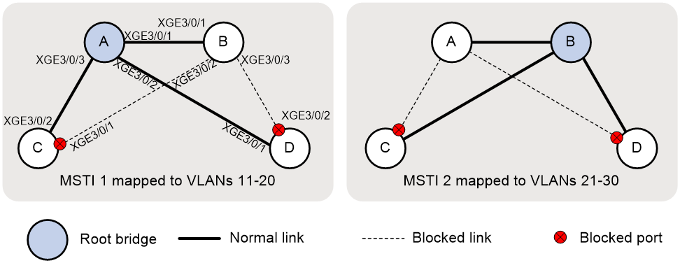
Based on the output, you can get MSTI topologies, as shown in Figure 2.
Verifying local VLAN information on all devices
# Display local VLAN information on Device A.
[DeviceA] display mvrp running-status
-------[MVRP Global Info] -------
Global Status : Enabled
Compliance-GVRP : False
----[Ten-GigabitEthernet3/0/1] ----
Config Status : Enabled
Running Status : Enabled
Join Timer : 20 (centiseconds)
Leave Timer : 60 (centiseconds)
Periodic Timer : 100 (centiseconds)
LeaveAll Timer : 1000 (centiseconds)
Registration Type : Normal
Registered VLANs :
1(default), 11, 21
Declared VLANs :
1(default), 11-30
Propagated VLANs :
1(default), 11, 21
----[Ten-GigabitEthernet3/0/2] ----
Config Status : Enabled
Running Status : Enabled
Join Timer : 20 (centiseconds)
Leave Timer : 60 (centiseconds)
Periodic Timer : 100 (centiseconds)
LeaveAll Timer : 1000 (centiseconds)
Registration Type : Normal
Registered VLANs :
1(default), 11
Declared VLANs :
1(default), 11-30
Propagated VLANs :
1(default), 11
----[Ten-GigabitEthernet3/0/3] ----
Config Status : Enabled
Running Status : Enabled
Join Timer : 20 (centiseconds)
Leave Timer : 60 (centiseconds)
Periodic Timer : 100 (centiseconds)
LeaveAll Timer : 1000 (centiseconds)
Registration Type : Normal
Registered VLANs :
1(default), 11
Declared VLANs :
1(default), 11-30
Propagated VLANs :
1(default), 11
The output shows that all ports of Device A have declared VLANs 11 through 30.
# Display local VLAN information on Device B.
[DeviceB] display mvrp running-status
-------[MVRP Global Info] -------
Global Status : Enabled
Compliance-GVRP : False
----[Ten-GigabitEthernet3/0/1] ----
Config Status : Enabled
Running Status : Enabled
Join Timer : 20 (centiseconds)
Leave Timer : 60 (centiseconds)
Periodic Timer : 100 (centiseconds)
LeaveAll Timer : 1000 (centiseconds)
Registration Type : Normal
Registered VLANs :
1(default), 11-30
Declared VLANs :
1(default), 11, 21
Propagated VLANs :
1(default), 11-30
----[Ten-GigabitEthernet3/0/2] ----
Config Status : Enabled
Running Status : Enabled
Join Timer : 20 (centiseconds)
Leave Timer : 60 (centiseconds)
Periodic Timer : 100 (centiseconds)
LeaveAll Timer : 1000 (centiseconds)
Registration Type : Normal
Registered VLANs :
21
Declared VLANs :
1(default), 11-30
Propagated VLANs :
21
----[Ten-GigabitEthernet3/0/3] ----
Config Status : Enabled
Running Status : Enabled
Join Timer : 20 (centiseconds)
Leave Timer : 60 (centiseconds)
Periodic Timer : 100 (centiseconds)
LeaveAll Timer : 1000 (centiseconds)
Registration Type : Normal
Registered VLANs :
21
Declared VLANs :
1(default), 11-30
Propagated VLANs :
21
The output shows that:
· Ten-GigabitEthernet 3/0/1 has registered and propagated VLANs 11 through 30.
· Ten-GigabitEthernet 3/0/2 and Ten-GigabitEthernet 3/0/3 have declared VLANs 11 through 30.
# Display local VLAN information on Device C.
[DeviceC] display mvrp running-status
-------[MVRP Global Info] -------
Global Status : Enabled
Compliance-GVRP : False
----[Ten-GigabitEthernet3/0/1] ----
Config Status : Enabled
Running Status : Enabled
Join Timer : 20 (centiseconds)
Leave Timer : 60 (centiseconds)
Periodic Timer : 100 (centiseconds)
LeaveAll Timer : 1000 (centiseconds)
Registration Type : Normal
Registered VLANs :
1(default), 11-30
Declared VLANs :
21
Propagated VLANs :
21-30
----[Ten-GigabitEthernet3/0/2] ----
Config Status : Enabled
Running Status : Enabled
Join Timer : 20 (centiseconds)
Leave Timer : 60 (centiseconds)
Periodic Timer : 100 (centiseconds)
LeaveAll Timer : 1000 (centiseconds)
Registration Type : Normal
Registered VLANs :
1(default), 11-30
Declared VLANs :
1(default), 11
Propagated VLANs :
1(default), 11-20
· Ten-GigabitEthernet 3/0/1 has registered VLANs 11 through 30. Because Ten-GigabitEthernet 3/0/1 is a blocked port in MSTI 1, the port propagated only VLANs 21 through 30.
· Ten-GigabitEthernet 3/0/2 has registered VLANs 11 through 30. Because Ten-GigabitEthernet 3/0/2 is a blocked port in MSTI 2, the port propagated only VLANs 11 through 20.
# Display local VLAN information on Device D.
[DeviceD] display mvrp running-status
-------[MVRP Global Info] -------
Global Status : Enabled
Compliance-GVRP : False
----[Ten-GigabitEthernet3/0/1] ----
Config Status : Enabled
Running Status : Enabled
Join Timer : 20 (centiseconds)
Leave Timer : 60 (centiseconds)
Periodic Timer : 100 (centiseconds)
LeaveAll Timer : 1000 (centiseconds)
Registration Type : Normal
Registered VLANs :
1(default), 11-30
Declared VLANs :
1(default), 11
Propagated VLANs :
1(default), 11-20
----[Ten-GigabitEthernet3/0/2] ----
Config Status : Enabled
Running Status : Enabled
Join Timer : 20 (centiseconds)
Leave Timer : 60 (centiseconds)
Periodic Timer : 100 (centiseconds)
LeaveAll Timer : 1000 (centiseconds)
Registration Type : Normal
Registered VLANs :
1(default), 11-30
Declared VLANs :
21
Propagated VLANs :
21-30
· Ten-GigabitEthernet 3/0/1 has registered VLANs 11 through 30. Because Ten-GigabitEthernet 3/0/1 is a blocked port in MSTI 2, the port propagated only VLANs 11 through 20.
· Ten-GigabitEthernet 3/0/2 has registered VLANs 11 through 30. Because Ten-GigabitEthernet 3/0/2 is a blocked port in MSTI 1, the port propagated only VLANs 21 through 30.
Verifying VLAN information after changing the registration mode
When the network is stable, set the MVRP registration mode to fixed on Ten-GigabitEthernet 3/0/1 of Device B. Then, verify that dynamic VLANs on the port will not be deregistered.
# Set the MVRP registration mode to fixed on Ten-GigabitEthernet 3/0/1 of Device B.
[DeviceB] interface ten-gigabitethernet 3/0/1
[DeviceB-Ten-GigabitEthernet3/0/1] mvrp registration fixed
[DeviceB-Ten-GigabitEthernet3/0/1] quit
# Remove VLAN 30 from Device A.
[DeviceA] undo vlan 30
# Display local VLAN information on Ten-GigabitEthernet 3/0/1 of Device B.
[DeviceB] display mvrp running-status interface ten-gigabitethernet 3/0/1
-------[MVRP Global Info] -------
Global Status : Enabled
Compliance-GVRP : False
----[Ten-GigabitEthernet3/0/1] ----
Config Status : Enabled
Running Status : Enabled
Join Timer : 20 (centiseconds)
Leave Timer : 60 (centiseconds)
Periodic Timer : 100 (centiseconds)
LeaveAll Timer : 1000 (centiseconds)
Registration Type : Fixed
Registered VLANs :
1(default), 21-30
Declared VLANs :
1(default), 21
Propagated VLANs :
1(default), 21-30
# Create VLAN 30 on Device A.
Verifying VLAN information after changing the network topology
Shut down Ten-GigabitEthernet 3/0/2 of Device C to change the network topology, and then verify the VLAN information on this port.
# Display VLAN information on Ten-GigabitEthernet 3/0/2 of Device C.
[DeviceC] display interface ten-gigabitethernet 3/0/2
Ten-GigabitEthernet3/0/2
Current state: UP
Line protocol state: UP
...
Port link-type: Trunk
VLAN Passing: 1(default vlan), 11-30
VLAN permitted: 1(default vlan), 11-30
Trunk port encapsulation: IEEE 802.1q
...
The output shows that VLAN 1 and VLANs 11 through 30 can pass through Ten-GigabitEthernet 3/0/2.
# Shut down Ten-GigabitEthernet 3/0/2.
[DeviceC] interface ten-gigabitethernet 3/0/2
[DeviceC-Ten-GigabitEthernet3/0/2] shutdown
[DeviceC-Ten-GigabitEthernet3/0/2] quit
# Display brief spanning tree information on Device C.
[DeviceC] display stp brief
MST ID Port Role STP State Protection
0 Ten-GigabitEthernet3/0/1 ROOT FORWARDING NONE
1 Ten-GigabitEthernet3/0/1 ROOT FORWARDING NONE
2 Ten-GigabitEthernet3/0/1 ROOT FORWARDING NONE
# Display brief spanning tree information on Device D.
[DeviceD] display stp brief
MST ID Port Role STP State Protection
0 Ten-GigabitEthernet3/0/1 ROOT FORWARDING NONE
0 Ten-GigabitEthernet3/0/2 ALTE DISCARDING NONE
1 Ten-GigabitEthernet3/0/1 ROOT FORWARDING NONE
1 Ten-GigabitEthernet3/0/2 ALTE DISCARDING NONE
2 Ten-GigabitEthernet3/0/1 ALTE DISCARDING NONE
2 Ten-GigabitEthernet3/0/2 ROOT FORWARDING NONE
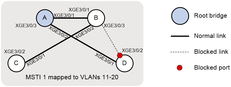
Based on the output, you can get the topology of MSTI 1, as shown in Figure 3.
Figure 3 Topology of MSTI 1
# Display dynamic VLANs on Device C.
[DeviceC] display vlan dynamic
Dynamic VLANs: 18
The dynamic VLANs include:
12-20, 22-30
# Display VLAN information on Ten-GigabitEthernet 3/0/2 of Device C.
[DeviceC] display interface ten-gigabitethernet 3/0/2
...
Port link-type: Trunk
VLAN Passing: 1(default vlan), 11, 21
VLAN permitted: 1(default vlan), 11-30
Trunk port encapsulation: IEEE 802.1q
...
The output shows that:
· VLANs 1, 11, and 21 can pass through Ten-GigabitEthernet 3/0/2.
· Ten-GigabitEthernet 3/0/2 failed to learn dynamic VLANs.
Configuration files
· Device A:
#
sysname DeviceA
#
mvrp global enable
#
vlan 1
#
vlan 11 to 30
#
stp region-configuration
region-name test
instance 1 vlan 11 to 20
instance 2 vlan 21 to 30
active region-configuration
#
stp instance 0 to 1 root primary
stp global enable
#
interface Ten-GigabitEthernet3/0/1
port link-mode bridge
port link-type trunk
port trunk permit vlan 1 11 to 30
mvrp enable
#
interface Ten-GigabitEthernet3/0/2
port link-mode bridge
port link-type trunk
port trunk permit vlan 1 11 to 30
mvrp enable
#
interface Ten-GigabitEthernet3/0/3
port link-mode bridge
port link-type trunk
port trunk permit vlan 1 11 to 30
mvrp enable
#
· Device B:
#
sysname DeviceB
#
mvrp global enable
#
vlan 1
#
vlan 11
#
vlan 21
#
stp region-configuration
region-name test
instance 1 vlan 11 to 20
instance 2 vlan 21 to 30
active region-configuration
#
stp instance 2 root primary
stp global enable
#
interface Ten-GigabitEthernet3/0/1
port link-mode bridge
port link-type trunk
port trunk permit vlan 1 11 to 30
mvrp enable
#
interface Ten-GigabitEthernet3/0/2
port link-mode bridge
port link-type trunk
port trunk permit vlan 1 11 to 30
mvrp enable
#
interface Ten-GigabitEthernet3/0/3
port link-mode bridge
port link-type trunk
port trunk permit vlan 1 11 to 30
mvrp enable
#
· Device C:
#
sysname DeviceC
#
mvrp global enable
#
vlan 1
#
vlan 11
#
vlan 21
#
stp region-configuration
region-name test
instance 1 vlan 11 to 20
instance 2 vlan 21 to 30
active region-configuration
#
stp global enable
#
interface Ten-GigabitEthernet3/0/1
port link-mode bridge
port link-type trunk
port trunk permit vlan 1 11 to 30
mvrp enable
#
interface Ten-GigabitEthernet3/0/2
port link-mode bridge
port link-type trunk
port trunk permit vlan 1 11 to 30
mvrp enable
#
· Device D:
#
sysname DeviceD
#
mvrp global enable
#
vlan 1
#
vlan 11
#
vlan 21
#
stp region-configuration
region-name test
instance 1 vlan 11 to 20
instance 2 vlan 21 to 30
active region-configuration
#
stp global enable
#
interface Ten-GigabitEthernet3/0/1
port link-mode bridge
port link-type trunk
port trunk permit vlan 1 11 to 30
mvrp enable
#
interface Ten-GigabitEthernet3/0/2
port link-mode bridge
port link-type trunk
port trunk permit vlan 1 11 to 30
mvrp enable
#