- Table of Contents
-
- H3C SR8800-X-S Router Series Installation Guide-5W103
- 00-Preface
- 01-Chapter 1 Preparing for Installation
- 02-Chapter 2 Installing the Router
- 03-Chapter 3 Installing FRUs
- 04-Chapter 4 Connecting Your Router to the Network
- 05-Chapter 5 Troubleshooting
- 06-Chapter 6 Replacement Procedures
- 07-Appendix A Chassis Views and Technical Specifications
- 08-Appendix B FRUs and Compatibility Matrixes
- 09-Appendix C LEDs
- 10-Appendix D Slot arrangement and port numbering
- 11-Appendix E Cables
- 12-Appendix F Cable Management
- 13-Appendix G Engineering Labels for Cables
- Related Documents
-
| Title | Size | Download |
|---|---|---|
| 02-Chapter 2 Installing the Router | 4.14 MB |
Confirming installation preparations
Attaching slide rails and cage nuts to the rack
Installing cable management bracket and mounting brackets
Installing the cable management bracket
(Optional) Installing an air filter
Mounting the router in the rack
Connecting the grounding cable to a grounding strip
Grounding the router through the PE wire of an AC power supply
Grounding the router through the RTN wire of a DC power supply
Installing the router
This section describes the procedure for installing the router.
|
|
NOTE: · The chassis and component views in this section are for illustration only. · Keep the packages of the router and components for future use. |
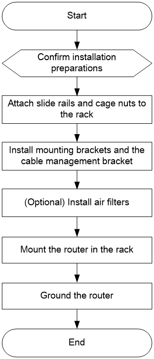
Installation flow
Confirming installation preparations
Before you install the router, verify that:
· You have read the chapter "Preparing for installation" carefully and the installation site meets all the requirements.
· A 19-inch rack is ready for use. For information about installing a rack, see the rack installation guide.
· The rack is sturdy and reliably grounded.
· No debris or obstacles exist inside or around the rack.
· Make sure the rack has enough space to accommodate the router. As a best practice to maintain the rack stability, install the router at the rack bottom. To mount multiple devices in a rack, install the heavier devices at the bottom.
· The available installation height of the rack is greater than the total height of the routers to be installed, and enough clearance is reserved for cable routing.
· The router is ready for installation and has been carried to a place near the rack and convenient for moving.
Attaching slide rails and cage nuts to the rack
Installing slide rails
Before mounting the router in a rack, install slide rails on the rack. If the rack has slide rails, skip this section.
Before installing slide rails in the rack, make sure the slide rails can support the weight of the router and its accessories. The SR8800-X-S routers are different in height. Determine the router installation position in the rack as required.
For the weights and dimensions of the SR8800-X-S routers, see "Weights and dimensions."
Table 1 describes the slide rails available for the router. For information about installing the slide rails, see the installation guide shipped with the slide rails.
Table 1 Slide rails available for the router
|
Router model |
Chassis weight with full configuration |
Available slide rails |
|||
|
Slide rail model |
Max. load-bearing capacity |
Adjustment range |
Occupied space |
||
|
SR8802-X-S |
29 kg (63.93 lb) |
LSXM1BSR |
450 kg (992.06 lb) |
630 to 900 mm (24.80 to 35.43 in) |
1 RU |
|
LSTM1KSGD0 |
280 kg (617.28 lb) |
300 to 500 mm (11.81 to 19.69 in) |
2 RU |
||
|
LSTM2KSGD0 |
360 kg (793.65 lb) |
500 to 800 mm (19.69 to 31.50 in) |
2 RU |
||
|
SR8803-X-S |
56 kg (123.46 lb) |
LSXM1BSR |
450 kg (992.06 lb) |
630 to 900 mm (24.80 to 35.43 in) |
1 RU |
|
LSTM1KSGD0 |
280 kg (617.28 lb) |
300 to 500 mm (11.81 to 19.69 in) |
2 RU |
||
|
LSTM2KSGD0 |
360 kg (793.65 lb) |
500 to 800 mm (19.685 to 31.50 in) |
2 RU |
||
|
SR8806-X-S |
74 kg (163.14 lb) |
LSXM1BSR |
450 kg (992.06 lb) |
630 to 900 mm (24.80 to 35.43 in) |
1 RU |
|
LSTM1KSGD0 |
280 kg (617.28 lb) |
300 to 500 mm (11.81 to 19.69 in) |
2 RU |
||
|
LSTM2KSGD0 |
360 kg (793.65 lb) |
500 to 800 mm (19.685 to 31.50 in) |
2 RU |
||
|
SR8810-X-S |
95 kg (209.44 lb) |
LSXM1BSR |
450 kg (992.06 lb) |
630 to 900 mm (24.80 to 35.43 in) |
1 RU |
|
LSTM1KSGD0 |
280 kg (617.28 lb) |
300 to 500 mm (11.81 to 19.69 in) |
2 RU |
||
|
LSTM2KSGD0 |
360 kg (793.65 lb) |
500 to 800 mm (19.685 to 31.50 in) |
2 RU |
||
Installing cage nuts
Before mounting the chassis in the rack, attach cage nuts to the front rack posts.
1. As shown in Figure 2, determine the positions of the cage nuts according to the holes on the mounting brackets and the positions of the slide rails.
2. Install cage nuts into the marked square holes on the front rack posts.
Figure 2 Determining the cage nut installation positions (SR8803-X-S)
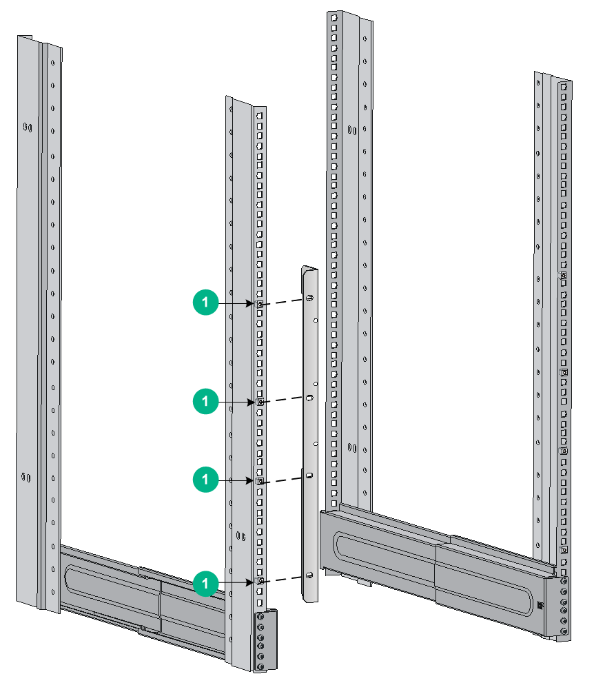
|
(1) Cage nut installation holes |
Installing cable management bracket and mounting brackets
Before installing the router in a rack, install the cable management bracket and mounting brackets shipped with the router. The cable management bracket is used for cabling the router, and mounting brackets are used for attaching the chassis to the rack.
Installing the cable management bracket
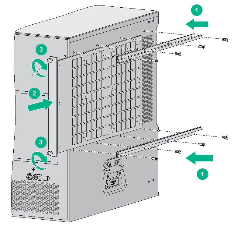
Attach the cable management bracket to the left mounting bracket, as shown in Figure 3. The router is supplied with two mounting brackets, and the one with the cable management bracket screw holes is the left mounting bracket.
Figure 3 Attaching the cable management bracket to the left mounting bracket (SR8803-X-S)
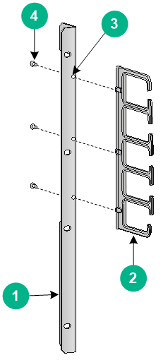
|
(1) Left mounting bracket |
(2) Cable management bracket |
|
(3) Screw hole for installing the cable management bracket |
|
|
(4) Screw for fixing the cable management bracket to the left mounting bracket |
|
Installing mounting brackets
To install the mounting brackets, as shown in Figure 4:
1. Face the front of the router, and mount the left mounting bracket to the left of the router.
2. Mount the right mounting bracket to the right of the router (where the fan tray is located).
Figure 4 Installing mounting brackets (SR8803-X-S)
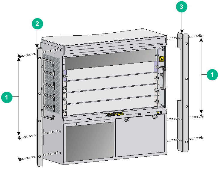
|
(1) Screws for fixing the mounting brackets to the chassis |
|
|
(2) Left mounting bracket |
(3) Right mounting bracket |
(Optional) Installing an air filter
Air filters are optional components for the router. If you have ordered an air filter, install the air filter before mounting the router in the rack.
To install the air filter:
1. Unpack the air filter and the metal rails.
2. Attach the metal rails to the left of the router. Align the mounting holes on the metal rails with the mounting holes above and below the inlet air vent, as shown by callout 1 in Figure 5.
3. Fasten the mounting screws to fix the metal rails.
4. Insert the air filter along the metal rails to the end, as shown by callout 2 in Figure 5.
5. Fasten the captive screws on the air filter, as shown by callout 3 in Figure 5.
Figure 5 Installing the air filter (SR8803-X-S)
Mounting the router in the rack
|
|
WARNING! · Do not hold the handle of a fan tray or power supply, air vents, or the handle on the real panel to move the router. Doing so might cause equipment damage or even bodily injury. · The router is heavy. As a best practice, use a mechanical lift to move it. · After placing the router on the slide rails, do not leave go of your hands immediately because this might tip the router, damaging the router or even causing bodily injury. |
To mount the router in the rack:
1. Move the chassis to face the rear of the chassis toward the front of the rack.
2. To lift the router, use a minimum of two persons or use a mechanical lift, if necessary. Lift the router until the bottom of the router is a little higher than the slide rails on the rack.
3. Gently place the router on the slide rails. Slide the router along the slide rails until the mounting brackets on the router touch the front rack posts, as shown by callout 1 in Figure 6.
4. Secure the chassis to the rack with screws shipped with the router.
Figure 6 Installing the chassis in a rack (SR8803-X-S)
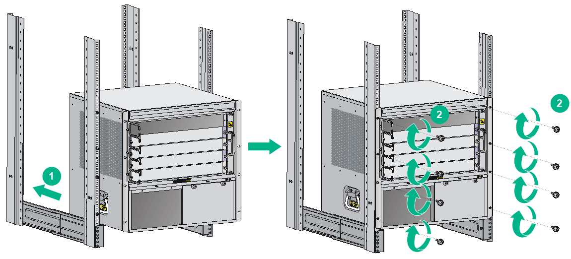
If the screw holes on the mounting brackets cannot align with the cage nuts on the rack, perform the following verifications:
· Verify that the bottom edge of the slide rail aligns with the middle of the narrowest metal area between holes.
· Verify that the cage nuts are installed in the correct holes.
Grounding the router
|
|
CAUTION: Before using the router, connect the grounding cable correctly to guarantee lightning protection and anti-interference of the router. |
Connecting the grounding cable to a grounding strip
|
|
CAUTION: · Use the supplied grounding cable (yellow-green grounding cable). · Connect the grounding cable to the grounding system in the equipment room. Do not connect it to a fire main or lightning rod. |
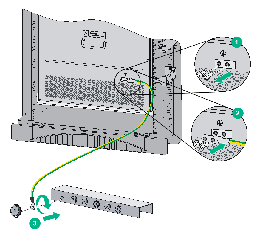
If a grounding strip is available at the installation site, connect the grounding cable through the grounding strip.
To connect the grounding cable:
1. Unpack the grounding cable.
The grounding cable provided with the router is compliant with the NEBS standards.
2. Remove the grounding screws from the grounding holes at the rear of the chassis, as shown by callout 1 in Figure 7.
3. Fasten the dual-hole grounding lug of the grounding cable to the grounding holes with the grounding screws, as shown by callout 2 in Figure 7.
4. Connect the ring terminal of the grounding cable to the grounding post of the grounding strip. Fasten the grounding cable to the grounding strip with the hex nut, as shown by callout 3 in Figure 7.
Figure 7 Connecting the grounding cable to a grounding strip
Grounding the router through the PE wire of an AC power supply
|
|
CAUTION: · Make sure the AC power supply uses a three-wire cable with a protection wire. · Make sure the PE wire of the AC power supply is correctly grounded at the power distribution room or AC power supply transformer side. · Make sure the PE connector on the router is correctly connected to the PE wire of the AC power supply. |
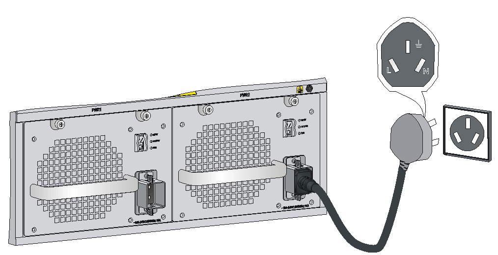
You can ground the router through the PE wire of the AC power supply, as shown in Figure 8, if the following conditions exist:
· The router is AC powered.
· No grounding strip is available at the installation site.
Figure 8 Grounding the router through the PE wire of the AC power supply
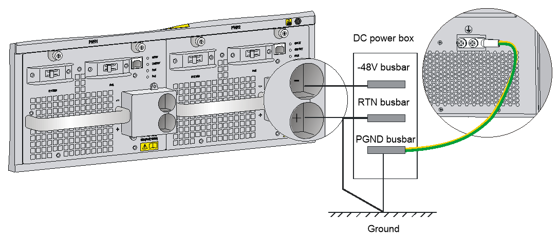
Grounding the router through the RTN wire of a DC power supply
|
|
CAUTION: Make sure the RTN wire is correctly grounded from the DC egress of the DC power cabinet. |
You can ground the router through the return (RTN) wire of the DC power supply, as shown in Figure 9, if the following conditions exist:
· The router is powered by a –48 VDC power supply.
· No grounding strip is available at the installation site.
Figure 9 Grounding the router through the RTN wire of the DC power supply