- Table of Contents
- Related Documents
-
| Title | Size | Download |
|---|---|---|
| 01-Text | 1.45 MB |
Examining the installation site
Temperature and humidity requirements
Grounding and lightning protection
Connecting the AP to a power source
Connecting a local power source
3 Connecting the AP to the network
Verifying that the AP has been connected to the network when it operates in fit mode
Verifying that the AP has been connected to the network when it operates in cloud mode
Logging in to the AP through Telnet
Logging in from the Web interface
5 Configuring the AP from the Cloudnet platform
Downloading and installing Cloudnet App Int
Logging in to the Cloudnet platform
1 Preparing for installation
|
|
WARNING! Install the AP under the guidance of technical engineers and read this chapter carefully before installation. |
Examining the installation site
Examine the installation site before installation to ensure that the AP will work in a good environment.
Installation site selection
The installation site must be selected according to the network planning and technical requirements of telecommunications equipment, with factors such as climate, hydrology, geology, earthquake, electric power, and transportation taken into consideration.
Determine the installation location by observing the following principles:
· The AP will not be exposed to moisture, high temperature, dust, harmful gases, electromagnetic interference sources (high power radars, radio stations, or electrical substations), unstable voltage, heavy vibration, and loud noise.
· The location is not water seeping, water soaking, and condensing.
· The location is away from inflammable and explosive substances.
· The AP uses built-in omnidirectional antennas. For the optimal coverage, make sure the installation height does not exceed 5 m (16.40 ft) and no obstacles exist around the AP.
Temperature and humidity requirements
Table1-1 Temperature and humidity requirements
|
Item |
Specification |
|
Operating temperature |
–35°C to +65°C (–31°F to +149°F) |
|
Storage temperature |
–40°C to +85°C (–40°F to +185°F) |
|
Operating humidity |
0% RH to 100% RH, noncondensing |
|
Storage humidity |
0% RH to 100% RH, noncondensing |
|
Protection rating |
IP67 |
Grounding and lightning protection
The AP must be reliably grounded. Make sure the grounding points of the grounding conductor of the AP, lightning arresters, PE wire of the power cord, and antenna support are separate from each other, make good contact, and are securely connected and treated with corrosion protection.
Ground resistance
The ground resistance is typically required to be less than 5 ohms, and less than 10 ohms in an area with less than 20 thunderstorm days a year. For a piece of angle steel buried in the earth as a grounding conductor, the ground resistance is required to be less than 10 ohms. In an area with a higher ground resistance, reduce the ground resistance by using brine or resistance reducing agent around the grounding conductor.
The top of the grounding conductor must be a minimum of 0.7 m (2.30 ft) away from the ground surface. In cold areas, the grounding conductor must be buried below the frozen soil layer.
Grounding conductor
If a grounding strip is available, connect the yellow and green grounding cable to the grounding strip. To make a grounding cable, make sure the cable has a cross-section area of greater than 3.3 mm2 (12 AWG) and a length of no longer than 3 m (9.84 ft).
If no grounding strip is available, bury a piece of angle steel/steel tube a minimum of 0.5 m (1.64 ft) long in the earth to act as the grounding conductor. It must be zinc-plated. In the case of a piece of angle steel, the size must be a minimum of 50 × 50 × 5 mm (1.97 × 1.97 × 0.20 in). In the case of a piece of steel tube, it must have a wall thickness of a minimum of 3.5 mm (0.14 in). Weld the grounding cable of the AP onto the grounding conductor and use anti-erosion treatment on the welding joint. With a cross-section area of greater than 3.3 mm2 (12 AWG), the grounding cable must be as short as possible and must not be coiled.
Make sure the grounding terminals of all the lightning arresters of the AP and the peer devices of the AP are reliably grounded.
Ground lead
A ground lead is a metal conductor connecting a grounding net and a grounding strip. The grounding cable of the AP must be connected to the grounding strip. The ground lead must be 30 m (98.43 ft) or shorter. A piece of zinc-coated flat steel with a cross-section area of 40 × 4 mm (1.57 × 0.16 in) or 50 × 5 mm (1.97 × 0.20 in) is recommended. Connect the grounding strip and the ground lead of the AP through the yellow and green grounding cable with an area of 35 mm2 (0.05 in2), or weld them directly. Use anti-erosion treatment on the welding joint.
Power grounding (AC)
Use a power cord with a protective earth (PE). Do not use a power cord with only an L line and an N line.
The neutral line of the power cord must not be connected with the PGND of other communications equipment. The L and N lines cannot be connected.
Lightning rod
The lightning protection grounding (for example, the grounding of the lightning rod) must be connected to the grounding conductor of the equipment room.
The lightning rod must be installed high enough to protect the AP and its antennas.
In plain areas, the shielding angle of the lightning rod must be less than 45 degrees. In mountainous areas or lightning areas, the shielding angle must be less than 30 degrees.
Ethernet cable
Use a shielded twisted pair cable for outdoor installation. Make sure the devices at the two ends of the cable are reliably grounded.
If a metal tube is used, make sure the Ethernet cable is reliably grounded at both ends of the tube.
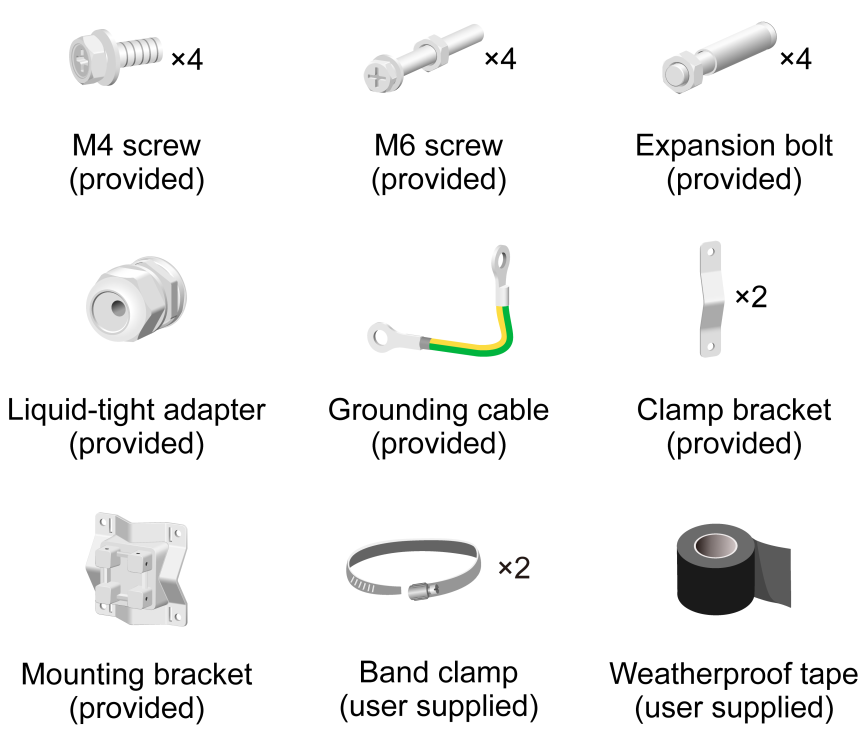
Installation accessories
Figure1-1 Installation accessories
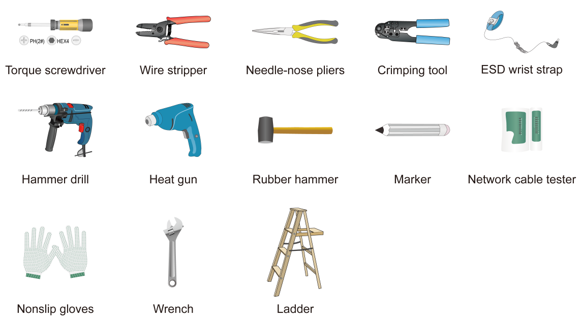
Installation tools
When installing the AP, you might need the following tools. Prepare the installation tools yourself as required.
Figure1-2 Installation tools
2 Installing the AP
|
|
IMPORTANT: As a best practice to ensure radio coverage, have the AP installed by technical personnel. |
Pre-installation tasks
Before installing an AP, perform the following tasks:
· Connect the AP to a power source and the network. Examine the LEDs to verify that the AP can operate correctly. For more information about the AP LEDs, see "Appendix B LEDs and ports".
· Verify that cabling at the installation site has been completed.
· Record the MAC address and serial number marked on the rear of the AP for future use.
Before installing the AP, read the following guidelines carefully:
· The AP is large and heavy. Avoid bodily injury and device damage during the installation.
· If you install the AP on a pole, make sure the pole is vertical to the ground and iron components have been treated with corrosion protection. Make sure the installation height and location of the AP meet the requirements.
· If you pole-mount the AP on the top of a building, make sure the AP does not project beyond the sides of the building.
· To avoid high temperature caused by exposure to the sun, install the AP in a place without or with little direct sunlight and take protection measures if necessary.
Before connecting cables to the AP, read the following guidelines carefully:
· Route cables according to the cabling design.
· Arrange cables firmly and neatly without crossing, twisting, or cracking them.
· Do not route cables together with high-voltage electric power pipelines, fire-fighting pipes, or lightning protection cables to avoid electromagnetic interference.
· Use PVC pipes, iron pipes, Plica tube, or cable troughs for cable routing. Route cable pipes and troughs neatly against the wall and connect them through hoses or pipe joints at the bend. Secure cable pipes and troughs by using cable ties or angle steels at the spacing of 1 m (3.28 ft) to 1.5 m (4.92 ft) and ground the two ends in the case of metal tubes.
· As a best practice to avoid water accumulation, cut an opening at the bottom of the PVC pipes every 6 m (19.69 ft) if you route cables by using PVC pipes.
· When routing cables outdoors without using cable casings, create drip loops on the cables to prevent the rainwater from flowing into the Ethernet ports of the device along the cables.
· Seal the holes for routing cables in the wall with waterproof and flame retardant material.
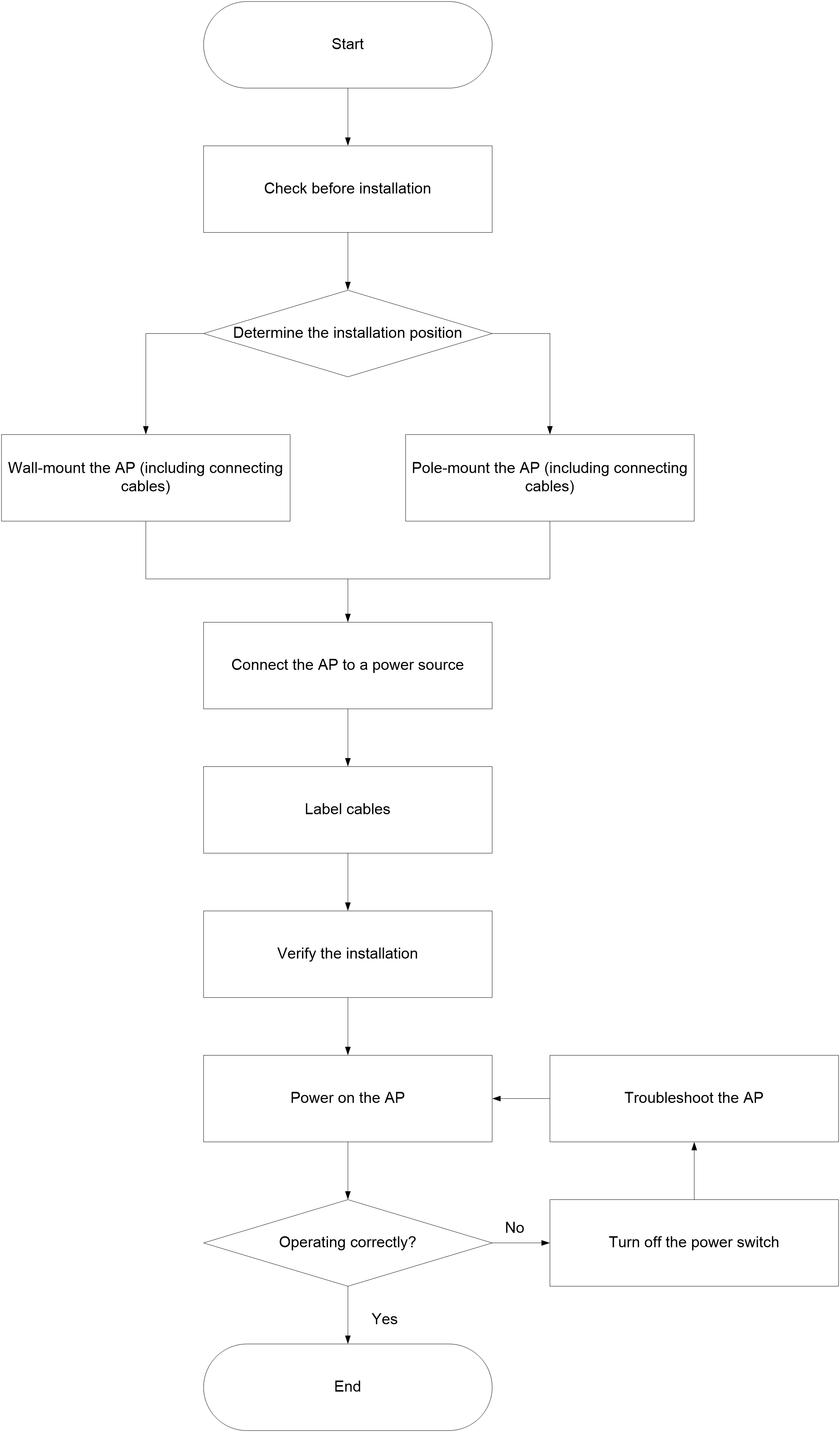
Installation flowchart
Figure2-1 Installation flowchart
Mounting the AP
The AP can be installed only outdoors. You can mount the AP on a wall or a pole.
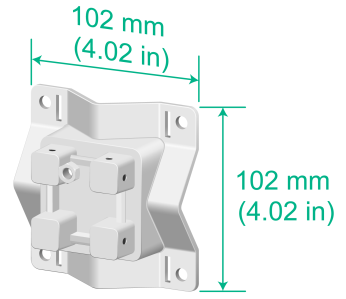
Mounting bracket
Figure2-2 Mounting bracket
Mounting the AP on a wall
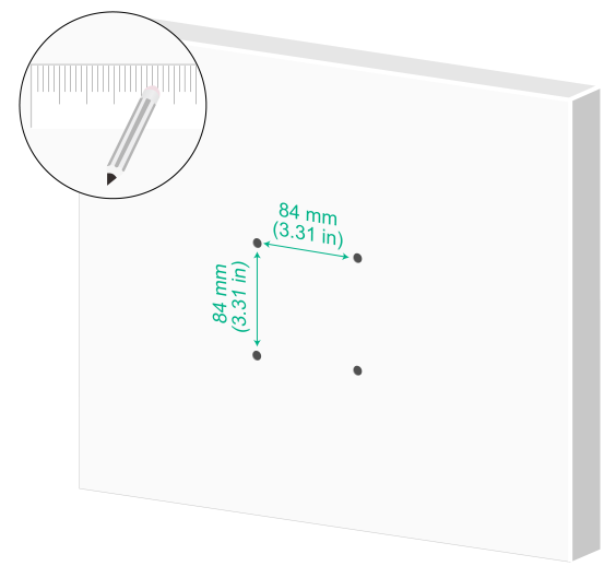
1. Mark the installation holes on the wall based on the installation hole positions in the AP.
Figure2-3 Marking the installation holes on the wall
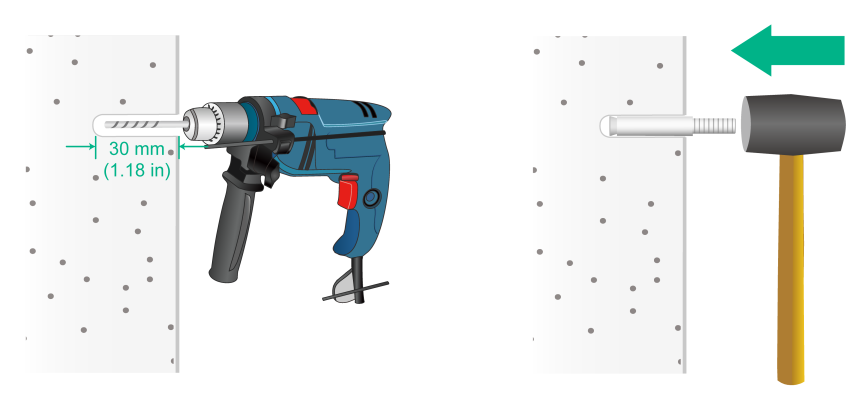
2. Drill four holes with a diameter of 8 mm (0.32 in) and a depth of 30 mm (1.18 in) at the marked locations. Use a rubber hammer to tap an expansion bolt into each hole.
¡ Keep the drill bit perpendicular to the wall and hold the drill handle tightly with both hands when drilling holes.
¡ In a sturdy and smooth wall, use a punch to create a hole to help locate the drill bit.
¡ The depth of the four holes must be the same.
¡ Do not tap the expansion bolts all the way in, leaving a certain space for hanging the AP.
Figure2-4 Hammering an expansion bolt into the wall
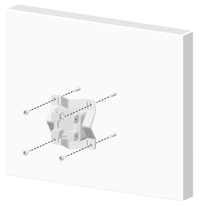
3. Hang the mounting bracket on the expansion bolts, and then fasten the screws to secure the mounting bracket to the wall.
Figure2-5 Securing the mounting bracket to the wall
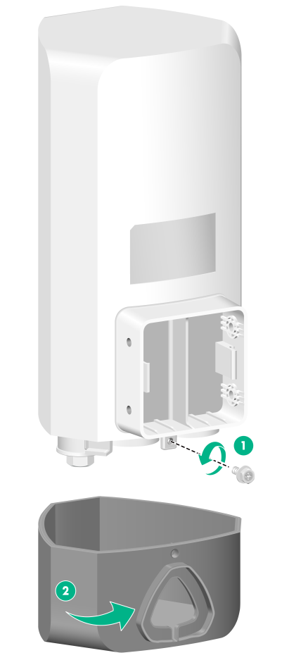
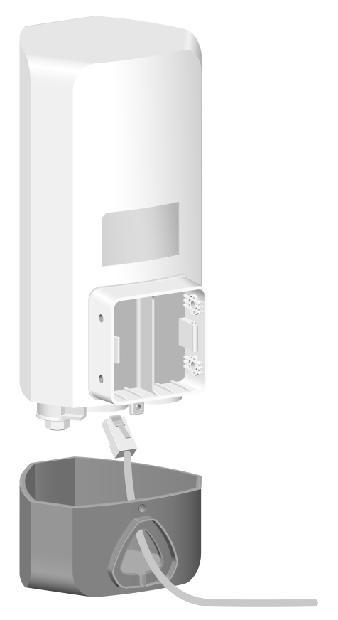
4. Remove the fastening (grounding) screw on the AP rear and base.
Figure2-6 Removing the fastening (grounding) screw and base
5. Feed the cables (including the Ethernet cable and power cord) through the triangular hole in the base, and then connect the cables to the AP.
For how to connect an Ethernet cable and install a liquid-tight adapter, see "Connecting an Ethernet cable."
For how to connect a power cord, see "Connecting the AP to a power source."
Figure2-7 Connecting a cable to the AP
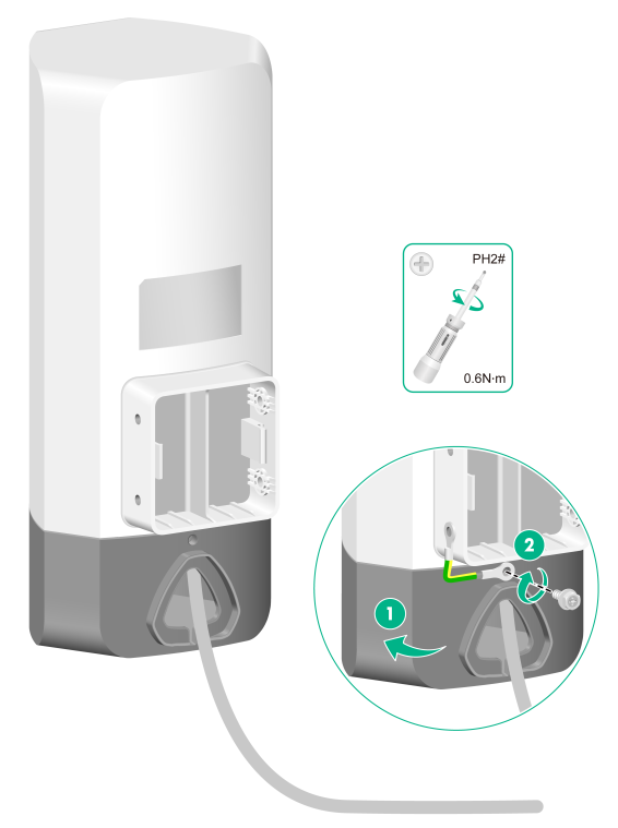
6. Use the fastening (grounding) screw to secure the base and one end of the grounding cable to the AP.
Correctly connecting the grounding cable is crucial to lightning protection and EMI protection.
Before connect the power cord to the AP, make sure the AP is reliably grounded. For more information, see "Grounding and lightning protection."
Figure2-8 Securing the base and one end of the grounding cable to the AP
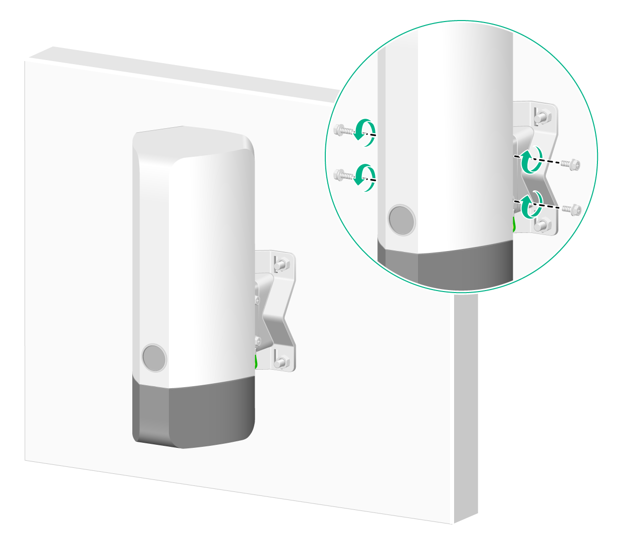
7. Use M4 screws to secure the device and the other end of the grounding cable to the mounting bracket.
Figure2-9 Securing the device and the other end of the grounding cable to the mounting bracket
Mounting the AP on a pole
For how to connect cables and the grounding cable to the AP and the connection order, see "Mounting the AP on a wall."
Typically, you can mount the AP on a vertical pole or a horizontal pole.
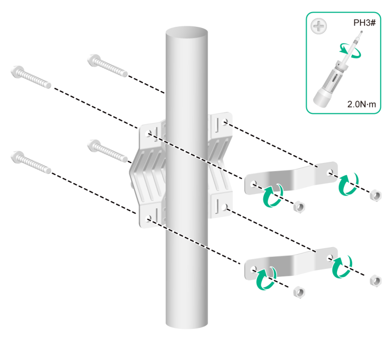
Mounting the AP on a vertical pole (by using a mounting bracket)
The provided mounting kit supports poles with a diameter of 30 to 60 mm (1.18 to 2.36 in).
To mount the AP on a vertical pole:
1. Use M6 screws to secure the mounting bracket and clamp brackets to the vertical pole.
Figure2-10 Securing the mounting bracket and clamp brackets to the vertical pole
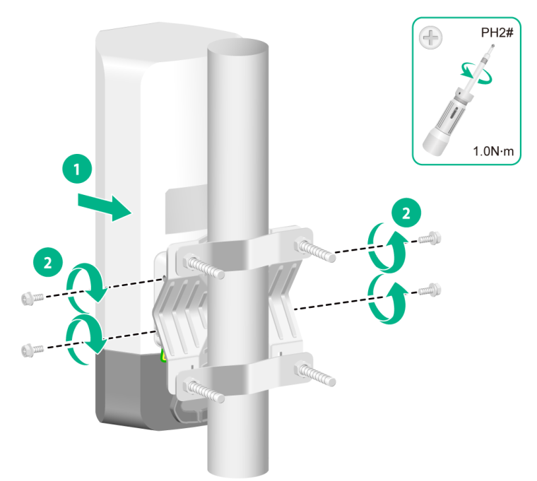
2. Use M4 screws to secure the AP to the mounting bracket.
Figure2-11 Securing the AP to the mounting bracket
Mounting the AP on a vertical pole (by using band clamps)
The band clamps support poles with a diameter of 60 to 200 mm (2.36 to 7.87 in). Prepare band clamps yourself as required.
To mount the AP on a vertical pole:
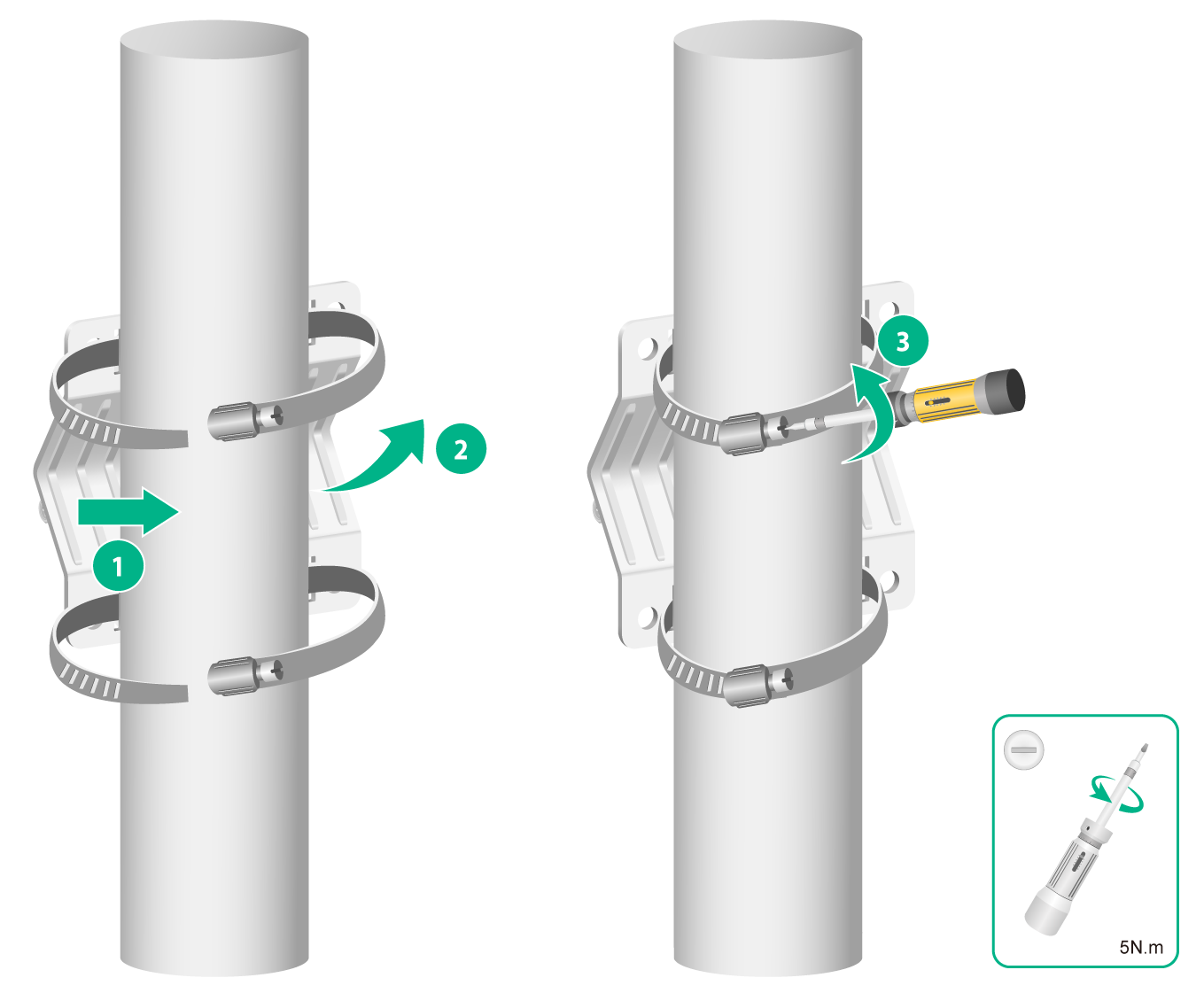
1. Use band clamps to secure the mounting bracket to the vertical pole.
Figure2-12 Securing the mounting bracket to the vertical pole
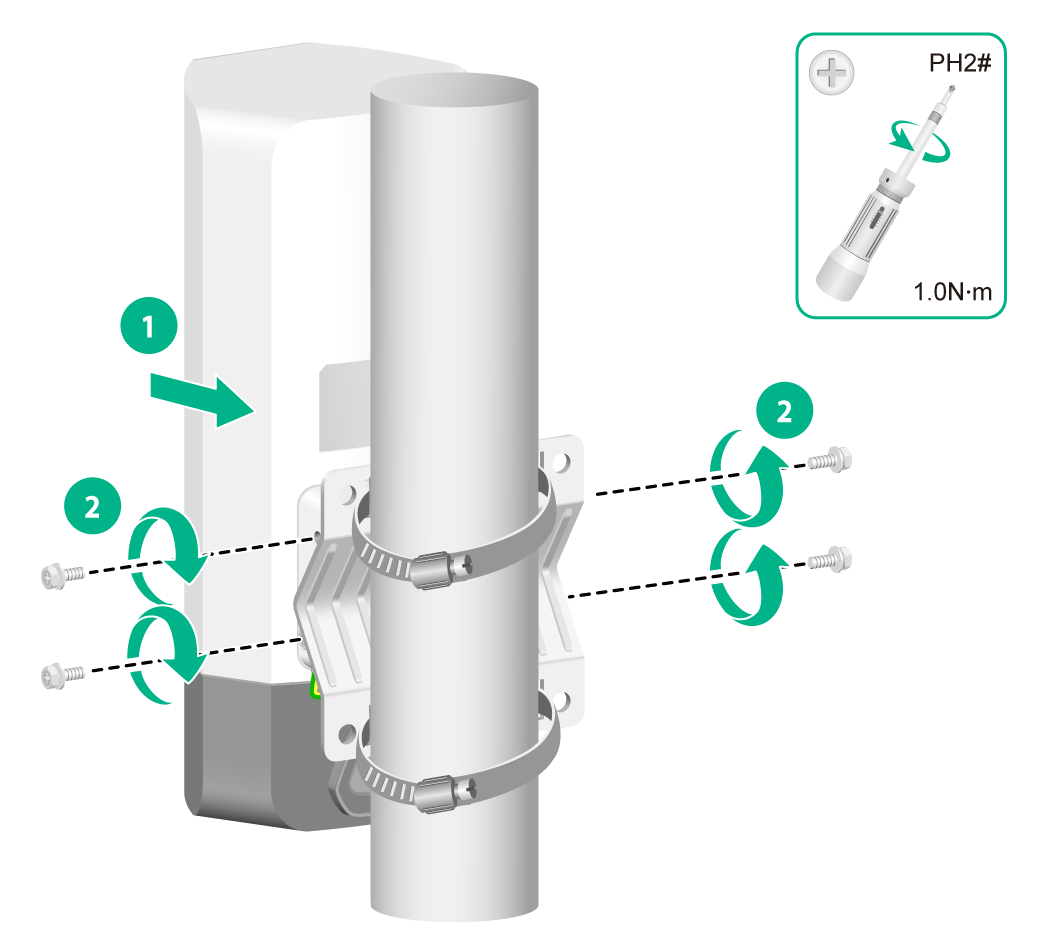
2. Use M4 screws to secure the AP to the mounting bracket.
Figure2-13 Securing the AP to the mounting bracket
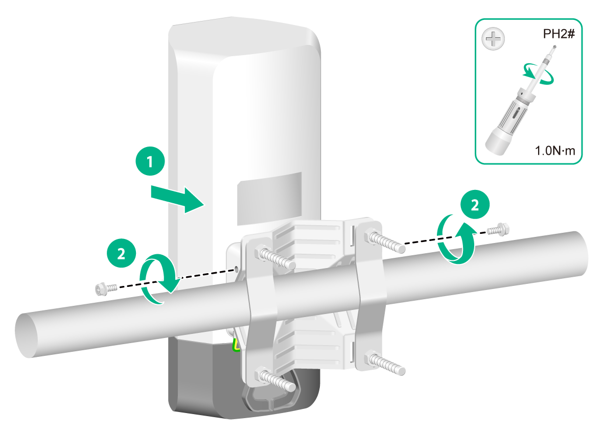
Mounting the AP on a horizontal pole (by using a mounting bracket)
The provided mounting kit supports poles with a diameter of 30 to 60 mm (1.18 to 2.36 in).
To mount the AP on a horizontal pole:
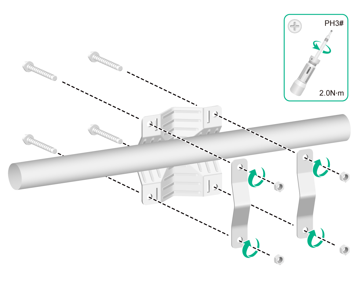
1. Use M6 screws to secure the mounting bracket and clamp brackets to the horizontal pole.
Figure2-14 Securing the mounting bracket and clamp brackets to the horizontal pole
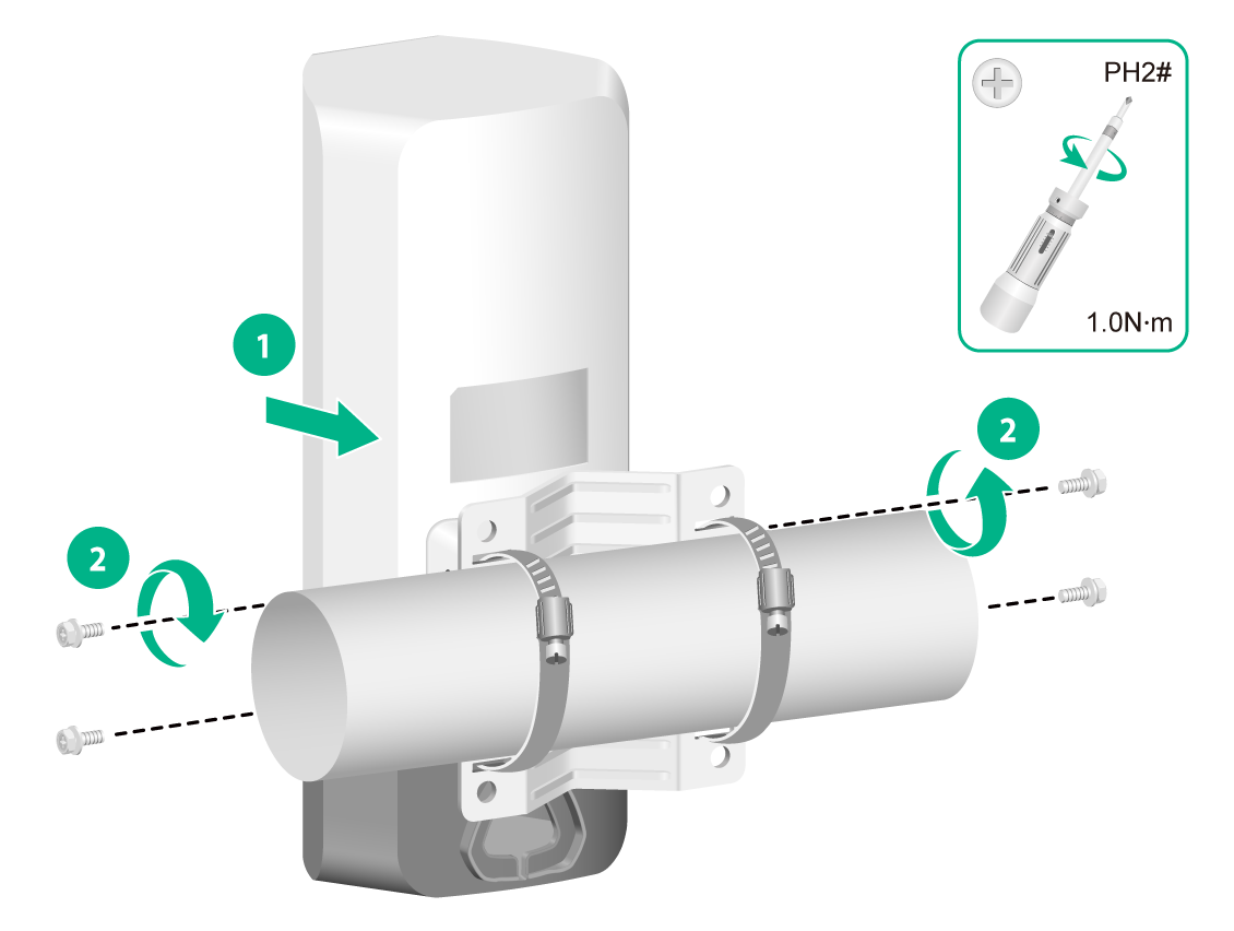
2. Use M4 screws to secure the AP to the mounting bracket.
Figure2-15 Attaching the AP to the mounting bracket
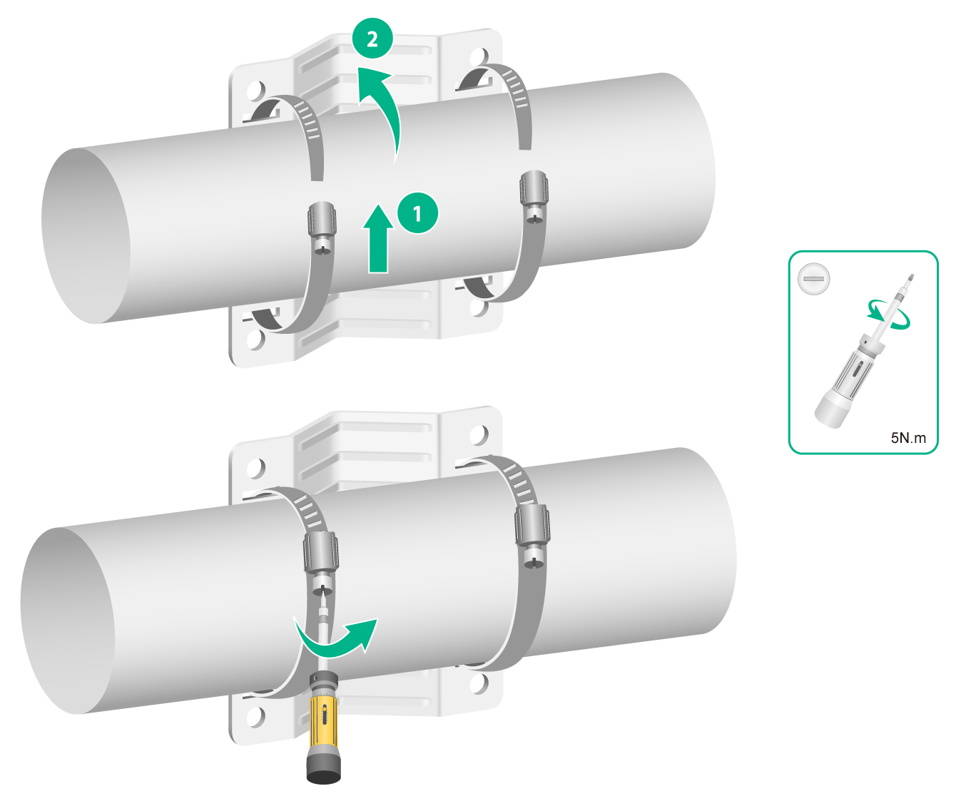
Mounting the AP on a horizontal pole (by using band clamps)
The band clamps support poles with a diameter of 60 to 200 mm (2.36 to 7.87 in). Prepare band clamps yourself as required.
To mount the AP on a horizontal pole:
1. Use band clamps to secure the mounting bracket to the vertical pole.
Figure2-16 Securing the mounting bracket to the horizontal pole
2. Use M4 screws to secure the AP to the mounting bracket.
Figure2-17 Securing the AP to the mounting bracket
Connecting an Ethernet cable
|
|
CAUTION: To avoid device damage, install weatherproof caps securely for unused ports. |
|
|
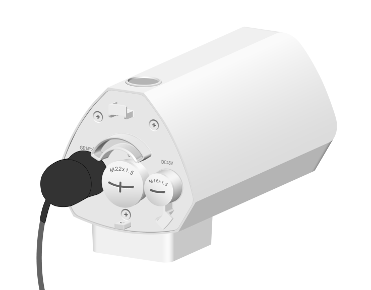
IMPORTANT: · Only the GE1 port on the AP supports PoE power supply. · Use Category-5e or above Ethernet cables only. As a best practice, use shielded twisted pair (STP) cables. · When you connect an Ethernet cable, do not remove the connector from the AP. |
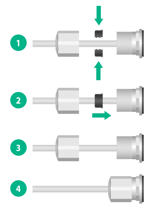
Figure2-18 Liquid-tight adapter
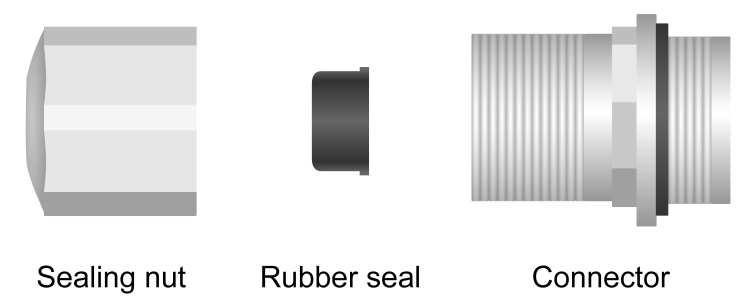
To connect an Ethernet cable:
1. Disassemble the liquid-tight adapter and put the rubber seal aside, and then feed the cable through the sealing nut.
2. Attach the rubber seal to the cable, and then insert the rubber seal into the connector.
3. Feed the cable connector through the connector of the liquid-tight adapter, and then connect the cable connector to the target Ethernet port on the AP.
4. Fasten the connector and the sealing nut.
5. Start wrapping at the top of the liquid-tight adapter until the entire liquid-tight adapter is wrapped. Smooth the tape edges to ensure full adhesion.
Figure2-19 Connecting an Ethernet cable
6. Route the cable outdoors.
¡ As a best practice to avoid water accumulation, cut an opening at the bottom of the PVC pipes every 6 m (19.69 ft) if you route the cable by using PVC pipes.
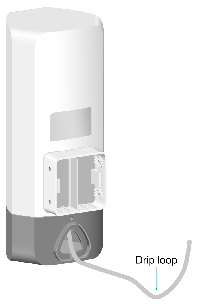
¡ If you route the cable outdoors without using cable casings, create drip loops on the cable to prevent rainwater from flowing into the Ethernet port of the device along the cable.
Figure2-20 Creating a drip loop
Connecting the AP to a power source
You can supply power to the AP by using a local power source or through 802.3at-compliant PoE. As a best practice, power the AP through PoE.
Before powering the AP, make sure the local power source or the 802.3at-compliant power sourcing equipment (PSE) is grounded reliably.
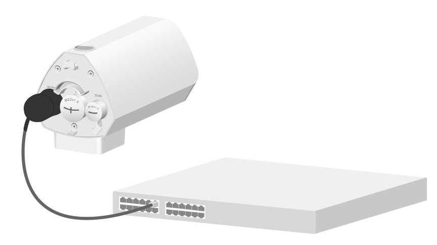
Connecting a PoE power source
To power the AP through PoE, use an Ethernet cable to connect an Ethernet port on a PoE switch to the GE1/PoE port on the AP.
Figure2-21 Connecting the AP to a PoE power source
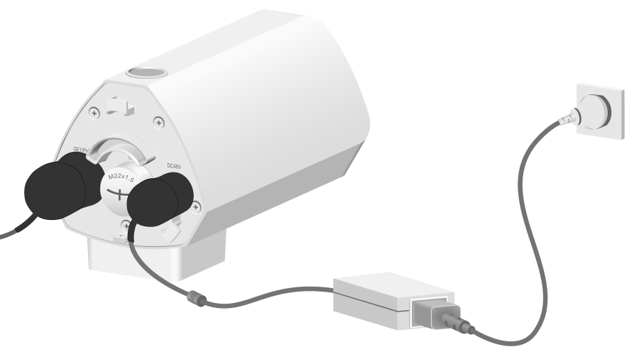
Connecting a local power source
|
|
CAUTION: To avoid device damage, make sure the weatherproof cap is installed securely on the power port if you do not supply power by using a local power source. |
Use a power adapter with outdoor lightning protection as the local power source. Install an M16 liquid-tight adapter on the power cord. For how to install a liquid-tight adapter, see "Connecting an Ethernet cable."
No M16 liquid-tight adapter or power adapter is provided with the AP. Prepare them yourself as required.
Table2-1 Power adapter specifications
|
Item |
Specification |
|
Input |
100 VAC to 240 VAC |
|
Output |
48 VDC to 54 VDC |
|
Output power |
> 20 W |
You can use an AC/DC power adapter to connect the AP to a local power source.
Figure2-22 Using a power adapter to connect the AP to a local power source
Labeling cables
After cable connection, attach labels to each cable as a best practice for future maintenance.
· Attach a label to both ends of a cable and every certain distance.
· Use cable flags or cable sleeves to label Ethernet cables.
· Use waterproof labels with clear content. Attach labels to proper places where they can be seen directly.
· Use transparent waterproof tape to seal outdoor labels.
Verifying the installation
After the installation is complete, check the following items before powering on the AP:
· The power source meets the power specification of the AP.
· The AP is grounded reliably.
· The Ethernet cables are connected correctly.
· The cables are labeled correctly.
· Weatherproof caps are installed securely for unused ports on the AP.
Powering on the AP
|
|
IMPORTANT: Make sure all cables are connected correctly and the AP is connected to the power source correctly before powering on the AP. |
Switch on the external power source and verify that the AP is operating correctly by examining the LEDs on the AP. For more information about the LEDs, see "Appendix B LEDs and ports."
3 Connecting the AP to the network
Verifying that the AP has been connected to the network when it operates in fit mode
When the AP operates in fit mode, all AP settings are configured on the AC. To verify the network connectivity of the AP, execute the display wlan ap all command on the AC. If the AP status is R/M, the AP has been connected to the network.
<Sysname> display wlan ap all
Total number of APs: 1
Total number of connected APs: 1
Total number of connected manual APs: 1
Total number of connected auto APs: 0
Total number of connected common APs: 1
Total number of connected WTUs: 0
Total number of inside APs: 0
Maximum supported APs: 3072
Remaining APs: 3071
Total AP licenses: 128
Remaining AP licenses: 127
AP information
State : I = Idle, J = Join, JA = JoinAck, IL = ImageLoad
C = Config, DC = DataCheck, R = Run M = Master, B = Backup
AP name APID State Model Serial ID
ap1 1 R/M WA6120X 219801A3WYP22A000001
Verifying that the AP has been connected to the network when it operates in cloud mode
When the AP operates in cloud mode, use a wireless terminal to search for and access the wireless service provided by the AP. If you can access external networks, the AP has been connected to the network.
4 Accessing the AP
When the AP operates in cloud mode, you can access and configure the AP from the Web interface, or through Telnet. Accessing the AP from the Web interface or through Telnet requires the IP address of the AP.
Logging in to the AP through Telnet
By default, HTTP and HTTPS are enabled and the following login information is defined for your login:
· Username—admin.
· Password—h3capadmin.
When the AP operates in cloud mode, only wireless connections are available.
Some Intel wireless adapters do not support 802.11ax. For clients to detect Wi-Fi 6 networks, upgrade the driver for the wireless adapter to the most recent version. For more information, see the official statement of Intel.
To log in to the AP through a wireless connection:
1. Enable WLAN on the configuration terminal and access WLAN H3C_xxxxxx, where xxxxxx is the last six bits of the AP's MAC address.
2. Enter telnet wlan.h3c.com from the CLI of the terminal.
3. Enter the default username and password.
Logging in from the Web interface
By default, HTTP and HTTPS are enabled and the following login information is defined for your login:
· Username—admin.
· Password—h3capadmin.
When the AP operates in cloud mode, only wireless connections are available. The configuration terminal must be enabled with DHCP.
Some Intel wireless adapters do not support 802.11ax. For clients to detect Wi-Fi 6 networks, upgrade the driver for the wireless adapter to the most recent version. For more information, see the official statement of Intel.
To log in to the AP through a wireless connection:
1. Enable WLAN on the configuration terminal and access WLAN H3C_xxxxxx, where xxxxxx is the last six bits of the AP's MAC address.
2. Visit http://wlan.h3c.com from a browser, and then press Enter.
3. Enter the default username and password. For security purposes, change the password as prompted after you access the Web interface, and then click OK
5 Configuring the AP from the Cloudnet platform
You can manage the AP remotely from the Cloudnet platform (Web interface or app) only when the AP operates in cloud mode.
Downloading and installing Cloudnet App Int
Make sure the smartphone uses Android 4.0, iOS7.0, or a higher-version operating system.
Download and install Cloudnet App Int from Google Play Store.
Logging in to the Cloudnet platform
To manage the AP from the Cloudnet platform, make sure the AP uses an IP address that can reach the external network.
To log in to the Cloudnet platform:
1. Open Cloudnet App Int or visit https://oasiscloudnet.h3c.com from a browser.
2. Enter the username and password.
After login, you can add the AP to the platform and manage the AP. For more information about platform login and device management, see H3C Cloudnet Deployment Guide.
