- Table of Contents
- Related Documents
-
| Title | Size | Download |
|---|---|---|
| 02-Installing the device | 1.13 MB |
Contents
Confirming installation preparations
Mounting the device on a workbench
Installing the device in a 19-inch rack
(Optional) Installing network port lightning protectors
(Optional) Installing a surge protected power strip
Connecting the device to the network
Connecting the console cable and setting terminal parameters
2 Installing the device
|
|
WARNING! Keep the tamper-proof seal on a mounting screw on the chassis cover intact, and if you want to open the chassis, contact H3C Support for permission. Otherwise, H3C shall not be liable for any consequence caused thereby. |
Confirming installation preparations
Before you install the device, verify that you have read "Preparing for installation" carefully and the installation site meets all the requirements.
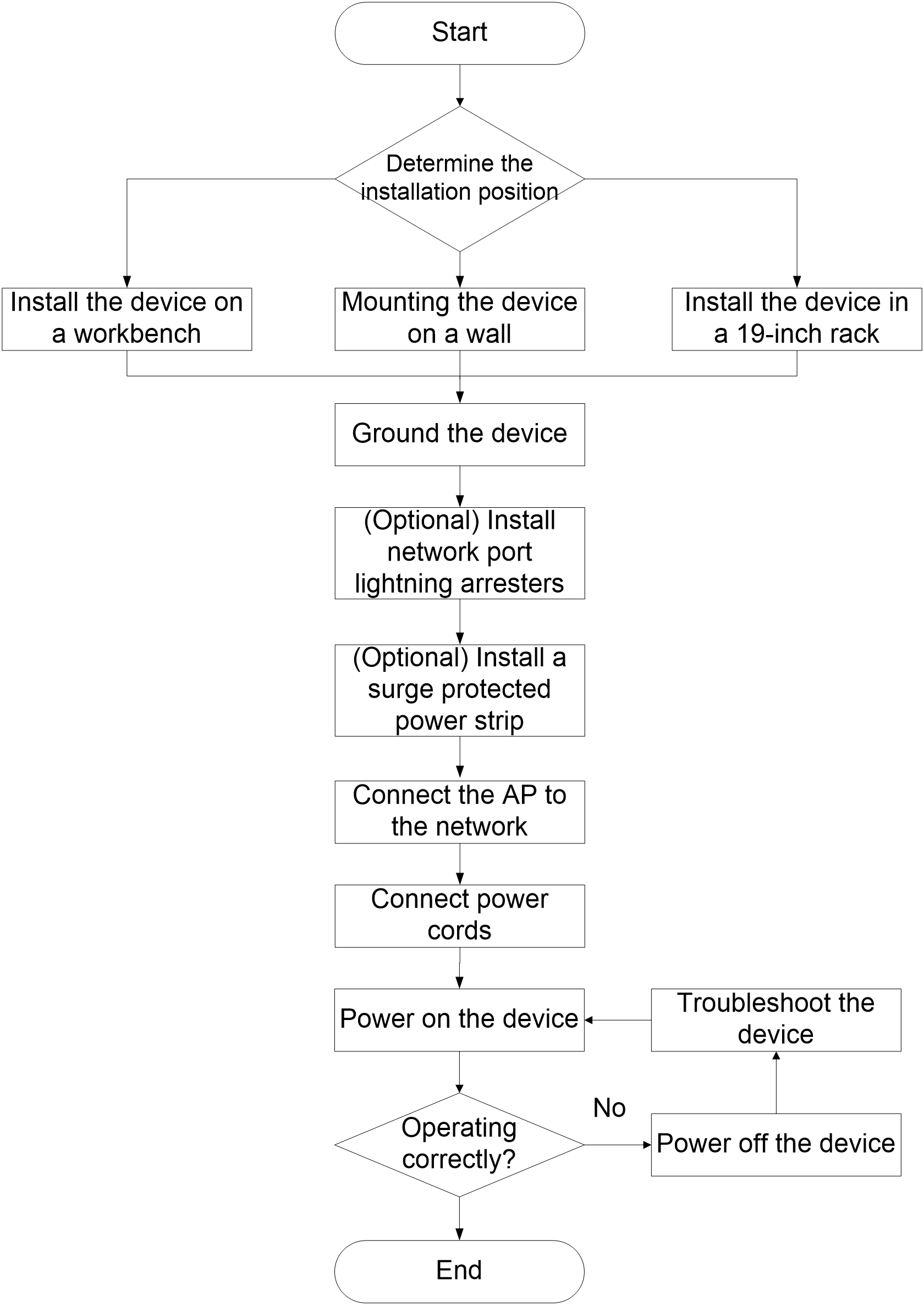
Installation flowchart
Figure2-1 Installation flowchart
Mounting the device on a workbench
|
|
CAUTION: Do not place heavy objects on the device. |
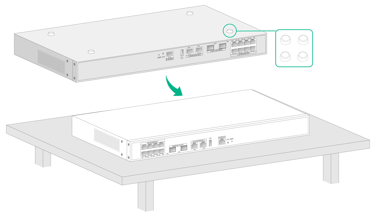
If a standard 19-inch rack is not available, you can mount the device on an anti-static workbench in the equipment room.
To mount the device on a workbench:
1. Place the device upside down. Clean the recessed areas on the chassis bottom.
2. Attach the four rubber feet to the recessed areas on the chassis bottom.
3. Place the device on the workbench with the upside up. Make sure the four rubber feet stand firmly on the workbench.
Figure2-2 Mounting the device on a workbench
Installing the device in a 19-inch rack
|
|
IMPORTANT: Keep a minimum distance of 1 U (44.45 mm, or 1.75 in) between devices in a rack for good heat dissipation. |
To install the device in a 19-inch rack in the equipment room by using mounting brackets:
1. Wear the ESD wrist strap and make sure the rack is sturdy and is grounded reliably.
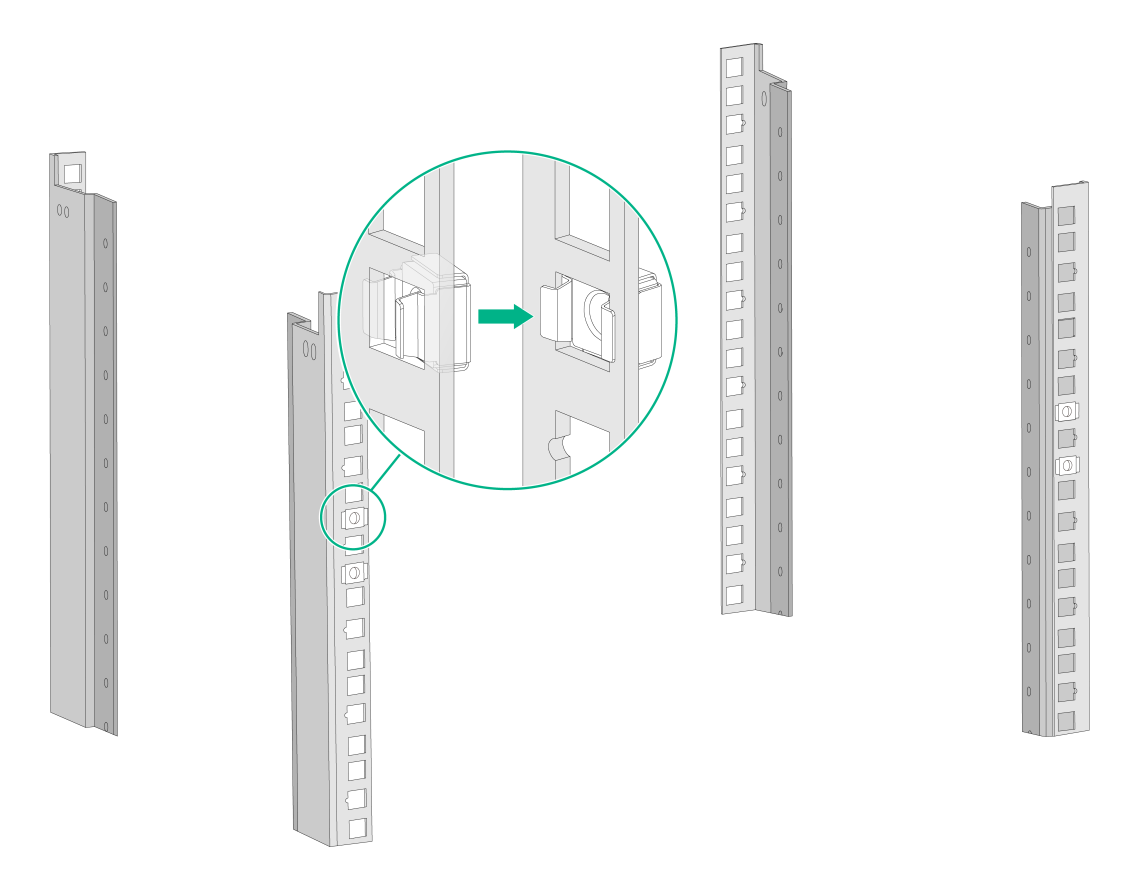
2. Attach cage nuts to the front rack posts:
a. Use a mounting bracket to mark cage nut installation positions on the two front rack posts.
b. Install cage nuts into the marked square holes on the front rack posts.
Figure2-3 Installing cage nuts
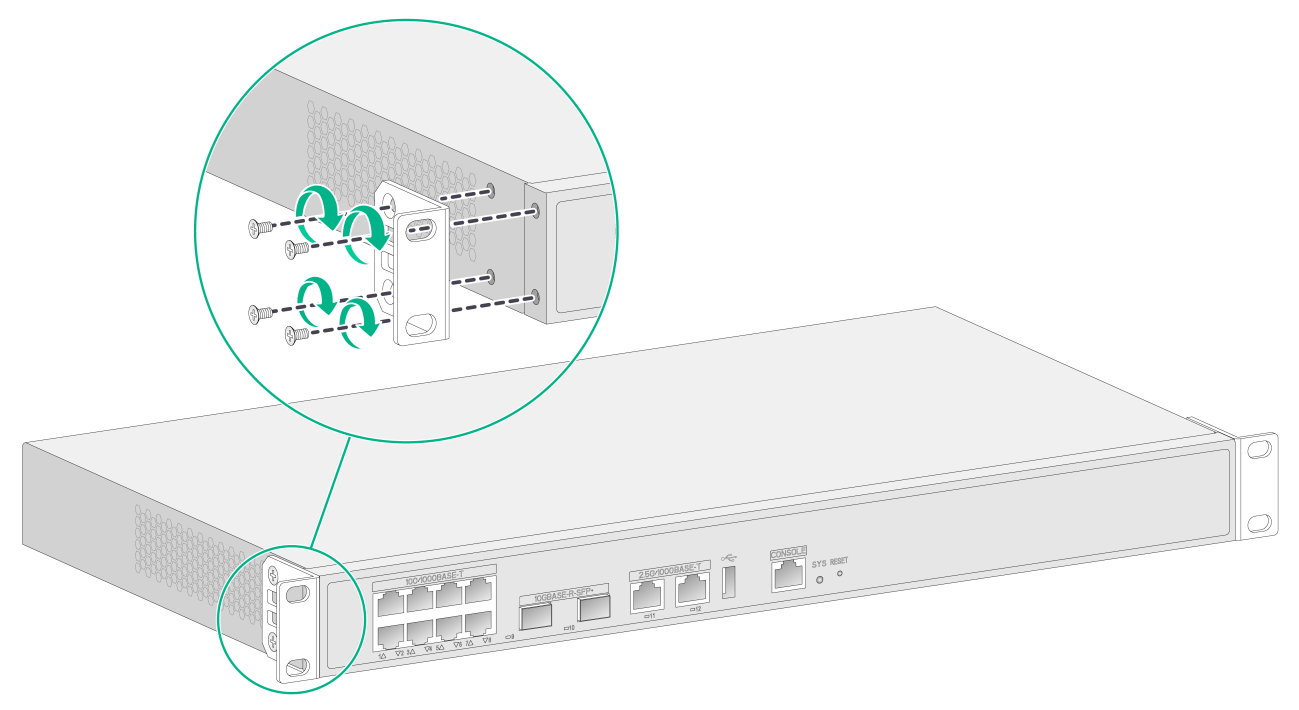
3. Unpack the M4 screws (packed with the mounting brackets), and then use the M4 screws to attach the mounting brackets to the device.
Figure2-4 Attaching the mounting brackets to the device
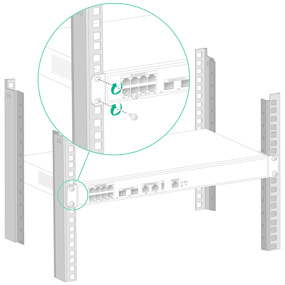
4. Supporting the device bottom with one hand and holding the device front with the other, push the device gently into the rack. Use M6 screws and matching cage nuts to attach the mounting brackets to the front rack posts. Make sure the device is installed in the rack securely.
Figure2-5 Attaching the mounting brackets to the front rack posts
Mounting the device on a wall
|
|
IMPORTANT: To mount the device on a wall, make sure its faceplate faces downwards. |
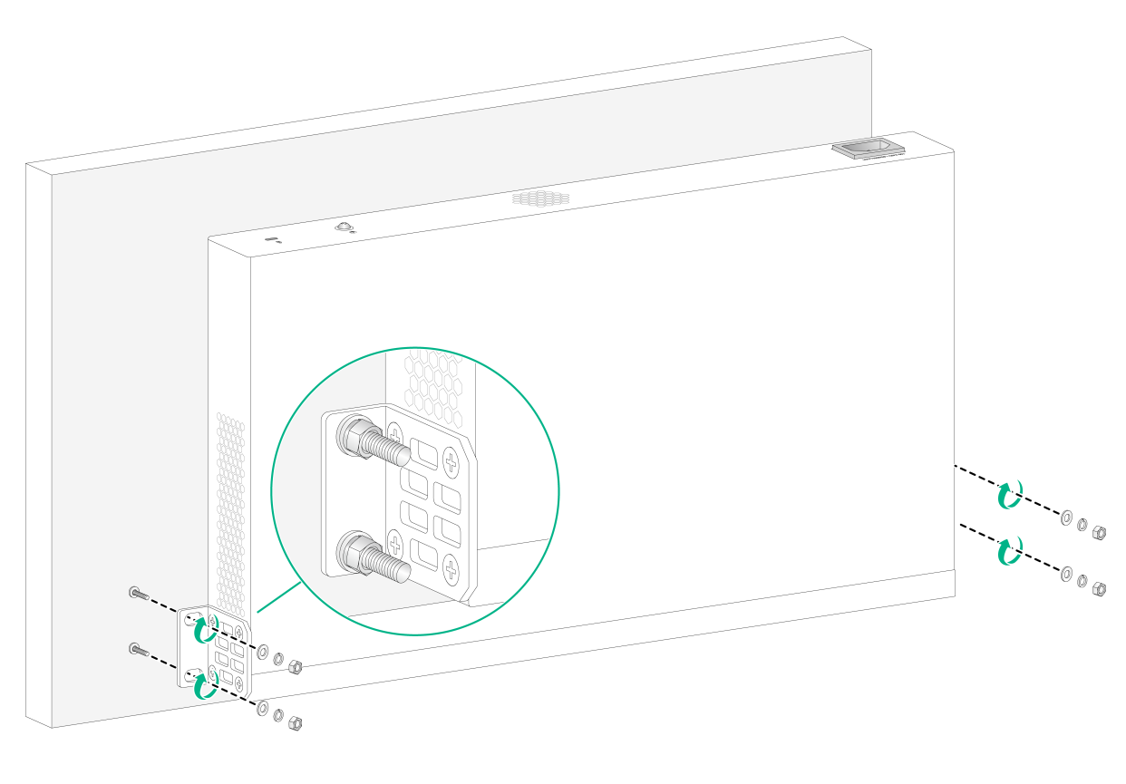
To mount the device on a wall:
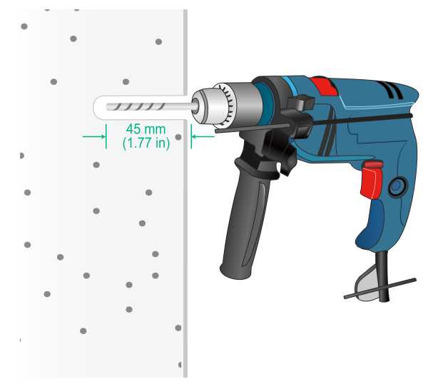
1. Drill four 8 mm (0.32 in) diameter holes at spacing shown in Figure2-6 in the wall.
Figure2-6 Installation hole spacing
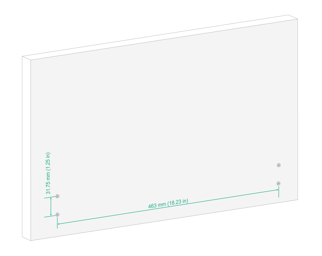
Figure2-7 Drilling installation holes
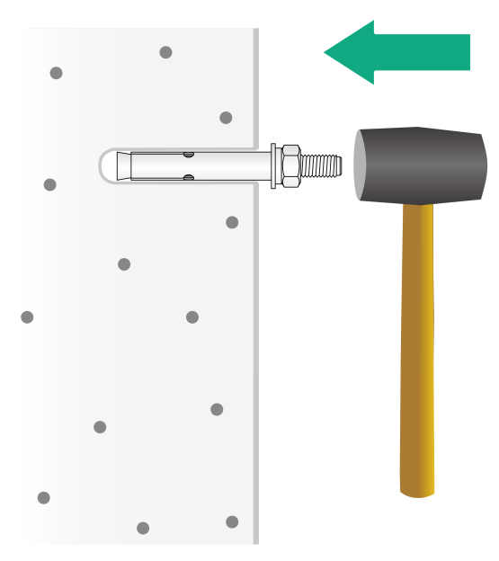
2. Hammer a wall anchor into each hole until the flat washer is flush with the wall and then remove the nut, spring washer, and flash washer from the anchor bolt in sequence.
Figure2-8 Hammering the wall anchor into the wall
3. Mount the device on the wall anchors by using the mounting brackets attached to the device and then install the flat washer, spring washer, and nut in sequence and then fasten the nut on the wall anchors.
Figure2-9 Mounting the device on the wall
Grounding the device
|
|
WARNING! · Correctly connecting the grounding cable is crucial to lightning protection and EMI protection. Before installing or using the device, connect the grounding cable for it correctly. · Connect the grounding cable to the grounding system in the equipment room. Do not connect it to a fire main or lightning rod. |
To ground the device:
1. Use a Phillips screwdriver to remove the grounding screw from the chassis rear panel.
2. Use the grounding screw to attach a ring terminal of the grounding cable to the chassis.
3. Use one of the following methods to connect the other end of the grounding cable:
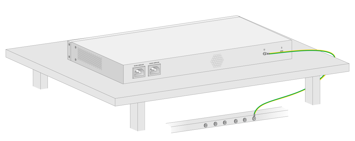
¡ Grounding the device by using a grounding strip
If a grounding strip is available, you can connect the other end of the grounding cable to the grounding strip. Make sure the grounding strip is grounded reliably.
Figure2-10 Grounding the device with a grounding strip
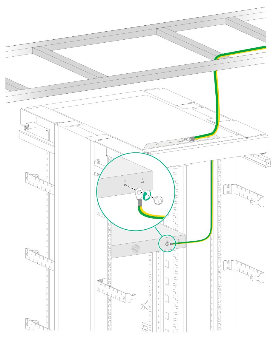
¡ Grounding the device through the rack
If the device is installed in a rack, you can connect the other end of the grounding cable to the grounding point on the rack. Make sure the rack is grounded reliably.
Figure2-11 Grounding the device through the rack
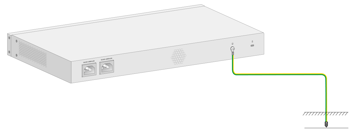
¡ Grounding the device with a grounding conductor buried in the earth
If earth is available at the installation site, you can ground the device with a grounding conductor buried in the earth.
Hammer a 0.5 m (1.64 ft) or longer angle iron or steel tube into the earth to serve as a grounding conductor. Weld the yellow-green grounding cable to the angel iron or steel tube and treat the joint for corrosion protection.
Figure2-12 Grounding the device by burying the grounding conductor into the earth
(Optional) Installing network port lightning protectors
|
|
CAUTION: If part of the network cable for a network port is routed outdoors, install a network port lightning protector for the port to protect against damages caused by lightning strikes. |
|
|
IMPORTANT: · Before installing a network port lightning protector, read the instructions in the document that comes with the protector. · Network port lightning protectors are available only for 100M/1000M RJ-45 Ethernet copper ports. · If multiple network ports have network cables routed outdoors, install a network port lightning protector for each network port. |
No network port lightning protectors are provided with the device. Purchase them yourself as required.
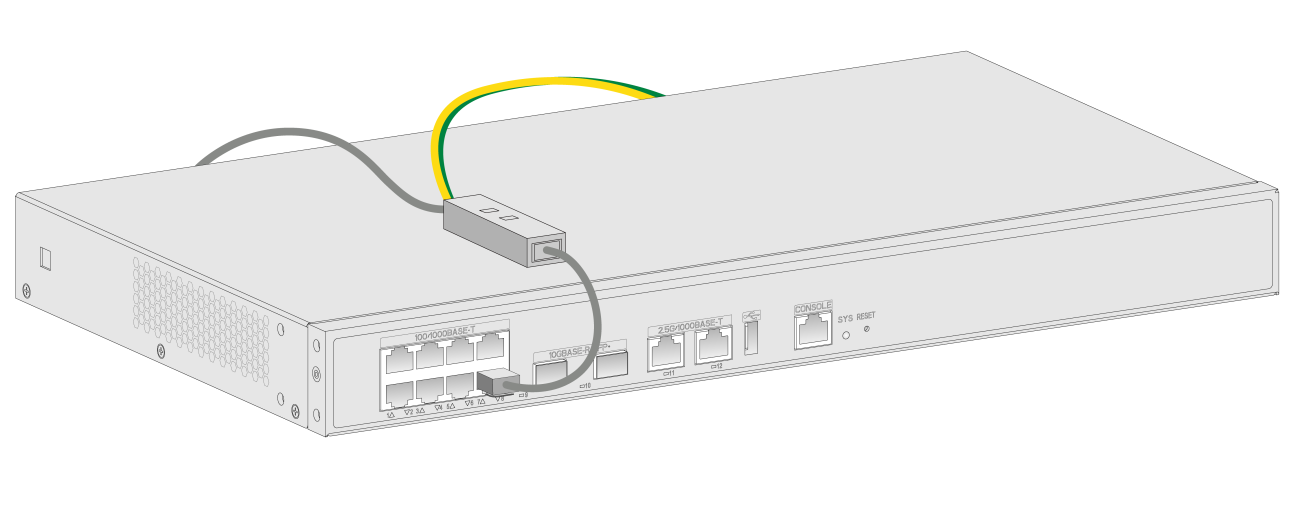
To install a network port lightning protector for a network port:
1. Use a double-faced adhesive tape to stick the network port lightning protector onto the device chassis, and make sure it is as close to the grounding screw of the device as possible.
2. Cut the ground wire of the protector to a length (as short as possible) as required by the distance between the protector and the grounding screw of the device. Attach the ground wire securely to the grounding screw of the device.
Make sure the grounding screw of the device is grounded reliably.
3. Use a multimeter to verify that the ground wire of the protector makes good contact with the grounding screw of the chassis.
4. Insert the outdoor network cable into the protector's Surge end marked IN, and insert the cable from the network port into the Protect end marked OUT.
5. Examine the port LED to verify that the port is operating correctly.
Figure2-13 Installing a lightning protector for a network port
(Optional) Installing a surge protected power strip
|
|
CAUTION: If you use an AC power line routed from outdoors for the device, use a surge protected power strip for the device to protect against damages caused by lightning strikes. |
|
|
IMPORTANT: Before installing a surge protected power strip, read the instructions in the document that comes with the strip. |
No surge protected power strip is provided with the device. Purchase one yourself as required.
To use a surge protected power strip, first connect the AC power line routed from outdoors to the strip and then connect the power cord from the device to the strip.
You can attach the surge protected power strip to the rack, workbench, or wall of the equipment room.
Connecting the device to the network
Connecting the console cable and setting terminal parameters
To configure and manage the device through the console port, you must run a terminal emulator program, TeraTermPro or PuTTY, on your configuration terminal. For more information about the terminal emulator programs, see the user guides for these programs
The following are the required terminal settings:
· Bits per second—9600.
· Data bits—8.
· Stop bits—1.
· Parity—None.
· Flow control—None.
Connecting Ethernet cables
Connecting an Ethernet copper port
1. Connect one end of the Ethernet cable to the Ethernet copper port on the device, and the other end to the Ethernet port on the peer device.
2. After powering on the device, examine the LEDs of the fixed Ethernet copper port.
For more information about the LED description, see "Appendix B LEDs."
Connecting a fiber port
|
|
WARNING! Do not stare into any open apertures of operating transceiver modules or optical fiber connectors. The laser light emitted from these apertures might hurt your eyes. |
|
|
CAUTION: · To connect a fiber port by using an optical fiber, first install a transceiver module in the port and then connect the optical fiber to the transceiver module. · Insert a dust cap into any open optical fiber connector and a dust plug into any open fiber port or transceiver module port to protect them from contamination and ESD damage. · Never bend an optical fiber excessively. The bend radius of an optical fiber must be not less than 10 cm (3.94 in). · Keep the fiber end clean. · Make sure the Tx and Rx ports on a transceiver module are connected to the Rx and Tx ports on the peer end, respectively. |
No transceiver modules are provided with the device. Purchase transceiver modules yourself as required. For more information about the transceiver modules, see "Appendix C Optional transceiver modules."
The fiber ports on the device support only LC connectors.
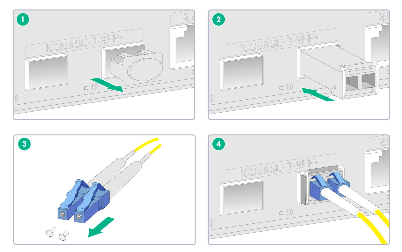
To connect an optical fiber for a fiber port:
1. Remove the dust plug from the fiber port.
2. Pivot the bail latch of the transceiver module up so that it catches a knob on the top of the transceiver module.
3. Holding both sides of the transceiver module, insert the transceiver module slowly into the port.
4. Identify the Rx and Tx ports on the transceiver module and remove the dust caps from the optical fiber connectors. Use the optical fiber to connect the Rx port and Tx port on the transceiver module to the Tx port and Rx port on the peer end, respectively.
5. Examine the port LEDs:
¡ If the LED is on, a fiber link has been set up.
¡ If the LED is off, the link has not been set up. The reason might be wrong connection of the Tx and Rx ends. Swap the fiber connectors in the Tx and Rx ports at one end of the fiber.
Figure2-14 Connecting an optical fiber
Connecting the power cord
|
|
WARNING! To avoid bodily injury, first connect the power cord to the device, and then connect the power cord to the power source in the equipment room. |
|
|
CAUTION: Before connecting the power cord, make sure the device is grounded correctly. |
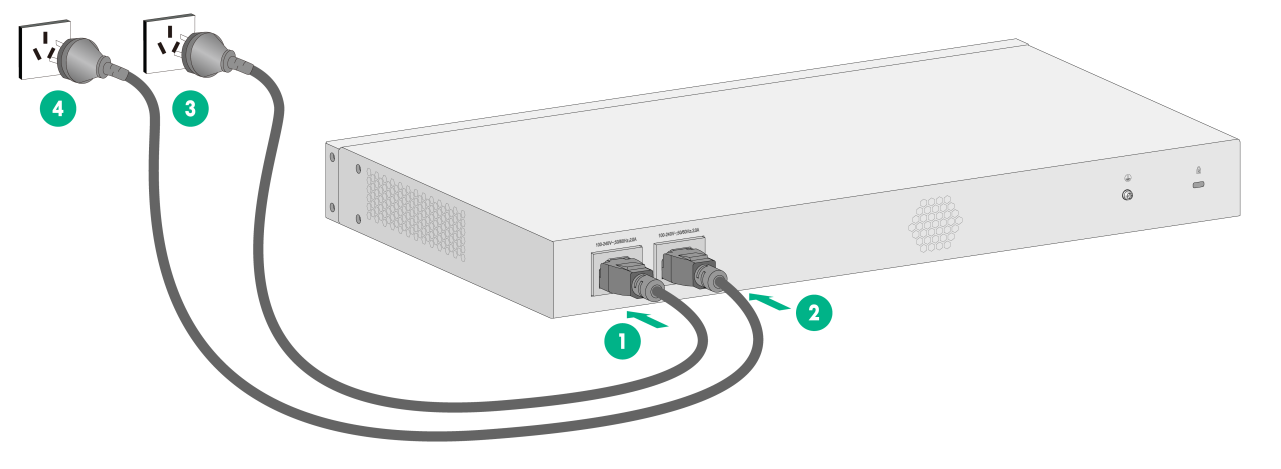
To connect the power cord:
1. Connect one end of the AC power cord to the AC-input power receptacle on the device.
2. Connect the other end of the AC power cord to the AC power source.
Figure2-15 Connecting the power cord
Verifying the installation
Before powering on the device, verify the following information:
· There is enough space around the device for heat dissipation.
· The work bench is sturdy.
· The grounding cable is securely connected.
· The Ethernet cables, optical fibers, and power cord are connected correctly.
· All the interface cables are cabled indoors. If any cable is routed outdoors, verify that the network port lightning protectors for network ports and surge protected power strip have been installed.
Powering on the device
1. Power on the device. The device initializes its memory and runs the BootWare. The following information appears on the terminal screen:
System is starting...
Press Ctrl+D to access BASIC-BOOTWARE MENU...
Press Ctrl+T to access BOOTWARE DIAG-TEST MENU
Booting Normal Extended BootWare
The Extended BootWare is self-decompressing....Done
****************************************************************************
* *
* H3C WX2880X BootWare, Version 1.07 *
* *
****************************************************************************
Copyright (c) 2004-2022 New H3C Technologies Co., Ltd.
Compiled Date : May 20 2022
Memory Type : DDR4 SDRAM
Memory Size : 4096MB
Memory Speed : 1200MHz
flash Size : 7456MB
CPLD Version : 002
PCB Version : Ver.A
BootWare Validating...
Press Ctrl+B to access EXTENDED-BOOTWARE MENU...
2. Press Ctrl + B at the prompt within 4 seconds to access the Boot menu.
To access the Boot menu after the system enters the system image file reading and self-compressing process, restart the device.
Loading the main image files...
Loading file flash:/system.bin......Done.
Loading file flash:/boot.bin................Done.
Image file flash:/boot.bin is self-decompressing.......Done.
System image is starting...
Cryptographic algorithms tests passed.
Line con0 is available.
Press ENTER to get started.
3. Press Enter at the prompt, and you can configure the device when the prompt <H3C> appears.
