- Table of Contents
-
- 10-MPLS Configuration Guide
- 00-Preface
- 01-Basic MPLS configuration
- 02-Static LSP configuration
- 03-LDP configuration
- 04-MPLS TE configuration
- 05-Static CRLSP configuration
- 06-RSVP configuration
- 07-Tunnel policy configuration
- 08-MPLS L3VPN configuration
- 09-MPLS L2VPN configuration
- 10-VPLS configuration
- 11-L2VPN access to L3VPN or IP backbone configuration
- 12-MPLS OAM configuration
- 13-MPLS protection switching configuration
- 14-MCE configuration
- Related Documents
-
| Title | Size | Download |
|---|---|---|
| 13-MPLS protection switching configuration | 140.47 KB |
Contents
Configuring MPLS protection switching
About MPLS protection switching
Protection switching triggering modes
Restrictions: Hardware compatibility with MPLS protection switching
MPLS protection switching tasks at a glance
Prerequisites for MPLS protection switching
Enabling MPLS protection switching
Specifying a traffic processing slot for the interface
Configuring protection switching attributes for the protection group
Configuring command switching for the protection group
Setting the PSC message sending interval
Restoring the default settings for a tunnel bundle interface
Display and maintenance commands for MPLS protection switching
MPLS protection switching configuration examples
Example: Configuring MPLS TE tunnel 1:1 protection switching
Configuring MPLS protection switching
About MPLS protection switching
MPLS protection switching provides an end-to-end linear protection mechanism for MPLS TE tunnels. It associates an MPLS TE tunnel (working tunnel) with another MPLS TE tunnel (protection tunnel) to form a protection group. When the working tunnel fails, traffic is immediately switched to the protection tunnel, ensuring continuous traffic forwarding.
Protection switching triggering modes
A failure on the working tunnel triggers a protection switching. Protection switching can also be triggered by a command or a signal fail indication.
· Command switching (external switching)—A protection switching is triggered by an externally configured switching command, which can define the following switching actions (in the descending order of priority):
¡ Clear—Clears all configured switching actions.
¡ Lockout of protection—Always uses the working tunnel to forward traffic.
¡ Forced switch—Forces traffic to be switched from the working tunnel to the protection tunnel.
¡ Manual switch—Manually switches traffic from the working tunnel to the protection tunnel. If a failure has occurred on the protection tunnel, traffic is not switched.
· Signal fail switching—A protection switching is automatically triggered by a signal fail indication. The signaling can be BFD detection for MPLS TE tunnels or interface state (up/down) detection through link layer. For more information about configuring BFD for MPLS TE tunnels, see "Configuring MPLS OAM."
The following shows the protection switching triggers in the descending order of priority:
· Clear.
· Lockout of protection.
· Forced switch.
· Signal fail on the protection tunnel—The signaling protocol detected a failure on the protection tunnel.
· Signal fail on the working tunnel—The signaling protocol detected a failure on the working tunnel.
· Clear signal fail—The signaling protocol detected that the working or protection tunnel has recovered.
· Manual switch.
If multiple triggers exist, the one with the highest priority determines the tunnel for traffic forwarding.
Protection switching modes
MPLS protection switching supports the following protection switching modes:
· 1:1 protection switching—Typically, traffic travels along the working tunnel. When either of the following events occurs, the ingress node selects the traffic forwarding tunnel (working or protection tunnel) according to the protection state:
¡ The ingress or egress node detects a failure on the working tunnel.
¡ An external switching command is executed on the node.
· 1+1 protection switching—Typically, traffic travels along both the working and protection tunnels, and the egress node receives traffic from the working tunnel. When either of the following events occurs, the egress node determines from which tunnel it receives traffic according to the protection state:
¡ The ingress or egress node detects a failure on the working tunnel.
¡ An external switching command is executed on the node.
|
|
NOTE: · The tunnel ingress or egress node can detect tunnel failures through BFD for MPLS or other detection mechanisms. For more information about BFD for MPLS, see "Configuring MPLS OAM." · The protection state indicates the comprehensive status of a protection switching protection group. For more information, see the display mpls forwarding protection command in MPLS Command Reference. |
Path switching modes
A bidirectional MPLS TE tunnel switches the traffic forwarding path in one of the following modes:
· Unidirectional path switching—When an external switching command or a signal fail triggers protection switching for traffic in one direction, protection switching switches the traffic forwarding tunnel only in this direction. The traffic forwarding tunnel in the other direction does not change.
· Bidirectional path switching—When an external switching command or a signal fail triggers protection switching for traffic in one direction, protection switching switches the traffic forwarding tunnels in both directions.
The ingress node and the egress node periodically send Protection State Coordination (PSC) packets to each other to coordinate the protection state. When one tunnel end performs a protection switching, the other end also performs a protection switching.
Protocols and standards
· RFC 6372, MPLS Transport Profile (MPLS-TP) Survivability Framework
· RFC 6378, MPLS Transport Profile (MPLS-TP) Linear Protection
Restrictions: Hardware compatibility with MPLS protection switching
|
Hardware |
MPLS protection switching compatibility |
|
MSR810, MSR810-W, MSR810-W-DB, MSR810-LM, MSR810-W-LM, MSR810-10-PoE, MSR810-LM-HK, MSR810-W-LM-HK, MSR810-LM-CNDE-SJK, MSR810-CNDE-SJK |
Yes |
|
MSR810-LMS, MSR810-LUS |
No |
|
MSR810-LMS-EA, MSR810-LME |
Yes |
|
MSR2600-6-X1, MSR2600-10-X1 |
Yes |
|
MSR 2630 |
Yes |
|
MSR3600-28, MSR3600-51 |
Yes |
|
MSR3600-28-SI, MSR3600-51-SI |
No |
|
MSR3600-28-X1, MSR3600-28-X1-DP, MSR3600-51-X1, MSR3600-51-X1-DP |
Yes |
|
MSR3610-I-DP, MSR3610-IE-DP, MSR3610-IE-ES, MSR3610-IE-EAD, MSR3610-I-IG, MSR3610-IE-IG |
Yes |
|
MSR3610-X1, MSR3610-X1-DP, MSR3610-X1-DC, MSR3610-X1-DP-DC |
Yes |
|
MSR 3610, MSR 3620, MSR 3620-DP, MSR 3640, MSR 3660 |
Yes |
|
MSR3610-G, MSR3620-G |
Yes |
|
Hardware |
MPLS protection switching compatibility |
|
MSR810-W-WiNet, MSR810-LM-WiNet |
Yes |
|
MSR830-4LM-WiNet |
Yes |
|
MSR830-5BEI-WiNet, MSR830-6EI-WiNet, MSR830-10BEI-WiNet |
Yes |
|
MSR830-6BHI-WiNet, MSR830-10BHI-WiNet |
Yes |
|
MSR2600-6-WiNet, MSR2600-10-X1-WiNet |
Yes |
|
MSR2630-WiNet |
Yes |
|
MSR3600-28-WiNet |
Yes |
|
MSR3610-X1-WiNet |
Yes |
|
MSR3610-WiNet, MSR3620-10-WiNet, MSR3620-DP-WiNet, MSR3620-WiNet, MSR3660-WiNet |
Yes |
|
Hardware |
MPLS protection switching compatibility |
|
MSR2630-XS |
Yes |
|
MSR3600-28-XS |
Yes |
|
MSR3610-XS |
Yes |
|
MSR3620-XS |
Yes |
|
MSR3610-I-XS |
Yes |
|
MSR3610-IE-XS |
Yes |
|
Hardware |
MPLS protection switching compatibility |
|
MSR810-LM-GL |
Yes |
|
MSR810-W-LM-GL |
Yes |
|
MSR830-6EI-GL |
Yes |
|
MSR830-10EI-GL |
Yes |
|
MSR830-6HI-GL |
Yes |
|
MSR830-10HI-GL |
Yes |
|
MSR2600-6-X1-GL |
Yes |
|
MSR3600-28-SI-GL |
No |
MPLS protection switching tasks at a glance
To configure MPLS protection switching, perform the following tasks:
1. Enabling MPLS protection switching
2. Creating a protection group
3. (Optional.) Specifying a traffic processing slot for the interface
4. (Optional.) Configuring protection switching attributes for the protection group
5. (Optional.) Configuring command switching for the protection group
6. (Optional.) Configuring signal switching for the protection group
The device supports automatic and manual protection switching.
Automatic protection switching is triggered by interface state.
To manually trigger protection switching, you must configure MPLS OAM on the working or protection tunnel to detect the tunnel state. For information about configuring MPLS OAM, see "Configuring MPLS OAM."
7. (Optional.) Setting the PSC message sending interval
8. Configuring traffic forwarding through the protection group
Select one of the following tasks:
¡ Configuring static routing to direct traffic to a tunnel bundle interface
¡ Configuring PBR to direct traffic to a tunnel bundle interface
¡ Configuring automatic route advertisement to direct traffic to a tunnel bundle interface
For more information, see "Configuring MPLS TE."
9. (Optional.) Restoring the default settings for a tunnel bundle interface
Prerequisites for MPLS protection switching
Before configuring MPLS protection switching, create two MPLS TE tunnels: one as the working tunnel, and the other as the protection tunnel. For information about creating an MPLS TE tunnel, see "Configuring MPLS TE."
Enabling MPLS protection switching
Restrictions and guidelines
Before you execute MPLS protection switching commands, you must enable MPLS protection switching.
Procedure
1. Enter system view.
system-view
2. Enable MPLS protection switching and enter its view.
mpls protection
By default, MPLS protection switching is disabled.
Creating a protection group
About this task
To create an MPLS TE protection group, perform the following tasks:
1. Create a tunnel bundle interface in protection switching mode.
2. Specify two member interfaces for the tunnel bundle interface by using the member interface command: one for the working tunnel, and the other for the protection tunnel.
In the protection group, the device determines the tunnel for traffic forwarding according to the external switching command and the signal fail.
Restrictions and guidelines
· The tunnel bundle interface is up after the IP address and tunnel destination address for the interface are configured and any one of its member interfaces is up.
· As a best practice, configure the same tunnel destination address for the tunnel bundle interface and its member interfaces. If they have different tunnel destination addresses, make sure the member interfaces have a route to the tunnel bundle interface. Otherwise, traffic forwarding will fail.
· The member interfaces for the tunnel bundle interface must be MPLS TE tunnel interfaces.
· The member interfaces forward only traffic whose output interface is the tunnel bundle interface.
Procedure
1. Enter system view.
system-view
2. Create a tunnel bundle interface in protection switching mode, and enter its view.
interface tunnel-bundle number protection { oneplusone | onetoone }
3. Specify a primary member interface.
member interface tunnel tunnel-number
By default, no primary member interface is specified.
The MPLS TE tunnel for a primary member interface is a working tunnel.
4. Specify a backup member interface.
member interface tunnel tunnel-number protection
By default, no backup member interface is specified.
The MPLS TE tunnel for a backup member interface is a protection tunnel.
5. Configure an IPv4 address for the tunnel bundle interface.
ip address ip-address { mask | mask-length } [ sub ]
By default, no IPv4 address is configured.
6. Configure the destination address for the tunnel bundle interface.
destination ip-address
By default, no tunnel destination address is configured.
7. (Optional.) Configure a description for the tunnel bundle interface.
description text
By default, the description for a tunnel bundle interface is Tunnel-Bundlenumber Interface, for example, Tunnel-Bundle1 Interface.
8. (Optional.) Set the expected bandwidth for the tunnel bundle interface.
bandwidth bandwidth-value
By default, the expected bandwidth of an interface is 64 kbps.
9. (Optional.) Bring up the tunnel bundle interface.
undo shutdown
By default, an interface is in up state.
Specifying a traffic processing slot for the interface
About this task
Specify a traffic processing slot if all traffic on a tunnel bundle interface is required to be processed on the same slot.
For high availability, you can specify one primary and one backup traffic processing slot by using the service command and the service standby command, respectively.
If you specify both primary and backup slots for an interface, traffic on that interface is processed as follows:
· The backup slot takes over when the primary slot becomes unavailable. The backup slot continues to process traffic for the interface after the primary slot becomes available again. The switchover will not occur until the backup slot becomes unavailable.
· When no specified traffic processing slots are available, the traffic is processed on the slot at which it arrives. Then, the processing slot that first becomes available again takes over.
If you do not specify a primary or a backup traffic processing slot for an interface, traffic on that interface is processed on the slot at which the traffic arrives.
Restrictions and guidelines
To avoid processing slot switchover, specify the primary slot before specifying the backup slot. If you specify the backup slot before specifying the primary slot, traffic is switched over to the primary slot immediately after you specify the primary slot.
Procedure
1. Enter system view.
system-view
2. Enter the view of the tunnel bundle interface in protection switching mode.
interface tunnel-bundle number protection { oneplusone | onetoone }
It is not required to specify the protection switching mode when you enter the view of an existing tunnel bundle interface.
3. Specify a primary traffic processing slot for the interface.
In IRF mode:
service slot slot-number
By default, no primary traffic processing slot is specified for an interface.
4. Specify a backup traffic processing slot for the interface.
In IRF mode:
service standby slot slot-number
By default, no backup traffic processing slot is specified for an interface.
Configuring protection switching attributes for the protection group
About this task
By default, when the working tunnel fails, traffic is immediately switched from the working tunnel to the protection tunnel to avoid traffic interruption. When the working tunnel recovers, traffic is immediately switched from the protection tunnel to the working tunnel. On an unstable network where the working and protection tunnels are up and down frequently, immediate switchovers might affect traffic forwarding and burden the device.
To resolve the problem, use the following methods:
· Delay switching—After the working tunnel fails, traffic is switched to the protection tunnel when the switching holdoff timer expires. Traffic is not switched to the protection tunnel if the working tunnel recovers within the holdoff time.
· Disable reverting—After the working tunnel recovers, the protection group continues to use the protection tunnel as long as the protection group is operating correctly.
· Delay reverting—After the working tunnel recovers, the wait timer starts. If the working tunnel is still operating correctly when the wait time expires, traffic is switched from the protection tunnel to the working tunnel.
Procedure
1. Enter system view.
system-view
2. Enter the view of a tunnel bundle interface in protection switching mode.
interface tunnel-bundle number [ protection { oneplusone | onetoone } ]
It is not required to specify the protection switching mode when you enter the view of an existing tunnel bundle interface.
3. Set the switching holdoff time when a working tunnel failure is detected.
protection holdoff holdoff-time
By default, the hold time is 0 seconds. When the working tunnel fails, traffic is immediately switched from the working tunnel to the protection tunnel.
4. Specify whether to switch traffic from the protection tunnel to the working tunnel when the working tunnel recovers, and set the wait time for the switchover.
protection revertive { never | wtr [ wtr-time ] }
By default, when the working tunnel recovers, traffic is immediately switched from the protection tunnel to the working tunnel.
5. Configure the protection group to use bidirectional path switching.
protection switching-mode bidirectional
This command can be configured only on the tunnel bundle interface in 1:1 protection switching mode.
By default, the protection group in 1:1 protection switching mode uses unidirectional path switching. The 1+1 protection switching mode supports only bidirectional path switching.
Configuring command switching for the protection group
About this task
This task allows you to trigger protection switching by executing an external switching command.
Procedure
1. Enter system view.
system-view
2. Enter the view of the tunnel bundle interface in protection switching mode.
interface tunnel-bundle number [ protection { onetoone | oneplusone } ]
It is not required to specify the protection switching mode when you enter the view of an existing tunnel bundle interface.
3. Configure a switching action.
protection switch { clear | force | lock | manual }
By default, no switching action is configured.
Setting the PSC message sending interval
About this task
The two ends of a tunnel periodically send PSC messages to coordinate the protection state for bidirectional path switching.
You can prevent PSC messages from occupying too much bandwidth and resources by modifying the sending interval as needed.
Procedure
1. Enter system view.
system-view
2. Enter MPLS protection switching view.
mpls protection
3. Set the PSC message sending interval.
psc message-interval interval
By default, the sending interval is 5 seconds.
Restoring the default settings for a tunnel bundle interface
Restrictions and guidelines
This task might affect the running services on the device. Before you perform this task, make sure you fully understand its impact on the network.
This task might fail to restore the default settings for some commands for reasons such as command dependencies or system restrictions. Use the display this command in interface view to identify these commands. Use their undo forms or follow the command reference to restore their default settings. If your restoration attempt still fails, follow the error message instructions to resolve the problem.
Procedure
1. Enter system view.
system-view
2. Enter the view of the tunnel bundle interface in protection switching mode.
interface tunnel-bundle number [ protection { onetoone | oneplusone } ]
It is not required to specify the protection switching mode when you enter the view of an existing tunnel bundle interface.
3. Restore the default settings for the tunnel bundle interface.
default
Display and maintenance commands for MPLS protection switching
Execute display commands in any view and reset commands in user view.
|
Task |
Command |
|
Display tunnel bundle interface information. |
display interface [ tunnel-bundle [ number ] ] [ brief [ description | down ] ] |
|
Display forwarding state information for MPLS protection groups. |
In standalone mode: display mpls forwarding protection [ tunnel-bundle number ] In IRF mode: display mpls forwarding protection [ tunnel-bundle number ] [ slot slot-number ] |
|
Display state and related information for MPLS protection groups. |
display mpls protection [ tunnel-bundle number ] [ verbose ] |
|
Display information about tunnel bundle interfaces and their member interfaces. |
display tunnel-bundle [ number ] |
|
Clear tunnel bundle interface statistics. |
reset counters interface [ tunnel-bundle [ number ] ] |
MPLS protection switching configuration examples
Example: Configuring MPLS TE tunnel 1:1 protection switching
Network configuration
Router A, Router B, Router C, and Router D run IS-IS.
Establish two MPLS TE tunnels (Tunnel 1 and Tunnel 2) from Router A to Router D to allow communication between two IP networks over the MPLS TE tunnels. Tunnel 1 uses the path Router A—Router B—Router D. Tunnel 2 uses the path Router A—Router C—Router D.
Configure protection switching on Router A by creating an MPLS protection group, and specify Tunnel 1 as the working tunnel and Tunnel 2 as the protection tunnel.
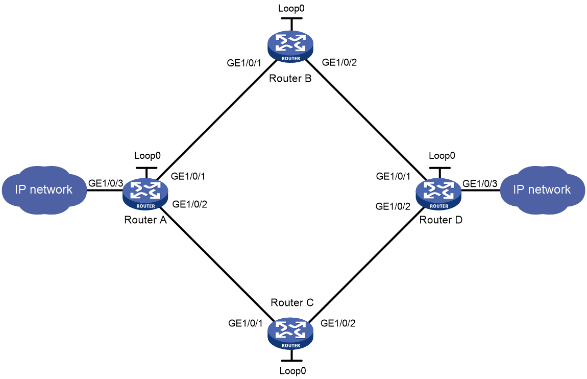
Table 1 Interface and IP address assignment
|
Device |
Interface |
IP address |
Device |
Interface |
IP address |
|
Router A |
Loop0 |
1.1.1.1/32 |
Router D |
Loop0 |
4.4.4.4/32 |
|
|
GE1/0/1 |
2.1.1.1/24 |
|
GE1/0/1 |
4.1.1.2/24 |
|
|
GE1/0/2 |
3.1.1.1/24 |
|
GE1/0/2 |
5.1.1.2/24 |
|
|
GE1/0/3 |
100.1.1.1/24 |
|
GE1/0/3 |
100.1.2.1/24 |
|
Router B |
Loop0 |
2.2.2.2/32 |
Router C |
Loop0 |
3.3.3.3/32 |
|
|
GE1/0/1 |
2.1.1.2/24 |
|
GE1/0/1 |
3.1.1.2/24 |
|
|
GE1/0/2 |
4.1.1.1/24 |
|
GE1/0/2 |
5.1.1.1/24 |
Procedure
1. Configure IP addresses and masks for interfaces as shown in Figure 1. (Details not shown.)
2. Create MPLS TE tunnels on Router A:
# Create two MPLS TE tunnels (Tunnel 1 and Tunnel 2) to Router D. For more information, see "Configuring MPLS TE."
# Display information about the two MPLS TE tunnels on Router A.
<RouterA> display mpls tunnel all
Destination Type Tunnel/NHLFE VPN Instance
4.4.4.4 CRLSP Tunnel1 -
4.4.4.4 CRLSP Tunnel2 -
# Display tunnel interface information on Router A. The output shows that the tunnel interface is up. This example uses Tunnel 1.
<RouterA> display interface tunnel 1
Tunnel1
Current state: UP
Line protocol state: UP
Description: Tunnel1 Interface
Bandwidth: 64kbps
Maximum transmission unit: 1496
Internet Address is 10.1.10.1/24 Primary
Tunnel source unknown, destination 4.4.4.4
Tunnel TTL 255
Tunnel protocol/transport CR_LSP
Output queue - Urgent queuing: Size/Length/Discards 0/100/0
Output queue - Protocol queuing: Size/Length/Discards 0/500/0
Output queue - FIFO queuing: Size/Length/Discards 0/75/0
Last clearing of counters: Never
Last 300 seconds input rate: 0 bytes/sec, 0 bits/sec, 0 packets/sec
Last 300 seconds output rate: 0 bytes/sec, 0 bits/sec, 0 packets/sec
Input: 0 packets, 0 bytes, 0 drops
Output: 0 packets, 0 bytes, 0 drops
3. Configure a tunnel bundle interface for the protection group:
# Enable MPLS protection switching.
<RouterA> system-view
[RouterA] mpls protection
[RouterA-mpls-protection] quit
# Create a tunnel bundle interface in 1:1 protection switching mode.
[RouterA] interface tunnel-bundle 0 protection onetoone
# Specify 4.4.4.4 (Router D's LSR ID) as the tunnel destination address.
[RouterA-Tunnel-Bundle0] destination 4.4.4.4
# Configure an IP address for the tunnel bundle interface. This example uses 101.1.101.1/24.
[RouterA-Tunnel-Bundle0] ip address 101.1.101.1 24
# Specify tunnel interface Tunnel 1 as the primary member interface, and Tunnel 2 as the backup member interface.
[RouterA-Tunnel-Bundle0] member interface tunnel 1
[RouterA-Tunnel-Bundle0] member interface tunnel 2 protection
[RouterA-Tunnel-Bundle0] quit
4. Configure BFD for the protection group:
# Enable BFD for MPLS.
[RouterA] mpls bfd enable
# Enable BFD for primary member interface Tunnel 1 to test the connectivity of the working tunnel.
[RouterA] interface tunnel 1
[RouterA-Tunnel1] mpls bfd
[RouterA-Tunnel1] quit
# Enable BFD for backup member interface Tunnel 2 to test the connectivity of the protection tunnel.
[RouterA] interface tunnel 2
[RouterA-Tunnel2] mpls bfd
[RouterA-Tunnel2] quit
# Display BFD information for the MPLS TE tunnels on Router A.
[RouterA] display bfd session
Total Session Num: 2 Up Session Num: 2 Init Mode: Active
IPv4 Session Working Under Ctrl Mode:
LD/RD SourceAddr DestAddr State Holdtime Interface
513/513 1.1.1.1 127.0.0.1 Up 2297ms Tunnel1
514/514 1.1.1.1 127.0.0.1 Up 1127ms Tunnel2
5. Configure a static route to 100.1.2.0/24 through Tunnel-Bundle 0.
[RouterA] ip route-static 100.1.2.0 24 tunnel-bundle 0 preference 1
Verifying the configuration
# Display information about the tunnel bundle interface and its member interfaces on Router A.
[RouterA] display tunnel-bundle
Total number of tunnel bundles: 1, 1 up, 0 down
Tunnel bundle name: Tunnel-Bundle 0
Bundle state : Up
Bundle attributes :
Working mode : 1:1
Tunnel type : CR-LSP
Tunnel destination : 4.4.4.4
Bundle members:
Member State Role
Tunnel1 Up Working
Tunnel2 Up Protection
# Display information about the tunnel bundle for the tunnel bundle interface on Router A.
[RouterA] display mpls tunnel all
Destination Type Tunnel/NHLFE VPN Instance
4.4.4.4 CRLSP Tunnel-Bundle0 -
# Display information about local LSPs for the tunnel bundle interface on Router A.
[RouterA] display mpls lsp protocol local verbose
Destination : 4.4.4.4
FEC : Tunnel-Bundle0
Protocol : Local
LSR Type : Ingress
Service : -
NHLFE ID : 536870912
State : Active
Out-Interface: Tun1
BkInterface : Tun2
# Display MPLS protection group information on Router A.
[RouterA] display mpls protection
Total number of protection-groups: 1
State:
N: Normal UA: Unavailable PA: Protecting administrative
PF: Protecting failure WTR: Wait-to-Restore DNR: Do-not-Revert
M: Manual switch F: Forced switch P: Protection tunnel failure
W: Working tunnel failure HO: Hold off LO: Lockout of protection
L: Local R: Remote
Group ID Type Working tunnel Protection tunnel State
0 Tunnel bundle 1 2 N
