- Table of Contents
-
- 10-MPLS Configuration Guide
- 00-Preface
- 01-Basic MPLS configuration
- 02-Static LSP configuration
- 03-LDP configuration
- 04-MPLS TE configuration
- 05-Static CRLSP configuration
- 06-RSVP configuration
- 07-Tunnel policy configuration
- 08-MPLS L3VPN configuration
- 09-MPLS L2VPN configuration
- 10-VPLS configuration
- 11-L2VPN access to L3VPN or IP backbone configuration
- 12-MPLS OAM configuration
- 13-MPLS protection switching configuration
- 14-MCE configuration
- Related Documents
-
| Title | Size | Download |
|---|---|---|
| 06-RSVP configuration | 213.79 KB |
Contents
RSVP-TE extensions to RSVP messages
Restrictions: Hardware compatibility with RSVP
Configuring reliable RSVP message delivery
Configuring RSVP hello extension
Configuring RSVP authentication
Restrictions and guidelines for RSVP authentication
Configuring RSVP authentication (RSVP neighbor view)
Configuring RSVP authentication (interface view)
Configuring RSVP authentication (RSVP view)
Setting a DSCP value for outgoing RSVP packets
Display and maintenance commands for RSVP
Example: Establishing an MPLS TE tunnel with RSVP-TE
Configuring RSVP
About RSVP
The Resource Reservation Protocol (RSVP) is a signaling protocol that reserves resources on a network. Extended RSVP supports MPLS label distribution and allows resource reservation information to be transmitted with label bindings. This extended RSVP is called RSVP-TE. RSVP-TE is a label distribution protocol for MPLS TE. It distributes MPLS labels and reserves resources on the nodes of a specific path to establish a CRLSP.
RSVP messages
RSVP uses the following types of messages:
· Path messages—Sent by the sender downstream along the data transmission path to save path state information on each node along the path.
· Resv messages—Sent by the receiver upstream towards the sender to request resource reservation and to create and maintain reservation state on each node along the reverse data transmission path.
· PathTear messages—Sent downstream by the sender or a transit node to remove the path state and related reservation state on each node along the path.
· ResvTear messages—Sent upstream by the receiver or a transit node to remove the reservation state on each node along the path.
· PathErr messages—Sent upstream by the receiver or a transit node to report Path message processing errors to the sender. They do not affect the state of the nodes along the path.
· ResvErr messages—Sent downstream by the sender or a transit node to notify the downstream nodes of an Resv message processing error or of a reservation error caused by preemption.
· ResvConf messages—Sent to the receiver to confirm Resv messages.
· Hello messages—Sent between any two directly connected RSVP neighbors to set up and maintain the neighbor relationship. Hello messages are sent only when the RSVP hello extension has been enabled.
RSVP-TE extensions to RSVP messages
RSVP-TE extends RSVP by adding new objects to Path and Resv messages. In addition to label bindings, these objects also carry routing constraints to support CRLSP and FRR.
New objects added to the Path message:
· LABEL_REQUEST—Requests the downstream node to allocate a label.
· EXPLICIT_ROUTE—Carries the path information calculated by the ingress node, making sure the CRLSP is set up along that path.
· RECORD_ROUTE—Records the path that the CRLSP actually traverses and the label allocated by each node on the path.
· SESSION_ATTRIBUTE—Carries the MPLS TE tunnel attributes, such as the setup priority, holding priority, and affinity.
New objects added to the Resv message:
· LABEL—Advertises the label allocated by the downstream node to the upstream node.
· RECORD_ROUTE—Records the path that the CRLSP actually traverses and the label allocated by each node on the path.
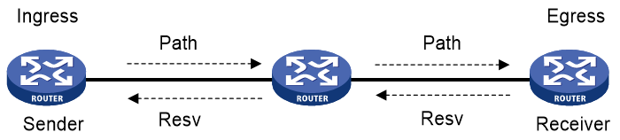
CRLSP setup procedure
As shown in Figure 1, a CRLSP is set up by using the following steps:
1. The ingress LSR generates a Path message that carries LABEL_REQUEST, and then forwards the message along the path calculated by CSPF hop-by-hop towards the egress LSR.
2. After receiving the Path message, the egress LSR generates a Resv message carrying the reservation information and the LABEL object. It forwards the Resv message to the ingress LSR along the reverse direction of the path that the Path message traveled.
The Resv message advertises labels, reserves resources, and creates a reserve state on each LSR it passes, so QoS can be guaranteed for services transmitted on the CRLSP.
3. When the ingress LSR receives the Resv message, the CRLSP is established.
Figure 1 Setting up a CRLSP
RSVP refresh mechanism
Refresh messages
RSVP maintains resource reservation states on a node by periodically sending messages.
The resource reservation states include path states and reservation states. A path state is saved in a path state block (PSB), and a reservation state is saved in a reservation state block (RSB). A PSB is created by a Path message and saves the LABEL_REQUEST object. A RSB is created by a Resv message and saves the LABEL object.
The path states and reservation states are refreshed periodically by Path and Resv messages. A state is removed if no refresh messages for the state are received in a certain interval, and the CRLSP established based on this state is also removed.
The Path and Resv messages for refreshing the resource reservation states are collectively referred to as refresh messages. Refresh messages can also be used to recover from lost RSVP messages.
When multiple RSVP sessions exist on a network, a short refresh interval can cause network degradation, but a long refresh interval cannot meet the requirements of delay sensitive applications. To find an appropriate balance, you can use the summary refresh (Srefresh) and the reliable RSVP message delivery features.
Srefresh
Srefresh is implemented by adding a Message_ID object to a Path or Resv message to uniquely identify the message. To refresh Path and Resv states, RSVP does not need to send standard Path and Resv messages. Instead, it sends an Srefresh message carrying a set of Message_ID objects that identify the Path and Resv states to be refreshed. The Srefresh feature reduces the number of refresh messages on the network and speeds up refresh message processing.
Reliable RSVP message delivery
An RSVP sender cannot know or retransmit lost RSVP messages. The reliable RSVP message delivery mechanism is designed to ensure reliable transmission.
This mechanism requires the peer device to acknowledge each RSVP message received from the local device. If no acknowledgment is received, the local device retransmits the message.
To implement reliable RSVP message delivery, a node sends an RSVP message that includes a Message_ID object in which the ACK_Desired flag is set. The receiver needs to confirm the delivery by sending back a message that includes the Message_ID_ACK object. If the sender does not receive a Message_ID_ACK within the retransmission interval (Rf), it performs the following tasks:
· Retransmits the message when Rf expires.
· Sets the next transmission interval to (1 + delta) × Rf.
The sender repeats this process until it receives the Message_ID_ACK before the retransmission time expires or it has transmitted the message three times.
RSVP authentication
RSVP authentication ensures integrity of RSVP messages, and prevents false resource reservation requests from occupying network resources.
With RSVP authentication, the sender uses the MD5 algorithm and the authentication key to calculate a message digest for an RSVP message, and inserts the digest to the RSVP message. When the receiver receives the message, it performs the same calculation and compares the result with the message digest. If they match, the receiver accepts the message. Otherwise, it drops the message.
By carrying a sequence number in a message, RSVP authentication can also prevent packet replay attacks. The device records the sequence number of a received RSVP message, and determines whether the subsequent messages are valid according to the recorded sequence number. If the sequence number of a subsequent message is within the valid range, the device accepts the message. Otherwise, it drops the message.
RSVP GR
RSVP GR defines the following roles:
· GR restarter—Router that gracefully restarts due to a manually configured command or a fault. It must be GR-capable.
· GR helper—Neighbor of the GR restarter. A GR helper maintains the neighbor relationship with the GR restarter and helps the GR restarter restore its LFIB information. A GR helper must be GR-capable.
The device can act only as a RSVP GR helper.
The RSVP GR feature depends on the extended hello capability of RSVP. A GR-capable device advertises its GR capability and relevant time parameters to its neighbors in RSVP hello packets. If a device and all its neighbors have the RSVP GR capability and have exchanged GR parameters, each of them can function as the GR helper of another device.
A GR helper considers that a GR restarter is rebooting when the number of consecutive lost hellos or erroneous hellos reaches the value configured by the hello lost command. When a GR restarter is rebooting, the GR helpers perform the following operations:
· Retain soft state information about the GR restarter.
· Continue sending hello packets periodically to the GR restarter until the restart timer expires.
If a GR helper receives a hello message from the GR restarter before the restart timer expires, the recovery timer is started and signaling packet exchange is triggered to restore the original soft state. Otherwise, all RSVP soft state information and forwarding entries relevant to the neighbor are removed. When the recovery timer expires, soft state information and forwarding entries that are not restored are removed.
Protocols and standards
· RFC 2205, Resource ReSerVation Protocol
· RFC 3209, RSVP-TE: Extensions to RSVP for LSP Tunnels
· RFC 2961, RSVP Refresh Overhead Reduction Extensions
· RFC 4461, Signaling Requirements for Point-to-Multipoint Traffic-Engineered MPLS Label Switched Paths (LSPs)
· RFC 4875, Extensions to Resource Reservation Protocol - Traffic Engineering (RSVP-TE) for Point-to-Multipoint TE Label Switched Paths (LSPs)
Restrictions: Hardware compatibility with RSVP
|
Hardware |
RSVP compatibility |
|
MSR810, MSR810-W, MSR810-W-DB, MSR810-LM, MSR810-W-LM, MSR810-10-PoE, MSR810-LM-HK, MSR810-W-LM-HK, MSR810-LM-CNDE-SJK, MSR810-CNDE-SJK |
Yes |
|
MSR810-LMS, MSR810-LUS |
No |
|
MSR810-LMS-EA, MSR810-LME |
Yes |
|
MSR2600-6-X1, MSR2600-10-X1 |
Yes |
|
MSR 2630 |
Yes |
|
MSR3600-28, MSR3600-51 |
Yes |
|
MSR3600-28-SI, MSR3600-51-SI |
No |
|
MSR3600-28-X1, MSR3600-28-X1-DP, MSR3600-51-X1, MSR3600-51-X1-DP |
Yes |
|
MSR3610-I-DP, MSR3610-IE-DP, MSR3610-IE-ES, MSR3610-IE-EAD, MSR3610-I-IG, MSR3610-IE-IG |
Yes |
|
MSR3610-X1, MSR3610-X1-DP, MSR3610-X1-DC, MSR3610-X1-DP-DC |
Yes |
|
MSR 3610, MSR 3620, MSR 3620-DP, MSR 3640, MSR 3660 |
Yes |
|
MSR3610-G, MSR3620-G |
Yes |
|
Hardware |
RSVP compatibility |
|
MSR810-W-WiNet, MSR810-LM-WiNet |
Yes |
|
MSR830-4LM-WiNet |
Yes |
|
MSR830-5BEI-WiNet, MSR830-6EI-WiNet, MSR830-10BEI-WiNet |
Yes |
|
MSR830-6BHI-WiNet, MSR830-10BHI-WiNet |
Yes |
|
MSR2600-6-WiNet, MSR2600-10-X1-WiNet |
Yes |
|
MSR2630-WiNet |
Yes |
|
MSR3600-28-WiNet |
Yes |
|
MSR3610-X1-WiNet |
Yes |
|
MSR3610-WiNet, MSR3620-10-WiNet, MSR3620-DP-WiNet, MSR3620-WiNet, MSR3660-WiNet |
Yes |
|
Hardware |
RSVP compatibility |
|
MSR2630-XS |
Yes |
|
MSR3600-28-XS |
Yes |
|
MSR3610-XS |
Yes |
|
MSR3620-XS |
Yes |
|
MSR3610-I-XS |
Yes |
|
MSR3610-IE-XS |
Yes |
|
Hardware |
RSVP compatibility |
|
MSR810-LM-GL |
Yes |
|
MSR810-W-LM-GL |
Yes |
|
MSR830-6EI-GL |
Yes |
|
MSR830-10EI-GL |
Yes |
|
MSR830-6HI-GL |
Yes |
|
MSR830-10HI-GL |
Yes |
|
MSR2600-6-X1-GL |
Yes |
|
MSR3600-28-SI-GL |
No |
RSVP tasks at a glance
To configure RSVP, perform the following tasks:
To establish an MPLS TE tunnel by using RSVP-TE, you must enable RSVP on all nodes and interfaces that the tunnel traverses.
2. (Optional.) Configuring RSVP refresh
3. (Optional.) Configuring RSVP Srefresh
4. (Optional.) Configuring reliable RSVP message delivery
5. (Optional.) Configuring RSVP hello extension
6. (Optional.) Configuring RSVP authentication
7. (Optional.) Setting a DSCP value for outgoing RSVP packets
8. (Optional.) Configuring RSVP GR
9. (Optional.) Enabling BFD for RSVP
Enabling RSVP
About this task
To establish an MPLS TE tunnel by using RSVP-TE, you must enable RSVP on all nodes and interfaces that the tunnel traverses.
Procedure
1. Enter system view.
system-view
2. Enable global RSVP and enter RSVP view.
rsvp
By default, global RSVP is disabled.
3. Return to system view.
quit
4. Enter interface view.
interface interface-type interface-number
5. Enable RSVP on the interface.
rsvp enable
By default, RSVP is disabled on the interface.
Configuring RSVP refresh
6. Enter system view.
system-view
7. Enter RSVP view.
rsvp
8. Set the refresh interval for Path and Resv messages.
refresh interval interval
By default, the refresh interval is 30 seconds for both path and Resv messages.
9. Set the PSB and RSB timeout multiplier.
keep-multiplier number
By default, the PSB and RSB timeout multiplier is 3.
Configuring RSVP Srefresh
10. Enter system view.
system-view
11. Enter interface view.
interface interface-type interface-number
12. Enable RSVP Srefresh.
rsvp reduction srefresh
By default, RSVP Srefresh is disabled.
After RSVP Srefresh is enabled, RSVP maintains the path and reservation states by sending Srefresh messages rather than standard refresh messages.
Configuring reliable RSVP message delivery
13. Enter system view.
system-view
14. Enter interface view.
interface interface-type interface-number
15. Enable reliable RSVP message delivery.
rsvp reduction srefresh reliability
By default, Srefresh and reliable RSVP message delivery are disabled.
16. (Optional.) Set the retransmission parameters for reliable RSVP message delivery.
¡ Set the retransmission increment value for reliable RSVP message delivery.
rsvp reduction retransmit increment increment-value
By default, the RSVP message retransmission increment is 1.
¡ Set the retransmission interval for reliable RSVP message delivery.
rsvp reduction retransmit interval interval
By default, the RSVP message retransmission interval is 500 milliseconds.
The actual retransmission interval equals (1 + retransmission increment value ) × retransmission interval.
Configuring RSVP hello extension
About this task
When RSVP hello extension is enabled on an interface, the device receives and sends hello messages through the interface to detect the neighbor's status.
If the device receives a hello request from the neighbor, the device replies with a hello ACK message. If the device receives no hello request from the neighbor within the interval specified by the hello interval command, the device sends hello requests to the neighbor.
When the number of consecutive lost hellos or erroneous hellos from the neighbor reaches the maximum (specified by the hello lost command), the device determines the neighbor is in fault. If GR is configured, the device acts as a GR helper to help the neighbor to restart. If FRR is configured, the device performs an FRR. For more information about FRR, see "Configuring MPLS TE."
Procedure
1. Enter system view.
system-view
2. Enter interface view.
interface interface-type interface-number
3. Enable RSVP hello extension.
rsvp hello enable
By default, RSVP hello extension is disabled.
4. (Optional.) Set RSVP hello extension parameters:
a. Return to system view.
quit
b. Enter RSVP view.
rsvp
c. Set the maximum number of consecutive lost or erroneous hellos.
hello lost times
By default, the maximum number is 4.
d. Set the interval for sending hello requests.
hello interval interval
By default, hello requests are sent every 5 seconds.
Configuring RSVP authentication
About RSVP authentication
RSVP adopts hop-by-hop authentication to prevent fake resource reservation requests from occupying network resources. The interfaces at the two ends of a link must use the same authentication key.
Restrictions and guidelines for RSVP authentication
Do not enable both RSVP authentication and FRR on the same interface. Otherwise, the authentication might fail.
RSVP authentication can be configured in the following views:
· RSVP view—Configuration applies to all RSVP security associations.
· RSVP neighbor view—Configuration applies only to RSVP security associations with the specified RSVP neighbor.
· Interface view—Configuration applies only to RSVP security associations established on the current interface.
Configurations in RSVP neighbor view, interface view, and RSVP view are in descending order of priority.
Configuring RSVP authentication (RSVP neighbor view)
1. Enter system view.
system-view
2. Enter RSVP view.
rsvp
3. Create an RSVP authentication neighbor and enter RSVP neighbor view.
peer ip-address
4. Enable RSVP authentication for the RSVP neighbor and specify the authentication key.
authentication key { cipher | plain } string
By default, RSVP authentication is disabled.
5. (Optional.) Enable challenge-response handshake for the RSVP neighbor.
authentication challenge
By default, the challenge-response handshake feature is disabled.
6. (Optional.) Set the idle timeout for the RSVP security associations with the RSVP neighbor.
authentication lifetime life-time
By default, the idle timeout is 1800 seconds (30 minutes).
7. (Optional.) Set the maximum number of out-of-sequence RSVP authentication messages that can be received from the RSVP neighbor.
authentication window-size number
By default, only one RSVP authenticated message can be received out of sequence.
Configuring RSVP authentication (interface view)
1. Enter system view.
system-view
2. Enter interface view.
interface interface-type interface-number
3. Enable RSVP authentication on the interface and configure the authentication key.
rsvp authentication key { cipher | plain } string
By default, RSVP authentication is disabled.
4. (Optional.) Enable challenge-response handshake on the interface.
rsvp authentication challenge
By default, the challenge-response handshake feature is disabled.
5. (Optional.) Set the idle timeout for RSVP security associations on the interface.
rsvp authentication lifetime life-time
By default, the idle timeout is 1800 seconds (30 minutes).
6. (Optional.) Set the maximum number of out-of-sequence RSVP authentication messages that can be received on the interface.
rsvp authentication window-size number
By default, only one RSVP authenticated message can be received out of sequence.
Configuring RSVP authentication (RSVP view)
1. Enter system view.
system-view
2. Enter RSVP view.
rsvp
3. Enable RSVP authentication globally and configure the authentication key.
authentication key { cipher | plain } string
By default, RSVP authentication is disabled.
4. (Optional.) Enable challenge-response handshake globally.
authentication challenge
By default, the challenge-response handshake feature is disabled.
5. (Optional.) Set the global idle timeout for RSVP security associations.
authentication lifetime life-time
By default, the idle timeout is 1800 seconds (30 minutes).
6. (Optional.) Set the global RSVP authentication window size (the maximum number of RSVP authenticated messages that can be received out of sequence).
authentication window-size number
By default, only one RSVP authenticated message can be received out of sequence.
Setting a DSCP value for outgoing RSVP packets
About this task
The DSCP value of an IP packet specifies the priority level of the packet and affects the transmission priority of the packet.
Procedure
1. Enter system view.
system-view
2. Enter RSVP view.
rsvp
3. Set a DSCP value for outgoing RSVP packets.
dscp dscp-value
By default, the DSCP value is 48.
Configuring RSVP GR
Prerequisites
RSVP GR depends on the RSVP hello extension feature. When configuring RSVP GR, you must enable RSVP hello extension.
Procedure
1. Enter system view.
system-view
2. Enter RSVP view.
rsvp
3. Enable GR for RSVP.
graceful-restart enable
By default, RSVP GR is disabled.
Enabling BFD for RSVP
About this task
If a link fails, MPLS TE tunnels over the link fail to forward packets. MPLS TE cannot quickly detect a link failure. To address this issue, you can enable BFD for RSVP so MPLS TE can quickly switch data from the primary path to the backup path upon a link failure.
Procedure
1. Enter system view.
system-view
2. Enter interface view.
interface interface-type interface-number
You must enable RSVP on the interface.
3. Enable BFD for the RSVP neighbor on the interface.
rsvp bfd enable
By default, RSVP BFD is disabled.
Display and maintenance commands for RSVP
Execute display commands in any view and reset commands in user view.
|
Task |
Command |
|
Display RSVP information. |
display rsvp [ interface [ interface-type interface-number ] ] |
|
Display information about the security associations established with RSVP neighbors. |
display rsvp authentication [ from ip-address ] [ to ip-address ] [ verbose ] |
|
Display information about CRLSPs established through RSVP. |
display rsvp lsp [ destination ip-address ] [ source ip-address ] [ tunnel-id tunnel-id ] [ lsp-id lsp-id ] [ verbose ] |
|
Display information about RSVP neighbors. |
display rsvp peer [ interface interface-type interface-number ] [ ip ip-address ] [ verbose ] |
|
Display information about RSVP resource reservation requests sent to upstream devices. |
display rsvp request [ destination ip-address ] [ source ip-address ] [ tunnel-id tunnel-id ] [ prevhop ip-address ] [ verbose ] |
|
Display information about RSVP resource reservation states. |
display rsvp reservation [ destination ip-address ] [ source ip-address ] [ tunnel-id tunnel-id ] [ nexthop ip-address ] [ verbose ] |
|
Display information about RSVP path states. |
display rsvp sender [ destination ip-address ] [ source ip-address ] [ tunnel-id tunnel-id ] [ lsp-id lsp-id ] [ verbose ] |
|
Display RSVP statistics. |
display rsvp statistics [ interface [ interface-type interface-number ] ] |
|
Clear RSVP security associations. |
reset rsvp authentication [ from ip-address to ip-address ] |
|
Clear RSVP statistics. |
reset rsvp statistics [ interface [ interface-type interface-number ] |
RSVP configuration examples
Example: Establishing an MPLS TE tunnel with RSVP-TE
Network configuration
Router A, Router B, Router C, and Router D run IS-IS and all of them are Layer 2 routers.
Use RSVP-TE to establish an MPLS TE tunnel from Router A to Router D to transmit data between the two IP networks. The MPLS TE tunnel requires a bandwidth of 2000 kbps.
The maximum bandwidth of the link that the tunnel traverses is 10000 kbps and the maximum reservable bandwidth of the link is 5000 kbps.
Figure 2 Network diagram
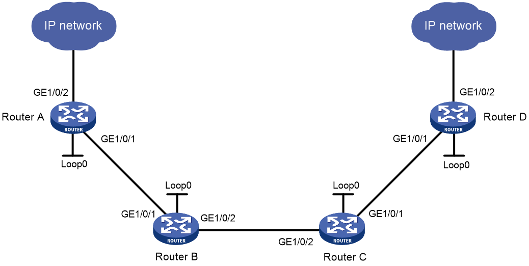
Table 1 Interface and IP address assignment
|
Interface |
IP address |
Device |
Interface |
IP address |
|
|
Router A |
Loop0 |
1.1.1.9/32 |
Router C |
Loop0 |
3.3.3.9/32 |
|
|
GE1/0/1 |
10.1.1.1/24 |
|
GE1/0/1 |
30.1.1.1/24 |
|
|
GE1/0/2 |
100.1.1.1/24 |
|
GE1/0/2 |
20.1.1.2/24 |
|
Router B |
Loop0 |
2.2.2.9/32 |
Router D |
Loop0 |
4.4.4.9/32 |
|
|
GE1/0/1 |
10.1.1.2/24 |
|
GE1/0/1 |
30.1.1.2/24 |
|
|
GE1/0/2 |
20.1.1.1/24 |
|
GE1/0/2 |
100.1.2.1/24 |
Procedure
1. Configure IP addresses and masks for interfaces. (Details not shown.)
2. Configure IS-IS to advertise interface addresses, including the loopback interface address:
# Configure Router A.
<RouterA> system-view
[RouterA] isis 1
[RouterA-isis-1] network-entity 00.0005.0000.0000.0001.00
[RouterA-isis-1] quit
[RouterA] interface gigabitethernet 1/0/1
[RouterA-GigabitEthernet1/0/1] isis enable 1
[RouterA-GigabitEthernet1/0/1] isis circuit-level level-2
[RouterA-GigabitEthernet1/0/1] quit
[RouterA] interface loopback 0
[RouterA-LoopBack0] isis enable 1
[RouterA-LoopBack0] isis circuit-level level-2
[RouterA-LoopBack0] quit
# Configure Router B.
<RouterB> system-view
[RouterB] isis 1
[RouterB-isis-1] network-entity 00.0005.0000.0000.0002.00
[RouterB-isis-1] quit
[RouterB] interface gigabitethernet 1/0/1
[RouterB-GigabitEthernet1/0/1] isis enable 1
[RouterB-GigabitEthernet1/0/1] isis circuit-level level-2
[RouterB-GigabitEthernet1/0/1] quit
[RouterB] interface gigabitethernet 1/0/2
[RouterB-GigabitEthernet1/0/2] isis enable 1
[RouterB-GigabitEthernet1/0/2] isis circuit-level level-2
[RouterB-GigabitEthernet1/0/2] quit
[RouterB] interface loopback 0
[RouterB-LoopBack0] isis enable 1
[RouterB-LoopBack0] isis circuit-level level-2
[RouterB-LoopBack0] quit
# Configure Router C.
<RouterC> system-view
[RouterC] isis 1
[RouterC-isis-1] network-entity 00.0005.0000.0000.0003.00
[RouterC-isis-1] quit
[RouterC] interface gigabitethernet 1/0/1
[RouterC-GigabitEthernet1/0/1] isis enable 1
[RouterC-GigabitEthernet1/0/1] isis circuit-level level-2
[RouterC-GigabitEthernet1/0/1] quit
[RouterC] interface gigabitethernet 1/0/2
[RouterC-GigabitEthernet1/0/2] isis enable 1
[RouterC-GigabitEthernet1/0/2] isis circuit-level level-2
[RouterC-GigabitEthernet1/0/2] quit
[RouterC] interface loopback 0
[RouterC-LoopBack0] isis enable 1
[RouterC-LoopBack0] isis circuit-level level-2
[RouterC-LoopBack0] quit
# Configure Router D.
<RouterD> system-view
[RouterD] isis 1
[RouterD-isis-1] network-entity 00.0005.0000.0000.0004.00
[RouterD-isis-1] quit
[RouterD] interface gigabitethernet 1/0/1
[RouterD-GigabitEthernet1/0/1] isis enable 1
[RouterD-GigabitEthernet1/0/1] isis circuit-level level-2
[RouterD-GigabitEthernet1/0/1] quit
[RouterD] interface loopback 0
[RouterD-LoopBack0] isis enable 1
[RouterD-LoopBack0] isis circuit-level level-2
[RouterD-LoopBack0] quit
# Execute the display ip routing-table command on each router to verify that the routers have learned the routes to one another, including the routes to the loopback interfaces. (Details not shown.)
3. Configure an LSR ID, and enable MPLS, MPLS TE, and RSVP:
# Configure Router A.
[RouterA] mpls lsr-id 1.1.1.9
[RouterA] mpls te
[RouterA-te] quit
[RouterA] rsvp
[RouterA-rsvp] quit
[RouterA] interface gigabitethernet 1/0/1
[RouterA-GigabitEthernet1/0/1] mpls enable
[RouterA-GigabitEthernet1/0/1] mpls te enable
[RouterA-GigabitEthernet1/0/1] rsvp enable
[RouterA-GigabitEthernet1/0/1] quit
# Configure Router B.
[RouterB] mpls lsr-id 2.2.2.9
[RouterB] mpls te
[RouterB-te] quit
[RouterB] rsvp
[RouterB-rsvp] quit
[RouterB] interface gigabitethernet 1/0/1
[RouterB-GigabitEthernet1/0/1] mpls enable
[RouterB-GigabitEthernet1/0/1] mpls te enable
[RouterB-GigabitEthernet1/0/1] rsvp enable
[RouterB-GigabitEthernet1/0/1] quit
[RouterB] interface gigabitethernet 1/0/2
[RouterB-GigabitEthernet1/0/2] mpls enable
[RouterB-GigabitEthernet1/0/2] mpls te enable
[RouterB-GigabitEthernet1/0/2] rsvp enable
[RouterB-GigabitEthernet1/0/2] quit
# Configure Router C.
[RouterC] mpls lsr-id 3.3.3.9
[RouterC] mpls te
[RouterC-te] quit
[RouterC] rsvp
[RouterC-rsvp] quit
[RouterC] interface gigabitethernet 1/0/1
[RouterC-GigabitEthernet1/0/1] mpls enable
[RouterC-GigabitEthernet1/0/1] mpls te enable
[RouterC-GigabitEthernet1/0/1] rsvp enable
[RouterC-GigabitEthernet1/0/1] quit
[RouterC] interface gigabitethernet 1/0/2
[RouterC-GigabitEthernet1/0/2] mpls enable
[RouterC-GigabitEthernet1/0/2] mpls te enable
[RouterC-GigabitEthernet1/0/2] rsvp enable
[RouterC-GigabitEthernet1/0/2] quit
# Configure Router D.
[RouterD] mpls lsr-id 4.4.4.9
[RouterD] mpls te
[RouterD-te] quit
[RouterD] rsvp
[RouterD-rsvp] quit
[RouterD] interface gigabitethernet 1/0/1
[RouterD-GigabitEthernet1/0/1] mpls enable
[RouterD-GigabitEthernet1/0/1] mpls te enable
[RouterD-GigabitEthernet1/0/1] rsvp enable
[RouterD-GigabitEthernet1/0/1] quit
4. Configure IS-IS TE:
# Configure Router A.
[RouterA] isis 1
[RouterA-isis-1] cost-style wide
[RouterA-isis-1] mpls te enable level-2
[RouterA-isis-1] quit
# Configure Router B.
[RouterB] isis 1
[RouterB-isis-1] cost-style wide
[RouterB-isis-1] mpls te enable level-2
[RouterB-isis-1] quit
# Configure Router C.
[RouterC] isis 1
[RouterC-isis-1] cost-style wide
[RouterC-isis-1] mpls te enable level-2
[RouterC-isis-1] quit
# Configure Router D.
[RouterD] isis 1
[RouterD-isis-1] cost-style wide
[RouterD-isis-1] mpls te enable level-2
[RouterD-isis-1] quit
5. Configure MPLS TE attributes of links:
# Set the maximum link bandwidth and maximum reservable bandwidth on Router A.
[RouterA] interface gigabitethernet 1/0/1
[RouterA-GigabitEthernet1/0/1] mpls te max-link-bandwidth 10000
[RouterA-GigabitEthernet1/0/1] mpls te max-reservable-bandwidth 5000
[RouterA-GigabitEthernet1/0/1] quit
# Set the maximum link bandwidth and maximum reservable bandwidth on Router B.
[RouterB] interface gigabitethernet 1/0/1
[RouterB-GigabitEthernet1/0/1] mpls te max-link-bandwidth 10000
[RouterB-GigabitEthernet1/0/1] mpls te max-reservable-bandwidth 5000
[RouterB-GigabitEthernet1/0/1] quit
[RouterB] interface gigabitethernet 1/0/2
[RouterB-GigabitEthernet1/0/2] mpls te max-link-bandwidth 10000
[RouterB-GigabitEthernet1/0/2] mpls te max-reservable-bandwidth 5000
[RouterB-GigabitEthernet1/0/2] quit
# Set the maximum link bandwidth and maximum reservable bandwidth on Router C.
[RouterC] interface gigabitethernet 1/0/1
[RouterC-GigabitEthernet1/0/1] mpls te max-link-bandwidth 10000
[RouterC-GigabitEthernet1/0/1] mpls te max-reservable-bandwidth 5000
[RouterC-GigabitEthernet1/0/1] quit
[RouterC] interface gigabitethernet 1/0/2
[RouterC-GigabitEthernet1/0/2] mpls te max-link-bandwidth 10000
[RouterC-GigabitEthernet1/0/2] mpls te max-reservable-bandwidth 5000
[RouterC-GigabitEthernet1/0/2] quit
# Set the maximum link bandwidth and maximum reservable bandwidth on Router D.
[RouterD] interface gigabitethernet 1/0/1
[RouterD-GigabitEthernet1/0/1] mpls te max-link-bandwidth 10000
[RouterD-GigabitEthernet1/0/1] mpls te max-reservable-bandwidth 5000
[RouterD-GigabitEthernet1/0/1] quit
6. Configure an MPLS TE tunnel on Router A:
# Configure MPLS TE tunnel interface Tunnel 1.
[RouterA] interface tunnel 1 mode mpls-te
[RouterA-Tunnel1] ip address 7.1.1.1 255.255.255.0
# Specify the tunnel destination address as the LSR ID of Router D.
[RouterA-Tunnel1] destination 4.4.4.9
# Configure MPLS TE to use RSVP-TE to establish the tunnel.
[RouterA-Tunnel1] mpls te signaling rsvp-te
# Assign 2000 kbps bandwidth to the tunnel.
[RouterA-Tunnel1] mpls te bandwidth 2000
[RouterA-Tunnel1] quit
7. Configure a static route on Router A to direct the traffic destined for subnet 100.1.2.0/24 to MPLS TE tunnel 1.
[RouterA] ip route-static 100.1.2.0 24 tunnel 1 preference 1
Verifying the configuration
# Verify that the tunnel interface is up on Router A.
[RouterA] display interface tunnel
Tunnel1
Current state: UP
Line protocol state: UP
Description: Tunnel1 Interface
Bandwidth: 64kbps
Maximum transmission unit: 64000
Internet address: 7.1.1.1/24 (primary)
Tunnel source unknown, destination 4.4.4.9
Tunnel TTL 255
Tunnel protocol/transport CR_LSP
Output queue - Urgent queuing: Size/Length/Discards 0/100/0
Output queue - Protocol queuing: Size/Length/Discards 0/500/0
Output queue - FIFO queuing: Size/Length/Discards 0/75/0
Last clearing of counters: Never
Last 300 seconds input rate: 0 bytes/sec, 0 bits/sec, 0 packets/sec
Last 300 seconds output rate: 0 bytes/sec, 0 bits/sec, 0 packets/sec
Input: 0 packets, 0 bytes, 0 drops
Output: 0 packets, 0 bytes, 0 drops
# Display detailed information about the MPLS TE tunnel on Router A.
[RouterA] display mpls te tunnel-interface
Tunnel Name : Tunnel 1
Tunnel State : Up (Main CRLSP up, Shared-resource CRLSP down)
Tunnel Attributes :
LSP ID : 23331 Tunnel ID : 1
Admin State : Normal
Ingress LSR ID : 1.1.1.9 Egress LSR ID : 4.4.4.9
Signaling : RSVP-TE Static CRLSP Name : -
Resv Style : SE
Tunnel mode : -
Reverse-LSP name : -
Reverse-LSP LSR ID : - Reverse-LSP Tunnel ID: -
Class Type : CT0 Tunnel Bandwidth : 2000 kbps
Reserved Bandwidth : 2000 kbps
Setup Priority : 7 Holding Priority : 7
Affinity Attr/Mask : 0/0
Explicit Path : -
Backup Explicit Path : -
Metric Type : TE
Record Route : Disabled Record Label : Disabled
FRR Flag : Disabled Backup Bandwidth Flag: Disabled
Backup Bandwidth Type: - Backup Bandwidth : -
Route Pinning : Disabled
Retry Limit : 10 Retry Interval : 2 sec
Reoptimization : Disabled Reoptimization Freq : -
Backup Type : None Backup LSP ID : -
Auto Bandwidth : Disabled Auto Bandwidth Freq : -
Min Bandwidth : - Max Bandwidth : -
Collected Bandwidth : - Service-Class : -
# Execute the display ip routing-table command on Router A to verify that a static route entry with interface Tunnel 1 as the output interface exists. (Details not shown.)
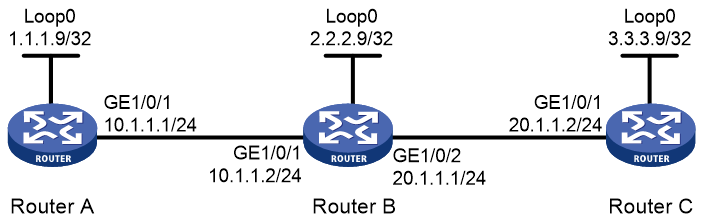
Example: Configuring RSVP GR
Network configuration
Router A, Router B, and Router C run IS-IS, and all of them are Layer 2 devices.
Use RSVP-TE to establish a TE tunnel from Router A to Router C.
Configure RSVP GR on the routers to ensure continuous forwarding when a router reboots.
Figure 3 Network diagram
Procedure
1. Configure IP addresses and masks for interfaces. (Details not shown.)
2. Configure IS-IS to advertise interface addresses, including the loopback interface address. (Details not shown.)
3. Configure an LSR ID, enable MPLS, MPLS TE, RSVP, and RSVP hello extension:
# Configure Router A.
<RouterA> system-view
[RouterA] mpls lsr-id 1.1.1.9
[RouterA] mpls te
[RouterA-te] quit
[RouterA] rsvp
[RouterA-rsvp] quit
[RouterA] interface gigabitethernet 1/0/1
[RouterA-GigabitEthernet1/0/1] mpls enable
[RouterA-GigabitEthernet1/0/1] mpls te enable
[RouterA-GigabitEthernet1/0/1] rsvp enable
[RouterA-GigabitEthernet1/0/1] rsvp hello enable
[RouterA-GigabitEthernet1/0/1] quit
# Configure Router B.
<RouterB> system-view
[RouterB] mpls lsr-id 2.2.2.9
[RouterB] mpls te
[RouterB-te] quit
[RouterB] rsvp
[RouterB] quit
[RouterB] interface gigabitethernet 1/0/1
[RouterB-GigabitEthernet1/0/1] mpls enable
[RouterB-GigabitEthernet1/0/1] mpls te enable
[RouterB-GigabitEthernet1/0/1] rsvp enable
[RouterB-GigabitEthernet1/0/1] rsvp hello enable
[RouterB-GigabitEthernet1/0/1] quit
[RouterB] interface gigabitethernet 1/0/2
[RouterB-GigabitEthernet1/0/2] mpls enable
[RouterB-GigabitEthernet1/0/2] mpls te enable
[RouterB-GigabitEthernet1/0/2] rsvp enable
[RouterB-GigabitEthernet1/0/2] rsvp hello enable
[RouterB-GigabitEthernet1/0/2] quit
# Configure Router C.
<RouterC> system-view
[RouterC] mpls lsr-id 3.3.3.9
[RouterC] mpls te
[RouterC-te] quit
[RouterC] rsvp
[RouterC-rsvp] rsvp
[RouterC-mpls] interface gigabitethernet 1/0/1
[RouterC-GigabitEthernet1/0/1] mpls enable
[RouterC-GigabitEthernet1/0/1] mpls te enable
[RouterC-GigabitEthernet1/0/1] rsvp enable
[RouterC-GigabitEthernet1/0/1] rsvp hello enable
[RouterC-GigabitEthernet1/0/1] quit
4. Configure IS-IS TE. (Details not shown.)
5. Configure an MPLS TE tunnel. (Details not shown.)
6. Configure RSVP GR:
# Configure Router A.
[RouterA] rsvp
[RouterA-rsvp] graceful-restart enable
# Configure Router B.
[RouterB] rsvp
[RouterB-rsvp] graceful-restart enable
# Configure Router C.
[RouterC] rsvp
[RouterC-rsvp] graceful-restart enable
Verifying the configuration
After a tunnel is established from Router A to Router C, display detailed RSVP neighbor information on Router A.
<RouterA> display rsvp peer verbose
Peer: 10.1.1.2 Interface: GE1/0/1
Hello state: Up Hello type: Active
PSB count: 0 RSB count: 1
Src instance: 0x1f08 Dst instance: 0x22
Summary refresh: Disabled Graceful Restart state: Ready
Peer GR restart time: 120000 ms Peer GR recovery time: 0 ms
The output shows that the neighbor's GR state is Ready.
