- Table of Contents
-
- 10-MPLS Configuration Guide
- 00-Preface
- 01-Basic MPLS configuration
- 02-Static LSP configuration
- 03-LDP configuration
- 04-MPLS TE configuration
- 05-Static CRLSP configuration
- 06-RSVP configuration
- 07-Tunnel policy configuration
- 08-MPLS L3VPN configuration
- 09-MPLS L2VPN configuration
- 10-VPLS configuration
- 11-L2VPN access to L3VPN or IP backbone configuration
- 12-MPLS OAM configuration
- 13-MPLS protection switching configuration
- 14-MCE configuration
- Related Documents
-
| Title | Size | Download |
|---|---|---|
| 03-LDP configuration | 808.97 KB |
Label distribution and control
Restrictions: Hardware compatibility with LDP
Restrictions and guidelines for enabling LDP
Restrictions and guidelines for hello parameter configuration
Setting Targeted Hello timers for an LDP peer
Configuring LDP session parameters
Restrictions and guidelines for configuring LDP session parameters
Configuring LDP sessions parameters for Basic Discovery mechanism
Configuring LDP IPv4 sessions parameters for Extended Discovery mechanism
Configuring LDP IPv6 sessions parameters for Extended Discovery mechanism
Setting a DSCP value for outgoing LDP packets
Configuring LDP to redistribute BGP unicast routes
Configuring an LSP generation policy
Configuring the LDP label distribution control mode
Configuring a label advertisement policy
Configuring a label acceptance policy
Configuring LDP MD5 authentication
Configuring LDP loop detection
Configuring LDP session protection
Configuring LDP-route synchronization
Restrictions and guidelines for LDP-route synchronization
Configuring LDP-static route synchronization
Configuring LDP-OSPF synchronization
Configuring LDP IS-IS synchronization
Configuring LDP remote LFA FRR
Enabling SNMP notifications for LDP
Display and maintenance commands for LDP
IPv4 LDP configuration examples
Example: Configuring label acceptance control
Example: Configuring label advertisement control
IPv6 LDP configuration examples
Example: Configuring IPv6 LDP LSP
Example: Configuring IPv6 label acceptance control
Example: Configuring IPv6 label advertisement control
Restrictions: Hardware compatibility with mLDP
Display and maintenance commands for mLDP P2MP
Configuring LDP
About LDP
The Label Distribution Protocol (LDP) dynamically distributes FEC-label mapping information between LSRs to establish LSPs.
Terminology
LDP session
Two LSRs establish a TCP-based LDP session to exchange FEC-label mappings.
LDP peer
Two LSRs that use LDP to exchange FEC-label mappings are LSR peers.
Label spaces and LDP identifiers
Label spaces include the following types:
· Per-interface label space—Each interface uses a single, independent label space. Different interfaces can use the same label values.
· Per-platform label space—Each LSR uses a single label space. The device only supports the per-platform label space.
A six-byte LDP Identifier (LDP ID) identifies a label space on an LSR. It is in the format of <LSR ID>:<label space number>, where:
· The LSR ID takes four bytes to identity the LSR.
· The label space number takes two bytes to identify a label space within the LSR.
A label space number of 0 indicates that the label space is a per-platform label space. A label space number other than 0 indicates a per-interface label space.
LDP uses the same LDP ID format on IPv4 and IPv6 networks. An LDP ID must be globally unique.
FECs and FEC-label mappings
MPLS groups packets with the same characteristics (such as the same destination or service class) into a class, called an FEC. The packets of the same FEC are handled in the same way on an MPLS network.
LDP can classify FECs by destination IP address and by PW. This document describes FEC classification by destination IP address. For information about FEC classification by PW, see "Configuring MPLS L2VPN" and "Configuring VPLS."
An LSR assigns a label for an FEC and advertises the FEC-label mapping, or FEC-label binding, to its peers in a Label Mapping message.
LDP messages
LDP mainly uses the following types of messages:
· Discovery messages—Declare and maintain the presence of LSRs, such as Hello messages.
· Session messages—Establish, maintain, and terminate sessions between LDP peers, such as Initialization messages used for parameter negotiation and Keepalive messages used to maintain sessions.
· Advertisement messages—Create, alter, and remove FEC-label mappings, such as Label Mapping messages used to advertise FEC-label mappings.
· Notification messages—Provide advisory information and notify errors, such as Notification messages.
LDP uses UDP to transport discovery messages for efficiency, and uses TCP to transport session, advertisement, and notification messages for reliability.
LDP operation
LDP can operate on an IPv4 or IPv6 network, or a network where IPv4 coexists with IPv6. LDP operates similarly on IPv4 and IPv6 networks.
LDP operates in the following phases: discovering and maintaining LDP peers, establishing and maintaining LDP sessions, and establishing LSPs.
Discovering and maintaining LDP peers
LDP discovers peers in the following ways:
· Basic Discovery—Discovers directly connected LSRs.
¡ On an IPv4 network, an LSR sends IPv4 Link Hello messages to multicast address 224.0.0.2. All directly connected LSRs can discover the LSR and establish an IPv4 Link Hello adjacency.
¡ On an IPv6 network, an LSR sends IPv6 Link Hello messages to FF02:0:0:0:0:0:0:2. All directly connected LSRs can discover the LSR and establish an IPv6 Link Hello adjacency.
¡ On a network where IPv4 and IPv6 coexist, an LSR sends both IPv4 and IPv6 Link Hello messages to each directly connected LSR and keeps both the IPv4 and IPv6 Link Hello adjacencies with a neighbor.
· Extended Discovery—Sends LDP IPv4 Targeted Hello messages to an IPv4 address or LDP IPv6 Targeted Hello messages to an IPv6 address. The destination LSR can discover the LSR and establish a hello adjacency. This mechanism is typically used in LDP session protection, LDP over MPLS TE, MPLS L2VPN, and VPLS. For more information about MPLS L2VPN and VPLS, see "Configuring MPLS L2VPN," and "Configuring VPLS."
LDP can establish two hello adjacencies with a directly connected neighbor through both discovery mechanisms. It sends Hello messages at the hello interval to maintain a hello adjacency. If LDP receives no Hello message from a hello adjacency before the hello hold timer expires, it removes the hello adjacency.
Establishing and maintaining LDP sessions
LDP establishes a session to a peer in the following steps:
1. Establishes a TCP connection to the neighbor.
On a network where IPv4 and IPv6 coexist, LDP establishes an IPv6 TCP connection. If LDP fails to establish the IPv6 TCP connection, LDP tries to establish an IPv4 TCP connection.
2. Negotiates session parameters such as LDP version, label distribution method, and Keepalive timer, and establishes an LDP session to the neighbor if the negotiation succeeds.
After a session is established, LDP sends LDP PDUs (an LDP PDU carries one or more LDP messages) to maintain the session. If no information is exchanged between the LDP peers within the Keepalive interval, LDP sends Keepalive messages at the Keepalive interval to maintain the session. If LDP receives no LDP PDU from a neighbor before the keepalive hold timer expires, or the last hello adjacency with the neighbor is removed, LDP terminates the session.
LDP can also send a Shutdown message to a neighbor to terminate the LDP session.
An LSR can establish only one LDP session to a neighbor. The session can be used to exchange IPv4 and IPv6 FEC-label mappings at the same time.
Establishing LSPs
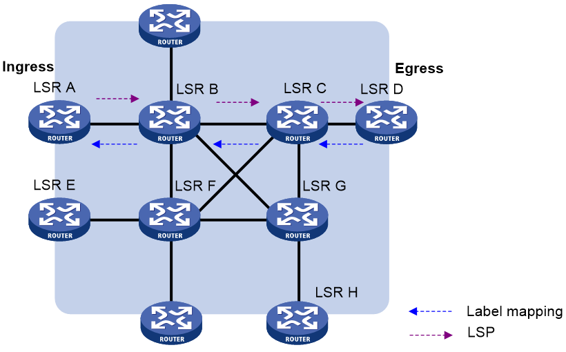
LDP classifies FECs according to destination IP addresses in IP routing entries, creates FEC-label mappings, and advertises the mappings to LDP peers through LDP sessions. After an LDP peer receives an FEC-label mapping, it uses the received label and the label locally assigned to that FEC to create an LFIB entry for that FEC. When all LSRs (from the Ingress to the Egress) establish an LFIB entry for the FEC, an LSP is established exclusively for the FEC.
Figure 1 Dynamically establishing an LSP
Label distribution and control
Label advertisement modes
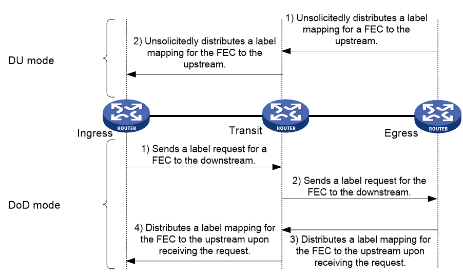
LDP advertises label-FEC mappings in one of the following ways:
· Downstream Unsolicited (DU) mode—Distributes FEC-label mappings to the upstream LSR, without waiting for label requests. The device supports only the DU mode.
· Downstream on Demand (DoD) mode—Sends a label request for an FEC to the downstream LSR. After receiving the label request, the downstream LSR distributes the FEC-label mapping for that FEC to the upstream LSR.
Figure 2 Label advertisement modes
|
|
NOTE: To successfully establish an LSP, a pair of upstream and downstream LSRs must use the same label advertisement mode. |
Label distribution control
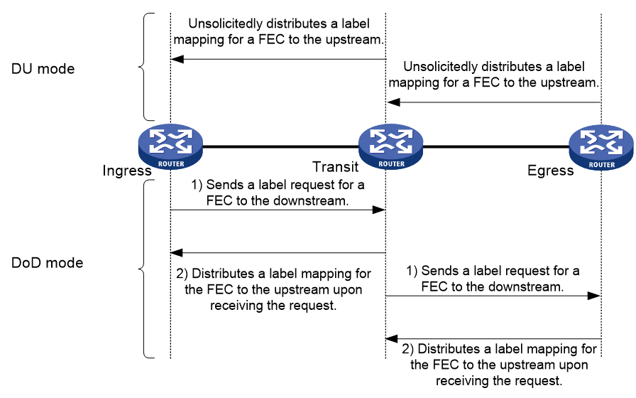
LDP controls label distribution in one of the following ways:
· Independent label distribution—Distributes an FEC-label mapping to an upstream LSR at any time. An LSR might distribute a mapping for an FEC to its upstream LSR before it receives a label mapping for that FEC from its downstream LSR. As shown in Figure 3, in DU mode, each LSR distributes a label mapping for an FEC to its upstream LSR whenever it is ready to label-switch the FEC. The LSRs do not need to wait for a label mapping for the FEC from its downstream LSR. In DoD mode, an LSR distributes a label mapping for an FEC to its upstream LSR after it receives a label request for the FEC. The LSR does not need to wait for a label mapping for the FEC from its downstream LSR.
Figure 3 Independent label distribution control mode
· Ordered label distribution—Distributes a label mapping for an FEC to its upstream LSR only after it receives a label mapping for that FEC from its downstream LSR unless the local node is the egress node of the FEC. As shown in Figure 2, in DU mode, an LSR distributes a label mapping for an FEC to its upstream LSR only if it receives a label mapping for the FEC from its downstream LSR. In DoD mode, when an LSR (Transit) receives a label request for an FEC from its upstream LSR (Ingress), it continues to send a label request for the FEC to its downstream LSR (Egress). After the transit LSR receives a label mapping for the FEC from the egress LSR, it distributes a label mapping for the FEC to the ingress LSR.
Label retention mode
The label retention mode specifies whether an LSR maintains a label mapping for an FEC learned from a neighbor that is not its next hop.
· Liberal label retention—Retains a received label mapping for an FEC regardless of whether the advertising LSR is the next hop of the FEC. This mechanism allows for quicker adaptation to topology changes, but it wastes system resources because LDP has to keep useless labels. The device only supports liberal label retention.
· Conservative label retention—Retains a received label mapping for an FEC only when the advertising LSR is the next hop of the FEC. This mechanism saves label resources, but it cannot quickly adapt to topology changes.
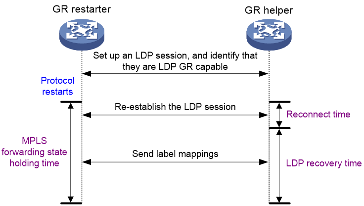
LDP GR
LDP Graceful Restart (GR) preserves label forwarding information when the signaling protocol or control plane fails, so that LSRs can still forward packets according to forwarding entries.
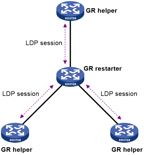
As shown in Figure 4, GR defines the following roles:
· GR restarter—An LSR that performs GR. It must be GR-capable.
· GR helper—A neighbor LSR that helps the GR restarter to complete GR.
The device can act as a GR restarter or a GR helper.
As shown in Figure 5, LDP GR operates as follows:
1. LSRs establish an LDP session. The L flag of the Fault Tolerance TLV in their Initialization messages is set to 1 to indicate that they support LDP GR.
2. When LDP restarts, the GR restarter starts the MPLS Forwarding State Holding timer, and marks the MPLS forwarding entries as stale. When the GR helper detects that the LDP session to the GR restarter goes down, it performs the following operations:
a. Marks the FEC-label mappings learned from the session as stale.
b. Starts the Reconnect timer received from the GR restarter.
3. After LDP completes restart, the GR restarter re-establishes an LDP session to the GR helper.
¡ If the LDP session is not set up before the Reconnect timer expires, the GR helper deletes the stale FEC-label mappings and the corresponding MPLS forwarding entries.
¡ If the LDP session is successfully set up before the Reconnect timer expires, the GR restarter sends the remaining time of the MPLS Forwarding State Holding timer to the GR helper.
The remaining time is sent as the LDP Recovery time.
4. After the LDP session is re-established, the GR helper starts the LDP Recovery timer.
5. The GR restarter and the GR helper exchange label mappings and update their MPLS forwarding tables.
The GR restarter compares each received label mapping against stale MPLS forwarding entries. If a match is found, the restarter deletes the stale mark for the matching entry. Otherwise, it adds a new entry for the label mapping.
The GR helper compares each received label mapping against stale FEC-label mappings. If a match is found, the helper deletes the stale mark for the matching mapping. Otherwise, it adds the received FEC-label mapping and a new MPLS forwarding entry for the mapping.
6. When the MPLS Forwarding State Holding timer expires, the GR restarter deletes all stale MPLS forwarding entries.
7. When the LDP Recovery timer expires, the GR helper deletes all stale FEC-label mappings.
LDP NSR
To use LDP nonstop routing (NSR), the device must have a minimum of two MPUs.
LDP NSR ensures nonstop services of LDP when LDP has redundant processes on multiple MPUs. In contrast to Graceful Restart, NSR does not require an LDP peer to recover MPLS forwarding information.
LDP NSR backs up protocol states and data (including LDP session and LSP information) from the active process to the standby process. When the LDP active process fails, the standby process becomes active and takes over processing seamlessly. The LDP peers are not notified of the LDP interruption. The LDP session stays in Operational state, and the forwarding is not interrupted.
The LDP active process fails when one of the following situations occurs:
· The active process restarts.
· The MPU where the active process resides fails.
· The LDP process is operating at a different location than the one determined by the process placement feature.
LDP-route synchronization
LDP-static route synchronization
When LDP establishes LSPs based on static routes, if LDP and the static routes are not synchronized, MPLS traffic forwarding might be interrupted.
LDP is not synchronized with a static route when one of the following situations occurs:
· A link is up, and a static route uses this link. However, the LDP LSP on this link has not been established.
· An LDP session on a link is down, and LDP LSPs on the link have been removed. However, the static route still uses this link.
After LDP -static route synchronization is enabled, a static route becomes Active only when LDP is converged on the link used by the static route. Before LDP convergence is completed, the static route is in Inactive state. In this way, the device can avoid discarding MPLS packets when there is not an LDP LSP established on the static route.
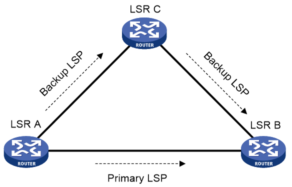
On a network where primary and backup LDP LSPs are established based on static routes, LDP-static route synchronization helps minimize traffic interruption during a traffic fallback:
1. When the primary LSP fails, LDP and static route synchronization places the static route of the primary LSP to Inactive state. MPLS traffic is switched to the backup LSP.
2. LDP-static route synchronization keeps the Inactive route state during the recovery of the primary LSP.
3. After the primary LSP completely recovers, LDP and static route synchronization places the static route to Active state, and then MPLS traffic is switched back to the primary LSP.
LDP-static route synchronization allows the primary LSP and the static route to become available synchronously. This ensures that when MPLS traffic arrives, the LSP has been established, so as to reduce MPLS traffic loss.
LDP-IGP synchronization
LDP establishes LSPs based on the IGP optimal route. If LDP is not synchronized with IGP, MPLS traffic forwarding might be interrupted.
LDP is not synchronized with IGP when one of the following situations occurs:
· A link is up, and IGP advertises and uses this link. However, LDP LSPs on this link have not been established.
· An LDP session on a link is down, and LDP LSPs on the link have been removed. However, IGP still uses this link.
· The Ordered label distribution control mode is used. IGP used the link before the local device received the label mappings from the downstream LSR to establish LDP LSPs.
After LDP-IGP synchronization is enabled, IGP advertises the actual cost of a link only when LDP convergence on the link is completed. Before LDP convergence is completed, IGP advertises the maximum cost of the link. In this way, the link is visible on the IGP topology, but IGP does not select this link as the optimal route when other links are available. Therefore, the device can avoid discarding MPLS packets when there is not an LDP LSP established on the optimal route.
LDP convergence on a link is completed when both the following situations occur:
· The local device establishes an LDP session to a minimum of one peer, and the LDP session is already in Operational state.
· The local device has distributed the label mappings to a minimum of one peer.
Notification delay for LDP convergence completion
By default, LDP immediately sends a notification to IGP that LDP convergence has completed. However, immediate notifications might cause MPLS traffic forwarding interruptions in one of the following scenarios:
· LDP peers use the Ordered label distribution control mode. The device has not received a label mapping from downstream at the time LDP notifies IGP that LDP convergence has completed.
· A large number of label mappings are distributed from downstream. Label advertisement is not completed when LDP notifies IGP that LDP convergence has completed.
To avoid traffic forwarding interruptions in these scenarios, configure the notification delay. When LDP convergence on a link is completed, LDP waits before notifying IGP.
Notification delay for LDP restart or active/standby switchover
When an LDP restart or an active/standby switchover occurs, LDP takes time to converge, and LDP notifies IGP of the LDP-IGP synchronization status as follows:
· If a notification delay is not configured, LDP immediately notifies IGP of the current synchronization states during convergence, and then updates the states after LDP convergence. This could impact IGP processing.
· If a notification delay is configured, LDP notifies IGP of the LDP-IGP synchronization states in bulk when one of the following events occurs:
¡ LDP recovers to the state before the restart or switchover.
¡ The maximum delay timer expires.
LDP FRR
LDP LFA FRR
A link or router failure on a path can cause packet loss until LDP establishes a new LSP on the new path. LDP Loop Free Alternate (LFA) FRR enables fast rerouting to minimize the failover time. LDP LFA FRR is based on IP FRR and is enabled automatically after IP FRR is enabled.
You can use one of the following methods to enable IP FRR:
· Configure an IGP to automatically calculate a backup next hop.
· Configure an IGP to specify a backup next hop by using a routing policy.
As shown in Figure 6, configure IP FRR on LSR A. The IGP automatically calculates a backup next hop or it specifies a backup next hop through a routing policy. LDP creates a primary LSP and a backup LSP according to the primary route and the backup route calculated by IGP. When the primary LSP operates correctly, it forwards the MPLS packets. When the primary LSP fails, LDP directs packets to the backup LSP.
When packets are forwarded through the backup LSP, IGP calculates the optimal path based on the new network topology. When IGP route convergence occurs, LDP establishes a new LSP according to the optimal path. If a new LSP is not established after IGP route convergence, traffic forwarding might be interrupted. As a best practice, enable LDP-IGP synchronization to work with LDP LFA FRR to reduce traffic interruption.
Figure 6 Network diagram for LDP LFA FRR
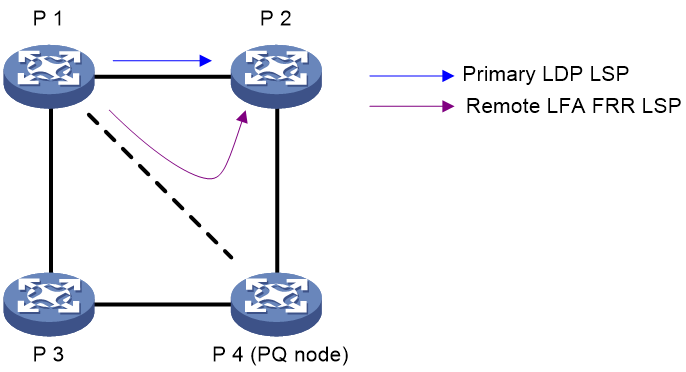
LDP remote LFA FRR
LDP LFA FRR might not be able to compute backup paths for full backup coverage on a large-scale network. To address this issue, you can deploy LDP remote LFA FRR.
As shown in Figure 7, P 1 is the source node. P 2 is the destination node. The primary LDP LSP is P 1—P 2. LDP remote LFA FRR can establish a backup LDP LSP (P 1—P 4—P 2) to protect the primary LDP LSP, as follows:
1. The IGP calculates the PQ node (P 4) using the remote LFA algorithm.
2. LDP does the following:
a. Automatically creates the remote peer according to the PQ node address.
b. Establishes the remote LDP session between the source node and the PQ node.
c. Assigns a label to the destination address on the session so as to establish the remote LFA FRR LSP (P 1—P 4—P 2).
When the primary LDP LSP fails, P 1 instantly switches traffic to the remote LFA FRR LSP to minimize traffic loss. For more information about remote LFA, see IS-IS configuration in Layer 3—IP Routing Configuration Guide.
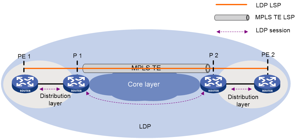
LDP over MPLS TE
As shown in Figure 8, in a layered network, MPLS TE is deployed in the core layer, and the distribution layer uses LDP as the label distribution protocol. To set up an LDP LSP across the core layer, you can establish the LDP LSP over the existing MPLS TE tunnel to simplify configuration. You only need to enable LDP on the tunnel interfaces of the ingress and egress nodes for the MPLS TE tunnel. An LDP session will be established between the tunnel ingress and egress. Label Mapping messages are advertised through the session and an LDP LSP is established. The LDP LSP is carried on the MPLS TE LSP, creating a hierarchical LSP. For more information about MPLS TE tunnels, see "Configuring MPLS TE."
Protocols
· RFC 5036, LDP Specification
· draft-ietf-mpls-ldp-ipv6-09.txt
Restrictions: Hardware compatibility with LDP
|
Hardware |
LDP compatibility |
|
MSR810, MSR810-W, MSR810-W-DB, MSR810-LM, MSR810-W-LM, MSR810-10-PoE, MSR810-LM-HK, MSR810-W-LM-HK, MSR810-LM-CNDE-SJK, MSR810-CNDE-SJK |
Yes |
|
MSR810-LMS, MSR810-LUS |
Yes |
|
MSR810-LMS-EA, MSR810-LME |
Yes |
|
MSR2600-6-X1, MSR2600-10-X1 |
Yes |
|
MSR 2630 |
No |
|
MSR3600-28, MSR3600-51 |
No |
|
MSR3600-28-SI, MSR3600-51-SI |
Yes |
|
MSR3600-28-X1, MSR3600-28-X1-DP, MSR3600-51-X1, MSR3600-51-X1-DP |
No |
|
MSR3610-I-DP, MSR3610-IE-DP, MSR3610-IE-ES, MSR3610-IE-EAD, MSR3610-I-IG, MSR3610-IE-IG |
Yes |
|
MSR3610-X1, MSR3610-X1-DP, MSR3610-X1-DC, MSR3610-X1-DP-DC |
Yes |
|
MSR 3610, MSR 3620, MSR 3620-DP, MSR 3640, MSR 3660 |
Yes |
|
MSR3610-G, MSR3620-G |
Yes |
|
Hardware |
LDP compatibility |
|
MSR810-W-WiNet, MSR810-LM-WiNet |
Yes |
|
MSR830-4LM-WiNet |
Yes |
|
MSR830-5BEI-WiNet, MSR830-6EI-WiNet, MSR830-10BEI-WiNet |
Yes |
|
MSR830-6BHI-WiNet, MSR830-10BHI-WiNet |
Yes |
|
MSR2600-6-WiNet, MSR2600-10-X1-WiNet |
Yes |
|
MSR2630-WiNet |
Yes |
|
MSR3600-28-WiNet |
No |
|
MSR3610-X1-WiNet |
Yes |
|
MSR3610-WiNet, MSR3620-10-WiNet, MSR3620-DP-WiNet, MSR3620-WiNet, MSR3660-WiNet |
Yes |
|
Hardware |
LDP compatibility |
|
MSR2630-XS |
Yes |
|
MSR3600-28-XS |
No |
|
MSR3610-XS |
Yes |
|
MSR3620-XS |
Yes |
|
MSR3610-I-XS |
Yes |
|
MSR3610-IE-XS |
Yes |
|
Hardware |
LDP compatibility |
|
MSR810-LM-GL |
Yes |
|
MSR810-W-LM-GL |
Yes |
|
MSR830-6EI-GL |
Yes |
|
MSR830-10EI-GL |
Yes |
|
MSR830-6HI-GL |
Yes |
|
MSR830-10HI-GL |
Yes |
|
MSR2600-6-X1-GL |
Yes |
|
MSR3600-28-SI-GL |
Yes |
LDP tasks at a glance
To configure LDP, perform the following tasks:
1. Enabling LDP
2. (Optional.) Tuning and optimizing LDP
¡ Configuring Hello parameters
¡ Configuring LDP session parameters
¡ Setting a DSCP value for outgoing LDP packets
3. (Optional.) Tuning and controlling LSP generation
¡ Configuring LDP to redistribute BGP unicast routes
¡ Configuring an LSP generation policy
4. (Optional.) Distributing and managing LDP labels
¡ Configuring the LDP label distribution control mode
¡ Configuring a label advertisement policy
¡ Configuring a label acceptance policy
5. (Optional.) Configuring LDP MD5 authentication
6. (Optional.) Configuring LDP loop detection
This feature is applicable to an MPLS network where most of the devices do not support the TTL mechanism, such as ATM switches.
7. (Optional.) Enhancing LDP availability
¡ Configuring LDP session protection
¡ Configuring LDP-route synchronization
8. (Optional.) Enabling SNMP notifications for LDP
Enabling LDP
Restrictions and guidelines for enabling LDP
To enable LDP, you must first enable LDP globally and then enable LDP on relevant interfaces.
Enabling LDP globally
1. Enter system view.
system-view
2. Enable LDP for the local node or for a VPN.
¡ Enable LDP for the local node and enter LDP view.
mpls ldp
¡ Execute the following commands in sequence to enable LDP for a VPN, and then enter LDP-VPN instance view:
mpls ldp
vpn-instance vpn-instance-name
By default, LDP is globally disabled.
3. Configure an LDP LSR ID.
lsr-id lsr-id
By default, the LDP LSR ID is the same as the MPLS LSR ID.
Enabling LDP on an interface
1. Enter system view.
system-view
2. Enter interface view.
interface interface-type interface-number
If the interface is bound to a VPN instance, you must enable LDP for the VPN instance by using the vpn-instance command in LDP view.
3. Enable IPv4 LDP on the interface.
mpls ldp enable
By default, IPv4 LDP is disabled on an interface.
4. Enable IPv6 LDP on the interface.
mpls ldp ipv6 enable
By default, IPv6 LDP is disabled on an interface.
Configuring Hello parameters
About hello timers
LDP has the following hello timers:
· Link Hello hold time and Link Hello interval.
If an interface is enabled with both IPv4 LDP and IPv6 LDP, the parameters configured on the interface can be used for both IPv4 and IPv6 Link Hello messages.
· Targeted Hello hold time and Targeted Hello interval for a peer.
Restrictions and guidelines for hello parameter configuration
Changes to hello parameters do not take effect on established LDP sessions. To apply the changes to existing LDP sessions on a network, you must use the reset mpls ldp command to reset all LDP sessions on that network.
Setting Link Hello timers
1. Enter system view.
system-view
2. Enter the view of the interface where you want to establish an LDP session.
interface interface-type interface-number
3. Set the Link Hello hold time.
mpls ldp timer hello-hold timeout
By default, the Link Hello hold time is 15 seconds.
4. Set the Link Hello interval.
mpls ldp timer hello-interval interval
By default, the Link Hello interval is 5 seconds.
Setting Targeted Hello timers for an LDP peer
1. Enter system view.
system-view
2. Enter LDP view.
mpls ldp
3. Specify an LDP peer and enter LDP peer view. The device will send unsolicited Targeted Hellos to the peer and can respond to the Targeted Hellos received from the peer.
targeted-peer { ipv4-address | ipv6-address }
By default, the device does not send Targeted Hellos to a peer, or respond to Targeted Hellos received from a peer.
4. Set the Targeted Hello hold time.
mpls ldp timer hello-hold timeout
By default, the Targeted Hello hold time is 45 seconds.
5. Set the Target Hello interval.
mpls ldp timer hello-interval interval
By default, the Targeted Hello interval is 15 seconds.
Configuring LDP session parameters
About LDP session parameters
An LDP session has the following parameters:
· Keepalive hold time and Keepalive interval.
· LDP transport address—IP address for establishing TCP connections.
LDP uses Basic Discovery and Extended Discovery mechanisms to discovery LDP peers and establish LDP sessions with them.
Restrictions and guidelines for configuring LDP session parameters
When you configure LDP session parameters, follow these guidelines:
· The configured LDP transport address must be the IP address of an up interface on the device. Otherwise, no LDP session can be established.
· Make sure the LDP transport addresses of the local and peer LSRs can reach each other. Otherwise, no TCP connection can be established.
· Changes to LDP session parameters do not take effect on established LDP sessions. To apply the changes to existing LDP sessions on a network, you must use the reset mpls ldp command to reset all LDP sessions on that network.
Configuring LDP sessions parameters for Basic Discovery mechanism
1. Enter system view.
system-view
2. Enter the view of the LDP session interface (the interface where you want to establish an LDP session).
interface interface-type interface-number
3. Set the Keepalive hold time.
mpls ldp timer keepalive-hold timeout
By default, the Keepalive hold time is 45 seconds.
4. Set the Keepalive interval.
mpls ldp timer keepalive-interval interval
By default, the Keepalive interval is 15 seconds.
5. Configure the IPv4 LDP transport address.
mpls ldp transport-address { ipv4-address | interface }
The default LDP IPv4 transport address is the local LSR ID if the interface where you want to establish an LDP session belongs to the public network. If the interface belongs to a VPN, the default LDP IPv4 transport address is the primary IP address of the interface.
If the LDP session interface belongs to a VPN instance, the interface with the IP address specified by this command must belong to the same VPN instance.
6. Configure the IPv6 LDP transport address.
mpls ldp transport-address ipv6-address
By default, no IPv6 LDP transport address is specified.
Configuring LDP IPv4 sessions parameters for Extended Discovery mechanism
1. Enter system view.
system-view
2. Enter LDP view.
mpls ldp
3. Specify an IPv4 LDP peer and enter LDP peer view. The device will send unsolicited IPv4 Targeted Hellos to the peer and can respond to IPv4 Targeted Hellos received from the targeted peer.
targeted-peer ipv4-address
By default, the device does not send IPv4 Targeted Hellos to a peer, or respond to IPv4 Targeted Hellos received from a peer.
4. Set the Keepalive hold time.
mpls ldp timer keepalive-hold timeout
By default, the Keepalive hold time is 45 seconds.
5. Set the Keepalive interval.
mpls ldp timer keepalive-interval interval
By default, the Keepalive interval is 15 seconds.
6. Configure the LDP transport address.
mpls ldp transport-address ipv4-address
By default, the LDP transport address is the LSR ID of the local device.
Configuring LDP IPv6 sessions parameters for Extended Discovery mechanism
1. Enter system view.
system-view
2. Enter LDP view.
mpls ldp
3. Specify an IPv6 LDP peer and enter LDP peer view. The device will send unsolicited IPv6 Targeted Hellos to the peer and can respond to IPv6 Targeted Hellos received from the targeted IPv6 peer.
targeted-peer ipv6-address
By default, the device does not send IPv6 Targeted Hellos to a peer, or respond to IPv6 Targeted Hellos received from a peer.
4. Set the Keepalive hold time.
mpls ldp timer keepalive-hold timeout
By default, the Keepalive hold time is 45 seconds.
5. Set the Keepalive interval.
mpls ldp timer keepalive-interval interval
By default, the Keepalive interval is 15 seconds.
6. Configure the LDP transport address.
mpls ldp transport-address ipv6-address
By default, the LDP IPv6 transport address is not configured.
Configuring LDP backoff
About this task
If LDP session parameters (for example, the label advertisement mode) are incompatible, two LDP peers cannot establish a session, and they will keep negotiating with each other.
The LDP backoff mechanism can mitigate this problem by using an initial delay timer and a maximum delay timer. After failing to establish a session to a peer LSR for the first time, LDP does not start an attempt until the initial delay timer expires. If the session setup fails again, LDP waits for two times the initial delay before the next attempt, and so forth until the maximum delay time is reached. After that, the maximum delay time will always take effect.
Procedure
1. Enter system view.
system-view
2. Enter LDP view or enter LDP-VPN instance view.
¡ Enter LDP view:
mpls ldp
¡ Execute the following commands in sequence to enter LDP-VPN instance view:
mpls ldp
vpn-instance vpn-instance-name
3. Set the initial delay time and maximum delay time.
backoff initial initial-time maximum maximum-time
By default, the initial delay time is 15 seconds, and the maximum delay time is 120 seconds.
Setting a DSCP value for outgoing LDP packets
About this task
To control the transmission preference of outgoing LDP packets, set a DSCP value for outgoing LDP packets.
Procedure
1. Enter system view.
system-view
2. Enter LDP view.
mpls ldp
3. Set a DSCP value for outgoing LDP packets.
dscp dscp-value
By default, the DSCP value for outgoing LDP packets is 48.
Configuring LDP to redistribute BGP unicast routes
About this task
By default, LDP automatically redistributes IGP routes, including the BGP routes that have been redistributed into IGP. Then, LDP assigns labels to the IGP routes and labeled BGP routes, if these routes are permitted by an LSP generation policy. LDP does not automatically redistribute BGP unicast routes if the routes are not redistributed into the IGP.
For example, on a carrier's carrier network where IGP is not configured between a PE of a Level 1 carrier and a CE of a Level 2 carrier, LDP cannot redistribute BGP unicast routes to assign labels to them. For this network to operate correctly, you can enable LDP to redistribute BGP unicast routes. If the routes are permitted by an LSP generation policy, LDP assigns labels to them to establish LSPs. For more information about carrier's carrier, see "Configuring MPLS L3VPN."
Procedure
1. Enter system view.
system-view
2. Enter LDP view or enter LDP-VPN instance view.
¡ Enter LDP view.
mpls ldp
¡ Execute the following commands in sequence to enter LDP-VPN instance view:
mpls ldp
vpn-instance vpn-instance-name
3. Enable LDP to redistribute BGP IPv4 unicast routes.
import bgp [ as-number ]
By default, LDP does not redistribute BGP IPv4 unicast routes.
4. Enable LDP to redistribute BGP IPv6 unicast routes.
ipv6 import bgp [ as-number ]
By default, LDP does not redistribute BGP IPv6 unicast routes.
Configuring an LSP generation policy
About this task
LDP assigns labels to the routes that have been redistributed into LDP to generate LSPs. An LSP generation policy specifies which redistributed routes can be used by LDP to generate LSPs to control the number of LSPs, as follows:
· Use all routes to establish LSPs.
· Use the routes permitted by an IP prefix list to establish LSPs. For information about IP prefix list configuration, see Layer 3—IP Routing Configuration Guide.
· Use only IPv4 host routes with a 32-bit mask or IPv6 host routes with a 128-bit prefix to establish LSPs.
Restrictions and guidelines
By default, LDP uses only IPv4 host routes with a 32-bit mask or IPv6 host routes with a 128-bit prefix to establish LSPs. The other two methods can result in more LSPs than the default policy. To change the policy, make sure the system resources and bandwidth resources are sufficient.
Procedure
1. Enter system view.
system-view
2. Enter LDP view or enter LDP-VPN instance view.
¡ Enter LDP view.
mpls ldp
¡ Execute the following commands in sequence to enter LDP-VPN instance view:
mpls ldp
vpn-instance vpn-instance-name
3. Configure an IPv4 LSP generation policy.
lsp-trigger { all | prefix-list prefix-list-name }
By default, LDP uses only the redistributed IPv4 routes with a 32-bit mask to establish LSPs.
4. Configure an IPv6 LSP generation policy.
ipv6 lsp-trigger { all | prefix-list prefix-list-name }
By default, LDP uses only the redistributed IPv6 routes with a 128-bit prefix to establish LSPs.
Configuring the LDP label distribution control mode
1. Enter system view.
system-view
2. Enter LDP view or enter LDP-VPN instance view.
¡ Enter LDP view.
mpls ldp
¡ Execute the following commands in sequence to enter LDP-VPN instance view:
mpls ldp
vpn-instance vpn-instance-name
3. Configure the label distribution control mode.
label-distribution { independent | ordered }
By default, the Ordered label distribution mode is used.
Configuring a label advertisement policy
About this task
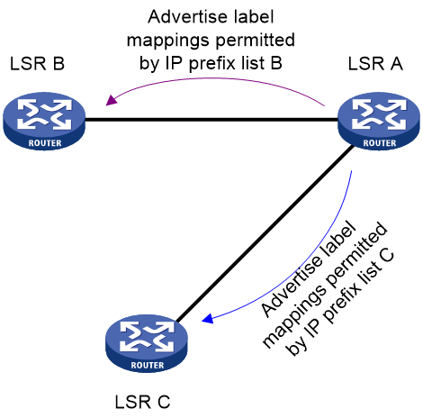
A label advertisement policy uses IP prefix lists to control the FEC-label mappings advertised to peers.
As shown in Figure 9, LSR A advertises label mappings for FECs permitted by IP prefix list B to LSR B. It advertises label mappings for FECs permitted by IP prefix list C to LSR C.
Figure 9 Label advertisement control diagram
Restrictions and guidelines
A label advertisement policy on an LSR and a label acceptance policy on its upstream LSR can achieve the same purpose. As a best practice, use label advertisement policies to reduce network load if downstream LSRs support label advertisement control.
Before you configure an LDP label advertisement policy, create an IP prefix list. For information about IP prefix list configuration, see routing policy configuration in Layer 3—IP Routing Configuration Guide.
Procedure
1. Enter system view.
system-view
2. Enter LDP view or enter LDP-VPN instance view.
¡ Enter LDP view.
mpls ldp
¡ Execute the following commands in sequence to enter LDP-VPN instance view:
mpls ldp
vpn-instance vpn-instance-name
3. Configure an IPv4 label advertisement policy.
advertise-label prefix-list prefix-list-name [ peer peer-prefix-list-name ]
By default, LDP advertises all IPv4 FEC-label mappings permitted by the LSP generation policy to all peers.
4. Configure an IPv6 label advertisement policy.
ipv6 advertise-label prefix-list prefix-list-name [ peer peer-prefix-list-name ]
By default, LDP advertises all IPv6 FEC-label mappings permitted by the LSP generation policy to all peers.
Configuring a label acceptance policy
About this task
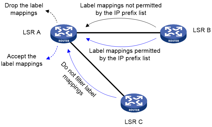
A label acceptance policy uses an IP prefix list to control the label mappings received from a peer.
As shown in Figure 10, LSR A uses an IP prefix list to filter label mappings from LSR B, and it does not filter label mappings from LSR C.
Figure 10 Label acceptance control diagram
Restrictions and guidelines
A label advertisement policy on an LSR and a label acceptance policy on its upstream LSR can achieve the same purpose. As a best practice, use the label advertisement policy to reduce network load.
You must create an IP prefix list before you configure a label acceptance policy. For information about IP prefix list configuration, see routing policy configuration in Layer 3—IP Routing Configuration Guide.
Procedure
1. Enter system view.
system-view
2. Enter LDP view or enter LDP-VPN instance view.
¡ Enter LDP view.
mpls ldp
¡ Execute the following commands in sequence to enter LDP-VPN instance view:
mpls ldp
vpn-instance vpn-instance-name
3. Configure an IPv4 label acceptance policy.
accept-label peer peer-lsr-id prefix-list prefix-list-name
By default, LDP accepts all IPv4 FEC-label mappings.
4. Configure an IPv6 label acceptance policy.
ipv6 accept-label peer peer-lsr-id prefix-list prefix-list-name
By default, LDP accepts all IPv6 FEC-label mappings.
Configuring LDP MD5 authentication
About this task
To improve security for LDP sessions, you can configure MD5 authentication for the underlying TCP connections to check the integrity of LDP messages.
Restrictions and guidelines
For two LDP peers to establish an LDP session successfully, make sure the LDP MD5 authentication configuration on the LDP peers are consistent.
Procedure
1. Enter system view.
system-view
2. Enter LDP view or enter LDP-VPN instance view.
¡ Enter LDP view.
mpls ldp
¡ Execute the following commands in sequence to enter LDP-VPN instance view:
mpls ldp
vpn-instance vpn-instance-name
3. Enable LDP MD5 authentication.
md5-authentication peer-lsr-id { cipher | plain } string
By default, LDP MD5 authentication is disabled.
Configuring LDP loop detection
About this task
The LDP loop detection feature enables LDP to detect loops during an LSP establishment. If LDP detects a loop, it terminates the LSP establishment. This feature is applicable to an MPLS network where most of the devices do not support the TTL mechanism, such as ATM switches.
LDP uses both the following methods to detect and terminate LSP loops:
· Maximum hop count loop detection—LDP adds a hop count in a label request or label mapping message. The hop count value increments by 1 on each LSR. When the maximum hop count is reached, LDP considers that a loop has occurred and terminates the LSP establishment.
The hop count is 1 for a label mapping message sent by the egress node and a label request message sent by the ingress node.
· Path vector loop detection—LDP adds LSR ID information in a label request or label mapping message. Each LSR checks whether its LSR ID is contained in the message. If it is not, the LSR adds its own LSR ID into the message. If it is, the LSR considers that a loop has occurred and terminates LSP establishment. In addition, when the number of LSR IDs in the message reaches the path vector limit, LDP also considers that a loop has occurred and terminates LSP establishment.
A label mapping message sent by the egress node does not carry the LSR ID of the egress node. A label request message sent by the ingress node does not carry the LSR ID of the ingress node.
Restrictions and guidelines
To use this feature, you must enable it on all LSRs that the LSP passes through.
To avoid extra LDP overhead, do not use this feature if most of the devices in an MPLS network support the TTL mechanism. Using the TTL mechanism can prevent endless routing loops.
Procedure
1. Enter system view.
system-view
2. Enter LDP view or enter LDP-VPN instance view.
¡ Enter LDP view.
mpls ldp
¡ Execute the following commands in sequence to enter LDP-VPN instance view:
mpls ldp
vpn-instance vpn-instance-name
3. Enable loop detection.
loop-detect
By default, loop detection is disabled.
4. (Optional.) Set the maximum hop count.
maxhops hop-number
By default, the maximum hop count is 32.
5. (Optional.) Set the path vector limit.
pv-limit pv-number
By default, the path vector limit is 32.
Configuring LDP session protection
About this task
If two LDP peers have both a direct link and an indirect link in between, you can configure this feature to protect their LDP session when the direct link fails.
LDP establishes both a Link Hello adjacency over the direct link and a Targeted Hello adjacency over the indirect link with the peer. When the direct link fails, LDP deletes the Link Hello adjacency but still maintains the Targeted Hello adjacency. In this way, the LDP session between the two peers is kept available, and the FEC-label mappings based on this session are not deleted. When the direct link recovers, the LDP peers do not need to re-establish the LDP session or re-learn the FEC-label mappings.
When you enable the session protection feature, you can also specify the session protection duration. If the Link Hello adjacency does not recover within the duration, LDP deletes the Targeted Hello adjacency and the LDP session. If you do not specify the session protection duration, the two peers will always maintain the LDP session over the Targeted Hello adjacency.
Restrictions and guidelines
LDP session protection is applicable only to IPv4 networks.
Procedure
1. Enter system view.
system-view
2. Enter LDP view.
mpls ldp
3. Enable the session protection feature.
session protection [ duration time ] [ peer peer-prefix-list-name ]
By default, session protection is disabled.
Configuring LDP GR
Prerequisites
Before you configure LDP GR, enable LDP on the GR restarter and GR helpers.
Restrictions and guidelines
The LDP GR configuration is required only on a GR restarter. Because the role (GR restarter or helper) of a device in a GR process is unpredictable, configure LDP GR on all involved devices as a best practice.
Procedure
1. Enter system view.
system-view
2. Enter LDP view.
mpls ldp
3. Enable LDP GR.
graceful-restart
By default, LDP GR is disabled.
4. (Optional.) Set the Reconnect timer for LDP GR.
graceful-restart timer reconnect reconnect-time
By default, the Reconnect time is 120 seconds.
5. (Optional.) Set the MPLS Forwarding State Holding timer for LDP GR.
graceful-restart timer forwarding-hold hold-time
By default, the MPLS Forwarding State Holding time is 180 seconds.
Configuring LDP NSR
1. Enter system view.
system-view
2. Enter LDP view.
mpls ldp
3. Enable LDP NSR.
non-stop-routing
By default, LDP NSR is disabled.
Configuring LDP-route synchronization
Restrictions and guidelines for LDP-route synchronization
After you enable LDP-IGP synchronization for an OSPF process, OSPF area, or an IS-IS process, LDP-IGP synchronization is enabled on the OSPF process interfaces or the IS-IS process interfaces.
You can execute the mpls ldp igp sync disable command to disable LDP-IGP synchronization on interfaces where LDP-IGP synchronization is not required.
LDP-IGP synchronization protection is only applicable to an IPv4 network.
LDP-IGP synchronization is not supported for an OSPF process and its OSPF areas if the OSPF process belongs to a VPN instance.
LDP-IGP synchronization is not supported for an IS-IS process that belongs to a VPN instance.
Configuring LDP-static route synchronization
1. Enter system view.
system-view
2. Enable LDP-static route synchronization.
Public network:
ip route-static { dest-address { mask-length | mask } | group group-name } interface-type interface-number ldp-sync
VPN:
ip route-static vpn-instance s-vpn-instance-name dest-address { mask-length | mask } interface-type interface-number ldp-sync
ip route-static vpn-instance s-vpn-instance-name group group-name interface-type interface-number ldp-sync
By default, LDP-static route synchronization is disabled.
For more information about this command, see static routing in Layer 3—IP Routing Command Reference.
Configuring LDP-OSPF synchronization
Configuring LDP-OSPF synchronization for an OSPF process
1. Enter system view.
system-view
2. Enter OSPF view.
ospf [ process-id | router-id router-id ] *
3. Enable LDP-OSPF synchronization.
mpls ldp sync
By default, LDP-OSPF synchronization is disabled.
4. (Optional.) Disable LDP-OSPF synchronization on an interface:
a. Return to system view.
quit
b. Enter interface view.
interface interface-type interface-number
c. Disable LDP-IGP synchronization on the interface.
mpls ldp igp sync disable
By default, LDP-IGP synchronization is enabled on an interface.
5. (Optional.) Configure LDP-OSPF synchronization parameters:
a. Return to system view.
quit
b. Enter LDP view.
mpls ldp
c. Set the delay for LDP to notify IGP of the LDP convergence.
igp sync delay time
By default, LDP immediately notifies IGP of the LDP convergence completion.
d. Set the maximum delay for LDP to notify IGP of the LDP-IGP synchronization status after an LDP restart or active/standby switchover.
igp sync delay on-restart time
By default, the maximum notification delay is 90 seconds.
Configuring LDP-OSPF synchronization for an OSPF area
1. Enter system view.
system-view
2. Enter OSPF view.
ospf [ process-id | router-id router-id ] *
3. Enter area view.
area area-id
4. Enable LDP-OSPF synchronization.
mpls ldp sync
By default, LDP-OSPF synchronization is disabled.
5. (Optional.) Disable LDP-OSPF synchronization on an interface:
a. Return to system view.
quit
b. Enter interface view.
interface interface-type interface-number
c. Disable LDP-IGP synchronization on the interface.
mpls ldp igp sync disable
By default, LDP-IGP synchronization is enabled on an interface.
6. (Optional.) Configure LDP-OSPF synchronization parameters:
a. Return to system view.
quit
b. Enter LDP view.
mpls ldp
c. Set the delay for LDP to notify IGP of the LDP convergence.
igp sync delay time
By default, LDP immediately notifies IGP of the LDP convergence completion.
d. Set the maximum delay for LDP to notify IGP of the LDP-IGP synchronization status after an LDP restart or active/standby switchover.
igp sync delay on-restart time
By default, the maximum notification delay is 90 seconds.
Configuring LDP IS-IS synchronization
1. Enter system view.
system-view
2. Enter IS-IS view.
isis [ process-id ]
3. Enable LDP-ISIS synchronization.
mpls ldp sync [ level-1 | level-2 ]
By default, LDP-ISIS synchronization is disabled.
4. (Optional.) Disable LDP-ISIS synchronization on an interface:
a. Return to system view.
quit
b. Enter interface view.
interface interface-type interface-number
c. Disable LDP-IGP synchronization on the interface.
mpls ldp igp sync disable
By default, LDP-IGP synchronization is enabled on an interface.
5. (Optional.) Configure LDP-IGP synchronization parameters:
a. Return to system view.
quit
b. Enter LDP view.
mpls ldp
c. Set the delay for LDP to notify IGP of the LDP convergence completion.
igp sync delay time
By default, LDP immediately notifies IGP of the LDP convergence completion.
d. Set the maximum delay for LDP to notify IGP of the LDP-IGP synchronization status after an LDP restart or an active/standby switchover occurs.
igp sync delay on-restart time
By default, the maximum notification delay is 90 seconds.
Configuring LDP FRR
Configuring LDP LFA FRR
LDP FRR is based on IP FRR, and is enabled automatically after IP FRR is enabled. For information about configuring IP FRR, see Layer 3—IP Routing Configuration Guide.
Configuring LDP remote LFA FRR
Restrictions and guidelines
In a remote LFA network, configure this feature on the PQ nodes.
Procedure
1. Enter system view.
system-view
2. Enter LDP view.
mpls ldp
3. Enable the device to automatically set up targeted LDP sessions on receiving Targeted Hellos.
accept target-hello { all | prefix-list prefix-list-name }
By default, the device does not automatically establish targeted LDP sessions when it receives Targeted Hellos.
Enabling SNMP notifications for LDP
About this task
This command enables generating SNMP notifications for LDP upon LDP session changes, as defined in RFC 3815. For LDP event notifications to be sent correctly, you must also configure SNMP on the device. For more information about SNMP configuration, see the network management and monitoring configuration guide for the device.
Procedure
1. Enter system view.
system-view
2. Enable SNMP notifications for LDP.
snmp-agent trap enable ldp
By default, SNMP notifications for LDP are enabled.
Display and maintenance commands for LDP
Execute display commands in any view and reset commands in user view.
|
Task |
Command |
|
Display LDP discovery information. |
display mpls ldp discovery [ vpn-instance vpn-instance-name ] [ [ interface interface-type interface-number | peer peer-lsr-id ] [ ipv6 ] | [ targeted-peer { ipv4-address | ipv6-address } ] ] [ verbose ] |
|
Display LDP FEC-label mapping information. |
display mpls ldp fec [ vpn-instance vpn-instance-name ] [ ipv4-address mask-length | ipv6-address prefix-length | [ ipv6 ] [ summary ] ] |
|
Display LDP-IGP synchronization information. |
display mpls ldp igp sync [ interface interface-type interface-number ] |
|
Display LDP interface information. |
display mpls ldp interface [ vpn-instance vpn-instance-name ] [ interface-type interface-number ] [ ipv6 ] |
|
Display LDP LSP information. |
display mpls ldp lsp [ vpn-instance vpn-instance-name ] [ ipv4-address mask-length | ipv6-address prefix-length | ipv6 ] |
|
Display LDP running parameters. |
display mpls ldp parameter [ vpn-instance vpn-instance-name ] |
|
Display LDP peer and session information. |
display mpls ldp peer [ vpn-instance vpn-instance-name ] [ peer-lsr-id ] [ verbose ] |
|
Display LDP summary information. |
display mpls ldp summary [ all | vpn-instance vpn-instance-name ] |
|
Reset LDP sessions. |
reset mpls ldp [ vpn-instance vpn-instance-name ] [ peer peer-id ] |
IPv4 LDP configuration examples
Example: Configuring LDP LSPs
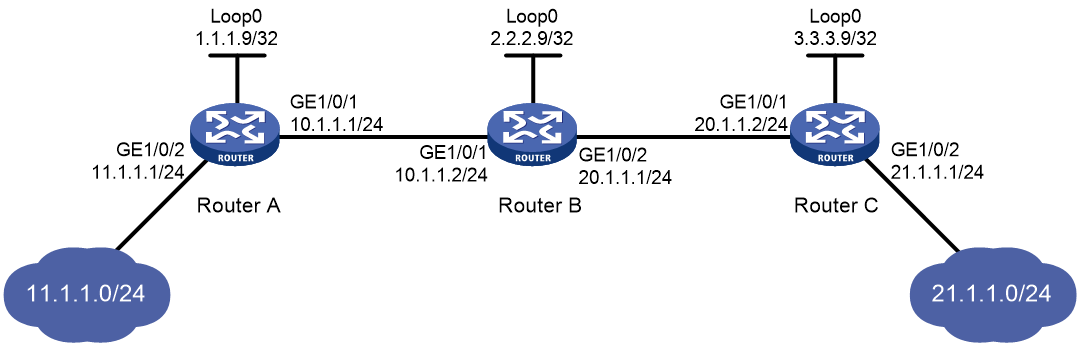
Network configuration
Router A, Router B, and Router C all support MPLS.
Configure LDP to establish LSPs between Router A and Router C, so subnets 11.1.1.0/24 and 21.1.1.0/24 can reach each other over MPLS.
Configure LDP to establish LSPs only for destinations 1.1.1.9/32, 2.2.2.9/32, 3.3.3.9/32, 11.1.1.0/24, and 21.1.1.0/24 on Router A, Router B, and Router C.
Requirements analysis
· To ensure that the LSRs establish IPv4 LSPs automatically, enable IPv4 LDP on each LSR.
· To establish IPv4 LDP LSPs, configure an IPv4 routing protocol to ensure IP connectivity between the LSRs. This example uses OSPF.
· To control the number of IPv4 LSPs, configure an IPv4 LSP generation policy on each LSR.
Procedure
1. Configure IP addresses and masks for interfaces, including the loopback interfaces, as shown in Figure 11. (Details not shown.)
2. Configure OSPF on each router to ensure IP connectivity between them:
# Configure Router A.
<RouterA> system-view
[RouterA] ospf
[RouterA-ospf-1] area 0
[RouterA-ospf-1-area-0.0.0.0] network 1.1.1.9 0.0.0.0
[RouterA-ospf-1-area-0.0.0.0] network 10.1.1.0 0.0.0.255
[RouterA-ospf-1-area-0.0.0.0] network 11.1.1.0 0.0.0.255
[RouterA-ospf-1-area-0.0.0.0] quit
[RouterA-ospf-1] quit
# Configure Router B.
<RouterB> system-view
[RouterB] ospf
[RouterB-ospf-1] area 0
[RouterB-ospf-1-area-0.0.0.0] network 2.2.2.9 0.0.0.0
[RouterB-ospf-1-area-0.0.0.0] network 10.1.1.0 0.0.0.255
[RouterB-ospf-1-area-0.0.0.0] network 20.1.1.0 0.0.0.255
[RouterB-ospf-1-area-0.0.0.0] quit
[RouterB-ospf-1] quit
# Configure Router C.
<RouterC> system-view
[RouterC] ospf
[RouterC-ospf-1] area 0
[RouterC-ospf-1-area-0.0.0.0] network 3.3.3.9 0.0.0.0
[RouterC-ospf-1-area-0.0.0.0] network 20.1.1.0 0.0.0.255
[RouterC-ospf-1-area-0.0.0.0] network 21.1.1.0 0.0.0.255
[RouterC-ospf-1-area-0.0.0.0] quit
[RouterC-ospf-1] quit
# Verify that the routers have learned the routes to each other. This example uses Router A.
[RouterA] display ip routing-table
Destinations : 21 Routes : 21
Destination/Mask Proto Pre Cost NextHop Interface
0.0.0.0/32 Direct 0 0 127.0.0.1 InLoop0
1.1.1.9/32 Direct 0 0 127.0.0.1 InLoop0
2.2.2.9/32 O_INTRA 10 1 10.1.1.2 GE1/0/1
3.3.3.9/32 O_INTRA 10 2 10.1.1.2 GE1/0/1
10.1.1.0/24 Direct 0 0 10.1.1.1 GE1/0/1
10.1.1.0/32 Direct 0 0 10.1.1.1 GE1/0/1
10.1.1.1/32 Direct 0 0 127.0.0.1 InLoop0
10.1.1.255/32 Direct 0 0 10.1.1.1 GE1/0/1
11.1.1.0/24 Direct 0 0 11.1.1.1 GE1/0/2
11.1.1.0/32 Direct 0 0 11.1.1.1 GE1/0/2
11.1.1.1/32 Direct 0 0 127.0.0.1 InLoop0
11.1.1.255/32 Direct 0 0 11.1.1.1 GE1/0/2
20.1.1.0/24 O_INTRA 10 2 10.1.1.2 GE1/0/1
21.1.1.0/24 O_INTRA 10 3 10.1.1.2 GE1/0/1
127.0.0.0/8 Direct 0 0 127.0.0.1 InLoop0
127.0.0.0/32 Direct 0 0 127.0.0.1 InLoop0
127.0.0.1/32 Direct 0 0 127.0.0.1 InLoop0
127.255.255.255/32 Direct 0 0 127.0.0.1 InLoop0
224.0.0.0/4 Direct 0 0 0.0.0.0 NULL0
224.0.0.0/24 Direct 0 0 0.0.0.0 NULL0
255.255.255.255/32 Direct 0 0 127.0.0.1 InLoop0
3. Enable MPLS and IPv4 LDP:
# Configure Router A.
[RouterA] mpls lsr-id 1.1.1.9
[RouterA] mpls ldp
[RouterA-ldp] quit
[RouterA] interface gigabitethernet 1/0/1
[RouterA-GigabitEthernet1/0/1] mpls enable
[RouterA-GigabitEthernet1/0/1] mpls ldp enable
[RouterA-GigabitEthernet1/0/1] quit
# Configure Router B.
[RouterB] mpls lsr-id 2.2.2.9
[RouterB] mpls ldp
[RouterB-ldp] quit
[RouterB] interface gigabitethernet 1/0/1
[RouterB-GigabitEthernet1/0/1] mpls enable
[RouterB-GigabitEthernet1/0/1] mpls ldp enable
[RouterB-GigabitEthernet1/0/1] quit
[RouterB] interface gigabitethernet 1/0/2
[RouterB-GigabitEthernet1/0/2] mpls enable
[RouterB-GigabitEthernet1/0/2] mpls ldp enable
[RouterB-GigabitEthernet1/0/2] quit
# Configure Router C.
[RouterC] mpls lsr-id 3.3.3.9
[RouterC] mpls ldp
[RouterC-ldp] quit
[RouterC] interface gigabitethernet 1/0/1
[RouterC-GigabitEthernet1/0/1] mpls enable
[RouterC-GigabitEthernet1/0/1] mpls ldp enable
[RouterC-GigabitEthernet1/0/1] quit
4. Configure IPv4 LSP generation policies:
# On Router A, create IP prefix list routera, and configure LDP to use only the routes permitted by the prefix list to establish LSPs.
[RouterA] ip prefix-list routera index 10 permit 1.1.1.9 32
[RouterA] ip prefix-list routera index 20 permit 2.2.2.9 32
[RouterA] ip prefix-list routera index 30 permit 3.3.3.9 32
[RouterA] ip prefix-list routera index 40 permit 11.1.1.0 24
[RouterA] ip prefix-list routera index 50 permit 21.1.1.0 24
[RouterA] mpls ldp
[RouterA-ldp] lsp-trigger prefix-list routera
[RouterA-ldp] quit
# On Router B, create IP prefix list routerb, and configure LDP to use only the routes permitted by the prefix list to establish LSPs.
[RouterB] ip prefix-list routerb index 10 permit 1.1.1.9 32
[RouterB] ip prefix-list routerb index 20 permit 2.2.2.9 32
[RouterB] ip prefix-list routerb index 30 permit 3.3.3.9 32
[RouterB] ip prefix-list routerb index 40 permit 11.1.1.0 24
[RouterB] ip prefix-list routerb index 50 permit 21.1.1.0 24
[RouterB] mpls ldp
[RouterB-ldp] lsp-trigger prefix-list routerb
[RouterB-ldp] quit
# On Router C, create IP prefix list routerc, and configure LDP to use only the routes permitted by the prefix list to establish LSPs.
[RouterC] ip prefix-list routerc index 10 permit 1.1.1.9 32
[RouterC] ip prefix-list routerc index 20 permit 2.2.2.9 32
[RouterC] ip prefix-list routerc index 30 permit 3.3.3.9 32
[RouterC] ip prefix-list routerc index 40 permit 11.1.1.0 24
[RouterC] ip prefix-list routerc index 50 permit 21.1.1.0 24
[RouterC] mpls ldp
[RouterC-ldp] lsp-trigger prefix-list routerc
[RouterC-ldp] quit
Verifying the configuration
# Display LDP LSP information on the routers, for example, on Router A.
[RouterA] display mpls ldp lsp
Status Flags: * - stale, L - liberal, B - backup, N/A - unavailable
FECs: 5 Ingress: 3 Transit: 3 Egress: 2
FEC In/Out Label Nexthop OutInterface/LSINDEX
1.1.1.9/32 3/-
-/1279(L)
2.2.2.9/32 -/3 10.1.1.2 GE1/0/1
1279/3 10.1.1.2 GE1/0/1
3.3.3.9/32 -/1278 10.1.1.2 GE1/0/1
1278/1278 10.1.1.2 GE1/0/1
11.1.1.0/24 1277/-
-/1277(L)
21.1.1.0/24 -/1276 10.1.1.2 GE1/0/1
1276/1276 10.1.1.2 GE1/0/1
# Test the connectivity of the LDP LSP from Router A to Router C.
[RouterA] ping mpls -a 11.1.1.1 ipv4 21.1.1.0 24
MPLS ping FEC 21.1.1.0/24 with 100 bytes of data:
100 bytes from 20.1.1.2: Sequence=1 time=1 ms
100 bytes from 20.1.1.2: Sequence=2 time=1 ms
100 bytes from 20.1.1.2: Sequence=3 time=8 ms
100 bytes from 20.1.1.2: Sequence=4 time=2 ms
100 bytes from 20.1.1.2: Sequence=5 time=1 ms
--- Ping statistics for FEC 21.1.1.0/24 ---
5 packets transmitted, 5 packets received, 0.0% packet loss
Round-trip min/avg/max = 1/2/8 ms
# Test the connectivity of the LDP LSP from Router C to Router A.
[RouterC] ping mpls -a 21.1.1.1 ipv4 11.1.1.0 24
MPLS ping FEC 11.1.1.0/24 with 100 bytes of data:
100 bytes from 10.1.1.1: Sequence=1 time=1 ms
100 bytes from 10.1.1.1: Sequence=2 time=1 ms
100 bytes from 10.1.1.1: Sequence=3 time=1 ms
100 bytes from 10.1.1.1: Sequence=4 time=1 ms
100 bytes from 10.1.1.1: Sequence=5 time=1 ms
--- Ping statistics for FEC 11.1.1.0/24 ---
5 packets transmitted, 5 packets received, 0.0% packet loss
Round-trip min/avg/max = 1/1/1 ms
Example: Configuring label acceptance control
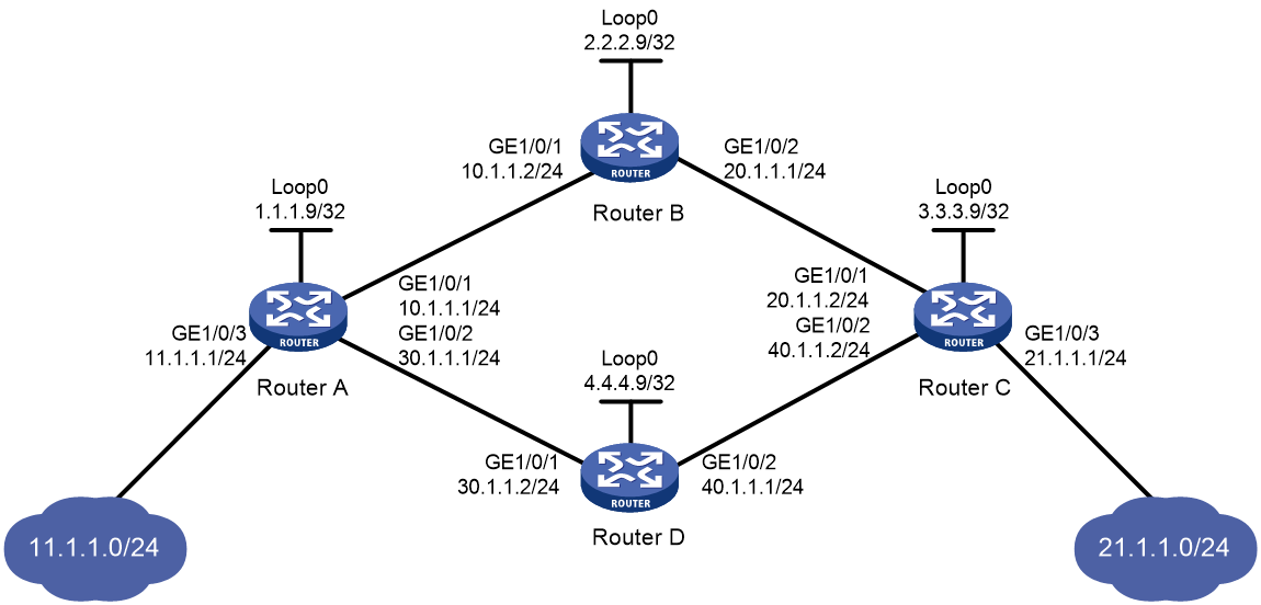
Network configuration
Two links, Router A—Router B—Router C and Router A—Router D—Router C, exist between subnets 11.1.1.0/24 and 21.1.1.0/24.
Configure LDP to establish LSPs only for routes to subnets 11.1.1.0/24 and 21.1.1.0/24.
Configure LDP to establish LSPs only on the link Router A—Router B—Router C to forward traffic between subnets 11.1.1.0/24 and 21.1.1.0/24.
Requirements analysis
· To ensure that the LSRs establish IPv4 LSPs automatically, enable IPv4 LDP on each LSR.
· To establish IPv4 LDP LSPs, configure an IPv4 routing protocol to ensure IP connectivity between the LSRs. This example uses OSPF.
· To ensure that LDP establishes IPv4 LSPs only for the routes 11.1.1.0/24 and 21.1.1.0/24, configure IPv4 LSP generation policies on each LSR.
· To ensure that LDP establishes IPv4 LSPs only over the link Router A—Router B—Router C, configure IPv4 label acceptance policies as follows:
¡ Router A accepts only the label mapping for FEC 21.1.1.0/24 received from Router B. Router A denies the label mapping for FEC 21.1.1.0/24 received from Router D.
¡ Router C accepts only the label mapping for FEC 11.1.1.0/24 received from Router B. Router C denies the label mapping for FEC 11.1.1.0/24 received from Router D.
Procedure
1. Configure IP addresses and masks for interfaces, including the loopback interfaces, as shown in Figure 12. (Details not shown.)
2. Configure OSPF on each router to ensure IP connectivity between them. (Details not shown.)
3. Enable MPLS and IPv4 LDP:
# Configure Router A.
<RouterA> system-view
[RouterA] mpls lsr-id 1.1.1.9
[RouterA] mpls ldp
[RouterA-ldp] quit
[RouterA] interface gigabitethernet 1/0/1
[RouterA-GigabitEthernet1/0/1] mpls enable
[RouterA-GigabitEthernet1/0/1] mpls ldp enable
[RouterA-GigabitEthernet1/0/1] quit
[RouterA] interface gigabitethernet 1/0/2
[RouterA-GigabitEthernet1/0/2] mpls enable
[RouterA-GigabitEthernet1/0/2] mpls ldp enable
[RouterA-GigabitEthernet1/0/2] quit
# Configure Router B.
<RouterB> system-view
[RouterB] mpls lsr-id 2.2.2.9
[RouterB] mpls ldp
[RouterB-ldp] quit
[RouterB] interface gigabitethernet 1/0/1
[RouterB-GigabitEthernet1/0/1] mpls enable
[RouterB-GigabitEthernet1/0/1] mpls ldp enable
[RouterB-GigabitEthernet1/0/1] quit
[RouterB] interface gigabitethernet 1/0/2
[RouterB-GigabitEthernet1/0/2] mpls enable
[RouterB-GigabitEthernet1/0/2] mpls ldp enable
[RouterB-GigabitEthernet1/0/2] quit
# Configure Router C.
<RouterC> system-view
[RouterC] mpls lsr-id 3.3.3.9
[RouterC] mpls ldp
[RouterC-ldp] quit
[RouterC] interface gigabitethernet 1/0/1
[RouterC-GigabitEthernet1/0/1] mpls enable
[RouterC-GigabitEthernet1/0/1] mpls ldp enable
[RouterC-GigabitEthernet1/0/1] quit
[RouterC] interface gigabitethernet 1/0/2
[RouterC-GigabitEthernet1/0/2] mpls enable
[RouterC-GigabitEthernet1/0/2] mpls ldp enable
[RouterC-GigabitEthernet1/0/2] quit
# Configure Router D.
<RouterD> system-view
[RouterD] mpls lsr-id 4.4.4.9
[RouterD] mpls ldp
[RouterD-ldp] quit
[RouterD] interface gigabitethernet 1/0/1
[RouterD-GigabitEthernet1/0/1] mpls enable
[RouterD-GigabitEthernet1/0/1] mpls ldp enable
[RouterD-GigabitEthernet1/0/1] quit
[RouterD] interface gigabitethernet 1/0/2
[RouterD-GigabitEthernet1/0/2] mpls enable
[RouterD-GigabitEthernet1/0/2] mpls ldp enable
[RouterD-GigabitEthernet1/0/2] quit
4. Configure IPv4 LSP generation policies:
# On Router A, create IP prefix list routera, and configure LDP to use only the routes permitted by the prefix list to establish LSPs.
[RouterA] ip prefix-list routera index 10 permit 11.1.1.0 24
[RouterA] ip prefix-list routera index 20 permit 21.1.1.0 24
[RouterA] mpls ldp
[RouterA-ldp] lsp-trigger prefix-list routera
[RouterA-ldp] quit
# On Router B, create IP prefix list routerb, and configure LDP to use only the routes permitted by the prefix list to establish LSPs.
[RouterB] ip prefix-list routerb index 10 permit 11.1.1.0 24
[RouterB] ip prefix-list routerb index 20 permit 21.1.1.0 24
[RouterB] mpls ldp
[RouterB-ldp] lsp-trigger prefix-list routerb
[RouterB-ldp] quit
# On Router C, create IP prefix list routerc, and configure LDP to use only the routes permitted by the prefix list to establish LSPs.
[RouterC] ip prefix-list routerc index 10 permit 11.1.1.0 24
[RouterC] ip prefix-list routerc index 20 permit 21.1.1.0 24
[RouterC] mpls ldp
[RouterC-ldp] lsp-trigger prefix-list routerc
[RouterC-ldp] quit
# On Router D, create IP prefix list routerd, and configure LDP to use only the routes permitted by the prefix list to establish LSPs.
[RouterD] ip prefix-list routerd index 10 permit 11.1.1.0 24
[RouterD] ip prefix-list routerd index 20 permit 21.1.1.0 24
[RouterD] mpls ldp
[RouterD-ldp] lsp-trigger prefix-list routerd
[RouterD-ldp] quit
5. Configure IPv4 label acceptance policies:
# On Router A, create IP prefix list prefix-from-b to permit subnet 21.1.1.0/24. Router A uses this list to filter FEC-label mappings received from Router B.
[RouterA] ip prefix-list prefix-from-b index 10 permit 21.1.1.0 24
# On Router A, create IP prefix list prefix-from-d to deny subnet 21.1.1.0/24. Router A uses this list to filter FEC-label mappings received from Router D.
[RouterA] ip prefix-list prefix-from-d index 10 deny 21.1.1.0 24
# On Router A, configure label acceptance policies to filter FEC-label mappings received from Router B and Router D.
[RouterA] mpls ldp
[RouterA-ldp] accept-label peer 2.2.2.9 prefix-list prefix-from-b
[RouterA-ldp] accept-label peer 4.4.4.9 prefix-list prefix-from-d
[RouterA-ldp] quit
# On Router C, create IP prefix list prefix-from-b to permit subnet 11.1.1.0/24. Router C uses this list to filter FEC-label mappings received from Router B.
[RouterC] ip prefix-list prefix-from-b index 10 permit 11.1.1.0 24
# On Router C, create IP prefix list prefix-from-d to deny subnet 11.1.1.0/24. Router A uses this list to filter FEC-label mappings received from Router D.
[RouterC] ip prefix-list prefix-from-d index 10 deny 11.1.1.0 24
# On Router C, configure label acceptance policies to filter FEC-label mappings received from Router B and Router D.
[RouterC] mpls ldp
[RouterC-ldp] accept-label peer 2.2.2.9 prefix-list prefix-from-b
[RouterC-ldp] accept-label peer 4.4.4.9 prefix-list prefix-from-d
[RouterC-ldp] quit
Verifying the configuration
# Display LDP LSP information on the routers, for example, on Router A.
[RouterA] display mpls ldp lsp
Status Flags: * - stale, L - liberal, B - backup, N/A - unavailable, N/A - unavailable
FECs: 2 Ingress: 1 Transit 1 Egress: 1
FEC In/Out Label Nexthop OutInterface/LSINDEX
11.1.1.0/24 1277/-
-/1148(L)
21.1.1.0/24 -/1276 10.1.1.2 GE1/0/1
1276/1276 10.1.1.2 GE1/0/1
The output shows that the next hop of the LSP for FEC 21.1.1.0/24 is Router B (10.1.1.2). The LSP has been established over the link Router A—Router B—Router C, not over the link Router A—Router D—Router C.
# Test the connectivity of the LDP LSP from Router A to Router C.
[RouterA] ping mpls -a 11.1.1.1 ipv4 21.1.1.0 24
MPLS ping FEC 21.1.1.0/24 with 100 bytes of data:
100 bytes from 20.1.1.2: Sequence=1 time=1 ms
100 bytes from 20.1.1.2: Sequence=2 time=1 ms
100 bytes from 20.1.1.2: Sequence=3 time=8 ms
100 bytes from 20.1.1.2: Sequence=4 time=2 ms
100 bytes from 20.1.1.2: Sequence=5 time=1 ms
--- Ping statistics for FEC 21.1.1.0/24 ---
5 packets transmitted, 5 packets received, 0.0% packet loss
Round-trip min/avg/max = 1/2/8 ms
# Test the connectivity of the LDP LSP from Router C to Router A.
[RouterC] ping mpls -a 21.1.1.1 ipv4 11.1.1.0 24
MPLS ping FEC 11.1.1.0/24 with 100 bytes of data:
100 bytes from 10.1.1.1: Sequence=1 time=1 ms
100 bytes from 10.1.1.1: Sequence=2 time=1 ms
100 bytes from 10.1.1.1: Sequence=3 time=1 ms
100 bytes from 10.1.1.1: Sequence=4 time=1 ms
100 bytes from 10.1.1.1: Sequence=5 time=1 ms
--- Ping statistics for FEC 11.1.1.0/24 ---
5 packets transmitted, 5 packets received, 0.0% packet loss
Round-trip min/avg/max = 1/1/1 ms
Example: Configuring label advertisement control
Network configuration
Two links, Router A—Router B—Router C and Router A—Router D—Router C, exist between subnets 11.1.1.0/24 and 21.1.1.0/24.
Configure LDP to establish LSPs only for routes to subnets 11.1.1.0/24 and 21.1.1.0/24.
Configure LDP to establish LSPs only on the link Router A—Router B—Router C to forward traffic between subnets 11.1.1.0/24 and 21.1.1.0/24.

Requirements analysis
· To ensure that the LSRs establish IPv4 LSPs automatically, enable IPv4 LDP on each LSR.
· To establish IPv4 LDP LSPs, configure an IPv4 routing protocol to ensure IP connectivity between the LSRs. This example uses OSPF.
· To ensure that LDP establishes IPv4 LSPs only for the routes 11.1.1.0/24 and 21.1.1.0/24, configure IPv4 LSP generation policies on each LSR.
· To ensure that LDP establishes IPv4 LSPs only over the link Router A—Router B—Router C, configure IPv4 label advertisement policies as follows:
¡ Router A advertises only the label mapping for FEC 11.1.1.0/24 to Router B.
¡ Router C advertises only the label mapping for FEC 21.1.1.0/24 to Router B.
¡ Router D does not advertise label mapping for FEC 21.1.1.0/24 to Router A. Router D does not advertise label mapping for FEC 11.1.1.0/24 to Router C.
Procedure
1. Configure IP addresses and masks for interfaces, including the loopback interfaces, as shown in Figure 13. (Details not shown.)
2. Configure OSPF on each router to ensure IP connectivity between them. (Details not shown.)
3. Enable MPLS and IPv4 LDP:
# Configure Router A.
<RouterA> system-view
[RouterA] mpls lsr-id 1.1.1.9
[RouterA] mpls ldp
[RouterA-ldp] quit
[RouterA] interface gigabitethernet 1/0/1
[RouterA-GigabitEthernet1/0/1] mpls enable
[RouterA-GigabitEthernet1/0/1] mpls ldp enable
[RouterA-GigabitEthernet1/0/1] quit
[RouterA] interface gigabitethernet 1/0/2
[RouterA-GigabitEthernet1/0/2] mpls enable
[RouterA-GigabitEthernet1/0/2] mpls ldp enable
[RouterA-GigabitEthernet1/0/2] quit
# Configure Router B.
<RouterB> system-view
[RouterB] mpls lsr-id 2.2.2.9
[RouterB] mpls ldp
[RouterB-ldp] quit
[RouterB] interface gigabitethernet 1/0/1
[RouterB-GigabitEthernet1/0/1] mpls enable
[RouterB-GigabitEthernet1/0/1] mpls ldp enable
[RouterB-GigabitEthernet1/0/1] quit
[RouterB] interface gigabitethernet 1/0/2
[RouterB-GigabitEthernet1/0/2] mpls enable
[RouterB-GigabitEthernet1/0/2] mpls ldp enable
[RouterB-GigabitEthernet1/0/2] quit
# Configure Router C.
<RouterC> system-view
[RouterC] mpls lsr-id 3.3.3.9
[RouterC] mpls ldp
[RouterC-ldp] quit
[RouterC] interface gigabitethernet 1/0/1
[RouterC-GigabitEthernet1/0/1] mpls enable
[RouterC-GigabitEthernet1/0/1] mpls ldp enable
[RouterC-GigabitEthernet1/0/1] quit
[RouterC] interface gigabitethernet 1/0/2
[RouterC-GigabitEthernet1/0/2] mpls enable
[RouterC-GigabitEthernet1/0/2] mpls ldp enable
[RouterC-GigabitEthernet1/0/2] quit
# Configure Router D.
<RouterD> system-view
[RouterD] mpls lsr-id 4.4.4.9
[RouterD] mpls ldp
[RouterD-ldp] quit
[RouterD] interface gigabitethernet 1/0/1
[RouterD-GigabitEthernet1/0/1] mpls enable
[RouterD-GigabitEthernet1/0/1] mpls ldp enable
[RouterD-GigabitEthernet1/0/1] quit
[RouterD] interface gigabitethernet 1/0/2
[RouterD-GigabitEthernet1/0/2] mpls enable
[RouterD-GigabitEthernet1/0/2] mpls ldp enable
[RouterD-GigabitEthernet1/0/2] quit
4. Configure IPv4 LSP generation policies:
# On Router A, create IP prefix list routera, and configure LDP to use only the routes permitted by the prefix list to establish LSPs.
[RouterA] ip prefix-list routera index 10 permit 11.1.1.0 24
[RouterA] ip prefix-list routera index 20 permit 21.1.1.0 24
[RouterA] mpls ldp
[RouterA-ldp] lsp-trigger prefix-list routera
[RouterA-ldp] quit
# On Router B, create IP prefix list routerb, and configure LDP to use only the routes permitted by the prefix list to establish LSPs.
[RouterB] ip prefix-list routerb index 10 permit 11.1.1.0 24
[RouterB] ip prefix-list routerb index 20 permit 21.1.1.0 24
[RouterB] mpls ldp
[RouterB-ldp] lsp-trigger prefix-list routerb
[RouterB-ldp] quit
# On Router C, create IP prefix list routerc, and configure LDP to use only the routes permitted by the prefix list to establish LSPs.
[RouterC] ip prefix-list routerc index 10 permit 11.1.1.0 24
[RouterC] ip prefix-list routerc index 20 permit 21.1.1.0 24
[RouterC] mpls ldp
[RouterC-ldp] lsp-trigger prefix-list routerc
[RouterC-ldp] quit
# On Router D, create IP prefix list routerd, and configure LDP to use only the routes permitted by the prefix list to establish LSPs.
[RouterD] ip prefix-list routerd index 10 permit 11.1.1.0 24
[RouterD] ip prefix-list routerd index 20 permit 21.1.1.0 24
[RouterD] mpls ldp
[RouterD-ldp] lsp-trigger prefix-list routerd
[RouterD-ldp] quit
5. Configure IPv4 label advertisement policies:
# On Router A, create IP prefix list prefix-to-b to permit subnet 11.1.1.0/24. Router A uses this list to filter FEC-label mappings advertised to Router B.
[RouterA] ip prefix-list prefix-to-b index 10 permit 11.1.1.0 24
# On Router A, create IP prefix list peer-b to permit 2.2.2.9/32. Router A uses this list to filter peers.
[RouterA] ip prefix-list peer-b index 10 permit 2.2.2.9 32
# On Router A, configure a label advertisement policy to advertise only the label mapping for FEC 11.1.1.0/24 to Router B.
[RouterA] mpls ldp
[RouterA-ldp] advertise-label prefix-list prefix-to-b peer peer-b
[RouterA-ldp] quit
# On Router C, create IP prefix list prefix-to-b to permit subnet 21.1.1.0/24. Router C uses this list to filter FEC-label mappings advertised to Router B.
[RouterC] ip prefix-list prefix-to-b index 10 permit 21.1.1.0 24
# On Router C, create IP prefix list peer-b to permit 2.2.2.9/32. Router C uses this list to filter peers.
[RouterC] ip prefix-list peer-b index 10 permit 2.2.2.9 32
# On Router C, configure a label advertisement policy to advertise only the label mapping for FEC 21.1.1.0/24 to Router B.
[RouterC] mpls ldp
[RouterC-ldp] advertise-label prefix-list prefix-to-b peer peer-b
[RouterC-ldp] quit
# On Router D, create IP prefix list prefix-to-a to deny subnet 21.1.1.0/24. Router D uses this list to filter FEC-label mappings to be advertised to Router A.
[RouterD] ip prefix-list prefix-to-a index 10 deny 21.1.1.0 24
[RouterD] ip prefix-list prefix-to-a index 20 permit 0.0.0.0 0 less-equal 32
# On Router D, create IP prefix list peer-a to permit 1.1.1.9/32. Router D uses this list to filter peers.
[RouterD] ip prefix-list peer-a index 10 permit 1.1.1.9 32
# On Router D, create IP prefix list prefix-to-c to deny subnet 11.1.1.0/24. Router D uses this list to filter FEC-label mappings to be advertised to Router C.
[RouterD] ip prefix-list prefix-to-c index 10 deny 11.1.1.0 24
[RouterD] ip prefix-list prefix-to-c index 20 permit 0.0.0.0 0 less-equal 32
# On Router D, create IP prefix list peer-c to permit subnet 3.3.3.9/32. Router D uses this list to filter peers.
[RouterD] ip prefix-list peer-c index 10 permit 3.3.3.9 32
# On Router D, configure a label advertisement policy. This policy ensures that Router D does not advertise label mappings for FEC 21.1.1.0/24 to Router A, and does not advertise label mappings for FEC 11.1.1.0/24 to Router C.
[RouterD] mpls ldp
[RouterD-ldp] advertise-label prefix-list prefix-to-a peer peer-a
[RouterD-ldp] advertise-label prefix-list prefix-to-c peer peer-c
[RouterD-ldp] quit
Verifying the configuration
# Display LDP LSP information on each router.
[RouterA] display mpls ldp lsp
Status Flags: * - stale, L - liberal, B - backup, N/A - unavailable, N/A - unavailable
FECs: 2 Ingress: 1 Transit: 1 Egress: 1
FEC In/Out Label Nexthop OutInterface/LSINDEX
11.1.1.0/24 1277/-
-/1151(L)
-/1277(L)
21.1.1.0/24 -/1276 10.1.1.2 GE1/0/1
1276/1276 10.1.1.2 GE1/0/1
[RouterB] display mpls ldp lsp
Status Flags: * - stale, L - liberal, B - backup, N/A - unavailable, N/A - unavailable
FECs: 2 Ingress: 2 Transit: 2 Egress: 0
FEC In/Out Label Nexthop OutInterface/LSINDEX
11.1.1.0/24 -/1277 10.1.1.1 GE1/0/1
1277/1277 10.1.1.1 GE1/0/1
21.1.1.0/24 -/1149 20.1.1.2 GE1/0/2
1276/1149 20.1.1.2 GE1/0/2
[RouterC] display mpls ldp lsp
Status Flags: * - stale, L - liberal, B - backup, N/A - unavailable, N/A - unavailable
FECs: 2 Ingress: 1 Transit: 1 Egress: 1
FEC In/Out Label Nexthop OutInterface/LSINDEX
11.1.1.0/24 -/1277 20.1.1.1 GE1/0/1
1148/1277 20.1.1.1 GE1/0/1
21.1.1.0/24 1149/-
-/1276(L)
-/1150(L)
[RouterD] display mpls ldp lsp
Status Flags: * - stale, L - liberal, B - backup, N/A - unavailable, N/A - unavailable
FECs: 2 Ingress: 0 Transit: 0 Egress: 2
FEC In/Out Label Nexthop OutInterface/LSINDEX
11.1.1.0/24 1151/-
-/1277(L)
21.1.1.0/24 1150/-
The output shows that Router A and Router C have received FEC-label mappings only from Router B. Router B has received FEC-label mappings from both Router A and Router C. Router D does not receive FEC-label mappings from Router A or Router C. LDP has established an LSP only over the link Router A—Router B—Router C.
# Test the connectivity of the LDP LSP from Router A to Router C.
[RouterA] ping mpls -a 11.1.1.1 ipv4 21.1.1.0 24
MPLS ping FEC 21.1.1.0/24 with 100 bytes of data:
100 bytes from 20.1.1.2: Sequence=1 time=1 ms
100 bytes from 20.1.1.2: Sequence=2 time=1 ms
100 bytes from 20.1.1.2: Sequence=3 time=8 ms
100 bytes from 20.1.1.2: Sequence=4 time=2 ms
100 bytes from 20.1.1.2: Sequence=5 time=1 ms
--- Ping statistics for FEC 21.1.1.0/24 ---
5 packets transmitted, 5 packets received, 0.0% packet loss
Round-trip min/avg/max = 1/2/8 ms
# Test the connectivity of the LDP LSP from Router C to Router A.
[RouterC] ping mpls -a 21.1.1.1 ipv4 11.1.1.0 24
MPLS ping FEC 11.1.1.0/24 with 100 bytes of data:
100 bytes from 10.1.1.1: Sequence=1 time=1 ms
100 bytes from 10.1.1.1: Sequence=2 time=1 ms
100 bytes from 10.1.1.1: Sequence=3 time=1 ms
100 bytes from 10.1.1.1: Sequence=4 time=1 ms
100 bytes from 10.1.1.1: Sequence=5 time=1 ms
--- Ping statistics for FEC 11.1.1.0/24 ---
5 packets transmitted, 5 packets received, 0.0% packet loss
Round-trip min/avg/max = 1/1/1 ms
Example: Configuring LDP FRR
Network configuration
Router S, Router A, and Router D reside in the same OSPF domain. Configure OSPF FRR so LDP can establish a primary LSP and a backup LSP on the Router S—Router D and the Router S—Router A—Router D links, respectively.
When the primary LSP operates correctly, traffic between subnets 11.1.1.0/24 and 21.1.1.0/24 is forwarded through the LSP.
When the primary LSP fails, traffic between the two subnets can be immediately switched to the backup LSP.
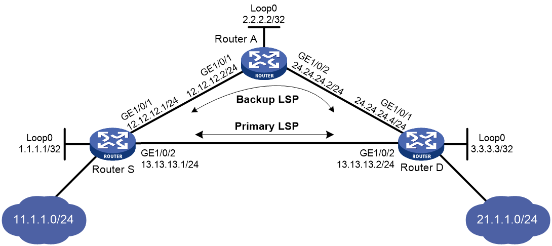
Requirements analysis
· To ensure that the LSRs establish IPv4 LSPs automatically, enable IPv4 LDP on each LSR.
· To establish IPv4 LDP LSPs, configure an IPv4 routing protocol to ensure IP connectivity between the LSRs. This example uses OSPF.
· To ensure that LDP establishes IPv4 LSPs only for the routes 11.1.1.0/24 and 21.1.1.0/24, configure IPv4 LSP generation policies on each LSR.
· To allow LDP to establish backup LSRs, configure OSPF FRR on Router S and Router D.
Procedure
1. Configure IP addresses and masks for interfaces, including the loopback interfaces, as shown in Figure 14. (Details not shown.)
2. Configure OSPF on each router to ensure IP connectivity between them. (Details not shown.)
3. Configure OSPF FRR by using one of the following methods:
¡ (Method 1.) Enable OSPF FRR to calculate a backup next hop by using the LFA algorithm:
# Configure Router S.
<RouterS> system-view
[RouterS] bfd echo-source-ip 10.10.10.10
[RouterS] ospf 1
[RouterS-ospf-1] fast-reroute lfa
[RouterS-ospf-1] quit
# Configure Router D.
<RouterD> system-view
[RouterD] bfd echo-source-ip 11.11.11.11
[RouterD] ospf 1
[RouterD-ospf-1] fast-reroute lfa
[RouterD-ospf-1] quit
¡ (Method 2.) Enable OSPF FRR to specify a backup next hop by using a routing policy:
# Configure Router S.
<RouterS> system-view
[RouterS] bfd echo-source-ip 10.10.10.10
[RouterS] ip prefix-list abc index 10 permit 21.1.1.0 24
[RouterS] route-policy frr permit node 10
[RouterS-route-policy-frr-10] if-match ip address prefix-list abc
[RouterS-route-policy-frr-10] apply fast-reroute backup-interface gigabitethernet 1/0/1 backup-nexthop 12.12.12.2
[RouterS-route-policy-frr-10] quit
[RouterS] ospf 1
[RouterS-ospf-1] fast-reroute route-policy frr
[RouterS-ospf-1] quit
# Configure Router D.
<RouterD> system-view
[RouterD] bfd echo-source-ip 10.10.10.10
[RouterD] ip prefix-list abc index 10 permit 11.1.1.0 24
[RouterD] route-policy frr permit node 10
[RouterD-route-policy-frr-10] if-match ip address prefix-list abc
[RouterD-route-policy-frr-10] apply fast-reroute backup-interface gigabitethernet 1/0/1 backup-nexthop 24.24.24.2
[RouterD-route-policy-frr-10] quit
[RouterD] ospf 1
[RouterD-ospf-1] fast-reroute route-policy frr
[RouterD-ospf-1] quit
4. Enable MPLS and IPv4 LDP:
# Configure Router S.
[RouterS] mpls lsr-id 1.1.1.1
[RouterS] mpls ldp
[RouterS-mpls-ldp] quit
[RouterS] interface gigabitethernet 1/0/1
[RouterS-GigabitEthernet1/0/1] mpls enable
[RouterS-GigabitEthernet1/0/1] mpls ldp enable
[RouterS-GigabitEthernet1/0/1] quit
[RouterS] interface gigabitethernet 1/0/2
[RouterS-GigabitEthernet1/0/2] mpls enable
[RouterS-GigabitEthernet1/0/2] mpls ldp enable
[RouterS-GigabitEthernet1/0/2] quit
# Configure Router D.
[RouterD] mpls lsr-id 3.3.3.3
[RouterD] mpls ldp
[RouterD-mpls-ldp] quit
[RouterD] interface gigabitethernet 1/0/1
[RouterD-GigabitEthernet1/0/1] mpls enable
[RouterD-GigabitEthernet1/0/1] mpls ldp enable
[RouterD-GigabitEthernet1/0/1] quit
[RouterD] interface gigabitethernet 1/0/2
[RouterD-GigabitEthernet1/0/2] mpls enable
[RouterD-GigabitEthernet1/0/2] mpls ldp enable
[RouterD-GigabitEthernet1/0/2] quit
# Configure Router A.
[RouterA] mpls lsr-id 2.2.2.2
[RouterA] mpls ldp
[RouterA-mpls-ldp] quit
[RouterA] interface gigabitethernet 1/0/1
[RouterA-GigabitEthernet1/0/1] mpls enable
[RouterA-GigabitEthernet1/0/1] mpls ldp enable
[RouterA-GigabitEthernet1/0/1] quit
[RouterA] interface gigabitethernet 1/0/2
[RouterA-GigabitEthernet1/0/2] mpls enable
[RouterA-GigabitEthernet1/0/2] mpls ldp enable
[RouterA-GigabitEthernet1/0/2] quit
5. Configure IPv4 LSP generation policies so LDP uses all static routes and IGP routes to establish LSPs:
# Configure Router S.
[RouterS] mpls ldp
[RouterS-ldp] lsp-trigger all
[RouterS-ldp] quit
# Configure Router D.
[RouterD] mpls ldp
[RouterD-ldp] lsp-trigger all
[RouterD-ldp] quit
# Configure Router A.
[RouterA] mpls ldp
[RouterA-ldp] lsp-trigger all
[RouterA-ldp] quit
Verifying the configuration
# Verify that primary and backup LSPs have been established.
[RouterS] display mpls ldp lsp 21.1.1.0 24
Status Flags: * - stale, L - liberal, B - backup, N/A - unavailable
FECs: 1 Ingress: 2 Transit: 2 Egress: 0
FEC In/Out Label Nexthop OutInterface/LSINDEX
21.1.1.0/24 -/1276 13.13.13.2 GE1/0/2
2174/1276 13.13.13.2 GE1/0/2
-/1276(B) 12.12.12.2 GE1/0/1
2174/1276(B) 12.12.12.2 GE1/0/1
IPv6 LDP configuration examples
Example: Configuring IPv6 LDP LSP
Network configuration
Router A, Router B, and Router C all support MPLS.
Configure LDP to establish IPv6 LSPs between Router A and Router C, so subnets 11::0/64 and 21::0/64 can reach each other over MPLS.
Configure LDP to establish LSPs only for destinations 100::1/128, 100::2/128, 100::3/128, 11::0/64, and 21::0/64 on Router A, Router B, and Router C.
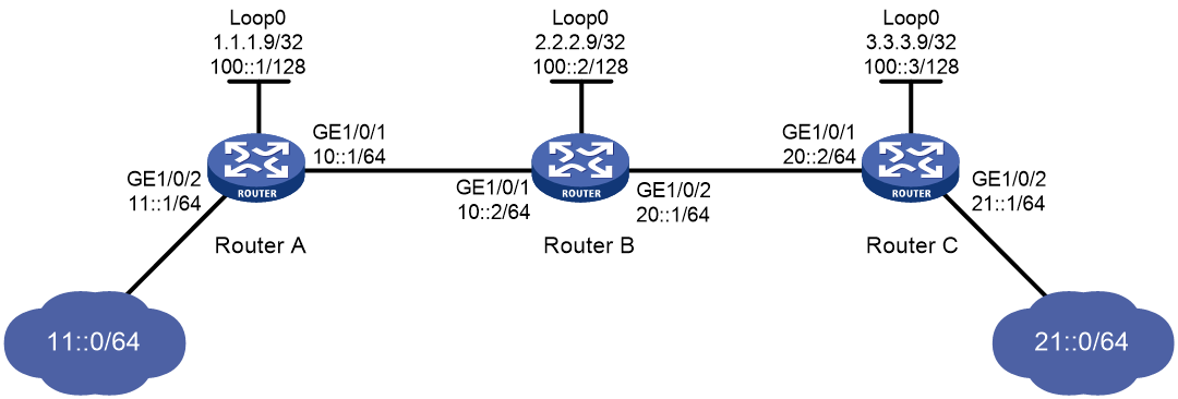
Requirements analysis
· To ensure that the LSRs establish IPv6 LSPs automatically, enable IPv6 LDP on each LSR.
· To establish IPv6 LDP LSPs, configure an IPv6 routing protocol to ensure IP connectivity between the LSRs. This example uses OSPFv3.
· To control the number of IPv6 LSPs, configure an IPv6 LSP generation policy on each LSR.
Procedure
1. Configure IPv6 addresses and prefix lengths for interfaces, including the loopback interfaces, as shown in Figure 15. (Details not shown.)
2. Configure OSPFv3 on each router to ensure IP connectivity between them:
# Configure Router A.
<RouterA> system-view
[RouterA] ospfv3
[RouterA-ospfv3-1] router-id 1.1.1.9
[RouterA-ospfv3-1] area 0
[RouterA-ospfv3-1-area-0.0.0.0] quit
[RouterA-ospfv3-1] quit
[RouterA] interface loopback 0
[RouterA-LoopBack0] ospfv3 1 area 0.0.0.0
[RouterA-LoopBack0] quit
[RouterA] interface gigabitethernet 1/0/2
[RouterA-GigabitEthernet1/0/2] ospfv3 1 area 0.0.0.0
[RouterA-GigabitEthernet1/0/2] quit
[RouterA] interface gigabitethernet 1/0/1
[RouterA-GigabitEthernet1/0/1] ospfv3 1 area 0.0.0.0
[RouterA-GigabitEthernet1/0/1] quit
# Configure Router B.
<RouterB> system-view
[RouterB] ospfv3
[RouterB-ospfv3-1] router-id 2.2.2.9
[RouterB-ospfv3-1] area 0
[RouterB-ospfv3-1-area-0.0.0.0] quit
[RouterB-ospfv3-1] quit
[RouterB] interface loopback 0
[RouterB-LoopBack0] ospfv3 1 area 0.0.0.0
[RouterB-LoopBack0] quit
[RouterB] interface gigabitethernet 1/0/1
[RouterB-GigabitEthernet1/0/1] ospfv3 1 area 0.0.0.0
[RouterB-GigabitEthernet1/0/1] quit
[RouterB] interface gigabitethernet 1/0/2
[RouterB-GigabitEthernet1/0/2] ospfv3 1 area 0.0.0.0
[RouterB-GigabitEthernet1/0/2] quit
# Configure Router C.
<RouterC> system-view
[RouterC] ospfv3
[RouterC-ospfv3-1] router-id 3.3.3.9
[RouterC-ospfv3-1] area 0
[RouterC-ospfv3-1-area-0.0.0.0] quit
[RouterC-ospfv3-1] quit
[RouterC] interface loopback 0
[RouterC-LoopBack0] ospfv3 1 area 0.0.0.0
[RouterC-LoopBack0] quit
[RouterC] interface gigabitethernet 1/0/2
[RouterC-GigabitEthernet1/0/2] ospfv3 1 area 0.0.0.0
[RouterC-GigabitEthernet1/0/2] quit
[RouterC] interface gigabitethernet 1/0/1
[RouterC-GigabitEthernet1/0/1] ospfv3 1 area 0.0.0.0
[RouterC-GigabitEthernet1/0/1] quit
# Verify that the routers have learned the routes to each other. This example uses Router A.
[RouterA] display ipv6 routing-table
Destinations : 12 Routes : 12
Destination: ::1/128 Protocol : Direct
NextHop : ::1 Preference: 0
Interface : InLoop0 Cost : 0
Destination: 10::/64 Protocol : Direct
NextHop : :: Preference: 0
Interface : GE1/0/1 Cost : 0
Destination: 10::1/128 Protocol : Direct
NextHop : ::1 Preference: 0
Interface : InLoop0 Cost : 0
Destination: 11::/64 Protocol : Direct
NextHop : :: Preference: 0
Interface : GE1/0/2 Cost : 0
Destination: 11::1/128 Protocol : Direct
NextHop : ::1 Preference: 0
Interface : InLoop0 Cost : 0
Destination: 20::/64 Protocol : O_INTRA
NextHop : FE80::20C:29FF:FE9D:EAC0 Preference: 10
Interface : GE1/0/1 Cost : 2
Destination: 21::/64 Protocol : O_INTRA
NextHop : FE80::20C:29FF:FE9D:EAC0 Preference: 10
Interface : GE1/0/1 Cost : 3
Destination: 100::1/128 Protocol : Direct
NextHop : ::1 Preference: 0
Interface : InLoop0 Cost : 0
Destination: 100::2/128 Protocol : O_INTRA
NextHop : FE80::20C:29FF:FE9D:EAC0 Preference: 10
Interface : GE1/0/1 Cost : 1
Destination: 100::3/128 Protocol : O_INTRA
NextHop : FE80::20C:29FF:FE9D:EAC0 Preference: 10
Interface : GE1/0/1 Cost : 2
Destination: FE80::/10 Protocol : Direct
NextHop : :: Preference: 0
Interface : InLoop0 Cost : 0
Destination: FF00::/8 Protocol : Direct
NextHop : :: Preference: 0
Interface : NULL0 Cost : 0
3. Enable MPLS and IPv6 LDP:
# Configure Router A.
[RouterA] mpls lsr-id 1.1.1.9
[RouterA] mpls ldp
[RouterA-ldp] quit
[RouterA] interface gigabitethernet 1/0/1
[RouterA-GigabitEthernet1/0/1] mpls enable
[RouterA-GigabitEthernet1/0/1] mpls ldp ipv6 enable
[RouterA-GigabitEthernet1/0/1] mpls ldp transport-address 10::1
[RouterA-GigabitEthernet1/0/1] quit
# Configure Router B.
[RouterB] mpls lsr-id 2.2.2.9
[RouterB] mpls ldp
[RouterB-ldp] quit
[RouterB] interface gigabitethernet 1/0/1
[RouterB-GigabitEthernet1/0/1] mpls enable
[RouterB-GigabitEthernet1/0/1] mpls ldp ipv6 enable
[RouterB-GigabitEthernet1/0/1] mpls ldp transport-address 10::2
[RouterB-GigabitEthernet1/0/1] quit
[RouterB] interface gigabitethernet 1/0/2
[RouterB-GigabitEthernet1/0/2] mpls enable
[RouterB-GigabitEthernet1/0/2] mpls ldp ipv6 enable
[RouterB-GigabitEthernet1/0/2] mpls ldp transport-address 20::1
[RouterB-GigabitEthernet1/0/2] quit
# Configure Router C.
[RouterC] mpls lsr-id 3.3.3.9
[RouterC] mpls ldp
[RouterC-ldp] quit
[RouterC] interface gigabitethernet 1/0/1
[RouterC-GigabitEthernet1/0/1] mpls enable
[RouterC-GigabitEthernet1/0/1] mpls ldp ipv6 enable
[RouterC-GigabitEthernet1/0/1] mpls ldp transport-address 20::2
[RouterC-GigabitEthernet1/0/1] quit
4. Configure IPv6 LSP generation policies:
# On Router A, create IPv6 prefix list routera, and configure LDP to use only the routes permitted by the prefix list to establish IPv6 LSPs.
[RouterA] ipv6 prefix-list routera index 10 permit 100::1 128
[RouterA] ipv6 prefix-list routera index 20 permit 100::2 128
[RouterA] ipv6 prefix-list routera index 30 permit 100::3 128
[RouterA] ipv6 prefix-list routera index 40 permit 11::0 64
[RouterA] ipv6 prefix-list routera index 50 permit 21::0 64
[RouterA] mpls ldp
[RouterA-ldp] ipv6 lsp-trigger prefix-list routera
[RouterA-ldp] quit
# On Router B, create IPv6 prefix list routerb, and configure LDP to use only the routes permitted by the prefix list to establish IPv6 LSPs.
[RouterB] ipv6 prefix-list routerb index 10 permit 100::1 128
[RouterB] ipv6 prefix-list routerb index 20 permit 100::2 128
[RouterB] ipv6 prefix-list routerb index 30 permit 100::3 128
[RouterB] ipv6 prefix-list routerb index 40 permit 11::0 64
[RouterB] ipv6 prefix-list routerb index 50 permit 21::0 64
[RouterB] mpls ldp
[RouterB-ldp] ipv6 lsp-trigger prefix-list routerb
[RouterB-ldp] quit
# On Router C, create IPv6 prefix list routerc, and configure LDP to use only the routes permitted by the prefix list to establish IPv6 LSPs.
[RouterC] ipv6 prefix-list routerc index 10 permit 100::1 128
[RouterC] ipv6 prefix-list routerc index 20 permit 100::2 128
[RouterC] ipv6 prefix-list routerc index 30 permit 100::3 128
[RouterC] ipv6 prefix-list routerc index 40 permit 11::0 64
[RouterC] ipv6 prefix-list routerc index 50 permit 21::0 64
[RouterC] mpls ldp
[RouterC-ldp] ipv6 lsp-trigger prefix-list routerc
[RouterC-ldp] quit
Verifying the configuration
# Display IPv6 LDP LSP information on the routers, for example, on Router A.
[RouterA] display mpls ldp lsp ipv6
Status Flags: * - stale, L - liberal, B - backup, N/A - unavailable
FECs: 5 Ingress: 3 Transit: 3 Egress: 2
FEC: 11::/64
In/Out Label: 2426/- OutInterface : -
Nexthop : -
In/Out Label: -/2424(L) OutInterface : -
Nexthop : -
FEC: 21::/64
In/Out Label: -/2425 OutInterface : GE1/0/1
Nexthop : FE80::20C:29FF:FE9D:EAC0
In/Out Label: 2423/2425 OutInterface : GE1/0/1
Nexthop : FE80::20C:29FF:FE9D:EAC0
FEC: 100::1/128
In/Out Label: 1040377/- OutInterface : -
Nexthop : -
In/Out Label: -/2426(L) OutInterface : -
Nexthop : -
FEC: 100::2/128
In/Out Label: -/1040379 OutInterface : GE1/0/1
Nexthop : FE80::20C:29FF:FE9D:EAC0
In/Out Label: 2425/1040379 OutInterface : GE1/0/1
Nexthop : FE80::20C:29FF:FE9D:EAC0
FEC: 100::3/128
In/Out Label: -/2427 OutInterface : GE1/0/1
Nexthop : FE80::20C:29FF:FE9D:EAC0
In/Out Label: 2424/2427 OutInterface : GE1/0/1
Nexthop : FE80::20C:29FF:FE9D:EAC0
# Test the connectivity of the IPv6 LDP LSP from Router A to Router C.
[RouterA] ping ipv6 -a 11::1 21::1
Ping6(56 data bytes) 11::1 --> 21::1, press CTRL_C to break
56 bytes from 21::1, icmp_seq=0 hlim=63 time=2.000 ms
56 bytes from 21::1, icmp_seq=1 hlim=63 time=1.000 ms
56 bytes from 21::1, icmp_seq=2 hlim=63 time=3.000 ms
56 bytes from 21::1, icmp_seq=3 hlim=63 time=3.000 ms
56 bytes from 21::1, icmp_seq=4 hlim=63 time=2.000 ms
--- Ping6 statistics for 21::1 ---
5 packets transmitted, 5 packets received, 0.0% packet loss
round-trip min/avg/max/std-dev = 1.000/2.200/3.000/0.748 ms
# Test the connectivity of the IPv6 LDP LSP from Router C to Router A.
[RouterC] ping ipv6 -a 21::1 11::1
Ping6(56 data bytes) 21::1 --> 11::1, press CTRL_C to break
56 bytes from 11::1, icmp_seq=0 hlim=63 time=2.000 ms
56 bytes from 11::1, icmp_seq=1 hlim=63 time=1.000 ms
56 bytes from 11::1, icmp_seq=2 hlim=63 time=1.000 ms
56 bytes from 11::1, icmp_seq=3 hlim=63 time=1.000 ms
56 bytes from 11::1, icmp_seq=4 hlim=63 time=1.000 ms
--- Ping6 statistics for 11::1 ---
5 packets transmitted, 5 packets received, 0.0% packet loss
round-trip min/avg/max/std-dev = 1.000/1.200/2.000/0.400 ms
Example: Configuring IPv6 label acceptance control
Network configuration
Two links, Router A—Router B—Router C and Router A—Router D—Router C, exist between subnets 11::0/64 and 21::0/64.
Configure LDP to establish LSPs only for routes to subnets 11::0/64 and 21::0/64.
Configure LDP to establish LSPs only on the link Router A—Router B—Router C to forward traffic between subnets 11::0/64 and 21::0/64.

Requirements analysis
· To ensure that the LSRs establish IPv6 LSPs automatically, enable IPv6 LDP on each LSR.
· To establish IPv6 LDP LSPs, configure an IPv6 routing protocol to ensure IP connectivity between the LSRs. This example uses OSPFv3.
· To ensure that LDP establishes IPv6 LSPs only for the routes 11::0/64 and 21::0/64, configure IPv6 LSP generation policies on each LSR.
· To ensure that LDP establishes IPv6 LSPs only over the link Router A—Router B—Router C, configure IPv6 label acceptance policies as follows:
¡ Router A accepts only the label mapping for FEC 21::0/64 received from Router B. Router A denies the label mapping for FEC 21::0/64 received from Router D.
¡ Router C accepts only the label mapping for FEC 11::0/64 received from Router B. Router C denies the label mapping for FEC 11::0/64 received from Router D.
Procedure
1. Configure IPv6 addresses and prefix lengths for interfaces, including the loopback interfaces, as shown in Figure 16. (Details not shown.)
2. Configure OSPFv3 on each router to ensure IP connectivity between them. (Details not shown.)
3. Enable MPLS and IPv6 LDP:
# Configure Router A.
<RouterA> system-view
[RouterA] mpls lsr-id 1.1.1.9
[RouterA] mpls ldp
[RouterA-ldp] quit
[RouterA] interface gigabitethernet 1/0/1
[RouterA-GigabitEthernet1/0/1] mpls enable
[RouterA-GigabitEthernet1/0/1] mpls ldp ipv6 enable
[RouterA-GigabitEthernet1/0/1] mpls ldp transport-address 10::1
[RouterA-GigabitEthernet1/0/1] quit
[RouterA] interface gigabitethernet 1/0/2
[RouterA-GigabitEthernet1/0/2] mpls enable
[RouterA-GigabitEthernet1/0/2] mpls ldp ipv6 enable
[RouterA-GigabitEthernet1/0/2] mpls ldp transport-address 30::1
[RouterA-GigabitEthernet1/0/2] quit
# Configure Router B.
<RouterB> system-view
[RouterB] mpls lsr-id 2.2.2.9
[RouterB] mpls ldp
[RouterB-ldp] quit
[RouterB] interface gigabitethernet 1/0/1
[RouterB-GigabitEthernet1/0/1] mpls enable
[RouterB-GigabitEthernet1/0/1] mpls ldp ipv6 enable
[RouterB-GigabitEthernet1/0/1] mpls ldp transport-address 10::2
[RouterB-GigabitEthernet1/0/1] quit
[RouterB] interface gigabitethernet 1/0/2
[RouterB-GigabitEthernet1/0/2] mpls enable
[RouterB-GigabitEthernet1/0/2] mpls ldp ipv6 enable
[RouterB-GigabitEthernet1/0/2] mpls ldp transport-address 20::1
[RouterB-GigabitEthernet1/0/2] quit
# Configure Router C.
<RouterC> system-view
[RouterC] mpls lsr-id 3.3.3.9
[RouterC] mpls ldp
[RouterC-ldp] quit
[RouterC] interface gigabitethernet 1/0/1
[RouterC-GigabitEthernet1/0/1] mpls enable
[RouterC-GigabitEthernet1/0/1] mpls ldp ipv6 enable
[RouterC-GigabitEthernet1/0/1] mpls ldp transport-address 20::2
[RouterC-GigabitEthernet1/0/1] quit
[RouterC] interface gigabitethernet 1/0/2
[RouterC-GigabitEthernet1/0/2] mpls enable
[RouterC-GigabitEthernet1/0/2] mpls ldp ipv6 enable
[RouterC-GigabitEthernet1/0/2] mpls ldp transport-address 40::2
[RouterC-GigabitEthernet1/0/2] quit
# Configure Router D.
<RouterD> system-view
[RouterD] mpls lsr-id 4.4.4.9
[RouterD] mpls ldp
[RouterD-ldp] quit
[RouterD] interface gigabitethernet 1/0/1
[RouterD-GigabitEthernet1/0/1] mpls enable
[RouterD-GigabitEthernet1/0/1] mpls ldp ipv6 enable
[RouterD-GigabitEthernet1/0/1] mpls ldp transport-address 30::2
[RouterD-GigabitEthernet1/0/1] quit
[RouterD] interface gigabitethernet 1/0/2
[RouterD-GigabitEthernet1/0/2] mpls enable
[RouterD-GigabitEthernet1/0/2] mpls ldp ipv6 enable
[RouterD-GigabitEthernet1/0/2] mpls ldp transport-address 40::1
[RouterD-GigabitEthernet1/0/2] quit
4. Configure IPv6 LSP generation policies:
# On Router A, create IPv6 prefix list routera, and configure LDP to use only the routes permitted by the prefix list to establish IPv6 LSPs.
[RouterA] ipv6 prefix-list routera index 10 permit 11::0 64
[RouterA] ipv6 prefix-list routera index 20 permit 21::0 64
[RouterA] mpls ldp
[RouterA-ldp] ipv6 lsp-trigger prefix-list routera
[RouterA-ldp] quit
# On Router B, create IPv6 prefix list routerb, and configure LDP to use only the routes permitted by the prefix list to establish IPv6 LSPs.
[RouterB] ipv6 prefix-list routerb index 10 permit 11::0 64
[RouterB] ipv6 prefix-list routerb index 20 permit 21::0 64
[RouterB] mpls ldp
[RouterB-ldp] ipv6 lsp-trigger prefix-list routerb
[RouterB-ldp] quit
# On Router C, create IPv6 prefix list routerc, and configure LDP to use only the routes permitted by the prefix list to establish IPv6 LSPs.
[RouterC] ipv6 prefix-list routerc index 10 permit 11::0 64
[RouterC] ipv6 prefix-list routerc index 20 permit 21::0 64
[RouterC] mpls ldp
[RouterC-ldp] ipv6 lsp-trigger prefix-list routerc
[RouterC-ldp] quit
# On Router D, create IPv6 prefix list routerd, and configure LDP to use only the routes permitted by the prefix list to establish IPv6 LSPs.
[RouterD] ipv6 prefix-list routerd index 10 permit 11::0 64
[RouterD] ipv6 prefix-list routerd index 20 permit 21::0 64
[RouterD] mpls ldp
[RouterD-ldp] ipv6 lsp-trigger prefix-list routerd
[RouterD-ldp] quit
5. Configure IPv6 label acceptance policies:
# On Router A, create IPv6 prefix list prefix-from-b to permit subnet 21::0/64. Router A uses this list to filter FEC-label mappings received from Router B.
[RouterA] ipv6 prefix-list prefix-from-b index 10 permit 21::0 64
# On Router A, create IPv6 prefix list prefix-from-d to deny subnet 21::0/64. Router A uses this list to filter FEC-label mappings received from Router D.
[RouterA] ipv6 prefix-list prefix-from-d index 10 deny 21::0 64
# On Router A, configure IPv6 label acceptance policies to filter FEC-label mappings received from Router B and Router D.
[RouterA] mpls ldp
[RouterA-ldp] ipv6 accept-label peer 2.2.2.9 prefix-list prefix-from-b
[RouterA-ldp] ipv6 accept-label peer 4.4.4.9 prefix-list prefix-from-d
[RouterA-ldp] quit
# On Router C, create IPv6 prefix list prefix-from-b to permit subnet 11::0/64. Router C uses this list to filter FEC-label mappings received from Router B.
[RouterC] ipv6 prefix-list prefix-from-b index 10 permit 11::0 64
# On Router C, create IPv6 prefix list prefix-from-d to deny subnet 11::0/64. Router A uses this list to filter FEC-label mappings received from Router D.
[RouterC] ipv6 prefix-list prefix-from-d index 10 deny 11::0 64
# On Router C, configure IPv6 label acceptance policies to filter FEC-label mappings received from Router B and Router D.
[RouterC] mpls ldp
[RouterC-ldp] ipv6 accept-label peer 2.2.2.9 prefix-list prefix-from-b
[RouterC-ldp] ipv6 accept-label peer 4.4.4.9 prefix-list prefix-from-d
[RouterC-ldp] quit
Verifying the configuration
# Display IPv6 LDP LSP information on the routers, for example, on Router A.
[RouterA] display mpls ldp lsp ipv6
Status Flags: * - stale, L - liberal, B - backup, N/A - unavailable
FECs: 2 Ingress: 1 Transit 1 Egress: 1
FEC: 11::/64
In/Out Label: 2417/- OutInterface : -
Nexthop : -
FEC: 21::/64
In/Out Label: -/2416 OutInterface : GE1/0/1
Nexthop : FE80::20C:29FF:FE9D:EAC0
In/Out Label: 2415/2416 OutInterface : GE1/0/1
Nexthop : FE80::20C:29FF:FE9D:EAC0
The output shows that the next hop of the IPv6 LSP for FEC 21::0/64 is Router B (FE80::20C:29FF:FE9D:EAC0). The IPv6 LSP has been established over the link Router A—Router B—Router C, not over the link Router A—Router D—Router C.
# Test the connectivity of the IPv6 LDP LSP from Router A to Router C.
[RouterA] ping ipv6 -a 11::1 21::1
Ping6(56 data bytes) 11::1 --> 21::1, press CTRL_C to break
56 bytes from 21::1, icmp_seq=0 hlim=63 time=4.000 ms
56 bytes from 21::1, icmp_seq=1 hlim=63 time=3.000 ms
56 bytes from 21::1, icmp_seq=2 hlim=63 time=3.000 ms
56 bytes from 21::1, icmp_seq=3 hlim=63 time=2.000 ms
56 bytes from 21::1, icmp_seq=4 hlim=63 time=1.000 ms
--- Ping6 statistics for 21::1 ---
5 packets transmitted, 5 packets received, 0.0% packet loss
round-trip min/avg/max/std-dev = 1.000/2.600/4.000/1.020 ms
# Test the connectivity of the IPv6 LDP LSP from Router C to Router A.
[RouterC] ping ipv6 -a 21::1 11::1
Ping6(56 data bytes) 21::1 --> 11::1, press CTRL_C to break
56 bytes from 11::1, icmp_seq=0 hlim=63 time=1.000 ms
56 bytes from 11::1, icmp_seq=1 hlim=63 time=2.000 ms
56 bytes from 11::1, icmp_seq=2 hlim=63 time=1.000 ms
56 bytes from 11::1, icmp_seq=3 hlim=63 time=2.000 ms
56 bytes from 11::1, icmp_seq=4 hlim=63 time=1.000 ms
--- Ping6 statistics for 11::1 ---
5 packets transmitted, 5 packets received, 0.0% packet loss
round-trip min/avg/max/std-dev = 1.000/1.400/2.000/0.490 ms
Example: Configuring IPv6 label advertisement control
Network configuration
Two links, Router A—Router B—Router C and Router A—Router D—Router C, exist between subnets 11::0/64 and 21::0/64.
Configure LDP to establish LSPs only for routes to subnets 11::0/64 and 21::0/64.
Configure LDP to establish LSPs only on the link Router A—Router B—Router C to forward traffic between subnets 11::0/64 and 21::0/64.
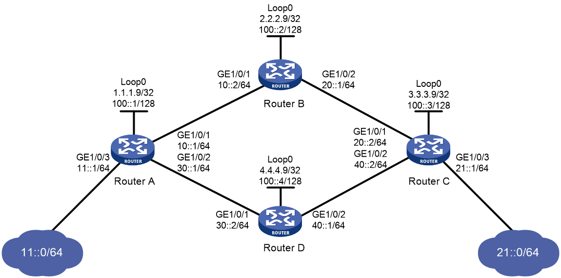
Requirements analysis
· To ensure that the LSRs establish IPv6 LSPs automatically, enable IPv6 LDP on each LSR.
· To establish IPv6 LDP LSPs, configure an IPv6 routing protocol to ensure IP connectivity between the LSRs. This example uses OSPFv3.
· To ensure that LDP establishes IPv6 LSPs only for the routes 11::0/64 and 21::0/64, configure IPv6 LSP generation policies on each LSR.
· To ensure that LDP establishes IPv6 LSPs only over the link Router A—Router B—Router C, configure IPv6 label advertisement policies as follows:
¡ Router A advertises only the label mapping for FEC 11::0/64 to Router B.
¡ Router C advertises only the label mapping for FEC 21::0/64 to Router B.
¡ Router D does not advertise label mapping for FEC 21::0/64 to Router A. Router D does not advertise label mapping for FEC 11::0/64 to Router C.
Procedure
1. Configure IPv6 addresses and prefix lengths for interfaces, including the loopback interfaces, as shown in Figure 17. (Details not shown.)
2. Configure OSPFv3 on each router to ensure IP connectivity between them. (Details not shown.)
3. Enable MPLS and IPv6 LDP:
# Configure Router A.
<RouterA> system-view
[RouterA] mpls lsr-id 1.1.1.9
[RouterA] mpls ldp
[RouterA-ldp] quit
[RouterA] interface gigabitethernet 1/0/1
[RouterA-GigabitEthernet1/0/1] mpls enable
[RouterA-GigabitEthernet1/0/1] mpls ldp ipv6 enable
[RouterA-GigabitEthernet1/0/1] mpls ldp transport-address 10::1
[RouterA-GigabitEthernet1/0/1] quit
[RouterA] interface gigabitethernet 1/0/2
[RouterA-GigabitEthernet1/0/2] mpls enable
[RouterA-GigabitEthernet1/0/2] mpls ldp ipv6 enable
[RouterA-GigabitEthernet1/0/2] mpls ldp transport-address 30::1
[RouterA-GigabitEthernet1/0/2] quit
# Configure Router B.
<RouterB> system-view
[RouterB] mpls lsr-id 2.2.2.9
[RouterB] mpls ldp
[RouterB-ldp] quit
[RouterB] interface gigabitethernet 1/0/1
[RouterB-GigabitEthernet1/0/1] mpls enable
[RouterB-GigabitEthernet1/0/1] mpls ldp ipv6 enable
[RouterB-GigabitEthernet1/0/1] mpls ldp transport-address 10::2
[RouterB-GigabitEthernet1/0/1] quit
[RouterB] interface gigabitethernet 1/0/2
[RouterB-GigabitEthernet1/0/2] mpls enable
[RouterB-GigabitEthernet1/0/2] mpls ldp ipv6 enable
[RouterB-GigabitEthernet1/0/2] mpls ldp transport-address 20::1
[RouterB-GigabitEthernet1/0/2] quit
# Configure Router C.
<RouterC> system-view
[RouterC] mpls lsr-id 3.3.3.9
[RouterC] mpls ldp
[RouterC-ldp] quit
[RouterC] interface gigabitethernet 1/0/1
[RouterC-GigabitEthernet1/0/1] mpls enable
[RouterC-GigabitEthernet1/0/1] mpls ldp ipv6 enable
[RouterC-GigabitEthernet1/0/1] mpls ldp transport-address 20::2
[RouterC-GigabitEthernet1/0/1] quit
[RouterC] interface gigabitethernet 1/0/2
[RouterC-GigabitEthernet1/0/2] mpls enable
[RouterC-GigabitEthernet1/0/2] mpls ldp ipv6 enable
[RouterC-GigabitEthernet1/0/2] mpls ldp transport-address 40::2
[RouterC-GigabitEthernet1/0/2] quit
# Configure Router D.
<RouterD> system-view
[RouterD] mpls lsr-id 4.4.4.9
[RouterD] mpls ldp
[RouterD-ldp] quit
[RouterD] interface gigabitethernet 1/0/1
[RouterD-GigabitEthernet1/0/1] mpls enable
[RouterD-GigabitEthernet1/0/1] mpls ldp ipv6 enable
[RouterD-GigabitEthernet1/0/1] mpls ldp transport-address 30::2
[RouterD-GigabitEthernet1/0/1] quit
[RouterD] interface gigabitethernet 1/0/2
[RouterD-GigabitEthernet1/0/2] mpls enable
[RouterD-GigabitEthernet1/0/2] mpls ldp ipv6 enable
[RouterD-GigabitEthernet1/0/2] mpls ldp transport-address 40::1
[RouterD-GigabitEthernet1/0/2] quit
4. Configure IPv6 LSP generation policies:
# On Router A, create IPv6 prefix list routera, and configure LDP to use only the routes permitted by the prefix list to establish IPv6 LSPs.
[RouterA] ipv6 prefix-list routera index 10 permit 11::0 64
[RouterA] ipv6 prefix-list routera index 20 permit 21::0 64
[RouterA] mpls ldp
[RouterA-ldp] ipv6 lsp-trigger prefix-list routera
[RouterA-ldp] quit
# On Router B, create IPv6 prefix list routerb, and configure LDP to use only the routes permitted by the prefix list to establish IPv6 LSPs.
[RouterB] ipv6 prefix-list routerb index 10 permit 11::0 64
[RouterB] ipv6 prefix-list routerb index 20 permit 21::0 64
[RouterB] mpls ldp
[RouterB-ldp] ipv6 lsp-trigger prefix-list routerb
[RouterB-ldp] quit
# On Router C, create IPv6 prefix list routerc, and configure LDP to use only the routes permitted by the prefix list to establish IPv6 LSPs.
[RouterC] ipv6 prefix-list routerc index 10 permit 11::0 64
[RouterC] ipv6 prefix-list routerc index 20 permit 21::0 64
[RouterC] mpls ldp
[RouterC-ldp] ipv6 lsp-trigger prefix-list routerc
[RouterC-ldp] quit
# On Router D, create IPv6 prefix list routerd, and configure LDP to use only the routes permitted by the prefix list to establish IPv6 LSPs.
[RouterD] ipv6 prefix-list routerd index 10 permit 11::0 64
[RouterD] ipv6 prefix-list routerd index 20 permit 21::0 64
[RouterD] mpls ldp
[RouterD-ldp] ipv6 lsp-trigger prefix-list routerd
[RouterD-ldp] quit
5. Configure IPv6 label advertisement policies:
# On Router A, create IPv6 prefix list prefix-to-b to permit subnet 11::0/64. Router A uses this list to filter FEC-label mappings advertised to Router B.
[RouterA] ipv6 prefix-list prefix-to-b index 10 permit 11::0 64
# On Router A, create IP prefix list peer-b to permit 2.2.2.9/32. Router A uses this list to filter peers.
[RouterA] ip prefix-list peer-b index 10 permit 2.2.2.9 32
# On Router A, configure an IPv6 label advertisement policy to advertise only the label mapping for FEC 11::0/64 to Router B.
[RouterA] mpls ldp
[RouterA-ldp] ipv6 advertise-label prefix-list prefix-to-b peer peer-b
[RouterA-ldp] quit
# On Router C, create IPv6 prefix list prefix-to-b to permit subnet 21::0/64. Router C uses this list to filter FEC-label mappings advertised to Router B.
[RouterC] ipv6 prefix-list prefix-to-b index 10 permit 21::0 64
# On Router C, create IP prefix list peer-b to permit 2.2.2.9/32. Router C uses this list to filter peers.
[RouterC] ip prefix-list peer-b index 10 permit 2.2.2.9 32
# On Router C, configure an IPv6 label advertisement policy to advertise only the label mapping for FEC 21::0/64 to Router B.
[RouterC] mpls ldp
[RouterC-ldp] ipv6 advertise-label prefix-list prefix-to-b peer peer-b
[RouterC-ldp] quit
# On Router D, create IPv6 prefix list prefix-to-a to deny subnet 21::0/64. Router D uses this list to filter FEC-label mappings to be advertised to Router A.
[RouterD] ipv6 prefix-list prefix-to-a index 10 deny 21::0 64
[RouterD] ipv6 prefix-list prefix-to-a index 20 permit 0::0 0 less-equal 128
# On Router D, create IP prefix list peer-a to permit 1.1.1.9/32. Router D uses this list to filter peers.
[RouterD] ip prefix-list peer-a index 10 permit 1.1.1.9 32
# On Router D, create IPv6 prefix list prefix-to-c to deny subnet 11::0/64. Router D uses this list to filter FEC-label mappings to be advertised to Router C.
[RouterD] ipv6 prefix-list prefix-to-c index 10 deny 11::0 64
[RouterD] ipv6 prefix-list prefix-to-c index 20 permit 0::0 0 less-equal 128
# On Router D, create IP prefix list peer-c to permit subnet 3.3.3.9/32. Router D uses this list to filter peers.
[RouterD] ip prefix-list peer-c index 10 permit 3.3.3.9 32
# On Router D, configure an IPv6 label advertisement policy. This policy ensures that Router D does not advertise label mappings for FEC 21::0/64 to Router A, and does not advertise label mappings for FEC 11::0/64 to Router C.
[RouterD] mpls ldp
[RouterD-ldp] ipv6 advertise-label prefix-list prefix-to-a peer peer-a
[RouterD-ldp] ipv6 advertise-label prefix-list prefix-to-c peer peer-c
[RouterD-ldp] quit
Verifying the configuration
# Display LDP LSP information on the routers, for example, on Router A.
[RouterA] display mpls ldp lsp ipv6
Status Flags: * - stale, L - liberal, B - backup, N/A - unavailable
FECs: 2 Ingress: 1 Transit: 1 Egress: 1
FEC: 11::/64
In/Out Label: 2417/- OutInterface : -
Nexthop : -
In/Out Label: -/1098(L) OutInterface : -
Nexthop : -
In/Out Label: -/2418(L) OutInterface : -
Nexthop : -
FEC: 21::/64
In/Out Label: -/2416 OutInterface : GE1/0/1
Nexthop : FE80::20C:29FF:FE9D:EAC0
In/Out Label: 2415/2416 OutInterface : GE1/0/1
Nexthop : FE80::20C:29FF:FE9D:EAC0
[RouterB] display mpls ldp lsp ipv6
Status Flags: * - stale, L - liberal, B - backup, N/A - unavailable
FECs: 2 Ingress: 2 Transit: 2 Egress: 0
FEC: 11::/64
In/Out Label: -/2417 OutInterface : GE1/0/1
Nexthop : FE80::20C:29FF:FE9D:EA8E
In/Out Label: 2418/2417 OutInterface : GE1/0/1
Nexthop : FE80::20C:29FF:FE9D:EA8E
FEC: 21::/64
In/Out Label: -/1099 OutInterface : GE1/0/2
Nexthop : FE80::20C:29FF:FE05:1C01
In/Out Label: 2416/1099 OutInterface : GE1/0/2
Nexthop : FE80::20C:29FF:FE05:1C01
[RouterC] display mpls ldp lsp ipv6
Status Flags: * - stale, L - liberal, B - backup, N/A - unavailable
FECs: 2 Ingress: 1 Transit: 1 Egress: 1
FEC: 11::/64
In/Out Label: -/2418 OutInterface : GE1/0/1
Nexthop : FE80::20C:29FF:FE9D:EAA2
In/Out Label: 1098/2418 OutInterface : GE1/0/1
Nexthop : FE80::20C:29FF:FE9D:EAA2
FEC: 21::/64
In/Out Label: 1099/- OutInterface : -
Nexthop : -
In/Out Label: -/2416(L) OutInterface : -
Nexthop : -
In/Out Label: -/1097(L) OutInterface : -
Nexthop : -
[RouterD] display mpls ldp lsp ipv6
Status Flags: * - stale, L - liberal, B - backup, N/A - unavailable
FECs: 2 Ingress: 0 Transit: 0 Egress: 2
FEC: 11::/64
In/Out Label: 1098/- OutInterface : -
Nexthop : -
FEC: 21::/64
In/Out Label: 1097/- OutInterface : -
Nexthop : -
The output shows that Router A and Router C have received FEC-label mappings only from Router B. Router B has received FEC-label mappings from both Router A and Router C. Router D does not receive FEC-label mappings from Router A or Router C. LDP has established an IPv6 LSP only over the link Router A—Router B—Router C.
# Test the connectivity of the IPv6 LDP LSP from Router A to Router C.
[RouterA] ping ipv6 -a 11::1 21::1
Ping6(56 data bytes) 11::1 --> 21::1, press CTRL_C to break
56 bytes from 21::1, icmp_seq=0 hlim=63 time=4.000 ms
56 bytes from 21::1, icmp_seq=1 hlim=63 time=3.000 ms
56 bytes from 21::1, icmp_seq=2 hlim=63 time=3.000 ms
56 bytes from 21::1, icmp_seq=3 hlim=63 time=2.000 ms
56 bytes from 21::1, icmp_seq=4 hlim=63 time=1.000 ms
--- Ping6 statistics for 21::1 ---
5 packets transmitted, 5 packets received, 0.0% packet loss
round-trip min/avg/max/std-dev = 1.000/2.600/4.000/1.020 ms
# Test the connectivity of the IPv6 LDP LSP from Router C to Router A.
[RouterC] ping ipv6 -a 21::1 11::1
Ping6(56 data bytes) 21::1 --> 11::1, press CTRL_C to break
56 bytes from 11::1, icmp_seq=0 hlim=63 time=1.000 ms
56 bytes from 11::1, icmp_seq=1 hlim=63 time=2.000 ms
56 bytes from 11::1, icmp_seq=2 hlim=63 time=1.000 ms
56 bytes from 11::1, icmp_seq=3 hlim=63 time=2.000 ms
56 bytes from 11::1, icmp_seq=4 hlim=63 time=1.000 ms
--- Ping6 statistics for 11::1 ---
5 packets transmitted, 5 packets received, 0.0% packet loss
round-trip min/avg/max/std-dev = 1.000/1.400/2.000/0.490 ms
Configuring mLDP
About mLDP
Multipoint extensions for LDP (mLDP) is used for multicast traffic forwarding in the IP/MPLS backbone.
mLDP P2MP
The backbone network forwards unicast packets usually through IP/MPLS because of its flexible deployment modes. To forward multicast traffic, however, the point-to-point MPLS technologies require the information source to send a separate copy of information to each receiver, wasting a lot of bandwidth.
mLDP point-to-multipoint (P2MP) is introduced to resolve this issue. mLDP P2MP entends MPLS LDP to set up P2MP paths on the IP/MPLS network to transmit multicast traffic.
mLDP P2MP nodes
As shown in Figure 18, mLDP P2MP establishes a tunnel tree (mLDP P2MP LSP) from one ingress node (PE 1) to multiple egress nodes (PE 3, PE 4, and PE 5). When needed by some receivers, the source sends only one copy of the multicast traffic to the ingress node. The traffic will be replicated on the branching node (PE 2 and P 3). In this way, no unnecessary bandwidth will be occupied.
Figure 18 mLDP P2MP network diagram
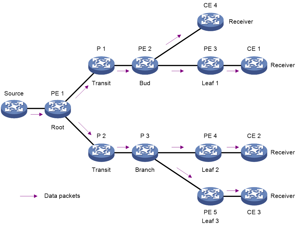
An mLDP P2MP LSP consists of the following types of nodes:
· Root—Ingress node of the mLDP P2MP LSP. The root node inserts an MPLS label to the incoming multicast packet, and propagates the multicast source and root node information to leaf nodes through BGP MVPN routes.
· Transit—Transit node, which swaps the label.
· Branch—Transit node that is connected to leaf nodes. A branch node replicates an incoming MPLS packet according to the number of leaf nodes connected, and then swaps the packets with appropriate labels.
· Leaf—A node to which a receiver is direcctly connected. A leaf node is an egress node of an mLDP P2MP LSP.
· Bud—A node that acts as both a leaf node and a branch node.
P2MP FEC Element
mLDP P2MP extends the FEC TLV for setup of an mLDP P2MP LSP. The extended FEC TLV is called the P2MP FEC Element. As show in Figure 19, the P2MP FEC Element consists of the following fields:
· Type—Type of the LSP tree established by mLDP, which is P2MP.
· Address family—Address family for the root node address. Supported address families are IPv4 and IPv6.
· Address length—Length of the root node address.
· Root node address—Address of the root node.
· Opaque length—Length of the opaque value.
· Opaque value—One or more MP opaque value elements, uniquely identifying the P2MP LSP in the context of the root node. It carries information that is meaningful to root and leaf nodes, but need not be interpreted by transit nodes.
Figure 19 P2MP FEC Element format
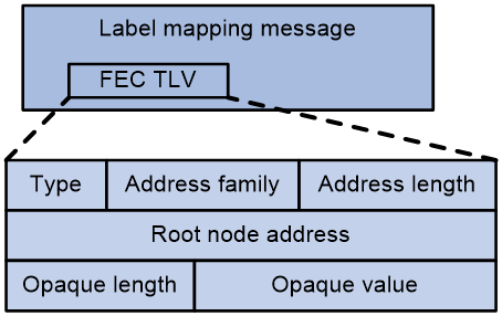
mLDP P2MP operation
Discoverying and maintaining peers
mLDP discovers and maintains peers in the same way as LDP does. For more information, see "Discovering and maintaining LDP peers."
Establishing and maintaining sessions
mLDP establishes and maintains sessions in the same way as LDP does. For more information, see "Establishing and maintaining LDP sessions."
Establising LSPs
As shown in Figure 20, an mLDP P2MP LSP is established as follows:
1. The root node delivers multicast source and root information to the leaf nodes. The leaf and transit modes select the best route to the root node and use the next hop of the best route as the upstream node.
2. Leaf nodes send label mapping messages to the upstream nodes and generates the corresponding label forwarding entries.
3. When a transit node receives a label mapping from the downstream node, it checks whether it has sent a label mapping message to the upstream node. If not, it searches the routing table to determine the upstream node, sends the label mapping message to the upstream node, and generates the corresponding label forwarding entry. If yes, the transit node does not send the label mapping message to the upstream again.
4. When the root node receives a label mapping message from the downstream, it generates the label forwarding entry accordingly.
Figure 20 mLDP P2MP LSP setup process
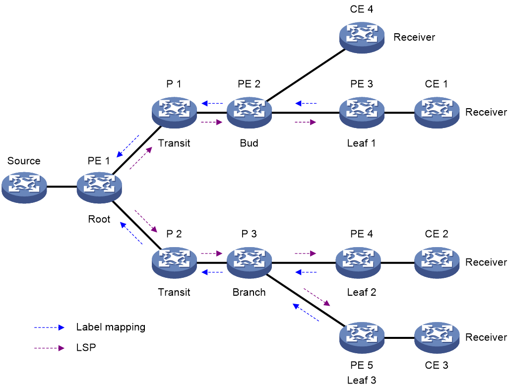
mLDP P2MP packet forwarding
As shown in Figure 21, CE 1, CE 2, and CE 3 join the same multicast group. The multicast source only needs to send one copy of information to the root node (PE 1). When the root node receives a multicast packet, it searches the multicast routing table and determines that the packet needs to be forwarded through an mLDP P2MP LSP. The root node then inserts a label to the multicast packet and forwards the packet according to the multicast label forwarding entry. The devices in the multicast group replicate the packet and label-forward the packet correctly to CE 1, and CE 2, and CE 3.
Figure 21 mLDP P2MP forwarding
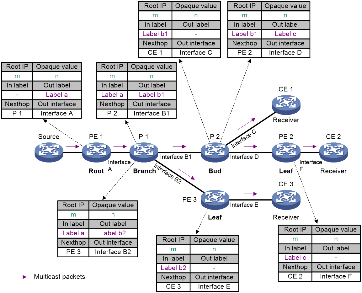
Protocols
· RFC 6388, Label Distribution Protocol Extensions for Point-to-Multipoint and Multipoint-to-Multipoint Label Switched Paths
· RFC 6512, Using Multipoint LDP When the Backbone Has No Route to the Root
· RFC 6514, BGP Encodings and Procedures for Multicast in MPLS/BGP IP VPNs
Restrictions: Hardware compatibility with mLDP
|
Hardware |
mLDP compatibility |
|
MSR810, MSR810-W, MSR810-W-DB, MSR810-LM, MSR810-W-LM, MSR810-10-PoE, MSR810-LM-HK, MSR810-W-LM-HK, MSR810-LM-CNDE-SJK, MSR810-CNDE-SJK |
No |
|
MSR810-LMS, MSR810-LUS |
No |
|
MSR810-LMS-EA, MSR810-LME |
No |
|
MSR2600-6-X1, MSR2600-10-X1 |
Yes |
|
MSR 2630 |
No |
|
MSR3600-28, MSR3600-51 |
No |
|
MSR3600-28-SI, MSR3600-51-SI |
No |
|
MSR3600-28-X1, MSR3600-28-X1-DP, MSR3600-51-X1, MSR3600-51-X1-DP |
No |
|
MSR3610-I-DP, MSR3610-IE-DP, MSR3610-IE-ES, MSR3610-IE-EAD, MSR3610-I-IG, MSR3610-IE-IG |
No |
|
MSR3610-X1, MSR3610-X1-DP, MSR3610-X1-DC, MSR3610-X1-DP-DC |
Yes |
|
MSR 3610, MSR 3620, MSR 3620-DP, MSR 3640, MSR 3660 |
Yes |
|
MSR3610-G, MSR3620-G |
No |
|
Hardware |
mLDP compatibility |
|
MSR810-W-WiNet, MSR810-LM-WiNet |
No |
|
MSR830-4LM-WiNet |
No |
|
MSR830-5BEI-WiNet, MSR830-6EI-WiNet, MSR830-10BEI-WiNet |
No |
|
MSR830-6BHI-WiNet, MSR830-10BHI-WiNet |
No |
|
MSR2600-6-WiNet, MSR2600-10-X1-WiNet |
Yes |
|
MSR2630-WiNet |
Yes |
|
MSR3600-28-WiNet |
No |
|
MSR3610-X1-WiNet |
Yes |
|
MSR3610-WiNet, MSR3620-10-WiNet, MSR3620-DP-WiNet, MSR3620-WiNet, MSR3660-WiNet |
Yes |
|
Hardware |
mLDP compatibility |
|
MSR2630-XS |
Yes |
|
MSR3600-28-XS |
No |
|
MSR3610-XS |
Yes |
|
MSR3620-XS |
Yes |
|
MSR3610-I-XS |
No |
|
MSR3610-IE-XS |
No |
|
Hardware |
mLDP compatibility |
|
MSR810-LM-GL |
No |
|
MSR810-W-LM-GL |
No |
|
MSR830-6EI-GL |
No |
|
MSR830-10EI-GL |
No |
|
MSR830-6HI-GL |
No |
|
MSR830-10HI-GL |
No |
|
MSR2600-6-X1-GL |
Yes |
|
MSR3600-28-SI-GL |
No |
mLDP P2MP tasks at a glance
To configure mLDP P2MP, perform the following tasks:
This task is required for mLDP MVPN. For more information about mLDP MVPN, see multicast VPN in IP Multicast Configuration Guide.
Enabling mLDP P2MP
Restrictions and guielines
mLDP P2MP enables mLDP for P2MP LSP setup.
Enable mLDP P2MP on all nodes in an mLDP P2MP network.
Enabling or disabling mLDP P2MP will reset all LDP sessions.
Procedure
1. Enter system view.
system-view
2. Enter LDP view.
mpls ldp
3. Enable mLDP P2MP.
mldp p2mp
By default, mLDP P2MP is disabled.
Enabling mLDP recursive
About this task
By default, the device searches only the IGP routes for the best route to the root node, and uses the next hop of the best route as its upstream node.
In an mLDP MVPN network, inter-domain (IGP area or BGP AS) LSPs need to be established for multicast traffic. As shown in Figure 22, because AS 1 and AS 2 are route-isolated from each other on the public network, PE 2 cannot get IGP routes to identify the upstream node to the root node. Therefore, CE 1's multicast traffic cannot be forwarded to CE 2.
The mLDP recursive FEC feature can resolve the previous issue. It allows the device to search both the IGP routes and the BGP MVPN routes for the best route to the root node and use the route's next hop as the new root node.
Figure 22 Inter-domain mLDP P2MP LSP diagram 1

As shown in Figure 23, after mLDP recursive FEC is enabled on ASBR-PE 2 and PE 2:
· ASBR-PE 2 searches the MVPN routes for the best route to the root node (PE 1), and uses the best route's next hop (ASBR-PE 1) as the new root node.
· PE 2 searches the MVPN routes for the best route to the root node (PE 1), and uses the best route's next hop (ASBR-PE 2) as the new root node.
In this way, mLDP P2MP LSP segments are established between PE 1 and ASBR-PE 1, ASBR-PE 1 and ASBR-PE 2, and ASBR-PE 1 and PE 2. These LSP segments form a complete mLDP P2MP LSP between PE 1 and PE 2.
Figure 23 Inter-domain mLDP P2MP LSP diagram 2
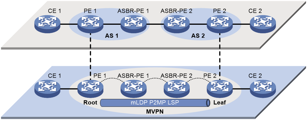
Restrictions and guielines
The mLDP recursive FEC feature enables recursive FEC for inter-domain mLDP P2MP LSP setup. You must enable this feature to establish inter-area or inter-AS LSPs for multicast traffic in an mLDP MVPN network.
Procedure
1. Enter system view.
system-view
2. Enter LDP view.
mpls ldp
3. Enable mLDP recursive FEC for inter-area or inter-AS mLDP P2MP LSP setup.
mldp recursive-fec
By default, the mLDP recursive FEC is disabled.
Display and maintenance commands for mLDP P2MP
Execute display commands in any view.
|
Task |
Command |
|
Display information about P2MP LSPs signaled by using mLDP. |
display mpls mldp lsp p2mp [ root-ip ip-address { lsp-id lsp-id | opaque-value opaque-value } ] |
