- Table of Contents
-
- 06-System
- 01-High availability group
- 02-VRRP
- 03-Track
- 04-BFD
- 05-NQA
- 06-Basic log settings
- 07-Session log settings
- 08-NAT log settings
- 09-AFT log settings
- 10-Threat log settings
- 11-Application audit log settings
- 12-URL filtering log settings
- 13-Bandwidth alarm logs
- 14-Attack defense log settings
- 15-NetShare log settings
- 16-Report settings
- 17-Session settings
- 18-Signature upgrade
- 19-Software upgrade
- 20-License management
- 21-Administrators
- 22-Date and time
- 23-Configuration management
- 24-Packet capture
- 25-Webpage Diagnosis
- 26-Packet trace
- 27-Fast Internet Access
- 28-SNMP
- 29-IRF
- 30-IRF advanced settings
- 30-IRF advanced settings(only for F50X0-D and F5000-AK5X5 firewalls)
- 31-Contexts
- 31-Contexts(only for F50X0-D and F5000-AK5X5 firewalls)
- 32-About
- 33-MAC address learning through a Layer 3 device
- 34-Bandwidth management logs
- 35-Configuration log settings
- 36-Context rate limit logging
- 37-Heartbeat log settings
- 38-Diagnostic Info
- 39-IP access logs
- 40-IP reputation log settings
- 41-IPsec diagnosis
- 42-Load balancing logging
- 43-Load balancing test
- 44-MAC authentication online users
- 45-Packet capture
- 45-Packet capture(only for F50X0-D and F5000-AK5X5 firewalls)
- 46-Ping
- 47-Reboot
- 48-Security policy log
- 49-Tracert
- 50-WAF log settings
- Related Documents
-
| Title | Size | Download |
|---|---|---|
| 30-IRF advanced settings(only for F50X0-D and F5000-AK5X5 firewalls) | 262.85 KB |
This help contains the following topics:
Introduction
Mechanisms
In this help, IRF advanced settings refer to IRF hot backup. IRF hot backup enables two IRF member devices to back up each other dynamically to ensure forwarding service continuity upon failure on one of the devices.
IRF hot backup provides the following services:
· Service backup—Backs up the data and entries of services between the two devices. This minimizes the forwarding interruption time when traffic is switched from one device to the other. IRF hot backup can perform backup for the following services:
¡ NAT444 port blocks.
¡ Sessions.
¡ DNS.
¡ HTTP.
¡ IPsec SAs.
Support for the services depends on the device model.
· Traffic migration—Switches traffic from one device to the other by using a redundancy group. A redundancy group allows traffic to enter and leave the hot backup system through the same device. The redundancy group works with Track to detect uplink and downlink failures. When detecting a failure, the redundancy group switches all its members from the failed device to the other device.
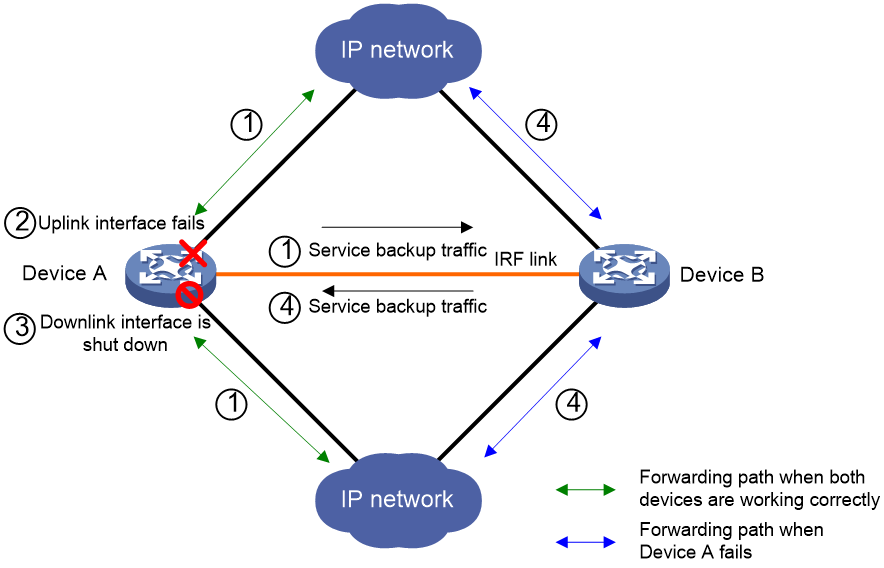
IRF hot backup works as follows, as shown in Figure 1:
1. When both devices are working correctly, Device A forwards traffic, and service data and entries are backed up from Device A to Device B.
2. Track detects that the uplink interface of Device A fails.
3. The redundancy group shuts down the downlink interface of Device A.
4. Traffic is switched to Device B for forwarding. Because Device B already has service data and entries, traffic migration almost has no impact on the services.
Figure 1 IRF hot backup workflow
Operating modes
IRF hot backup supports the following modes:
· Active/standby mode—Only one device processes services.
· Dual-active mode—Both devices process services.
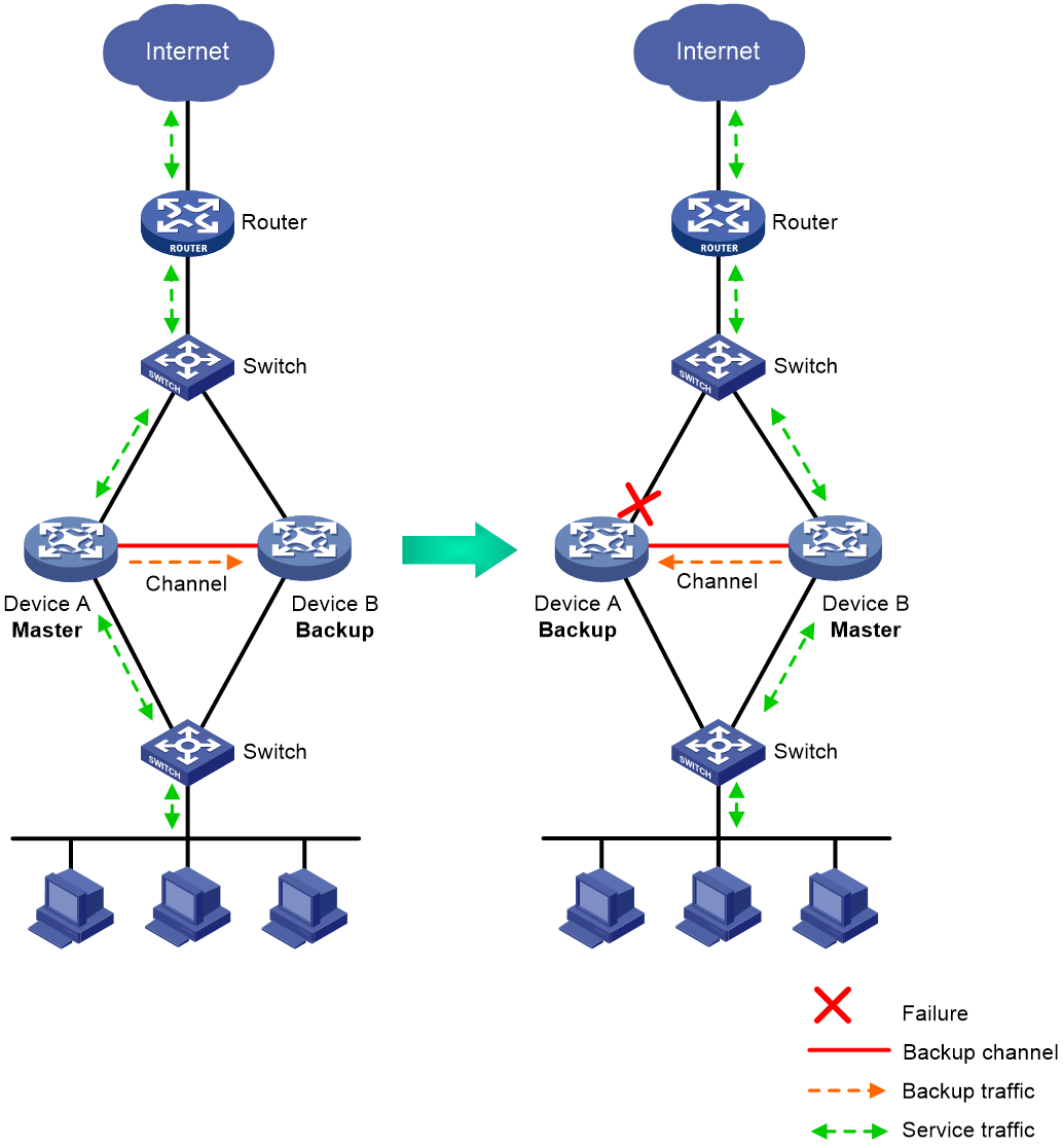
Active/standby mode
In active/standby mode, one device acts as the master to process services, and the other device acts as the backup, as shown in Figure 2. When an interface or link on the master fails or the master fails, the backup takes over the master role to process services.
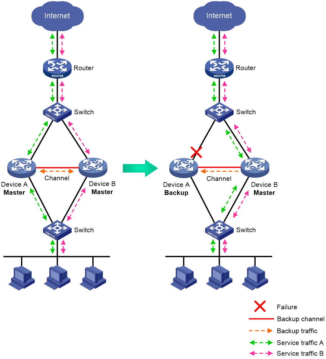
Dual-active mode
In dual-active mode, both devices process services to increase capability of the hot backup system, as shown in Figure 3. When one device fails, its traffic is switched to the other device for forwarding.
Redundancy groups
Redundancy group nodes
A redundancy group contains two nodes. A redundancy group node can act as the primary or secondary node. Only the primary node can forward traffic. When both nodes are working correctly, only interfaces and CPUs on the primary node are processing traffic (such as forwarding packets and creating session entries). The secondary node acts as a backup and does not process traffic as long as the primary node is working correctly.
Redundancy group nodes are associated with physical devices in a cluster by member IDs. The primary node can be the master device or standby device in a cluster. Typically, the primary node is the master device.
Member interfaces
You can assign physical interfaces to a redundancy group by binding them to their respective redundancy group nodes.
For symmetric traffic switchover, you must bind a minimum of one downlink interface and a minimum of one uplink interface with each node of the redundancy group.
The state of the member physical interfaces changes with the state of the redundancy group nodes. Only the member interfaces on the primary node can forward traffic.
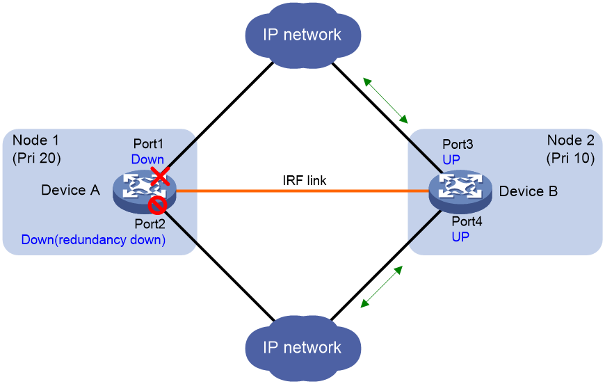
As shown in Figure 4, Port 1 and Port 2 are on Node 1, and Port 3 and Port 4 are on Node 2. When Node 1 is in primary state, Port 1 and Port 2 are up to forward traffic, while Port 3 and Port 4 are shut down by the Reth module.
When Port 1 goes down, the Reth module places Node 1 in secondary state and shuts down Port 2. Node 2 changes to the primary state, and Port 3 and Port 4 come up to forward traffic, as shown in Figure 5.
Figure 4 States of the member interfaces when both nodes are operating correctly
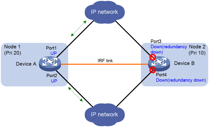
Figure 5 States of the member interfaces after a switchover
Reth interfaces
To use Reth interfaces for symmetric forwarding, you must assign two Reth interfaces to a redundancy group: one for uplink traffic and the other for downlink traffic. The Reth interfaces must meet the following requirements:
· The Reth interface for uplink traffic contains one uplink port on each redundancy group node.
· The Reth interface for downlink traffic contains one downlink port on each redundancy group node.
· The high-priority member of each Reth interface belongs to the high-priority node.
The state of each Reth interface's members depends on the state of the redundancy group nodes.
· When the high-priority node is in primary state, the high-priority member is active.
· When the low-priority node is in primary state, the low-priority member is active.
As shown in Figure 6, redundancy group 1 contains Reth 1 for uplink traffic and Reth 2 for downlink traffic. Reth 1 contains Port 1 (on Node 1) and Port 3 (on Node 2). Reth 2 contains Port 2 (on Node 1) and Port 4 (on Node 2).
When Node 1 is in primary state, Port 1 in Reth 1 and Port 2 in Reth 2 are active to forward uplink and downlink traffic, respectively.
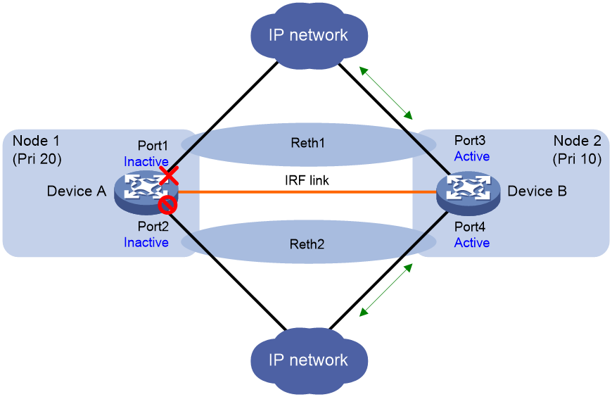
When Port 1 fails, the Reth module places Node 1 in secondary state and shuts down Port 2, as shown in Figure 7. Node 2 changes to the primary state, and Port 3 and Port 4 become active to forward uplink and downlink traffic.
Figure 6 States of each Reth interface's members when both nodes are operating correctly
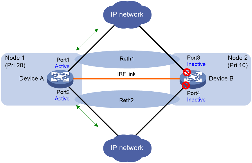
Figure 7 States of each Reth interface's members after a switchover
Failover groups
A failover group can be used by a service module (for example, NAT) to provide service backup between CPUs.
A failover group contains one primary CPU and one secondary CPU. If you are assigning a failover group to a redundancy group, configure the CPU on the high-priority redundancy node as the primary CPU in the failover group.
In a redundancy group, the states of the CPUs in a failover group change in consistency with the redundancy group nodes when both CPUs are operating correctly.
· When the high-priority node is in primary state, the primary CPU processes services and the secondary CPU backs up services.
· When the low-priority node is in primary state, the secondary CPU processes services and the primary CPU backs up services.
Failover and fallback
In a redundancy group, one node is in primary state, and the other node is in secondary state. Only the primary node forwards traffic. When the primary node fails, the redundancy group switches over to the secondary node. This mechanism ensures path symmetry for traffic.
A redundancy group performs a switchover as follows:
1. When both redundancy group nodes are operating correctly, the redundancy group forwards traffic through the primary node and backs up services and data to the secondary node.
2. When the upstream interface on the primary node fails, the redundancy group shuts down the downstream interface on the primary node and switches traffic over to the secondary node.
When the primary node recovers, the redundancy group switches traffic back to the primary node.
Redundancy group switchovers include automatic switchovers and manual switchovers.
· Automatic switchover—A redundancy group cooperates with the Track module to monitor link and interface status for automatic switchovers.
· Manual switchover—You issue a manual switchover request.
When a switchover is triggered, traffic is not migrated immediately. Whether traffic is migrated depends on the status of the primary node and the preemption delay timer.
Preemption delay timer
Configure IRF hot backup
Prerequisites
Set up an IRF fabric by using two devices before you configure IRF hot backup on them.
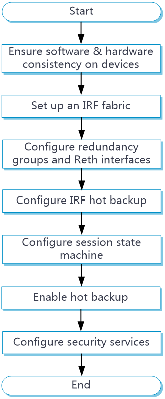
IRF hot backup configuration flow
Figure 8 IRF hot backup configuration flow chart
Configure redundancy groups and Reth interfaces
1. Click the System tab.
2. In the navigation pane, select Virtualization Advanced Settings > IRF Advanced Settings.
The IRF Advanced Settings page opens.
3. Click Redundancy groups.
4. Click Create, configure the redundancy group name, and click OK.
5. Configure the redundancy group, Reth interfaces, and failover groups. For more information about the related parameters, see Table 1 and Table 2.
Table 1 Redundancy group parameters
|
Parameter |
Description |
|
Member Devices |
Specify a maximum of two member devices for the redundancy group. One member device is the primary device, and the other is the secondary device. Typically, the primary device is the IRF master. |
|
Member ID |
Set the IRF member ID of each device. |
|
Member interfaces |
Specify the member interfaces of the redundancy group. Configure member interfaces when the upstream and downstream devices of the hot backup system run a dynamic routing protocol. In this scenario, you must configure the uplink and downlink physical Ethernet interfaces of the member devices as member interfaces of the redundancy group. |
|
Reth interfaces |
Configure Reth interfaces. Use Reth interfaces when the upstream and downstream devices of the hot backup system do not run a dynamic routing protocol, for example, when VRRP is used. For more information, see Table 3. |
|
Track |
Associate track entries with the redundancy group to trigger redundancy group member switchover. |
Table 2 Advanced settings for a redundancy group
|
Parameter |
Description |
|
Hold-down timer |
Set the hold-down timer. This timer specifies the minimum interval between two switchovers to prevent frequent switchovers. |
|
Preemption delay timer |
Set the preemption delay timer. This timer specifies the delay before a switchback. |
|
Manual switchover |
Manually perform a switchover or switchback. |
6. Click Create in the Reth interfaces area.
7. Configure the Reth interface. For more information about the related parameters, see Table 3.
Table 3 Reth interface parameters
|
Parameter |
Description |
|
Primary member interface |
Select an uplink or downlink interface on the primary member device. |
|
Secondary member interface |
Select an uplink or downlink interface on the secondary member device. |
You can configure multiple Reth interfaces in a redundancy group. Typically, you must configure at least two Reth interfaces. One Reth interface contains the uplink interfaces on the member devices, and the other contains the downlink interfaces on the member devices.
8. In the Failover groups area, click Create.
9. Configure the failover group. For more information about the related parameters, see Table 4.
Table 4 Failover group parameters
|
Parameter |
Description |
|
Primary slot number |
Specify the slot number of the primary CPU. The security module in the specified slot will process services. |
|
Primary CPU |
Specify the ID of the primary CPU. The specified CPU will process services. |
|
Secondary slot number |
Specify the slot number of the secondary CPU. The security module in the specified slot will not process services. |
|
Secondary CPU |
Specify the ID of the secondary CPU. The specified CPU will not process services. |
Configure hot backup on the IRF fabric
1. Click the System tab.
2. In the navigation pane, select Virtualization Advanced Settings > IRF Advanced Settings.
The IRF Advanced Settings page opens.
3. Configure IRF hot backup. For more information about related-parameters, see Table 5.
Table 5 IRF hot backup parameters
|
Parameter |
Description |
|
Operating mode |
Set the operating mode of IRF hot backup. · Active/standby—The primary device processes services, and the secondary device stands by. · Dual-active—Both the primary and secondary devices process services. |
|
Session state machine mode |
Set the session state machine mode. · Strict—Strict mode. Use this mode if all traffic paths are symmetric. · Loose—Loose mode. Use this mode if asymmetric-path traffic exists in a hot backup system operating in active/standby mode to avoid traffic loss. · Compact—Compact mode. Use this mode if asymmetric-path traffic exists in a hot backup system operating in dual-active mode for disconnected sessions to age out timely. |
Enable hot backup for services
Enable hot backup on an IRF hot backup system for smooth service migration.
1. Click the System tab.
2. In the navigation pane, select Virtualization Advanced Settings > IRF Advanced Settings.
The IRF Advanced Settings page opens.
3. Enable hot backup for services. For more information about related-parameters, see Table 6.
Table 6 Services supported by hot backup
|
Parameter |
Description |
|
Back up NAT444 port blocks |
Backs up NAT444 port blocks dynamically. |
|
Back up sessions |
Backs up sessions and dynamic entries of session-based services. You must select this feature for IRF hot backup. |
|
Back up DNS Back up HTTP |
Backs up DNS and HTTP. A device removes a DNS or HTTP connection if packet exchange is inactive. When a switchover interrupts a connection, the DNS or HTTP client re-initiates the connection immediately, which has little impact on user services. Typically, you do not need to enable DNS or HTTP backup. |
|
Back up IPsec SAs |
Backs up the lowest sequence number of the IPsec anti-replay window in the inbound direction and the anti-replay sequence numbers of outgoing IPsec packets on interfaces. This feature ensures continuity of IPsec traffic and the anti-replay service after a switchover. |
Restrictions and guidelines
· In dual-active mode, devices support only Layer 3 forwarding. Layer 2 forwarding is not supported.
· In dual-active mode, devices support only the flow-based policy for flow classification.
· In dual-active mode, devices do not support AFT.